WO2015146015A1 - 球帯状シール体 - Google Patents
球帯状シール体 Download PDFInfo
- Publication number
- WO2015146015A1 WO2015146015A1 PCT/JP2015/001250 JP2015001250W WO2015146015A1 WO 2015146015 A1 WO2015146015 A1 WO 2015146015A1 JP 2015001250 W JP2015001250 W JP 2015001250W WO 2015146015 A1 WO2015146015 A1 WO 2015146015A1
- Authority
- WO
- WIPO (PCT)
- Prior art keywords
- mass
- powder
- fiber
- outer layer
- spherical
- Prior art date
- Legal status (The legal status is an assumption and is not a legal conclusion. Google has not performed a legal analysis and makes no representation as to the accuracy of the status listed.)
- Ceased
Links
Images
















Classifications
-
- F—MECHANICAL ENGINEERING; LIGHTING; HEATING; WEAPONS; BLASTING
- F16—ENGINEERING ELEMENTS AND UNITS; GENERAL MEASURES FOR PRODUCING AND MAINTAINING EFFECTIVE FUNCTIONING OF MACHINES OR INSTALLATIONS; THERMAL INSULATION IN GENERAL
- F16J—PISTONS; CYLINDERS; SEALINGS
- F16J15/00—Sealings
- F16J15/02—Sealings between relatively-stationary surfaces
- F16J15/06—Sealings between relatively-stationary surfaces with solid packing compressed between sealing surfaces
- F16J15/10—Sealings between relatively-stationary surfaces with solid packing compressed between sealing surfaces with non-metallic packing
- F16J15/12—Sealings between relatively-stationary surfaces with solid packing compressed between sealing surfaces with non-metallic packing with metal reinforcement or covering
- F16J15/121—Sealings between relatively-stationary surfaces with solid packing compressed between sealing surfaces with non-metallic packing with metal reinforcement or covering with metal reinforcement
- F16J15/126—Sealings between relatively-stationary surfaces with solid packing compressed between sealing surfaces with non-metallic packing with metal reinforcement or covering with metal reinforcement consisting of additions, e.g. metallic fibres, metallic powders, randomly dispersed in the packing
-
- F—MECHANICAL ENGINEERING; LIGHTING; HEATING; WEAPONS; BLASTING
- F01—MACHINES OR ENGINES IN GENERAL; ENGINE PLANTS IN GENERAL; STEAM ENGINES
- F01N—GAS-FLOW SILENCERS OR EXHAUST APPARATUS FOR MACHINES OR ENGINES IN GENERAL; GAS-FLOW SILENCERS OR EXHAUST APPARATUS FOR INTERNAL-COMBUSTION ENGINES
- F01N13/00—Exhaust or silencing apparatus characterised by constructional features
- F01N13/18—Construction facilitating manufacture, assembly, or disassembly
- F01N13/1805—Fixing exhaust manifolds, exhaust pipes or pipe sections to each other, to engine or to vehicle body
- F01N13/1811—Fixing exhaust manifolds, exhaust pipes or pipe sections to each other, to engine or to vehicle body with means permitting relative movement, e.g. compensation of thermal expansion or vibration
-
- F—MECHANICAL ENGINEERING; LIGHTING; HEATING; WEAPONS; BLASTING
- F01—MACHINES OR ENGINES IN GENERAL; ENGINE PLANTS IN GENERAL; STEAM ENGINES
- F01N—GAS-FLOW SILENCERS OR EXHAUST APPARATUS FOR MACHINES OR ENGINES IN GENERAL; GAS-FLOW SILENCERS OR EXHAUST APPARATUS FOR INTERNAL-COMBUSTION ENGINES
- F01N13/00—Exhaust or silencing apparatus characterised by constructional features
- F01N13/18—Construction facilitating manufacture, assembly, or disassembly
- F01N13/1805—Fixing exhaust manifolds, exhaust pipes or pipe sections to each other, to engine or to vehicle body
- F01N13/1827—Sealings specially adapted for exhaust systems
-
- F—MECHANICAL ENGINEERING; LIGHTING; HEATING; WEAPONS; BLASTING
- F01—MACHINES OR ENGINES IN GENERAL; ENGINE PLANTS IN GENERAL; STEAM ENGINES
- F01N—GAS-FLOW SILENCERS OR EXHAUST APPARATUS FOR MACHINES OR ENGINES IN GENERAL; GAS-FLOW SILENCERS OR EXHAUST APPARATUS FOR INTERNAL-COMBUSTION ENGINES
- F01N2530/00—Selection of materials for tubes, chambers or housings
Definitions
- the present invention relates to a ball-shaped seal body used for a spherical pipe joint of an automobile exhaust pipe.
- Exhaust gas generated in each cylinder of an automobile engine is collected in an exhaust manifold catalytic converter and sent to a sub-muffler through an exhaust pipe.
- the exhaust gas that has passed through the sub-muffler further passes through the exhaust pipe to a muffler (silencer). It is sent to the atmosphere through this muffler.
- exhaust pipes and exhaust system members such as sub-mufflers and mufflers are repeatedly subjected to stress due to engine roll behavior and vibration.
- the stress applied to the exhaust system member is considerably large. Therefore, the exhaust system member may be fatigued and the engine vibration may cause the exhaust system member to resonate and deteriorate indoor silence.
- the connecting portion between the exhaust manifold catalytic converter and the exhaust pipe and the connecting portion between the exhaust pipe and the exhaust pipe are movablely connected by a vibration absorbing mechanism such as an exhaust pipe spherical joint or a bellows type joint.
- the exhaust seal body used for the exhaust pipe joint described in Patent Document 1 as an example of the vibration absorbing mechanism can reduce the manufacturing cost as compared with the bellows type joint, and is excellent in durability.
- this exhaust seal body has an advantage, since the heat-resistant material made of expanded graphite is exposed on the surface of the partially convex spherical surface, it causes a stick-slip phenomenon, resulting from the stick-slip phenomenon. There is a risk of causing frictional noise.
- the tetrafluoroethylene resin deposited on the surface is based on the stick-slip phenomenon combined with the effect of reducing the friction coefficient. Although it suppresses the occurrence of self-excited vibrations and contributes to the prevention of frictional noise, if the tetrafluoroethylene resin coating deposited on the surface wears out, frictional sliding between the mating material and the heat-resistant material will occur. Therefore, there is a risk that such a heat-resistant material causes a stick-slip phenomenon as in Patent Document 1 and causes frictional noise due to the stick-slip phenomenon.
- the outer surface of the outer layer is a smooth sliding surface in which a surface made of a reinforcing material and a surface made of a lubricant are mixed.
- the lubricant is transferred from the outer surface to the surface of the counterpart material. Even if the lubricant is excessively transferred to the mating material, the exposed reinforcing material scattered on the outer surface is effective to scrape off leaving an appropriate lubricant film. Therefore, the sliding friction with the mating material shifts to the sliding friction with the lubricating film formed on the surface of the mating material, and the frictional noise can be reduced.
- the present inventors have developed a heat-resistant material that is exposed by being filled with a mesh of reinforcing metal mesh on a partially convex spherical surface of a spherical belt-shaped sealing body that becomes a sliding friction surface with a counterpart material. Paying attention and adding a function to the heat-resistant material to prevent excessive adhesion of the heat-resistant material to the surface of the counterpart material, it is possible to avoid the cause of frictional noise caused by the stick-slip phenomenon. I got the knowledge.
- the present invention has been made on the basis of the above knowledge, and the object of the present invention is to generate frictional abnormal noise even in the case of a minute swing motion relative to a counterpart material that occurs during idling or waiting for a signal. It is an object of the present invention to provide a spherical belt-like seal body that can prevent as much as possible.
- the spherical belt-shaped sealing body of the present invention which is defined by the cylindrical inner surface, the partial convex spherical surface and the annular end surfaces on the large diameter side and the small diameter side of the partial convex spherical surface and used for the exhaust pipe joint,
- An outer layer having a smooth outer surface that is formed integrally with the belt-like substrate and forms the partially convex spherical surface, and the ball-band substrate is made of a wire mesh and is made of a compressed reinforcing material;
- the reinforcing material comprises a reinforcing wire made of a compressed wire mesh, which is filled with a wire mesh of the reinforcing material and has a heat-resistant material containing expanded graphite which is mixed and integrated with the reinforcing material and compressed. And a heat-resistant material filled with a mesh of the reinforcing material and including at least expanded graphite, inorganic fibers, and inorganic shape-retaining material that are mixed and integrated with the reinforcing
- the heat-resistant material of the outer layer contains at least expanded graphite, inorganic fibers, and inorganic shape-retaining material, so even if the outer surface of the outer layer is worn away, only the counterpart material and expanded graphite are used. Therefore, the occurrence of abnormal noise is prevented as much as possible without causing the stick-slip phenomenon.
- the outer surface of the outer layer may include at least a surface made of a reinforcing material for the outer layer and a surface made of a heat-resistant material for the outer layer.
- the outer layer may further include a solid lubricant that is filled with a mesh of the reinforcing material of the outer layer and mixed and integrated with the reinforcing material and the heat-resistant material of the outer layer.
- the outer surface of the outer layer may include at least a surface made of a reinforcing material of the outer layer and a surface made of a solid lubricant.
- an intermediate layer formed integrally with the spherical belt-shaped substrate, and a cover layer formed on the intermediate layer so as to cover the intermediate layer and containing a solid lubricant.
- the outer surface of the outer layer may consist of the surface of the solid lubricant of the coating layer.
- the outer surface of the outer layer is mixed with a surface made of a reinforcing material for the outer layer and a surface made of a solid lubricant, or if the outer surface of the outer layer is made of a surface of a solid lubricant, the above-mentioned effects can be achieved.
- smooth sliding can be performed by reducing the frictional resistance at the initial stage of sliding with the surface made of the solid lubricant.
- At least one of a metal fiber, a metal alloy fiber, and a ceramic fiber is selected and used as the inorganic fiber contained in the outer layer heat-resistant material.
- the metal fiber is selected from at least one of iron fiber, copper fiber, aluminum fiber, zinc fiber, nickel fiber, chromium fiber, titanium fiber, and the like.
- “# 0 (trade name)” manufactured by GMT is used as the iron fiber
- chatter fibers “KC Metal Fiber A1070, A5052 (trade name)” etc. made by Niji Co., Ltd.
- An example is chatter fiber “KC metal fiber TF340 (trade name)”.
- Metal alloy fibers are preferably iron alloy fibers such as stainless steel fibers and carbon steel fibers, copper-tin alloy (bronze, phosphor bronze) fibers, copper-zinc alloys.
- (Brass) fiber and copper alloy fiber such as copper-nickel alloy fiber, aluminum alloy fiber such as aluminum-nickel alloy fiber, nickel alloy fiber such as nickel-tin alloy fiber, and titanium alloy fiber
- the stainless steel fiber include ferritic stainless steel fibers such as SUS430 and SUS434 or austenitic stainless steel fibers such as SUS302, SUS304, SUS316, and SUS316L.
- carbon steel fibers include chatter fiber “KC Metal Fiber S15c (trade name)” manufactured by Niji Gisha Co., Ltd.
- Examples of the copper-tin alloy (bronze, phosphor bronze) fiber include chatter fibers “KC Metal Fiber PBC2C (trade name)” manufactured by Niji Co., Ltd., and the copper-zinc alloy fibers include chatter manufactured by Niji Co., Ltd. Examples thereof include fiber “KC metal fiber C2600 (trade name)”.
- the ceramic fiber include silica (SiO 2 ) fiber, 85% Al 2 O 3 -15% SiO 2 , 62% Al 2 O 3 -24% SiO 2 -14% B 2 O 3 , 70% Al 2.
- Alumina-silica (Al 2 O 3 -24% SiO 2 ) fiber such as O 3 -28% SiO 2 -2% B 2 O 3 , aluminum borate (Al 2 O 3 .2B 2 O 3 ) fiber and wollastonite
- Examples include silica compound fibers such as (CaSiO 3 ) fibers.
- the metal fiber, metal alloy fiber, and ceramic fiber preferably have a fiber diameter of 10 to 500 ⁇ m and a length of 100 to 3000 ⁇ m.
- the inorganic fibers are entangled with each other and contained in the heat resistant material of the outer layer, the inorganic fibers contribute to improving the strength of the outer layer.
- the heat-resistant material of the outer layer may contain an inorganic powder selected from at least one of a metal powder, a metal alloy powder, and a ceramic powder in addition to inorganic fibers. Good.
- the metal powder is preferably selected from at least one of iron powder, copper powder, nickel powder, aluminum powder, chromium powder and titanium powder.
- the metal alloy powder is preferably selected from at least one of iron alloy powder, copper alloy powder, aluminum alloy powder, and nickel alloy powder.
- the iron alloy powder is preferably stainless steel powder such as SUS304L and SUS316L austenitic stainless steel powder, ferritic stainless steel powder such as SUS410L, SUS430L, SUS434L and SUS444L, Japanese Industrial Standard (JIS) SKH51, SKH52, SKH53. , SKH54, SKH55, SKH56, SKH57, SKH58, SKH59 and other molybdenum-based high-speed tool steel powders specified in G4403, Japanese Industrial Standards (JIS) SKH2, SKH3, SKH4, SKH10, etc.
- JIS Japanese Industrial Standard
- High-speed tool steel powder such as tungsten-based high-speed tool steel powder, G4 such as SK65, SK75, SK85, SK95, SK105, SK120 and SK140 of Japanese Industrial Standards (JIS)
- G4 such as SK65, SK75, SK85, SK95, SK105, SK120 and SK140 of Japanese Industrial Standards (JIS)
- At least one of carbon tool steel powder specified in 01 and alloy tool steel powder specified in G4404 such as SKS11, SKS2, SKS94, SKD1, SKD2, SKD10 and SKT3 of Japanese Industrial Standard (JIS) Selected from.
- the copper alloy powder is preferably a copper-tin alloy powder (bronze), a copper-zinc alloy powder, a copper-nickel alloy (white copper) powder, a copper-nickel-zinc alloy powder (white), or the like. Is selected from at least one of the following.
- the aluminum alloy powder is preferably aluminum-copper alloy powder, aluminum-manganese alloy powder, aluminum-silicon alloy powder, aluminum-magnesium alloy powder, aluminum-magnesium-silicon alloy powder, and aluminum-zinc-magnesium. It is selected from at least one of a system alloy powder and the like.
- the nickel alloy powder is preferably nickel-iron alloy powder, nickel-copper alloy powder, nickel-chromium alloy powder, nickel-titanium alloy, nickel-chromium-iron alloy powder and nickel-molybdenum alloy powder. Or the like.
- metal powders and metal alloy powders preferably have a particle size of 5 to 1000 ⁇ m, more preferably 10 to 500 ⁇ m.
- the ceramic powder is preferably an oxide-based ceramic powder.
- the ceramic powder is preferably silicon dioxide (SiO 2 ) powder, iron oxide (Fe 2 O 3 ) powder, tetraacid. Iron oxide (Fe 3 O 4 ) powder, titanium oxide (TiO 2 ) powder, zirconium oxide (ZrO 2 ) powder, magnesium oxide (MgO) powder, mullite (3AlO 3 ⁇ 2SiO 2 ) powder, steatite (MgO ⁇ SiO 2) ) Powder, forsterite (2MgO.SiO 2 ) powder, and ⁇ -alumina (Al 2 O 3 ) powder.
- the ceramic powder may have a particle size of 3 to 100 ⁇ m, preferably 10 to 50 ⁇ m.
- Such inorganic powder improves the wear resistance of the outer layer by being dispersed and contained in the heat resistant material of the outer layer.
- the inorganic shape-retaining material which is contained in the outer layer heat-resistant material and preferably has heat resistance is expanded graphite and inorganic fibers or inorganic fibers and inorganic powder contained in the outer layer heat-resistant material.
- the inorganic shape-retaining material is preferably aluminum dihydrogen phosphate [Primary aluminum phosphate: Al (H 2 PO 4 ) 3 ], aluminum hydrogen phosphate [second aluminum phosphate: Al (HPO 4 ) 3 ], magnesium dihydrogen phosphate [primary magnesium phosphate: Mg (H 2 PO 4 ) 3], magnesium hydrogen phosphate (secondary phosphate magnesium: MgHPO 4), dihydrogen phosphate calcium [primary phosphate calcium: Ca [H 2 PO 4) 3], phosphoric acid water Calcium (CaHPO 4), phosphoric acid (H 3 PO 4), is selected from at least one of silicon dioxide (SiO 2) and alumina hydrate (Al 2 O 3 ⁇ nH 2 O).
- n is usually a number exceeding 0 (zero) and less than 3, preferably 0.5 to 2, more preferably about 0.7 to 1.5.
- the object for example, boehmite (Al 2 O 3 ⁇ H 2 O) and diaspore (Al 2 O 3 ⁇ H 2 O) alumina monohydrate (aluminum hydroxide oxide) such as, gibbsite (Al 2 O 3 ⁇ 3H 2 O) and bayerite (Al 2 O 3 ⁇ 3H 2 O) alumina trihydrate and pseudo-boehmite, etc., and the like, one of these at least are suitably used as the alumina hydrate.
- the blending ratio of expanded graphite, inorganic fiber and inorganic shape-retaining material in the heat-resistant material of the outer layer is preferably 1: 0.5 to 3: 0.05 to 0.3, more preferably mass
- the ratio of the expanded graphite powder to the inorganic fiber and the inorganic powder to the inorganic shape-retaining material is preferably 1: 0 in terms of mass ratio. 5 to 3: 0.5 to 3: 0.05 to 0.3, more preferably 1: 0.5 to 2: 0.5 to 2: 0.1 to 0.15 by mass ratio.
- the mass ratio of the expanded graphite powder and the inorganic fiber or the inorganic fiber and the inorganic powder is 1: 3, and the mass ratio of the inorganic fiber or the inorganic fiber and the inorganic powder is the expanded graphite 1.
- the ratio exceeds 3 the proportion of inorganic fibers or inorganic fibers and inorganic powder in the heat-resistant material of the outer layer becomes too large, and there is no difference with the counterpart material. Or frictionally abnormal noise and induce direct sliding friction between fibers or inorganic fibers and inorganic powder, there is a risk that or damage the mating material surface.
- the heat-resistant material of the outer layer having the above composition is further composed of at least one metal sulfide of molybdenum disulfide (MoS 2 ) and tungsten disulfide (WS2) and hexagonal boron nitride.
- MoS 2 molybdenum disulfide
- WS2 tungsten disulfide
- the metal sulfide or hexagonal boron nitride contributes to the reduction of frictional noise particularly by being contained in the heat-resistant material, and the metal sulfide in the heat-resistant material of the outer layer,
- the mixing ratio of molybdenum disulfide, tungsten disulfide, or hexagonal boron nitride is preferably 0.01 to 0.05 by mass ratio, and if these mixing ratios exceed 0.05, There is a possibility that the bonding effect of the contained inorganic shape-retaining material may be reduced.
- the solid lubricant includes tetrafluoroethylene resin (hereinafter abbreviated as PTFE), tetrafluoroethylene-hexafluoropropylene copolymer (hereinafter abbreviated as FEP), and hexagonal. Crystalline boron nitride (hereinafter abbreviated as h-BN) may be included.
- PTFE tetrafluoroethylene resin
- FEP tetrafluoroethylene-hexafluoropropylene copolymer
- h-BN Crystalline boron nitride
- the preferred composition ratio of PTFE, FEP and h-BN in the solid lubricant is a composition point of PTFE 10 mass%, FEP 10 mass% and h-BN 80 mass% in the ternary composition diagram of PTFE, FEP and h-BN, PTFE 10 mass%, FEP 45 mass% and h-BN 45 mass% composition point, PTFE 45 mass%, FEP 45 mass% and h-BN 10 mass% composition point and PTFE 40 mass%, FEP 10 mass% and h-BN 50 mass% It is in a numerical range corresponding to the area bounded by a quadrangle having the composition point as a vertex.
- the composition ratio of the solid lubricant is in a numerical range corresponding to a region bounded by a quadrangle having four composition points as vertices in the ternary composition diagram
- the FEP melts and softens, and elasticity is exhibited by its viscosity.
- the PTFE in the solid state is used. This prevents the elasticity of the FEP, suppresses stick-slip in sliding with the mating material, and uses the ball-shaped seal body at a temperature higher than the temperature at which PTFE melts and softens and the elasticity develops due to its viscosity.
- the composition ratio of PTFE, FEP and h-BN in the solid lubricant is a composition point of PTFE 25% by mass, FEP 15% by mass and h-BN 60% by mass, PTFE 12% by mass, FEP28 in the ternary composition diagram.
- composition point of mass% and h-BN 60 mass% Composition point of mass% and h-BN 60 mass%, composition point of PTFE 10 mass%, FEP 40 mass% and h-BN 50 mass%, PTFE 20 mass%, FEP 40 mass% and h-BN 40 mass%, PTFE 38 Numerical values corresponding to the composition point defined as mass%, FEP 22 mass% and h-BN 40 mass%, and the region bounded by hexagons with the composition points as PTFE 35 mass%, FEP 15 mass% and h-BN 50 mass% as vertices And even more preferably 25% PTFE, 25% FEP and h- N50 is a mass%.
- the solid lubricant may contain 20% by mass or less of alumina hydrate, preferably 10% by mass or less, and more preferably 0.05 to 10% by mass.
- alumina hydrate similar to the alumina hydrate used does not exhibit any lubricity per se, but improves the adherence of the solid lubricant to the partially convex spherical outer surface and is strong. It has an effect of forming an outer surface of a partially convex spherical surface, and has an effect of exerting a role of pulling out the lubricity of h-BN by promoting slippage between layers of h-BN plate crystals.
- At least one of the heat-resistant material of the spherical belt-shaped substrate and the heat-resistant material of the outer layer is 0.05 to 5% by mass of phosphorus pentoxide as an oxidation inhibitor and 0.1 to 16 phosphates. It may contain at least one of 0.0 mass%.
- the heat-resistant material of the spherical belt-shaped substrate and the heat-resistant material of the outer layer containing at least one of phosphorus pentoxide and phosphate as an oxidation inhibitor and the expanded graphite improve the heat resistance and oxidation resistance of the spherical belt-shaped sealing body itself. And can be used in a high temperature region of the ball-shaped seal body, for example, a high temperature region exceeding 600 ° C. to 600 ° C.
- the annular end surface on the large diameter side may be only a surface made of a heat-resistant material containing expanded graphite of the spherical band-shaped substrate, and the annular end surface on the large diameter side has a spherical band shape.
- a surface made of a reinforcing material of the base and a surface made of a heat-resistant material containing expanded graphite of a spherical base filled with the reinforcing material and mixed with the reinforcing material are mixed. Also good.
- the inner surface of the cylinder may be only a surface made of a heat-resistant material containing expanded graphite of the spherical band-shaped substrate, and according to such a spherical band-shaped seal body, the spherical band-shaped seal body is fitted to the outer surface of the exhaust pipe.
- the sealing performance at the contact surface between the inner surface of the cylinder and the outer surface of the exhaust pipe is enhanced by the heat-resistant material containing expanded graphite on the inner surface of the cylinder, so that leakage of exhaust gas from the contact surface is prevented.
- the inner surface of the cylinder may be a mixture of a surface made of a heat-resistant material containing expanded graphite and a surface made of a reinforcing material for the ball-shaped substrate, and such a ball-shaped seal body
- the frictional force at the contact surface between the cylindrical inner surface and the outer surface of the exhaust pipe is increased by the surface made of the reinforcing material, As a result, the ball-shaped seal body is firmly fixed to the outer surface of the exhaust pipe. It will be.
- a spherical belt-like sealing body that can prevent the generation of abnormal frictional noise as much as possible even in the case of a relative minute swinging motion with a counterpart material that occurs during idling or waiting for a signal.
- FIG. 1 is an explanatory view of the entire longitudinal section of a preferred embodiment of the present invention.
- FIG. 2 is a partially enlarged cross-sectional explanatory view of FIG. 1 showing an example of a preferred embodiment of the present invention.
- FIG. 3 is an explanatory view of a method for forming a belt-shaped wire mesh in the manufacturing process of the spherical belt-shaped sealing body of the present invention.
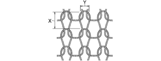
- FIG. 4 is an explanatory plan view of the mesh of the wire mesh shown in FIG.
- FIG. 5 is a perspective explanatory view of a belt-like sheet in the manufacturing process of the spherical belt-like sealing body of the present invention.
- FIG. 6 is a perspective explanatory view of a polymer in the production process of the ball-shaped seal body of the present invention.
- FIG. 7 is an explanatory plan view of a cylindrical base material in the manufacturing process of the ball-shaped seal body of the present invention.
- 8 is a cross-sectional explanatory view taken along line VIII-VIII of the cylindrical base material shown in FIG.
- FIG. 9 is a cross-sectional explanatory view of a method for forming a belt-like sheet in the manufacturing process of the spherical belt-like sealing body of the present invention.
- FIG. 10 is a perspective explanatory view of a belt-like sheet in the manufacturing process of the spherical belt-like sealing body of the present invention.
- FIG. 11 is a cross-sectional explanatory view of an example of a sheet for forming an outer layer in the manufacturing process of the ball-shaped seal body of the present invention.
- FIG. 12 is an explanatory diagram of a method for forming an outer surface layer forming sheet in the manufacturing process of the spherical belt-shaped sealing body of the present invention.
- FIG. 13 is a cross-sectional explanatory view of the outer layer forming sheet obtained by the forming method shown in FIG.
- FIG. 14 is a cross-sectional explanatory view of another forming method of the outer layer forming sheet in the manufacturing process of the spherical belt-shaped sealing body of the present invention.
- FIG. 12 is an explanatory diagram of a method for forming an outer surface layer forming sheet in the manufacturing process of the spherical belt-shaped sealing body of the present invention.
- FIG. 13 is a cross-sectional explanatory view of the outer layer forming sheet obtained by the forming method shown in FIG.
- FIG. 15 is a cross-sectional explanatory view of the outer layer forming sheet obtained by the forming method shown in FIG.
- FIG. 16 is an explanatory diagram of a ternary composition relating to the composition ratio of the solid lubricant in the present invention.
- FIG. 17 is a cross-sectional explanatory view of a sheet provided with a coating layer of a solid lubricant in the manufacturing process of the ball-shaped seal body of the present invention.
- FIG. 18 is a cross-sectional explanatory view of still another method of forming the outer layer forming sheet in the manufacturing process of the ball-shaped seal body of the present invention.
- FIG. 19 is an explanatory view of a forming method of still another example of the outer layer forming sheet in the manufacturing process of the ball-shaped seal body of the present invention.
- FIG. 20 is a cross-sectional explanatory view of an outer layer forming sheet obtained by another example forming method in the manufacturing process of the ball-shaped seal body of the present invention.
- FIG. 21 is a cross-sectional explanatory view of an outer layer type sheet provided with a coating layer of a solid lubricant in the manufacturing process of the ball-shaped seal body of the present invention.
- FIG. 22 is an explanatory plan view of a pre-cylindrical molded body in the manufacturing process of the ball-shaped seal body of the present invention.
- FIG. 23 is a cross-sectional explanatory view showing a state in which a preliminary cylindrical molded body is inserted into a mold in the manufacturing process of the ball-shaped seal body of the present invention.
- FIG. 24 is a partially enlarged cross-sectional explanatory view of FIG. 1 of another example of the preferred embodiment of the present invention.
- 25 is a partially enlarged cross-sectional explanatory view of FIG. 1 of still another example of the preferred embodiment of the present invention.
- FIG. 26 is a longitudinal cross-sectional explanatory view of an exhaust pipe spherical joint incorporating a preferred example of the ball-shaped seal body of the present invention.
- FIG. 27 is an explanatory diagram of an exhaust system of the engine.
- the acid-treated graphite powder is separated by suction filtration, and the washing operation of stirring the acid-treated graphite powder with water for 10 minutes and suction-filtering is repeated twice to sufficiently remove the sulfuric acid content from the acid-treated graphite powder.
- the acid-treated graphite powder from which the sulfuric acid content has been removed is dried for 3 hours in a drying furnace maintained at a temperature of 110 ° C. to obtain an acid-treated graphite powder.
- the acid-treated graphite powder is heated (expanded) at a temperature of 950 to 1200 ° C. for 1 to 10 seconds to generate decomposition gas, and expanded between the graphite layers by the gas pressure (expansion magnification 240). ⁇ 300 times).
- the expanded graphite particles are supplied to a twin-roller apparatus adjusted to a desired roll gap and roll-formed to produce a sheet I having a desired thickness.
- the heat-resistant material formed from the sheet I includes expanded graphite. Become.
- water in the structural formula is desorbed with aluminum dihydrogen phosphate.
- the aluminum dihydrogen phosphate and the expanded graphite particles are supplied to a twin-roller apparatus adjusted to a desired roll gap and roll-formed to produce a sheet II having a desired thickness.
- the heat-resistant material formed from the sheet II is expanded. It contains graphite and a phosphate composed of aluminum dihydrogen phosphate.
- dibasic lithium phosphate Li 2 HPO 4
- primary calcium phosphate Ca (H 2 PO 4 ) 2
- dicalcium phosphate CaHPO 4
- second Aluminum phosphate Al 2 (HPO 4 ) 3
- the acid-treated graphite powder was mixed with an aqueous solution of aluminum dihydrogen phosphate having a concentration of 50% as phosphate and orthophosphoric acid (H 3 having a concentration of 84% as phosphoric acid).
- a solution obtained by diluting a PO 4 ) aqueous solution with methanol is mixed in a spray form, and stirred uniformly to prepare a wettable mixture.
- the wettable mixture is dried for 2 hours in a drying oven maintained at a temperature of 120 ° C. Subsequently, this was heated (expanded) at a temperature of 950 to 1200 ° C.
- expanded graphite particles were expanded by expanding the graphite layer by the gas pressure (expansion magnification 240 to 300). Times).
- water in the structural formula is eliminated with aluminum dihydrogen phosphate, and dehydration reaction occurs with orthophosphoric acid to produce phosphorus pentoxide.
- the aluminum dihydrogen phosphate, phosphorus pentoxide, and expanded graphite particles are supplied to a twin-roller apparatus adjusted to a desired roll gap and roll-formed to produce a sheet III having a desired thickness, and the heat resistance formed from the sheet III.
- the material includes expanded graphite, a phosphate composed of aluminum dihydrogen phosphate, and phosphoric acid composed of phosphorus pentoxide.
- phosphoric acid in addition to orthophosphoric acid, metaphosphoric acid (HPO 3 ) or polyphosphoric acid can be used.
- Sheets I, II and III preferably have a density of 1.0 to 1.5 Mg / m 3 , more preferably about 1.0 to 1.2 Mg / m 3 when a heat-resistant material is produced therefrom. It has a density, and preferably has a thickness of about 0.3 to 0.6 mm.
- the reinforcing material of the spherical belt-shaped substrate and the outer layer examples include austenitic SUS304, SUS310S, SUS316, ferritic SUS430, etc. -Formed by weaving or knitting one or more fine metal wires consisting of nickel alloy (white copper) wire, copper-nickel-zinc alloy (white and white) wire, brass wire, and beryllium copper wire. A woven or braided wire mesh is used.
- a metal fine wire having a wire diameter in the range of 0.28 to 0.32 mm is preferably used, and a wire mesh formed with a metal fine wire having such a wire diameter is preferred.
- the lateral width Y is about 1.5 to 5 mm.
- the acid-treated graphite powder is preferably heated (expanded) at a temperature of 950 to 1200 ° C. for 1 to 10 seconds to generate a decomposition gas, and the graphite pressure is generated by the gas pressure.
- An expanded graphite powder that is expanded by expanding the layers to an expansion ratio of 240 to 300 times is used. This expanded graphite powder has a bulk density as low as 0.05 g / cm 3 and is difficult to handle.
- the expanded graphite powder is supplied to a twin roll apparatus adjusted to a desired roll gap and roll-formed to produce a sheet made of expanded graphite having a desired thickness, and the sheet is cut and pulverized. It is preferable to use expanded graphite powder obtained by pulverization with a machine as expanded graphite.
- a sheet made of expanded graphite it is possible to effectively use, for example, a so-called end material that is generated when a sheet I used for manufacturing a heat-resistant material for a spherical base is cut out along a desired mold. Therefore, the material cost of the expanded graphite can be reduced, and as a result, the cost of the ball-shaped seal body itself can be reduced.
- Outer layer heat-resistant material As the heat-resistant material for the outer layer, an expanded graphite powder, metal fibers, metal alloy fibers or ceramic fibers as inorganic fibers, and an inorganic shape-retaining material solution containing 30 to 50% as a solid content are prepared, and these are 1: 0.
- .5-3 0.05-3, preferably 1: 0.5-2: 0.1-0.15 in a mixing ratio (mass ratio) or expanded graphite powder and metal fiber,
- a metal alloy fiber or ceramic fiber, a metal powder, a metal alloy powder or ceramic powder, and an inorganic shape-retaining material solution are prepared, and these are 1: 0.5 to 3: 0.5 to 3: 0.5 to 0 .3, preferably in a mixing ratio (mass ratio) of 1: 0.5 to 2: 0.5 to 2: 0.1 to 0.15, and these are put into a powder granulator and kneaded. The mixture is then granulated to produce a wettable mixture and used in the form of this mixture.
- Solid lubricant comprising a PTFE powder having an average particle size of 0.01 to 1 ⁇ m, an FEP powder having an average particle size of 0.01 to 1 ⁇ m, and an h-BN powder having an average particle size of 0.1 to 20 ⁇ m
- a PTFE powder having an average particle size of 0.01 to 1 ⁇ m
- an FEP powder having an average particle size of 0.01 to 1 ⁇ m
- an h-BN powder having an average particle size of 0.1 to 20 ⁇ m
- it is manufactured from an aqueous dispersion in which 4% by mass of a surfactant and 57% by mass of water are mixed with respect to 39% by mass of the powder.
- the surfactant contained in the aqueous dispersion may be any surfactant that can uniformly disperse the lubricating composition powder in water.
- anionic surface activity such as sodium alkyl sulfate, sodium alkyl ether sulfate, triethanolamine alkyl sulfate, triethanolamine alkyl ether sulfate, ammonium alkyl sulfate, ammonium alkyl ether sulfate, sodium alkyl ether phosphate and sodium fluoroalkylcarboxylate Agent
- cationic surfactant such as alkyl ammonium salt and alkyl benzyl ammonium salt, polyoxyethylene alkyl ether, polyoxyethylene phenyl ether, polyoxyethylene alkyl ester, propylene glycol-propylene oxide copolymer, perfluoroalkyl ethylene oxide addition And 2-ethylhexanol ethylene oxide
- Nonionic surfactants and the alkyl betaine de adduct amphoteric surfactants such as alkyl amido betaine, and imidazolium betaine.
- aqueous dispersion In an aqueous dispersion, if the surfactant content is too low, the dispersion of the lubricating composition powder will not be uniform, and if the surfactant content is too high, the decomposition residue of the surfactant due to baking will be lost. In addition to increasing coloration, the heat resistance and non-adhesiveness of the coating layer are reduced.
- the aqueous dispersion containing the lubricating composition powder, the surfactant and water is further replaced with a part of the content of h-BN powder in the lubricating composition powder, and 20 wt% or less of the alumina hydrate powder. You may contain.
- aqueous dispersions may further contain a water-soluble organic solvent.
- the water-soluble organic solvent include alcohol solvents such as methanol, ethanol, butanol, isopropyl alcohol and glycerin, ketone solvents such as acetone, methyl ethyl ketone and methyl isobutyl ketone, ether solvents such as methyl cellosolve, cellosolve and butyl cellosolve, Examples thereof include glycol solvents such as ethylene glycol, propylene glycol, triethylene glycol and tetraethylene glycol, amide solvents such as dimethylformamide and dimethylacetamide, and lactam solvents such as N-methyl-2-pyrrolidone.
- the content of the water-soluble organic solvent is 0.5 to 50% by mass, preferably 1 to 30% by mass, based on the total amount of water.
- the water-soluble organic solvent has a function of wetting the PTFE powder and the FEP powder, forms a uniform mixture with the h-BN powder, and evaporates when dried, so that the coating layer is not adversely affected.
- the aqueous dispersion is applied to one surface of a sheet to be an outer layer heat-resistant material or outer layer forming member by means of roller coating, brush coating, spraying, etc., and after drying this aqueous dispersion, it is applied to one surface of the sheet.
- a coating layer of solid lubricant is formed. After drying, the coating layer is heated to (T) to (T + 150 ° C.), preferably (T + 5 ° C.) to (T + 135 ° C.), more preferably (T + 10 ° C.) to a melting point T of 245 ° C. It may be fired for 10 to 30 minutes at a temperature within the range of (T + 125 ° C.), and by firing the solid lubricant coating layer, a fired coating layer of the solid lubricant is formed on one surface of the sheet .
- a cylindrical braided wire mesh 1 is passed between rollers 2 and 3 to produce a strip metal mesh 4 having a predetermined width D, and the belt metal mesh 4 is cut into a predetermined length L.
- a belt-shaped wire net 5 for a spherical belt-shaped substrate having a mesh width of a longitudinal width X and a width Y is prepared as a reinforcing material for the substrate.
- the width d of the metal mesh 5 is (1.10 ⁇ D) mm to (2.10 ⁇ D) mm and the length L of the metal mesh 5 is (1.
- a belt-like sheet 6 made of a sheet I, II, or III, which is a heat-resistant material for a spherical belt-shaped substrate, is prepared so as to have a length l of 30 ⁇ L) mm to (2.70 ⁇ L) mm.
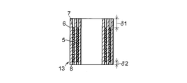
- the width direction of the metal mesh 5 which is (0.10 to 0.80) ⁇ Dmm at the maximum from the one end edge 7 in the width direction of the metal mesh 5 and becomes the annular end surface 46 side on the small diameter side of the partially convex spherical surface 44
- the sheet 6 is protruded in the width direction with an amount of protrusion ⁇ 1 larger than the amount of protrusion ⁇ 2 from the other end edge 8 of the sheet, and the sheet 6 is maximum (0.30 to 1.70) ⁇ Lmm protrudes in the length direction, and the other edge 10 in the length direction of the wire mesh 5 and the edge 11 in the length direction of the sheet 6 corresponding to the edge 10 are matched with the sheet 6
- a polymer 12 obtained by superimposing the metal mesh 5 on each other is obtained.
- the polymer 12 is spirally wound with the sheet 6 inside, and the sheet 6 is wound once so that the number of the sheets 6 is increased once, and the sheet 6 is formed on both the inner peripheral side and the outer peripheral side.
- a cylindrical base material 13 is formed in which is exposed.
- the length of the wire mesh 5 is increased from (1.30 ⁇ L) mm to (2.70) so that the number of windings in the cylindrical base material 13 is one more than the number of windings of the wire mesh 5.
- XL Prepare a material having a length l of mm in advance. In the cylindrical base material 13, the sheet 6 protrudes in the width direction by ⁇ 1 and ⁇ 2 from one and the other end edges 7 of the wire net 5 on one and other end edges in the width direction.
- the blending ratio (mass ratio) is 1: 0.5 to 3: 0.5 to 0.3, preferably the blending ratio (mass ratio) is 1: 0.5 to 2: 0.1 to 0.15.
- the inorganic shape-retaining material solution containing mass% is put into a powder granulator and kneaded and
- a mixture 14 is supplied from conveyors 17 and 18 into a hopper 16 of a rolling mill 15 having a load cell 22 arranged on the roller 19 side and a fluid cylinder 23 arranged on the roller 20 side. Then, the mixture 14 is sequentially supplied from the hopper 16 to the gap between the pair of rollers 19 and 20, the mixture 14 is rolled between the rollers 19 and 20, and the rolled mixture 14 is dried to dissipate and remove moisture.
- a belt-like sheet 21 having a width d1 smaller than the width d of the sheet 6 and having a length l1 is produced, while a cylindrical braided wire mesh 1 for the outer layer is passed between the rollers 2 and 3 and the sheet 21
- Has eye width A belt-like wire mesh 5a for the outer layer to be prepared is prepared, and as shown in FIG. 11, the sheet 21 is inserted into the wire mesh 5a and these are integrated by passing between rollers 24 and 25 as shown in FIGS. Then, as shown in FIG. 13, the outer layer forming member I composed of the outer layer forming member 30a in which the surface 28 composed of the wire mesh 5a and the surface 29 composed of the sheet 21 are mixed on one and the other surfaces 26 and 27 is produced.
- outer layer forming member II ⁇ Formation of outer layer forming member II> As shown in FIG. 14, the wire mesh 5a is inserted into the hopper 16 in the rolling device 15, the insertion end of the wire mesh 5a is passed between the pair of rollers 19 and 20, and the conveyor is placed in the hopper 16 divided by the wire mesh 5a.
- the mixture 14 supplied from 17 and 18 is supplied to the belt-like wire mesh 5a between the pair of rollers 19 and 20, and the supplied mixture 14 is rolled between the rollers 19 and 20 together with the wire mesh 5a to form the mesh of the wire mesh 5a.
- the mixture 14 is filled, and the wire mesh 5a and the mixture 14 held in the mesh of the wire mesh 5a are integrated.
- the surface 28 made of the wire mesh 5a and the surface 29 made of the sheet 21 are mixed.
- outer layer forming member II which consists of outer layer forming member 30b with the other surfaces 26 and 27 is produced.
- PTFE powder having an average particle diameter of 0.01 to 1 ⁇ m
- FEP powder having an average particle diameter of 0.01 to 1 ⁇ m
- h-BN powder having an average particle diameter of 0.1 to 20 ⁇ m
- composition ratio in the numerical range corresponding to the region P bounded by the quadrangle 57 or the region Q bounded by the hexagon 58 in the left oblique side of the page indicates the content (mass%) of h-BN.
- An aqueous dispersion comprising 39% by weight of a lubricating composition powder, 4% by weight of a surfactant and 57% by weight of water; (2)
- the content of h-BN powder is ensured to be 45% by mass or more, and alumina hydrate is substituted for a part of the h-BN powder content.
- An aqueous dispersion comprising 39% by mass of the lubricating composition powder of (1) containing 20% by mass or less of powder, 4% by mass of a surfactant and 57% by mass of water; (3) The aqueous dispersion of (1) above further contains a water-soluble organic solvent in an amount of 0.1 to 22.5% by mass, and (4) The aqueous dispersion of (2) is further water-soluble.
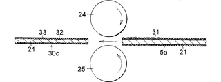
- a coating layer 31 of a solid lubricant is formed on the surface, and a wire mesh 5a prepared by the same method as described above is inserted into the wire mesh 5a with the sheet 21 provided with the coating layer 31 as shown in FIG. As shown in FIG. 19, these are integrated by passing between rollers 24 and 25, and the sheet 21 and the coating layer 31 are filled in the mesh of the wire mesh 5 a, and the surface of the wire mesh 5 a is formed as shown in FIG. 20.
- the outer layer forming member III including the flat outer layer forming member 30c having one surface in which the surface 32 and the surface 33 including the coating layer are mixed is prepared.
- ⁇ Formation of outer layer forming member IV> Apply one of the aqueous dispersions (1) to (4) to one surface of the outer layer forming member 30a or 30b by means of brushing, roller coating, spraying, or the like, and let it dry. Then, the coating layer 31 of the solid lubricant is formed, and as shown in FIG. 21, an outer layer forming member IV including the outer layer forming member 30d having only one surface 33 made of the coating layer 31 is produced.
- the outer layer forming member 30a, 30b, 30c, or 30d has one surface where the surface 28 made of the wire mesh 5a and the surface 29 made of the sheet 21 are mixed, the surface 32 made of the wire mesh 5a, and the coating layer 31.
- One surface where only the surface 33 made of the solid lubricant is mixed or one surface consisting only of the surface 33 of the coating layer 31 is wound outwardly and wound around the outer peripheral surface of the cylindrical base material 13 once to form a preliminary cylindrical molded body 34. Is made.
- the inner surface includes a cylindrical wall surface 35, a partially convex spherical wall surface 36 continuous to the cylindrical wall surface 35, and a through hole 37 continuous to the partially convex spherical wall surface 36.
- a hollow core 38 is hollowed by inserting a stepped core 38 into the through hole 37.
- a mold 41 as shown in FIG. 23 in which a cylindrical portion 39 and a spherical hollow portion 40 connected to the hollow cylindrical portion 39 are formed is prepared, and the preliminary cylindrical molded body 34 is inserted into the stepped core 38 of the mold 41. .
- the pre-cylindrical molded body 34 disposed in the hollow cylindrical portion 39 and the spherical belt-shaped hollow portion 40 of the mold 41 is compression-molded at a pressure of 98 to 294 N / mm 2 (1 to 3 ton / cm 2 ) in the core axial direction.
- a spherical band base 47 having a cylindrical inner surface 43, which is defined by annular end surfaces 45 and 46, and an outer layer 49 integrally formed on the outer surface 48 of the spherical band base 47.
- the provided ball-shaped seal body 50 is produced.
- the spherical belt-shaped base body 47 is filled with the reinforcing material made of the compressed wire mesh 5 and the mesh of the wire mesh 5 of the reinforcing material, and is mixed and integrated with this reinforcing material.
- the sheet I is used as the sheet 6
- the heat-resistant material including expanded graphite made of the compressed sheet 6 is used.
- the sheet II is used as the sheet 6
- the compressed sheet 6 is used.
- the sheet 6 is used as the sheet 6, the expanded graphite composed of the expanded graphite and the aluminum dihydrogen phosphate.
- the outer layer forming member 30 a or 30 b (outer layer forming member I or II) is used, the outer layer 49 is compressed.
- a heat-resistant material containing an inorganic shape-retaining material or expanded graphite, inorganic fiber, inorganic shape-retaining material and inorganic powder, and the outer surface 51 constituting the partially convex spherical surface 44 of the outer layer 49 has a reinforcing material And a surface 52 of heat-resistant material containing expanded graphite, inorganic fiber and inorganic shape-retaining material or expanded graphite, inorganic fiber, inorganic shape-retaining material, and inorganic powder.
- the outer layer 49 includes a reinforcing member made of a compressed wire mesh 5a and a wire mesh 5a of the reinforcing material. And fill the mesh Heat-resisting material or expanded graphite, inorganic fiber, inorganic shape-retaining material, and inorganic powder comprising expanded graphite, inorganic fiber, and inorganic shape-retaining material that are mixed and integrated with reinforcing wire mesh 5a And a solid lubricant containing PTFE, FEP, and h-BN, which is formed of a coating layer 31 that is mixed and integrated with the wire mesh 5a and the heat-resistant material.
- a surface 52 made of a reinforcing metal mesh 5 a and a surface 53 of a solid lubricant made of a compressed coating layer 31 are mixed to form an outer layer.
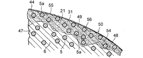
- the outer layer 49 is filled with the reinforcing material made of the compressed wire mesh 5a and the wire mesh 5a of the reinforcing material, as shown in FIG. Mixed with metal wire mesh 5a
- An intermediate layer 54 that is provided with a heat-resistant material composed of the integrated and compressed sheet 21 and that is integrally formed on the outer surface 48 of the spherical belt-like substrate 47, and covers the intermediate layer 54.
- the outer surface 51 constituting the partially convex spherical surface 44 of the outer layer 49 is formed of the coating layer 31 and includes the coating layer 55 containing the solid lubricant made of the coating layer 31.
- the surface 56 consists of a solid lubricant.
- a flange 200 is erected on the outer peripheral surface of the upstream exhaust pipe 100 connected to the engine side, leaving the pipe end 101, and the pipe end 101 has A spherical belt-like seal body 50 is fitted on a cylindrical inner surface 43 that defines the through hole 42, and the spherical belt-like seal body 50 is seated against the flange 200 at the annular end surface 45 on the large diameter side, and is upstream.
- the downstream exhaust pipe 300 disposed opposite to the side exhaust pipe 100 and connected to the muffler side is integrally provided with a concave spherical portion 302 and a flange portion 303 connected to the concave spherical portion 302.
- the enlarged portion 301 is fixed, and the spherical seal body 50 is slidably contacted with the outer surface 51 of the outer layer 49 constituting the partially convex spherical surface 44 to the concave spherical inner surface 304 of the concave spherical portion 302.
- One end is A pair of bolts 400 fixed to the flange 200 and having the other end inserted through the flange 303 and a pair of coil springs 500 disposed between the enormous head of the bolt 400 and the flange 303.
- the exhaust pipe 300 is always biased with a spring force toward the upstream side exhaust pipe 100, and the exhaust pipe spherical joint has a relative angular displacement of the downstream side exhaust pipe 300 with respect to the upstream side exhaust pipe 100. This is allowed by sliding contact between the outer surface 51 as the sliding surface of the outer layer 49 of the spherical belt-shaped sealing body 50 and the inner surface 304 of the concave spherical surface portion 302.
- the exhaust gas generated in each cylinder of the automobile engine is collected in the exhaust manifold catalytic converter 600, sent to the sub-muffler 603 through the exhaust pipe 601 and the exhaust pipe 602, and passes through the sub-muffler 603.
- the exhaust gas is further sent to a muffler (silencer) 606 through an exhaust pipe 604 and an exhaust pipe 605, and is discharged into the atmosphere through the muffler 606.
- Exhaust system members such as 603 and muffler 606 are repeatedly subjected to stress due to the roll behavior and vibration of the engine, and particularly in the case of a high-power engine at high speed rotation, the stress applied to the exhaust system members is considerably large. Exhaust system members may be fatigued and engine vibrations may cause exhaust system members 26, the connection portion 607 between the exhaust manifold catalytic converter 600 and the exhaust pipe 601 and the connection portion 608 between the exhaust pipe 604 and the exhaust pipe 605 are formed by the exhaust pipe spherical joint shown in FIG.
- the movable connection absorbs the stress repeatedly applied to the exhaust system member due to the roll behavior and vibration of the automobile engine, prevents fatigue failure of the exhaust system member and the vibration of the engine causes the exhaust system member to resonate. The problem of worsening the quietness of the room is also solved.
- SUS304 austenitic stainless steel wire
- FIG. 1 and FIG. 2 that are compression molded at a pressure of 294 N / mm 2 (3 ton / cm 2 ) using a die 41 from a pre-cylindrical molded body 34 produced by winding once on the outer peripheral surface of the shaped base material 13.
- the heat-resistant material of the outer layer 49 of the produced spherical belt-shaped sealing body 50 is 71.1% by volume and 19.9% by volume of expanded graphite, iron fiber, and magnesium dihydrogen phosphate, respectively. % And 9.0% by volume It was.
- Example 2 The expanded graphite powder, iron fiber, and magnesium dihydrogen phosphate solution as in Example 1 were expanded at a mass ratio of 1: 1.5: 0.5 (solid content 0.15, moisture 0.35).
- a wettable mixture 14 consisting of 33.3% by mass of graphite powder, 50% by mass of iron fiber, 5% by mass of magnesium dihydrogen phosphate and 11.7% by mass of water was prepared.
- 1 and FIG. 2 is manufactured, and the heat-resistant material of the outer layer 49 of the manufactured spherical band-shaped seal body 50 is 64.5 volumes of expanded graphite, iron fiber, and magnesium dihydrogen phosphate. %, 27.4% by volume and 8.1% by volume.
- Example 3 An expanded graphite powder similar to that in Example 1, copper fibers having an average fiber diameter of 60 ⁇ m and an average fiber length of 3 mm as inorganic fibers, and a magnesium dihydrogen phosphate solution similar to Example 1 in a mass ratio of 1: 1: 0. .5 (solid content 0.15, moisture 0.35), and has wettability composed of expanded graphite powder 40% by mass, copper fiber 40% by mass, magnesium dihydrogen phosphate 6% by mass and moisture 14% by mass.
- a mixture 14 was prepared, and the spherical band-shaped sealing body 50 shown in FIGS. 1 and 2 was manufactured in the same manner as in Example 1 below.
- the heat-resistant material of the outer layer 49 of the manufactured spherical band-shaped sealing body 50 was expanded. It contained 72.8% by volume, 18.0% by volume and 9.2% by volume of graphite, copper fiber and magnesium dihydrogen phosphate, respectively.
- Example 4 The expanded graphite powder, the copper fiber, and the magnesium dihydrogen phosphate solution as in Example 3 were expanded at a mass ratio of 1: 1.8: 0.5 (solid content 0.15, moisture 0.35).
- a wettable mixture 14 consisting of 30.3% by mass of graphite powder, 54.5% by mass of copper fibers, 4.6% by mass of magnesium dihydrogen phosphate and 10.6% by mass of water was prepared.
- 1 and FIG. 2 is manufactured by the same method, and expanded graphite, copper fiber, and magnesium dihydrogen phosphate are respectively used as the heat-resistant material for the outer layer 49 of the manufactured ball-shaped seal body 50. 63.6% by volume, 28.1% by volume and 8.3% by volume were contained.
- Example 5 Expanded graphite powder similar to that in Example 3, with a mixing ratio of 1: 3: 0.5 (solid content 0.15, moisture 0.35) of copper fiber and magnesium dihydrogen phosphate solution in mass ratio A mixture 14 having wettability composed of 22.2% by mass, copper fiber 66.7% by mass, magnesium dihydrogen phosphate 3.3% by mass and water 7.8% by mass was prepared. 1 and FIG. 2 is manufactured by the method, and the heat-resistant material of the outer layer 49 of the manufactured spherical strip-shaped seal body 50 includes expanded graphite, copper fiber, and magnesium dihydrogen phosphate, respectively. 4 vol%, 39.7 vol% and 6.9 vol% were contained.
- Example 6 An expanded graphite powder similar to that of Example 1, an aluminum fiber having an average fiber diameter of 90 ⁇ m and an average fiber length of 3 mm as inorganic fibers, and a magnesium dihydrogen phosphate solution similar to that of Example 1 were used at a mass ratio of 1: 0. 5: 0.5 (solid content 0.15, moisture 0.35), expanded graphite powder 50% by mass, aluminum fiber 25% by mass, aluminum dihydrogen phosphate 7.5% by mass, and moisture 17.5% by mass %, And a spherical belt-like seal body 50 shown in FIGS. 1 and 2 is produced in the same manner as in Example 1 and the outer layer 49 of the produced spherical belt-like seal body 50 is prepared.
- the heat-resistant material contained 65.1% by volume, 26.5% by volume, and 8.4% by volume of expanded graphite, aluminum fiber, and magnesium dihydrogen phosphate, respectively.
- Example 7 An expanded graphite powder similar to that in Example 6, a titanium fiber having an average fiber diameter of 30 ⁇ m and an average fiber length of 1 mm as inorganic fibers, and a magnesium dihydrogen phosphate solution similar to that in Example 1 in a mass ratio of 1: 1: 0. .5 (solid content 0.15, moisture 0.35), and has wettability composed of expanded graphite powder 40% by mass, titanium fiber 40% by mass, magnesium dihydrogen phosphate 6% by mass and moisture 14% by mass.
- a mixture 14 was prepared, and the spherical band-shaped sealing body 50 shown in FIGS. 1 and 2 was manufactured in the same manner as in Example 1 below.
- the heat-resistant material of the outer layer 49 of the manufactured spherical band-shaped sealing body 50 was expanded.
- the graphite, titanium fiber, and magnesium dihydrogen phosphate contained 61.9% by volume, 30.3% by volume, and 7.8% by volume, respectively.
- Example 8 Expanded graphite powder and iron fiber similar to Example 1, copper fiber similar to Example 3, and magnesium dihydrogen phosphate solution similar to Example 6 in a mass ratio of 1: 1: 1: 0.5 (Expansion graphite powder 28.6% by mass, iron fiber 28.6% by mass, copper fiber 28.6% by mass, magnesium dihydrogen phosphate 4.2% by mass (solid content 0.15, moisture 0.35) %, And a mixture 14 having a wettability composed of 10% by mass of water, and a spherical belt-like seal body 50 shown in FIGS. 1 and 2 was produced in the same manner as in Example 1 below. As the heat-resistant material of the outer layer 49 of the body 50, expanded graphite, iron fiber, copper fiber, and magnesium dihydrogen phosphate are 60.7% by volume, 16.8% by volume, 15.0% by volume, and 7.5% by volume, respectively. Contained.
- Example 9 Mass ratio of expanded graphite powder similar to Example 1, SUS434 (ferritic stainless steel) fiber having an average fiber diameter of 50 ⁇ m and an average fiber length of 2 mm as inorganic fiber, and magnesium dihydrogen phosphate solution similar to Example 1 1: 0.5: 0.5 (solid content 0.15, moisture 0.35) in a mixing ratio of 50% by mass of expanded graphite powder, 25% by mass of SUS434 fiber, 7.5% by mass of magnesium dihydrogen phosphate, and A wet mixture 14 having a moisture content of 17.5% by mass was prepared, and a spherical belt-shaped sealing body 50 shown in FIG. 1 and FIG.
- the heat-resistant material of the outer layer 49 of the body 50 contained 78.8% by volume, 11.1% by volume, and 10.1% by volume of expanded graphite, SUS434 fiber, and magnesium dihydrogen phosphate, respectively.
- Example 10 The expanded graphite powder, the SUS434 fiber, and the magnesium dihydrogen phosphate solution as in Example 9 were expanded at a mass ratio of 1: 0.8: 0.5 (solid content 0.15, moisture 0.35).
- a wettable mixture 14 consisting of 43.5% by mass of graphite powder, 34.8% by mass of SUS434 fiber, 6.5% by mass of magnesium dihydrogen phosphate and 15.2% by mass of water was prepared.
- 1 and FIG. 2 is manufactured by the same method, and expanded graphite, SUS434 fiber, and magnesium dihydrogen phosphate are respectively used as the heat-resistant material of the outer layer 49 of the manufactured ball strip-shaped seal body 50. 73.9 vol%, 16.8 vol% and 9.3 vol% were contained.
- Example 11 Expanded graphite powder in the same proportion as in Example 9: expanded graphite powder, SUS434 fiber, and magnesium dihydrogen phosphate solution at a mass ratio of 1: 1: 0.5 (solid content 0.15, moisture 0.35).
- FIGS. And the heat-resistant material of the outer layer 49 of the produced spherical belt-shaped sealing body 50 is expanded graphite, SUS434 fiber, and magnesium dihydrogen phosphate, 70.8% by volume and 20.2% by volume, respectively. % And 9.0% by volume.
- Example 12 The expanded graphite powder, the SUS434 fiber, and the magnesium dihydrogen phosphate solution as in Example 9 were expanded at a mass ratio of 1: 1.5: 0.5 (solid content 0.15, moisture 0.35).
- a wettable mixture 14 consisting of 33.3% by weight of graphite powder, 50% by weight of SUS434 fiber, 5% by weight of magnesium dihydrogen phosphate and 11.7% by weight of water was prepared.
- 1 and FIG. 2 is manufactured, and the heat-resistant material of the outer layer 49 of the manufactured spherical belt-shaped seal body 50 includes expanded graphite, SUS434 fiber, and magnesium dihydrogen phosphate in 64.2 volumes. %, 27.7% by volume and 8.1% by volume.
- Example 13 Expanded graphite powder as in Example 9, with a mixing ratio of 1: 2: 0.5 (solid content 0.15, moisture 0.35) of SUS434 fiber and magnesium dihydrogen phosphate solution in a mass ratio.
- 1 and FIG. 2 are manufactured, and the heat resistant material of the outer layer 49 of the manufactured spherical band seal 50 includes 58.8 volumes of expanded graphite, SUS434 fiber, and magnesium dihydrogen phosphate, respectively. %, 33.5% by volume, and 7.7% by volume.
- Example 14 Expanded graphite powder as in Example 9, with a mixing ratio of 1: 3: 0.5 (solid content 0.15, moisture 0.35) of SUS434 fiber and magnesium dihydrogen phosphate solution in a mass ratio.
- 1 and FIG. 2 is manufactured by the method, and the heat-resistant material of the outer layer 49 of the manufactured ball-shaped seal body 50 is expanded graphite, SUS434 fiber, and magnesium dihydrogen phosphate, respectively. 2 vol%, 43.3 vol% and 6.5 vol% were contained.
- Example 15 Expanded graphite powder similar to Example 1, carbon fiber (steel: S15C) fiber having an average fiber diameter of 55 ⁇ m and an average fiber length of 2 mm as inorganic fibers, and aluminum dihydrogen phosphate having a solid content of 50% as inorganic shape-retaining materials
- the solution was mixed at a mass ratio of 1: 1: 0.5 (solid content 0.1, moisture 0.4), expanded graphite powder 40% by mass, carbon steel fiber 40% by mass, aluminum dihydrogen phosphate 4
- a mixture 14 having a wettability composed of mass% and moisture 16 mass% was prepared, and a spherical belt-shaped sealing body 50 shown in FIGS. 1 and 2 was manufactured in the same manner as in Example 1 below.
- the heat-resistant material of the outer layer 49 of the sealing body 50 contained 70.8% by volume, 18.7% by volume, and 10.5% by volume of expanded graphite, carbon steel fiber, and aluminum dihydrogen phosphate, respectively.
- Example 16 The same ratio of expanded graphite powder, carbon steel fiber, and aluminum dihydrogen phosphate solution as in Example 15 in a mass ratio of 1: 1.5: 0.5 (solid content 0.1, moisture 0.4) A wettable mixture 14 consisting of 33.3% by mass of expanded graphite powder, 50% by mass of carbon steel fibers, 3.3% by mass of aluminum dihydrogen phosphate and 13.4% by mass of water was prepared. 1 and FIG. 2 is manufactured by the same method, and the heat-resistant material of the outer layer 49 of the manufactured ball-shaped seal body 50 includes expanded graphite, carbon steel fiber, and aluminum dihydrogen phosphate. 63.7% by volume, 27% by volume and 9.3% by volume were contained, respectively.
- Example 17 Expanded graphite powder similar to Example 1, copper-zinc alloy (brass: Cu60, Zn40) fibers having an average fiber diameter of 60 ⁇ m and an average fiber length of 3 mm as inorganic fibers, and an aluminum dihydrogen phosphate solution similar to Example 15
- a mass ratio of 1: 1: 0.5 (solid content 0.1, moisture 0.4) expanded graphite powder 40% by mass, copper-zinc alloy fiber 40% by mass, aluminum dihydrogen phosphate
- a mixture 14 having a wettability composed of 4% by mass and 16% by mass of water was prepared, and a spherical belt-shaped sealing body 50 shown in FIGS. 1 and 2 was prepared in the same manner as in Example 1 below.
- the heat-resistant material of the outer layer 49 of the belt-shaped sealing body 50 contained 70.8% by volume, 18.7% by volume, and 10.5% by volume of expanded graphite, copper-zinc alloy fiber, and aluminum dihydrogen phosphate, respectively. .
- Example 18 The same expanded graphite powder as in Example 17, copper-zinc alloy fiber and aluminum dihydrogen phosphate solution in a mass ratio of 1: 1.8: 0.5 (solid content 0.1, moisture 0.4).
- Producing a wettable mixture 14 consisting of 30.3% by weight expanded graphite powder, 54.5% by weight copper-zinc alloy fiber, 3% by weight aluminum dihydrogen phosphate and 12.2% by weight moisture, 1 and FIG. 2 was manufactured in the same manner as in Example 1, and expanded graphite and copper-zinc alloy fiber were used as the heat-resistant material for the outer layer 49 of the manufactured spherical strip seal body 50.
- aluminum dihydrogen phosphate contained 61.1% by volume, 30.1% by volume and 8.8% by volume, respectively.
- Example 19 An expanded graphite powder similar to that in Example 1, copper-tin alloy (phosphor bronze) fibers having an average fiber diameter of 60 ⁇ m and an average fiber length of 2 mm as inorganic fibers, and an aluminum dihydrogen phosphate solution similar to that in Example 15, In a mass ratio of 1: 1.5: 0.5 (solid content 0.1, moisture 0.4), expanded graphite powder 33.3% by mass, copper-tin alloy fiber 50% by mass, dihydrogen phosphate A mixture 14 having wettability composed of 3.3% by mass of aluminum and 13.4% by mass of water was prepared, and the spherical band-shaped sealing body 50 shown in FIGS. 1 and 2 was manufactured in the same manner as in Example 1 below.
- copper-tin alloy phosphor bronze
- the heat-resistant material of the outer layer 49 of the produced spherical belt-shaped sealing body 50 includes 65.9% by volume, 24.5% by volume, and 9.6% by volume expanded graphite, copper-tin alloy fiber, and aluminum dihydrogen phosphate, respectively. % Contained.
- Example 20 The same expanded graphite powder and SUS434 fiber as in Example 9 and the same iron fiber and magnesium dihydrogen phosphate solution as in Example 1 were used at a mass ratio of 1: 1: 0.5: 0.5 (solids content: 0. 15, moisture 0.35), expanded graphite powder 33.3% by mass, SUS434 fiber 33.3% by mass, iron fiber 16.7% by mass, magnesium dihydrogen phosphate 5% by mass and moisture 11.7% by mass %, And a spherical belt-like seal body 50 shown in FIGS. 1 and 2 is produced in the same manner as in Example 1 and the outer layer 49 of the produced spherical belt-like seal body 50 is prepared.
- the heat-resistant material contained 64.5% by volume, 18.4% by volume, 9.0% by volume, and 8.1% by volume of expanded graphite, SUS434 fiber, iron fiber, and magnesium dihydrogen phosphate, respectively.
- Example 21 Expanded graphite powder and SUS434 fiber similar to Example 20, and copper fiber and magnesium dihydrogen phosphate solution similar to Example 3 were mixed at a mass ratio of 1: 1: 1: 0.5 (solid content 0.15, With a blending ratio of moisture 0.35), expanded graphite powder 28.6% by mass, SUS434 fiber 28.6% by mass, copper fiber 28.6% by mass, magnesium dihydrogen phosphate 4.2% by mass and moisture 10% by mass
- the wettable mixture 14 is manufactured, and the ball-shaped seal body 50 shown in FIGS. 1 and 2 is manufactured in the same manner as in Example 1 below.
- the heat resistance of the outer layer 49 of the manufactured ball-band-shaped seal body 50 is as follows. The material contained 60.5% by volume, 17.2% by volume, 14.9% by volume and 7.4% by volume of expanded graphite, SUS434 fiber, copper fiber and magnesium dihydrogen phosphate, respectively.
- Example 22 Expanded graphite powder and SUS434 fiber similar to Example 9, copper-zinc alloy fiber similar to Example 17, and magnesium dihydrogen phosphate solution similar to Example 1 in a mass ratio of 1: 1: 0. 5: 0.5 (solid content 0.15, moisture 0.35) in a mixing ratio, expanded graphite powder 33.3% by mass, SUS434 fiber 33.3% by mass, copper-zinc alloy fiber 16.7% by mass, A mixture 14 having wettability composed of 5% by mass of magnesium dihydrogen phosphate and 11.7% by mass of water was prepared, and the spherical band-shaped sealing body 50 shown in FIGS. 1 and 2 was prepared in the same manner as in Example 1 below.
- the heat-resistant material of the outer layer 49 of the produced spherical belt-shaped sealing body 50 was expanded graphite, SUS434 fiber, copper-zinc alloy fiber, and magnesium dihydrogen phosphate, respectively, 64.8% by volume, 18.5% by volume, Contains 8.6% by volume and 8.1% by volume It had been.
- Example 23 An expanded graphite powder similar to that in Example 1, silica fibers having an average fiber diameter of 4 ⁇ m and an average fiber length of 1 mm as inorganic fibers, and an aluminum dihydrogen phosphate solution similar to that in Example 15 in a mass ratio of 1: 0. 5: 0.5 (solid content 0.1, moisture 0.4), a wet composition comprising expanded graphite powder 50% by mass, silica fiber 25% by mass, aluminum dihydrogen phosphate 5% by mass and moisture 20% by mass. 1 is prepared in the same manner as in Example 1, and a heat resistant material for the outer layer 49 of the produced ball-shaped seal body 50 is prepared. Contained 60.4% by volume, 30.3% by volume and 9.3% by volume of expanded graphite, silica fiber and aluminum dihydrogen phosphate, respectively.
- Example 24 The same expanded graphite powder as in Example 1, alumina-silica fibers (85% Al 2 O 3 -15% SiO 2 ) having an average fiber diameter of 15 ⁇ m and an average fiber length of 1 mm as inorganic fibers, and the same as in Example 1.
- the sealing body 50 was manufactured, and the heat-resistant material of the outer layer 49 of the manufactured spherical belt-shaped sealing body 50 was expanded graphite, alumina-silica fiber, and magnesium dihydrogen phosphate 68.0% by volume, 23.3% by volume, and Contains 8.7% by volume It had.
- Example 25 Expanded graphite powder, iron fiber and magnesium dihydrogen phosphate solution similar to those in Example 1 and molybdenum disulfide (MoS 2 ) powder added thereto were added in a mass ratio of 1: 1.5: 0.5 (solid content 0) .15, water content 0.35): 0.01%, expanded graphite powder 33.2% by mass, iron fiber 49.8% by mass, magnesium dihydrogen phosphate 5% by mass, molybdenum disulfide powder 0.3% by mass % And moisture 11.7% by mass, and a ball-shaped sealing body 50 shown in FIG. 1 and FIG.
- MoS 2 molybdenum disulfide
- expanded graphite, iron fiber, molybdenum disulfide, and magnesium dihydrogen phosphate are 64.6% by volume, 27.0% by volume, 0.3% by volume, and 8.%, respectively. 1% by volume was contained.
- Example 26 The same expanded graphite powder as in Example 9, SUS434 fiber and magnesium dihydrogen phosphate solution, and molybdenum disulfide (MoS 2 ) powder added thereto were used in a mass ratio of 1: 1.5: 0.5 (solid content 0). .15, moisture 0.35): 0.05, expanded graphite powder 32.8% by mass, SUS434 fiber 49.2% by mass, magnesium dihydrogen phosphate 4.9% by mass, molybdenum disulfide powder 1.
- a mixture 14 having a wettability composed of 6% by mass and 11.5% by mass of water is prepared, and a spherical belt-like sealing body 50 shown in FIGS. 1 and 2 is manufactured by the same method as in Example 1 and manufactured.
- Example 27 Expanded graphite powder, iron fiber and magnesium dihydrogen phosphate solution similar to those in Example 1 and iron powder having an average particle diameter of 20 ⁇ m as an inorganic powder added thereto were added at a mass ratio of 1: 1: 0.5 (solid content). 0.15, moisture 0.35): 0.5, expanded graphite powder 33.3% by mass, iron fiber 33.3% by mass, magnesium dihydrogen phosphate 5% by mass, iron powder 16.7% by mass And a wettable mixture 14 consisting of 11.7% by mass of water, and a spherical belt-shaped sealing body 50 shown in FIG. 1 and FIG.
- expanded graphite, iron fiber, iron, and magnesium dihydrogen phosphate are 59.7% by volume, 24.5% by volume, 8.3% by volume, and 7.5% by volume, respectively. Contained.
- Example 28 Expanded graphite powder, iron fiber and magnesium dihydrogen phosphate solution similar to those in Example 1 and copper powder having an average particle diameter of 25 ⁇ m as an inorganic powder added to these were 1: 1: 0.5 (solid content) 0.15, moisture 0.35): 0.5, expanded graphite powder 33.3% by mass, iron fiber 33.3% by mass, magnesium dihydrogen phosphate 5% by mass, copper powder 16.7% by mass And a wettable mixture 14 consisting of 11.7% by mass of water, and a spherical belt-shaped sealing body 50 shown in FIG. 1 and FIG. As the heat-resistant material of the outer layer 49 of the seal body 50, expanded graphite, iron fiber, copper, and magnesium dihydrogen phosphate are 65.4% by volume, 18.2% by volume, 8.2% by volume, and 8.2% by volume, respectively. Contained.
- Example 29 Expanded graphite powder, iron fiber and magnesium dihydrogen phosphate solution similar to Example 1, and copper-zinc alloy (brass: Cu60, Zn40) powder having an average particle diameter of 30 ⁇ m as an inorganic powder added thereto in mass ratio 1: 0.5: 0.5 (solid content 0.15, moisture 0.35): 0.5 blending ratio, expanded graphite powder 33.3% by mass, iron fiber 33.3% by mass, dihydrogen phosphate A wettable mixture 14 composed of 5% by mass of magnesium, 16.7% by mass of copper-zinc alloy powder and 11.7% by mass of moisture was prepared, and hereinafter, the same method as in Example 1 was used.
- the heat-resistant material of the outer layer 49 of the produced spherical belt-shaped sealing body 50 is 65.1% by volume of expanded graphite, iron fiber, copper-zinc alloy, and magnesium dihydrogen phosphate, respectively. 18.1% by volume, 8.6% by volume and 8.2 bodies % Were contained.
- Example 30 Expanded graphite powder similar to Example 9, SUS434 fiber and magnesium dihydrogen phosphate solution, and copper powder similar to Example 28 in a mass ratio of 1: 1: 0.5 (solid content 0.15, moisture 0. 35): 0.5 wt%, expanded graphite powder 33.3% by mass, SUS434 fiber 33.3% by mass, magnesium dihydrogen phosphate 5% by mass, copper powder 16.7% by mass and moisture 11.7% by mass 1 and 2 is produced in the same manner as in Example 1, and the outer layer 49 of the produced spherical belt-like seal body 50 is prepared.
- the heat resistant material contained 65.1% by volume, 18.5% by volume, 8.2% by volume, and 8.2% by volume of expanded graphite, SUS434 fiber, copper, and magnesium dihydrogen phosphate, respectively.
- Example 31 The same expanded graphite powder, SUS434 fiber, copper powder and magnesium dihydrogen phosphate solution as in Example 30 were mixed at a mass ratio of 1: 1: 1: 0.5 (solid content 0.15, moisture 0.35).
- a wettable mixture 14 consisting of 28.6% by mass of expanded graphite powder, 28.6% by mass of SUS434 fiber, 4.2% by mass of magnesium dihydrogen phosphate, 28.6% by mass of copper powder and 10% by mass of water
- the spherical belt-like sealing body 50 shown in FIGS. 1 and 2 was produced in the same manner as in Example 1, and expanded graphite and SUS434 fiber were used as the heat-resistant material of the outer layer 49 of the produced spherical belt-like sealing body 50.
- copper and magnesium dihydrogen phosphate were contained in 60.5% by volume, 17.2% by volume, 14.9% by volume and 7.4% by volume, respectively.
- Example 32 An expanded graphite powder, SUS434 fiber and magnesium dihydrogen phosphate solution similar to those in Example 9, and SUS316L (austenitic stainless steel) powder having an average particle size of 10 ⁇ m as an inorganic powder added thereto at a mass ratio of 1: 0. 5: 0.5 (solid content 0.15, moisture 0.35): 0.5 wt% expanded graphite powder 40% by mass, SUS434 fiber 20% by mass, magnesium dihydrogen phosphate 6% by mass, SUS316L powder 20 A mixture 14 having a wettability composed of 14% by mass and 14% by mass of water was prepared, and a spherical band-shaped sealing body 50 shown in FIGS. 1 and 2 was manufactured by the same method as in Example 1 below.
- SUS316L austenitic stainless steel
- expanded graphite, SUS434 fiber, SUS316L, and magnesium dihydrogen phosphate are 71.1% by volume, 10.1% by volume, .8 were contained vol% and 9.0 vol%.
- Example 33 Mixing the same expanded graphite powder, SUS434 fiber, SUS316L powder and magnesium dihydrogen phosphate solution as in Example 32 in a mass ratio of 1: 1: 0.5: 0.5 (solid content 0.15, moisture 0.35).
- a mixture 14 having a wettability consisting of 33.3% by mass of expanded graphite powder, 33.3% by mass of SUS434 fiber, 16.7% by mass of SUS316L powder, 5% by mass of magnesium dihydrogen phosphate and 11.7% by mass of water.
- Example 1 and 2 is manufactured in the same manner as in Example 1, and the heat resistant material of the outer layer 49 of the manufactured ball-band seal body 50 includes expanded graphite and SUS434 fiber, SUS316L, and magnesium dihydrogen phosphate were contained at 64.5% by volume, 18.4% by volume, 9.0% by volume, and 8.1% by volume, respectively.
- Example 34 The same expanded graphite powder, SUS434 fiber, SUS316L powder and magnesium dihydrogen phosphate solution as in Example 32 in a mass ratio of 1: 1.5: 0.5: 0.5 (solid content 0.15, moisture 0.35) In the blending ratio, it has wettability composed of 28.6% by mass of expanded graphite powder, 42.8% by mass of SUS434 fiber, 14.3% by mass of SUS316L powder, 4.3% by mass of magnesium dihydrogen phosphate and 10% by mass of water.
- a mixture 14 was prepared, and the spherical band-shaped sealing body 50 shown in FIGS. 1 and 2 was manufactured in the same manner as in Example 1 below.
- the heat-resistant material of the outer layer 49 of the manufactured spherical band-shaped sealing body 50 was expanded. It contained 59.1% by volume, 25.0% by volume, 8.2% by volume and 7.7% by volume of graphite, SUS434 fiber, SUS316L, and magnesium dihydrogen phosphate, respectively.
- Example 35 An expanded graphite powder, SUS434 fiber and magnesium dihydrogen phosphate solution similar to those in Example 9 and a SUS304L (austenitic stainless steel) powder having an average particle diameter of 10 ⁇ m as an inorganic powder were added at a mass ratio of 1: 0. 5: 0.5 (solid content 0.15, moisture 0.35): 1 in a mixing ratio of 33.3% by mass of expanded graphite powder, 16.7% by mass of SUS434 fiber, 33.3% by mass of SUS304L powder, phosphoric acid A mixture 14 having wettability composed of 5% by mass of magnesium dihydrogen and 11.7% by mass of water was prepared, and a spherical belt-shaped sealing body 50 shown in FIGS.
- SUS304L austenitic stainless steel
- Example 1 and 2 was manufactured in the same manner as in Example 1 below.
- Example 36 The same expanded graphite powder, SUS434 fiber, SUS304L powder and magnesium dihydrogen phosphate solution as in Example 35 in a mass ratio of 1: 0.5: 1.5: 0.5 (solid content 0.15, moisture 0.35) In the blending ratio, it has wettability composed of 28.6% by mass of expanded graphite powder, 14.3% by mass of SUS434 fiber, 42.8% by mass of SUS304L powder, 4.3% by mass of magnesium dihydrogen phosphate and 10% by mass of water.
- a mixture 14 was prepared, and the spherical band-shaped sealing body 50 shown in FIGS. 1 and 2 was manufactured in the same manner as in Example 1 below. The heat-resistant material of the outer layer 49 of the manufactured spherical band-shaped sealing body 50 was expanded.
- Graphite, SUS434 fiber, SUS304L, and magnesium dihydrogen phosphate were contained in 59.4% by volume, 8.2% by volume, 24.6% by volume, and 7.8% by volume, respectively.
- Example 37 The same expanded graphite powder, SUS434 fiber, SUS304L powder, and magnesium dihydrogen phosphate solution as in Example 35 in a mass ratio of 1: 1: 1: 0.5 (solid content 0.15, moisture 0.35).
- a wettable mixture 14 consisting of 28.6% by weight of expanded graphite powder, 28.6% by weight of SUS434 fiber, 28.6% by weight of SUS304L powder, 4.2% by weight of magnesium dihydrogen phosphate and 10% by weight of water Then, the spherical belt-like sealing body 50 shown in FIGS.
- Example 1 and 2 was produced in the same manner as in Example 1, and expanded graphite and SUS434 fiber were used as the heat-resistant material of the outer layer 49 of the produced spherical belt-like sealing body 50.
- SUS304L and magnesium dihydrogen phosphate contained 59.4% by volume, 16.9% by volume, 16.4% by volume and 7.3% by volume, respectively.
- Example 38 1 1: 0.5 (mass ratio) of expanded graphite powder, SUS434 fiber and magnesium dihydrogen phosphate solution as in Example 9 and SKH51 (high speed tool steel) powder having an average particle size of 10 ⁇ m as inorganic powder. (Solid content 0.15, moisture 0.35): 0.5 blending ratio, expanded graphite powder 33.3% by mass, SUS434 fiber 33.3% by mass, SKH51 powder 16.7% by mass, magnesium dihydrogen phosphate 5 A mixture 14 having a wettability composed of 1% by mass and 11.7% by mass of water was prepared, and a spherical belt-shaped sealing body 50 shown in FIGS. 1 and 2 was manufactured and manufactured by the same method as in Example 1 below.
- expanded graphite, SUS434 fiber, SKH51, and magnesium dihydrogen phosphate are 64.8% by volume, 18.5% by volume, 8.6% by volume, and 8.1%, respectively. Including volume% It had been.
- Example 39 Expanded graphite powder similar to Example 9, SUS434 fiber and magnesium dihydrogen phosphate solution, and SK105 (carbon tool steel) powder having an average particle size of 10 ⁇ m as an inorganic powder in a mass ratio of 1: 1: 0.5 (solid Min 0.15, moisture 0.35): 0.5, expanded graphite powder 33.3 mass%, SUS434 fiber 33.3% mass, SK105 powder 16.7 mass%, magnesium dihydrogen phosphate 5 mass % And moisture 11.7% by mass, and a ball-shaped sealing body 50 shown in FIG. 1 and FIG.
- expanded graphite, SUS434 fiber, SK105, and magnesium dihydrogen phosphate are 64.5% by volume, 18.4% by volume, 9.0% by volume, and 8.1% by volume, respectively. % Content It had been.
- Example 40 Expanded graphite powder similar to Example 9, SUS434 fiber and magnesium dihydrogen phosphate solution, and copper-zinc alloy powder similar to Example 29 as an inorganic powder in a mass ratio of 1: 1: 0.5 (solid content 0.15, moisture 0.35): 0.5, expanded graphite powder 33.3% by mass, SUS434 fiber 33.3% by mass, copper-zinc alloy powder 16.7% by mass, magnesium dihydrogen phosphate
- a mixture 14 having a wettability composed of 5% by mass and 11.7% by mass of water is prepared, and a spherical belt-shaped sealing body 50 shown in FIGS. 1 and 2 is manufactured by the same method as in Example 1 and manufactured.
- expanded graphite, SUS434 fiber, copper-zinc alloy, and magnesium dihydrogen phosphate are 64.8% by volume, 18.5% by volume, and 8.6% by volume, respectively. And 8.1% by volume .
- Example 41 The same expanded graphite powder, SUS434 fiber, copper-zinc alloy powder and magnesium dihydrogen phosphate solution as in Example 40 were used in a mass ratio of 1: 0.8: 0.8: 0.5 (solid content 0.15, moisture 0 .35), expanded graphite powder 32.3% by mass, SUS434 fiber 25.8% by mass, copper-zinc alloy powder 25.8% by mass, magnesium dihydrogen phosphate 4.8% by mass and moisture 11.3%.
- a mixture 14 having a wettability composed of mass% was prepared, and a spherical band-shaped sealing body 50 shown in FIGS. 1 and 2 was manufactured in the same manner as in Example 1 and the outer layer of the manufactured spherical band-shaped sealing body 50 was manufactured.
- the 49 heat-resistant materials contain 63.9% by volume, 14.3% by volume, 13.5% by volume and 8.3% by volume of expanded graphite, SUS434 fiber, copper-zinc alloy and magnesium dihydrogen phosphate, respectively. It was.
- Example 42 Mass ratio of expanded graphite powder and copper-zinc alloy fiber similar to Example 17, magnesium dihydrogen phosphate solution similar to Example 1, and copper powder similar to Example 28 as inorganic powder added thereto 1: 1: 0.5 (solid content 0.15, moisture 0.35): 0.5 blending ratio, expanded graphite powder 33.3% by mass, copper-zinc alloy fiber 33.3% by mass, copper A wettable mixture 14 consisting of 16.7% by weight of powder, 5% by weight of magnesium dihydrogen phosphate and 11.7% by weight of water was prepared.
- the heat resistant material of the outer layer 49 of the produced ball-shaped seal 50 is 65.6% by volume of expanded graphite, copper-zinc alloy fiber, copper, and magnesium dihydrogen phosphate, respectively. 17.4% by volume, 8.3% by volume and 8.7% by volume are contained. It had.
- Example 43 The expanded graphite powder, the copper-zinc alloy fiber and the magnesium dihydrogen phosphate solution as in Example 42, and the SUS316L powder as in Example 32 as an inorganic powder added thereto in a mass ratio of 1: 1: 0. 5 (solid content 0.15, moisture 0.35): 0.5 wt%, expanded graphite powder 33.3% by mass, copper-zinc alloy fiber 33.3% by mass, SUS316L powder 16.7% by mass, A mixture 14 having wettability composed of 5% by mass of magnesium dihydrogen phosphate and 11.7% by mass of water was prepared, and the spherical band-shaped sealing body 50 shown in FIGS. 1 and 2 was prepared in the same manner as in Example 1 below.
- Example 44 An expanded graphite powder similar to that in Example 1, silica fibers similar to Example 23, copper powder similar to Example 28, and magnesium dihydrogen phosphate solution similar to Example 1 in a mass ratio of 1: 0. .5: 0.5: 0.5 (solid content 0.15, moisture 0.35), expanded graphite powder 40% by mass, silica fiber 20% by mass, copper powder 20% by mass, magnesium dihydrogen phosphate A mixture 14 having wettability composed of 6% by mass and moisture 14% by mass was prepared, and a spherical belt-shaped sealing body 50 shown in FIGS. 1 and 2 was prepared in the same manner as in Example 1 to produce the produced spheres.
- the heat-resistant material of the outer layer 49 of the belt-shaped sealing body 50 includes 57.1% by volume, 28.6% by volume, 7.0% by volume, and 7.3% by volume expanded graphite, silica fiber, copper, and magnesium dihydrogen phosphate. % Contained.
- Example 45 An expanded graphite powder similar to that in Example 1, silica fibers similar to that in Example 23, SUS316L powder similar to that in Example 32, and magnesium dihydrogen phosphate solution similar to that in Example 1 were used at a mass ratio of 1: 0. .5: 0.5: 0.5 (solid content 0.15, moisture 0.35), expanded graphite powder 40% by mass, silica fiber 20% by mass, SUS316L powder 20% by mass, magnesium dihydrogen phosphate A mixture 14 having wettability composed of 6% by mass and moisture 14% by mass was prepared, and a spherical belt-shaped sealing body 50 shown in FIGS. 1 and 2 was prepared in the same manner as in Example 1 to produce the produced spheres.
- expanded graphite, silica fiber, SUS316L, and magnesium dihydrogen phosphate are 56.7% by volume, 28.3% by volume, 7.8% by volume, and 7.2% by volume, respectively. % Contained.
- Example 46 Mass of expanded graphite powder and magnesium dihydrogen phosphate solution similar to Example 1, alumina-silica fiber similar to Example 24, and iron oxide (Fe 2 O 3 ) powder having an average particle diameter of 20 ⁇ m as inorganic powder Ratio of 1: 0.5: 0.5: 0.5, expanded graphite powder 40% by mass, alumina-silica fiber 20% by mass, iron oxide powder 20% by mass, magnesium dihydrogen phosphate 6% by mass and A mixture 14 having a moisture content of 14% by mass was prepared, and a spherical belt-shaped sealing body 50 shown in FIGS. 1 and 2 was manufactured by the same method as in Example 1 below.
- expanded graphite, alumina-silica fiber, iron oxide and magnesium dihydrogen phosphate were 59.7% by volume, 20.3% by volume, 12.5% by volume and 7.5% by volume, respectively. Contained.
- Example 47 Expanded graphite powder similar to Example 1, SUS434 fiber similar to Example 9, magnesium dihydrogen phosphate solution similar to Example 1, and titanium oxide (TiO 2 ) powder having an average particle diameter of 20 ⁇ m as an inorganic powder
- a wet mixture 14 comprising 20% by mass of powder, 6% by mass of magnesium dihydrogen phosphate and 14% by mass of water was prepared.
- a spherical band seal shown in FIGS. 1 and 2 was produced in the same manner as in Example 1.
- the body 50 was manufactured, and the heat-resistant material of the outer layer 49 of the manufactured spherical belt-shaped sealing body 50 was expanded graphite, SUS434 fiber, titanium oxide, and magnesium dihydrogen phosphate, respectively, 65.5% by volume, 9.3% by volume, 16.9% by volume And 8.3% by volume.
- Example 48 The expanded graphite powder, SUS434 fiber, SUS316L powder and magnesium dihydrogen phosphate solution similar to Example 32, and molybdenum disulfide (MoS 2 ) powder added thereto, in a mass ratio of 1: 0.8: 0.5: 0.5 (solid content 0.15, moisture 0.35): 0.02 blending ratio, expanded graphite powder 35.5% by mass, SUS434 fiber 28.4% by mass, SUS316L powder 17.7% by mass, MoS 2 A wet mixture 14 consisting of 0.7% by mass, magnesium dihydrogen phosphate 5.3% by mass and moisture 12.4% by mass was prepared. to prepare a spherical annular seal member 50 shown in FIG.
- MoS 2 molybdenum disulfide
- Example 49 On one surface of a sheet 21 produced from the same mixture 14 as in Example 4 using the rolling device 15 shown in FIG. 9, 10% by mass of PTFE powder having an average particle size of 0.20 ⁇ m and an average particle size of 0.15 ⁇ m. 39% by mass of solid lubricant powder containing 10% by mass of FEP powder and 80% by mass of h-BN powder having an average particle size of 8 ⁇ m, and 4% of polyoxyethylene alkyl ether (nonionic surfactant) as a surfactant % And water dispersion (PTFE 3.9 mass%, FEP 3.9 mass%, h-BN 31.2 mass%, nonionic surfactant 4 mass% and water 57 mass%) A coating layer 31 of solid lubricant composed of 10% by mass of PTFE, 10% by mass of FEP and 80% by mass of h-BN was formed on one surface by coating and drying at a temperature of 100 ° C.
- Example 1 A similar wire mesh 5a for reinforcing the outer layer is produced, and the wire mesh 5a with the sheet 21 provided with the covering layer 31 inserted is passed between a pair of rollers to produce an outer layer forming member 30c. On the surface, the outer layer forming member 30c is wound with the coating layer side facing outward, and the spherical belt-shaped sealing body 50 shown in FIGS. 1 and 24 is manufactured in the same manner as in Example 1 below.
- the heat-resistant material of the outer layer 49 of the sealing body 50 includes 63.6% by volume of expanded graphite, 28.1% by volume of copper fibers, and 8.3% by volume of magnesium dihydrogen phosphate, and the solid lubricant of the outer layer 49 includes , PTFE 10% by mass, FEP 10% by mass and h-BN 80% by mass were respectively contained.
- Example 50 Contains the same mixture 14 as in Example 4, 10% by mass of PTFE powder having an average particle size of 0.20 ⁇ m, 45% by mass of FEP powder having an average particle size of 0.15 ⁇ m, and 45% by mass of h-BN powder having an average particle size of 8 ⁇ m.
- Aqueous dispersion (PTFE 3.9%, FEP 17.55%, h-BN 17.55%) comprising 39% by weight of the powder for solid lubricant and 4% by weight of the same surfactant as in Example 49 and 57% by weight of water.
- 1 and FIG. 24 was produced in the same manner as in Example 49, and the produced seal body 50 was produced by the same method as in Example 49.
- the heat-resistant material of the outer layer 49 includes 63.6% by volume of expanded graphite, 28.1% by volume of copper fibers, and 8.3% by volume of magnesium dihydrogen phosphate, and the solid lubricant of the outer layer 49 includes 10 mass of PTFE. % FEP45 wt% and h-BN45 wt% was contained respectively.
- Example 51 A mixture 14 similar to that of Example 12, 45% by mass of PTFE powder having an average particle size of 0.20 ⁇ m, 45% by mass of FEP powder having an average particle size of 0.15 ⁇ m, and 10% by mass of h-BN powder having an average particle size of 8 ⁇ m
- Aqueous dispersion (PTFE 17.55 mass%, FEP 17.55 mass%, h-BN 3.9) comprising 39 mass% of solid lubricant powder and 4 mass% of the same surfactant as in Example 49 and 57 mass% of water. 1% and 24% by mass, and non-ionic surfactant 4% by mass and water 57% by mass) in the same manner as in Example 49.
- the heat-resistant material of the outer layer 49 is 64.2% by volume of expanded graphite, 27.7% by volume of SUS434 fiber, and 8.1% by volume of magnesium dihydrogen phosphate, and the solid lubricant of the outer layer 49 is PTFE4. Wt%, FEP45 wt% and h-BN10 wt% was contained respectively.
- Example 52 A mixture 14 similar to that of Example 12, and 40% by mass of PTFE powder having an average particle size of 0.20 ⁇ m, 10% by mass of FEP powder having an average particle size of 0.15 ⁇ m, and 50% by mass of h-BN powder having an average particle size of 8 ⁇ m
- An aqueous dispersion (PTFE 15.6% by mass, FEP 3.9% by mass, h-BN 19.5%) comprising 39% by mass of the powder for solid lubricant and 4% by mass of the same surfactant as in Example 49 and 57% by mass of water.
- 1 and FIG. 24 was produced in the same manner as in Example 49, and the produced seal body 50 was produced by the same method as in Example 49.
- the heat resistant material of the outer layer 49 includes 64.2 vol% expanded graphite, 27.7 vol% SUS434 fiber, and 8.1 vol% magnesium dihydrogen phosphate, and the solid lubricant of the outer layer 49 includes PTFE4. Wt%, FEP10 wt% and h-BN50 wt% was contained respectively.
- Example 53 An outer layer forming member 30a produced by the same method as in Example 1 using the same mixture 14 as in Example 30, and 25% by mass of PTFE powder having an average particle size of 0.20 ⁇ m and FEP powder 15 having an average particle size of 0.15 ⁇ m.
- An aqueous dispersion (PTFE9) comprising 39% by mass of a lubricating composition powder containing 60% by mass of h-BN powder having an average particle diameter of 8 ⁇ m and 4% by mass of a surfactant similar to Example 49 and 57% by mass of water.
- the outer layer forming member 30d was prepared from 75 mass%, FEP 5.85 mass%, h-BN 23.4 mass%, surfactant 4 mass% and water 57 mass%). 1 and FIG.
- the heat-resistant material of the intermediate layer 54 of the outer layer 49 of the manufactured spherical belt-shaped seal body 50 includes expanded graphite 65.1% by volume, SUS434 fiber 18. 5 bodies %, Copper 8.2% by volume and magnesium dihydrogen phosphate 8.2% by volume, and the solid lubricant of the coating layer 55 of the outer layer 49 is 25% by mass of PTFE, 15% by mass of FEP and 60% by mass of h-BN, respectively. Contained.
- Example 54 An outer layer forming member 30a produced by the same method as in Example 1 using the same mixture 14 as in Example 30, 12 mass% of PTFE powder having an average particle size of 0.20 ⁇ m, and FEP powder 28 having an average particle size of 0.15 ⁇ m.
- An aqueous dispersion (PTFE4) comprising 39% by mass of a lubricating composition powder containing 60% by mass of h-BN powder having an average particle size of 8 ⁇ m and 4% by mass of a surfactant similar to Example 49 and 57% by mass of water. ) 68% by mass, FEP 10.92% by mass, h-BN 23.4% by mass, surfactant 4% by mass and water 57% by mass).
- the heat-resistant material of the intermediate layer 54 of the outer layer 49 of the manufactured spherical belt-shaped seal body 50 includes expanded graphite 65.1% by volume, SUS434 fiber 18. Volume%, copper 8.2 volume% and magnesium dihydrogen phosphate 8.2 volume%, and the solid lubricant of the coating layer 55 of the outer layer 49 includes PTFE 12 mass%, FEP 28 mass% and h-BN 60 mass%. Each was contained.
- Example 55 The outer layer forming member 30a produced by the same method as in Example 1 using the same mixture 14 as in Example 33, and 10% by mass of PTFE powder having an average particle size of 0.20 ⁇ m and FEP powder 40 having an average particle size of 0.15 ⁇ m.
- An aqueous dispersion (PTFE3) comprising 39% by mass of a lubricating composition powder containing 50% by mass of h-BN powder having an average particle size of 8 ⁇ m and 4% by mass of a surfactant similar to Example 49 and 57% by mass of water 9% by mass, FEP 15.6% by mass, h-BN 19.5% by mass, surfactant 4% by mass and water 57% by mass), and the outer layer forming member 30d was prepared.
- the heat-resistant material of the intermediate layer 54 of the outer layer 49 of the produced ball-shaped seal body 50 is 64.5% by volume of expanded graphite, SUS434 fiber 18. 4 bodies %, SUS316L 9.0% by volume and 8.1% by volume magnesium dihydrogen phosphate, and the solid lubricant of the coating layer 55 of the outer layer 49 contains 10% by mass of PTFE, 40% by mass of FEP and 50% by mass of h-BN, respectively. It had been.
- Example 56 An outer layer forming member 30a produced by the same method as in Example 1 using the same mixture 14 as in Example 33, 20 mass% of PTFE powder having an average particle size of 0.20 ⁇ m, and FEP powder 40 having an average particle size of 0.15 ⁇ m.
- An aqueous dispersion (PTFE7) comprising 39% by mass of a lubricating composition powder containing 40% by mass of h-BN powder having an average particle size of 8 ⁇ m and 4% by mass of a surfactant similar to Example 49 and 57% by mass of water. 8% by mass, FEP 15.6% by mass, h-BN 15.6% by mass, surfactant 4% by mass and water 57% by mass), and the outer layer forming member 30d is prepared.
- the heat-resistant material of the intermediate layer 54 of the outer layer 49 of the produced ball-shaped seal body 50 is 64.5% by volume of expanded graphite, SUS434 fiber 18. 4 bodies %, SUS316L 9.0% by volume and 8.1% by volume magnesium dihydrogen phosphate, and the solid lubricant of the coating layer 55 of the outer layer 49 contains 20% by mass of PTFE, 40% by mass of FEP and 40% by mass of h-BN, respectively. It had been.
- Example 57 The outer layer forming member 30a produced by the same method as in Example 1 using the same mixture 14 as in Example 41, 25 mass% of PTFE powder having an average particle size of 0.20 ⁇ m, and FEP powder 25 having an average particle size of 0.15 ⁇ m.
- Example 1 and 25 is manufactured by the same method as in Example 1, and the outer layer 49 of the manufactured spherical belt-shaped sealing body 50 is manufactured.
- Examples of the heat-resistant material of the intermediate layer 54 include expanded graphite 63.9% by volume, SUS434 fiber 14.3% by volume, copper-zinc alloy 13.5% by volume, and magnesium dihydrogen phosphate 8.3% by volume, and the outer layer 49
- the solid lubricant of the coating layer 55 contained 25% by mass of PTFE, 25% by mass of FEP, 43% by mass of h-BN, and 7% by mass of alumina hydrate.
- Example 58 An outer layer forming member 30a produced by the same method as in Example 1 using the same mixture 14 as in Example 41, 20 mass% of PTFE powder having an average particle size of 0.20 ⁇ m, and FEP powder 28 having an average particle size of 0.15 ⁇ m.
- the heat-resistant material of the interlayer 54 includes expanded graphite 63.9% by volume, SUS434 fiber 14.3% by volume, copper-zinc alloy 13.5% by volume, magnesium dihydrogen phosphate 8.3% by volume, and outer layer 49
- the solid lubricant of the coating layer 55 contained 20% by mass of PTFE, 28% by mass of FEP, 50% by mass of h-BN, and 2% by mass of alumina hydrate.
- Example 59 The outer layer forming member 30a formed by the same method as in Example 1 using the same mixture 14 as in Example 12 and the aqueous dispersion similar to that in Example 53 was heated at 340 ° C. in a heating furnace.
- the solid lubricant PTFE 25% by mass, FEP 15% by mass and h-BN 60% by mass
- the heat-resistant material of the intermediate layer 54 of the outer layer 49 of the produced ball-shaped seal body 50 includes 64.2% by volume expanded graphite, 27.7% by volume SUS434 fiber, and Magnesium dihydrogen phosphate 8.1% by volume, and the solid lubricant of the fired coating layer 55 of the outer layer 49 includes 25% by mass of PTFE, 15% by mass of FEP, 60% by mass of h-BN. Each had been contained.
- Example 60 The outer layer forming member 30a formed by the same method as in Example 1 using the same mixture 14 as in Example 33 and the same aqueous dispersion as in Example 56 was heated at 340 ° C. in a heating furnace. In the same manner as in Example 1, the outer layer forming member 30d having a coating layer of a solid lubricant (PTFE 20% by mass, FEP 40% by mass and h-BN 40% by mass) baked at a temperature for 20 minutes was used in the same manner as in Example 1.
- a solid lubricant PTFE 20% by mass, FEP 40% by mass and h-BN 40% by mass
- the heat-resistant material of the intermediate layer 54 of the outer layer 49 of the produced ball-shaped seal body 50 includes 64.5% by volume of expanded graphite, 18.4% by volume of SUS434 fiber, SUS316L 9.0% by volume and magnesium dihydrogen phosphate 8.1% by volume, and the solid lubricant of the outer layer 49 fired coating layer 55 includes 20% by weight PTFE, FEP 40 The amount%, h-BN40 wt% was contained respectively.
- Example 61 The outer layer forming member 30a produced in the same manner as in Example 1 using the same mixture 14 as in Example 35 and the aqueous dispersion similar to that in Example 58 were heated at a temperature of 340 ° C. in a heating furnace. Same as Example 1 from outer layer forming member 30d fired for 20 minutes and coated with a fired solid lubricant (PTFE 20% by weight, FEP 28% by weight, h-BN 50% by weight and alumina hydrate 2% by weight) 1 and FIG. 25 is manufactured by this method, and the heat-resistant material of the intermediate layer 54 of the outer layer 49 of the manufactured spherical belt-shaped seal body 5 includes expanded graphite 64.6% by volume, SUS434 fiber.
- a fired solid lubricant PTFE 20% by weight, FEP 28% by weight, h-BN 50% by weight and alumina hydrate 2% by weight
- the solid lubricant of the fired coating layer 55 of the outer layer 49 includes PTFE 20 %, FEP28 wt%, h-BN50 wt% and alumina hydrate 2 wt% was contained respectively.
- SUS304 single austenitic stainless steel wire
- a belt-shaped wire mesh that is used as a reinforcing material for the spherical belt-shaped substrate is passed between rollers, and this wire mesh and a sheet I that is a heat-resistant material are used using a sheet having
- the length of the belt-shaped wire mesh narrower than the width of the belt-shaped wire mesh for the spherical belt-shaped substrate produced by passing a 0 mm cylindrical braided wire mesh between a pair of rollers, and making a round around the outer peripheral surface of the cylindrical base material Cut a strip-shaped wire mesh to be used as an outer layer reinforcement
- the sheet made of expanded graphite (sheet I), which is a heat-resistant material for the outer layer, is inserted into the belt-shaped wire mesh for the outer layer and passed between the rollers, and the expanded graphite and the wire mesh are placed on one and the other side.
- Preliminary cylinder produced by producing an outer layer forming member that is exposed in a mixed manner, and winding the outer layer forming member on the outer peripheral surface of the cylindrical base material, with the exposed side of the expanded graphite and the wire mesh being mixed.
- a molded body is prepared, and is defined in the same manner as in Example 1 by the cylindrical inner surface that defines the through hole in the central portion, the partially convex spherical surface, and the annular end surfaces on the large diameter side and the small diameter side of the partially convex spherical surface.
- a spherical belt-shaped sealing body including a spherical belt-shaped substrate and an outer layer formed integrally with the spherical belt-shaped substrate was obtained.
- Comparative Example 2 While producing a cylindrical base material in the same manner as in Comparative Example 1, an aqueous dispersion (solid content 60%) composed of 50% by mass of PTFE, 5% by mass of a surfactant, and 45% by mass of water was used as an outer layer as in Comparative Example 1.
- One surface of a sheet made of expanded graphite as a heat-resistant material is roller-coated and dried at a temperature of 100 ° C. to form a PTFE coating layer on one surface of the sheet.
- a sheet provided with a solid lubricant coating layer made of PTFE was inserted into a band-shaped wire mesh used for a reinforcing material, and the sheet was passed between rollers.
- One side of the surface was made of a solid lubricant made of PTFE.
- the outer layer forming member mixed with the surface of the metal mesh is wound with the outer surface of the cylindrical base material facing one side of the solid lubricant surface made of PTFE and the surface of the metal mesh on the outside, and pre-cylindrical molding Body, below, Examples
- the cylindrical inner surface defining the central through-hole, the partially convex spherical surface, and the annular end surface on the large diameter side and the small diameter side of the partial convex spherical surface are defined.
- a spherical belt-like seal body provided with an outer layer formed integrally with the substrate was obtained.
- Comparative Example 3 While the cylindrical base material 13 was produced in the same manner as in Comparative Example 1, a belt-like wire mesh as a reinforcing material for the outer layer was produced, and 10.2% by mass of h-BN powder having an average particle size of 8 ⁇ m and 18% by mass of PTFE powder. Then, an aqueous dispersion containing 1.8% by mass of alumina powder and 70% by mass of water is roller-coated on one surface of a sheet made of expanded graphite as a heat-resistant material of the outer layer similar to Comparative Example 1, and at a temperature of 100 ° C.
- a coating layer of a solid lubricant (34% by mass of h-BN, 60% by mass of PTFE, and 6% by mass of alumina) is formed on one surface of the sheet, and a belt-shaped reinforcing material for the outer layer similar to Comparative Example 1 is formed.
- An outer layer forming member produced by inserting a sheet provided with a coating layer of solid lubricant composed of 34% by mass of h-BN, 60% by mass of PTFE and 6% by mass of alumina into a wire mesh and passing these sheets between a pair of rollers is cylindrical.
- a pre-cylindrical molded body is manufactured by winding the outer peripheral surface of the material with the surface on the coating layer side outward, and the cylindrical inner surface defining the central through-hole and the partially convex spherical shape in the same manner as in Example 1 below.
- a spherical belt-shaped sealing body comprising a spherical belt-shaped substrate and an outer layer formed integrally with the spherical belt-shaped substrate is defined by the annular end surface on the large-diameter side and the small-diameter side of the partially convex spherical surface. .
- Example 2 to Example 61 the wire mesh 5a for the reinforcing material of the outer layer was produced in the same manner as in Example 1, and the cylindrical base material 13 was produced in the same manner as in Example 1.
- ⁇ Test method> Starting from room temperature (25 ° C.) with an amplitude of ⁇ 0.05 mm at an excitation frequency of 25 Hz, the temperature of the mating material surface (outer surface temperature of the concave spherical portion 302 shown in FIG. 26) is 10 minutes after the excitation. When the temperature reaches 500 ° C., the temperature is maintained for 10 minutes, and then the temperature history of 40 minutes, in which the temperature is lowered to room temperature over 20 minutes, is set to 20 cycles. Between room temperature (25 ° C.) and 100-500 ° C., every 10 ° C.
- the vibration frequency is 25 Hz
- the vibration amplitude is ⁇ 0.05 mm
- the frictional noise is measured, and the room temperature at the time of temperature rise
- the temperature reaches 100 ° C., 150 ° C., 200 ° C., 250 ° C., 300 ° C., 350 ° C., 400 ° C., 450 ° C., 500 ° C., ⁇ 0.10 mm, ⁇ 0.15 mm at an excitation frequency of 25 Hz
- the frictional noise was measured with the amplitude, and the temperature was lowered to 500 ° C., 480 ° C., 450 ° C., 430 ° C., 400 ° C., 380 ° C., 350 ° C., 330 ° C., 300 ° C.
- the excitation frequency of 25 Hz is ⁇ 0.10 mm, ⁇ 0.15 mm, ⁇ 0. Change within 25mm range
- Tables 1 to 8 show the test results, and Tables 9 to 20 show Example 4, Example 12, Example 14, Example 18, Example 23, Example 26, Example 30, Example 37, The test progress and test result of the frictional noise about Example 41, Example 52, Example 58, and Comparative Example 1 are shown.
- the determination of frictional noise was made according to the following criteria.
- Friction noise can be confirmed with the sound collecting pipe.
- Friction noise can be confirmed at a position about 0.2 m away from the sliding portion of the exhaust pipe spherical joint.
- 1.5 Friction noise can be confirmed at a position about 0.5 m away from the sliding portion of the exhaust pipe spherical joint.
- 2 Friction noise can be confirmed at a position about 1 m away from the sliding portion of the exhaust pipe spherical joint.
- 2.5 Friction noise can be confirmed at a position about 2 m away from the sliding portion of the exhaust pipe spherical joint.
- Friction noise can be confirmed at a position about 3 m away from the sliding portion of the exhaust pipe spherical joint.
- Symbol: 3.5 Friction noise can be confirmed at a position about 5 m away from the sliding portion of the exhaust pipe spherical joint.
- 4 Friction noise can be confirmed at a position about 10 m away from the sliding portion of the exhaust pipe spherical joint.
- Symbol: 4.5 Friction noise can be confirmed at a position about 15 m away from the sliding portion of the exhaust pipe spherical joint.
- 5 Friction noise can be confirmed at a position about 20 m away from the sliding portion of the exhaust pipe spherical joint.
- the outer surface of the outer layer that slides with the counterpart material is the surface of the reinforcing material made of a wire mesh and PTFE, FEP and h-BN or PTFE, FEP.
- the surface of the solid lubricant containing h-BN and alumina hydrate is mixed with the surface of the solid lubricant or the coating layer of the solid lubricant.
- the preferred example of the present invention is a ball-shaped seal body, and the counterpart material is always expanded graphite, inorganic fiber and inorganic shape-retaining material or expanded graphite, inorganic fiber, inorganic powder and inorganic shape-retaining material or
- sliding with an outer layer heat-resistant material containing molybdenum disulfide or tungsten disulfide is avoided, and sliding between the mating material and expanded graphite alone is avoided, preventing the generation of frictional noise even under minute oscillation conditions. can do.
Landscapes
- Engineering & Computer Science (AREA)
- General Engineering & Computer Science (AREA)
- Mechanical Engineering (AREA)
- Chemical & Material Sciences (AREA)
- Combustion & Propulsion (AREA)
- Gasket Seals (AREA)
- Exhaust Silencers (AREA)
Abstract
排気管継手に用いられる球帯状シール体(50)は、球帯状基体(47)と、球帯状基体(47)に一体的に形成されている外層(49)とを備えており、球帯状基体(47)は、金網(5a)からなる補強材と、この補強材の金網(5a)の網目を充填し、且つ、補強材と混在一体化されていると共に圧縮された膨張黒鉛を含む耐熱材とを具備しており、外層(49)は、圧縮された金網(5a)からなる補強材と、この補強材の金網(5a)の網目を充填し、且つ、当該補強材と混在一体化されていると共に圧縮された膨張黒鉛、無機繊維及び無機保形材を含んでいる耐熱材とを具備している。
Description
本発明は、自動車排気管の球面管継手に使用される球帯状シール体に関する。
自動車用エンジンの各気筒で発生した排気ガスは、排気マニホールド触媒コンバータにまとめられ、排気管を通じてサブマフラに送られ、このサブマフラを通過した排気ガスは、更に排気管を介してマフラ(消音器)へと送られ、このマフラを通じて大気中に放出される。
これら排気管や、サブマフラ及びマフラ等の排気系部材にあっては、エンジンのロール挙動及び振動等により繰返し応力を受ける。特に高速回転で高出力エンジンの場合は、排気系部材に加わる応力はかなり大きなものとなる。したがって、排気系部材の疲労破壊を招く虞があり、またエンジン振動が排気系部材を共振させ、室内静粛性を悪化させる場合もある。このような問題を解決するために、排気マニホールド触媒コンバータと排気管との連結部及び排気管と排気管との連結部を排気管球面継手又は蛇腹式継手等の振動吸収機構によって可動連結することにより、自動車エンジンのロール挙動及び振動等により排気系部材に繰返し受ける応力が吸収され、当該排気系部材の疲労破壊等が防止されると共にエンジンの振動が排気系部材を共振させ車室内の静粛性を悪化させるという問題も解決されるという利点を有する。
振動吸収機構の一例としての特許文献1に記載された排気管継手に使用される排気シール体は、蛇腹式継手と比較して製造コストの低減を図り得て、しかも耐久性に優れているという利点を有するが、この排気シール体では、膨張黒鉛からなる耐熱材が部分凸球状面の表面で露出してなるため、スティックスリップ(付着-すべり)現象を惹起し、当該スティックスリップ現象に起因する摩擦異音の発生の原因となる虞がある。
斯かる排気シール体の欠点を解決する特許文献2に記載されたシール体では、表面に被着形成された四フッ化エチレン樹脂が摩擦係数の低減の効果と相俟ってスティックスリップ現象に基づく自励振動の発生を抑え、摩擦異音の発生防止に貢献するが、表面に被着形成された四フッ化エチレン樹脂被膜が摩滅した場合には、相手材と耐熱材との摩擦摺動に移行するため、斯かる耐熱材が特許文献1と同様にスティックスリップ現象を惹起して当該スティックスリップ現象に起因する摩擦異音の発生の原因となる虞がある。
一方、特許文献3及び4に記載された球帯状シール体においては、外層の外表面が補強材からなる面と潤滑材からなる面とが混在した平滑な滑り面となっているため、相手材との円滑な摺動を確保することができ、また、該外表面と相手材との摺動摩擦において、相手材の表面に当該外表面からの潤滑材の移着がなされて相手材に潤滑材からなる潤滑被膜を形成する一方、潤滑材の相手材への移着が過度に行われても、外表面に点在して露出した補強材が適度な潤滑被膜を残して掻き取る作用を発揮するので、相手材との摺動摩擦においては、相手材の表面に形成された潤滑被膜との摺動摩擦に移行し、摩擦異音を低減できるのであるが、外表面の潤滑被膜が摩滅し、摺動面に耐熱材が露出して当該耐熱材との摺動摩擦に移行した状態において、アイドリング時や信号待ち等に生じる微小な揺動運動、例えば外表面に露出した金網の網目よりも小さい微小な揺動運動が生じた場合には、やはり膨張黒鉛を含む耐熱材との摩擦摺動となるため、特許文献1と同様の欠点であるスティックスリップ現象を惹起して当該スティックスリップ現象に起因する摩擦異音の発生の原因となる虞がある。
本発明者らは、上記実情に鑑み鋭意検討した結果、相手材との摺動摩擦面となる球帯状シール体の部分凸球面状面に補強材の金網の網目に充填されて露出した耐熱材に着目し、当該耐熱材に該耐熱材の相手材表面への過度の被着を阻止する機能を付加することにより、スティックスリップ現象に起因する摩擦異音の発生の原因を回避することができるとの知見を得た。
本発明は、上記知見に基づきなされたものであり、その目的とするところは、アイドリング時や信号待ち等で生じる相手材との相対的な微小揺動運動の際にも、摩擦異音の発生を極力防止し得る球帯状シール体を提供することにある。
円筒内面、部分凸球状面並びに部分凸球状面の大径側及び小径側の環状端面によって規定されていると共に排気管継手に用いられる本発明の球帯状シール体は、球帯状基体と、この球帯状基体に一体的に形成されていると共に該部分凸球状面を構成している平滑な外表面を有した外層とを備えており、球帯状基体は、金網からなると共に圧縮された補強材と、この補強材の金網の網目を充填し、且つ、補強材と混在一体化されていると共に圧縮された膨張黒鉛を含む耐熱材とを具備しており、外層は、圧縮された金網からなる補強材と、この補強材の金網の網目を充填し、且つ、当該補強材と混在一体化されていると共に圧縮された少なくとも膨張黒鉛、無機繊維及び無機保形材を含んでいる耐熱材とを具備している。
本発明の球帯状シール体によれば、外層の耐熱材は、少なくとも膨張黒鉛、無機繊維及び無機保形材を含んでいるので、外層の外表面が摩滅しても、相手材と膨張黒鉛のみとの摺動が回避されるので、スティックスリップ現象を発現することなく、摩擦異音の発生は極力防止される。
本発明の球帯状シール体において、外層の外表面には、少なくとも外層の補強材からなる面と外層の耐熱材からなる面とが混在していてもよく、斯かる場合には、外層の外表面からの当該外層の耐熱材中の膨張黒鉛の相手材表面への移着と、相手材表面に移着した過度の膨張黒鉛の被膜の外層の補強材による掻き取りとを適宜に行い得る結果、相手材との相対的な微小揺動運動の際にも、相手材とは常時、膨張黒鉛と無機繊維とを含む外層の耐熱材の面で摺動し、相手材と膨張黒鉛のみとの摺動が回避されるので、摩擦異音の発生は極力防止され得る。
本発明の球帯状シール体において、外層は、外層の補強材の金網の網目に充填されていると共に当該補強材及び外層の耐熱材と混在一体化された固体潤滑剤を更に具備していてもよく、斯かる場合には、外層の外表面には、少なくとも外層の補強材からなる面と固体潤滑剤からなる面とが混在していてもよく、また、外層は、外層の補強材及び耐熱材を具備していると共に球帯状基体に一体的に形成された中間層と、この中間層を覆って当該中間層に被着形成されていると共に固体潤滑剤を含んでいる被覆層とを具備していてもよく、斯かる場合には、外層の外表面は、被覆層の固体潤滑剤の面からなっていてもよい。
外層の外表面に外層の補強材からなる面と固体潤滑剤からなる面とが混在しているか、外層の外表面が固体潤滑剤の面からなっているかしていると、上記の作用効果に加えて、固体潤滑剤からなる面により摺動初期の摩擦抵抗を低減して円滑な摺動を行わせることができる。
本発明の球帯状シール体の好ましい例において、外層の耐熱材に含有される無機繊維には、金属繊維、金属合金繊維及びセラミックス繊維のうちの少なくとも一つが選択されて使用される。
金属繊維(ファイバー、ウール、びびり繊維又はこれらのチョップ)は、好ましい例では、鉄繊維、銅繊維、アルミニウム繊維、亜鉛繊維、ニッケル繊維、クロム繊維、チタン繊維等の少なくとも一つから選択され、具体的には、鉄繊維としては、GMT社製の「#0(商品名)」等を、銅繊維としては、Sunny Metal社製の「SCA-1070(商品名)」及び虹技社製のびびり繊維「KCメタルファイバーC1100(商品名)」等を、アルミニウム繊維としては、虹技社製のびびり繊維「KCメタルファイバーA1070、A5052(商品名)」等を、そして、チタン繊維としては、虹技社製のびびり繊維「KCメタルファイバーTF340(商品名)」等を挙げることができる。
金属合金繊維(ファイバー、ウール、びびり繊維又はこれらのチョップ)は、好ましい例では、ステンレス鋼繊維及び炭素鋼繊維等の鉄合金繊維、銅-錫合金(青銅、リン青銅)繊維、銅-亜鉛合金(黄銅)繊維及び銅-ニッケル合金繊維等の銅合金繊維、アルミニウム-ニッケル合金繊維等のアルミ合金繊維、ニッケル-錫合金繊維等のニッケル合金繊維、チタン合金繊維のうちの少なくとも一つから選択され、具体的には、ステンレス鋼繊維としては、SUS430、SUS434等のフェライト系ステンレス鋼繊維又はSUS302、SUS304、SUS316、SUS316L等のオーステナイト系ステンレス鋼繊維が挙げられ、より具体的には、例えば、虹技社製のびびり繊維「KCメタルファイバーSUS430F(商品名)」、ボンスター社製の「ステンレスカットウールF(SUS434ファイバー)(商品名)」等が挙げられ、炭素鋼繊維としては、虹技社製のびびり繊維「KCメタルファイバーS15c(商品名)」等が挙げられ、銅-錫合金(青銅、リン青銅)繊維としては、虹技社製のびびり繊維「KCメタルファイバーPBC2C(商品名)」等が挙げられ、銅-亜鉛合金繊維としては、虹技社製のびびり繊維「KCメタルファイバーC2600(商品名)」等が挙げられる。
セラミックス繊維の好ましい例としては、シリカ(SiO2)繊維、85%Al2O3-15%SiO2、62%Al2O3-24%SiO2-14%B2O3、70%Al2O3-28%SiO2-2%B2O3等のアルミナ-シリカ(Al2O3-24%SiO2)繊維、ほう酸アルミニウム(Al2O3・2B2O3)繊維及びウオラストナイト(CaSiO3)繊維等のシリカ化合物繊維等が挙げられる。
金属繊維、金属合金繊維及びセラミック繊維は、好適には、繊維径10~500μm、長さ100~3000μmを有している。
無機繊維は、無機繊維同士が絡み合いを生じて外層の耐熱材に含有されているので、外層の強度向上に寄与する。
本発明の球帯状シール体の好ましい例において、外層の耐熱材は、無機繊維に加えて、金属粉末、金属合金粉末及びセラミック粉末のうちの少なくとも一つから選択された無機粉末を含んでいてもよい。
金属粉末は、好ましくは、鉄粉末、銅粉末、ニッケル粉末、アルミニウム粉末、クロム粉末及びチタン粉末のうちの少なくとも一つから選択される。
金属合金粉末は、好ましくは、鉄合金粉末、銅合金粉末、アルミニウム合金粉末、ニッケル合金粉末のうちの少なくとも一つから選択される。
鉄合金粉末は、好ましくは、SUS304L及びSUS316Lのオーステナイト系ステンレス鋼粉末、SUS410L、SUS430L、SUS434L及びSUS444L等のフェライト系ステンレス鋼粉末等のステンレス鋼粉末、日本工業規格(JIS)のSKH51、SKH52、SKH53、SKH54、SKH55、SKH56、SKH57、SKH58及びSKH59等のG4403に規定されているモリブデン系の高速度工具鋼粉末、日本工業規格(JIS)のSKH2、SKH3、SKH4及びSKH10等のG4403に規定されているタングステン系の高速度工具鋼粉末等の高速度工具鋼粉末、日本工業規格(JIS)のSK65、SK75、SK85、SK95、SK105、SK120及びSK140等のG4401に規定されている炭素工具鋼粉末並びに日本工業規格(JIS)のSKS11、SKS2、SKS94、SKD1、SKD2、SKD10及びSKT3等のG4404に規定されている合金工具鋼粉末等のうちの少なくとも一つから選択される。
銅合金粉末は、好ましくは、銅-錫系合金(青銅)粉末、銅-亜鉛系合金粉末、銅-ニッケル系合金(白銅)粉末及び銅-ニッケル-亜鉛系合金(洋白)粉末等のうちの少なくとも一つから選択される。
アルミニウム合金粉末は、好ましくは、アルミニウム-銅系合金粉末、アルミニウム-マンガン系合金粉末、アルミニウム-ケイ素系合金粉末、アルミニウム-マグネシウム系合金粉末、アルミニウム-マグネシウム-ケイ素系合金粉末及びアルミニウム-亜鉛-マグネシウム系合金粉末等のうちの少なくとも一つから選択される。
ニッケル合金粉末は、好ましくは、ニッケル-鉄系合金粉末、ニッケル-銅系合金粉末、ニッケル-クロム系合金粉末、ニッケル-チタン系合金、ニッケル-クロム-鉄系合金粉末及びニッケル-モリブデン系合金粉末等のうちの少なくとも一つから選択される。
これら金属粉末及び金属合金粉末は、好ましくは、5~1000μm、より好ましくは10~500μmの粒径を有している。
セラミックス粉末としては、好ましくは、酸化物系セラミック粉末等が挙げられ、具体的には、セラミックス粉末は、好ましくは、二酸化ケイ素(SiO2)粉末、酸化鉄(Fe2O3)粉末、四酸酸化鉄(Fe3O4)粉末、酸化チタン(TiO2)粉末、酸化ジルコニウム(ZrO2)粉末、酸化マグネシウム(MgO)粉末、ムライト(3AlO3・2SiO2)粉末、ステアタイト(MgO・SiO2)粉末、フォルステライト(2MgO・SiO2)粉末及びγ-アルミナ(Al2O3)粉末等の酸化物系セラミックのうちの少なくとも一つから選択される。セラミック粉末は、3~100μm、好ましくは10~50μmの粒径を有しているとよい。
斯かる無機粉末は、外層の耐熱材に分散含有されることにより、当該外層の耐摩耗性を向上させる。
本発明の球帯状シール体において、外層の耐熱材に含有されると共に好ましくは耐熱性を有する無機保形材は、外層の耐熱材中に含有される膨張黒鉛と無機繊維又は無機繊維及び無機粉末とを相互に接合させる接合効果と、球帯状シール体の製造に際して外層の耐熱材をシート状の形状に維持する保形効果とを発揮し、無機保形材は、好ましくは、燐酸二水素アルミニウム〔第一燐酸アルミニウム:Al(H2PO4)3〕、燐酸水素アルミニウム〔第二燐酸アルミニウム:Al(HPO4)3〕、燐酸二水素マグネシウム〔第一燐酸マグネシウム:Mg(H2PO4)3〕、燐酸水素マグネシウム(第二燐酸マグネシウム:MgHPO4)、燐酸二水素カルシウム〔第一燐酸カルシウム:Ca〔H2PO4)3〕、燐酸水素カルシウム(CaHPO4)、燐酸(H3PO4)、二酸化ケイ素(SiO2)及びアルミナ水和物(Al2O3・nH2O)のうちの少なくとも一つから選択される。
組成式(Al2O3・nH2O)中、nが、通常、0(零)を超えて3未満の数、好ましくは0.5~2、さらに好ましくは0.7~1.5程度であるアルミナ水和物としては、例えばベーマイト(Al2O3・H2O)及びダイアスポア(Al2O3・H2O)等のアルミナ一水和物(水酸化酸化アルミニウム)、ギブサイト(Al2O3・3H2O)及びバイヤライト(Al2O3・3H2O)等のアルミナ三水和物並びに擬ベーマイト等が挙げられ、これらの少なくとも一つがアルミナ水和物として使用されて好適である。
外層の耐熱材における膨張黒鉛と無機繊維及び無機保形材との配合割合は、好ましくは、質量比で1:0.5~3:0.05~0.3であり、より好ましくは、質量比で1:0.5~2:0.1~0.15であり、膨張黒鉛粉末と無機繊維及び無機粉末と無機保形材との配合割合は、好ましくは、質量比で、1:0.5~3:0.5~3:0.05~0.3であり、より好ましくは、質量比で、1:0.5~2:0.5~2:0.1~0.15であり、膨張黒鉛粉末と無機繊維又は無機繊維及び無機粉末との配合割合の限界は、質量比で1:3であり、無機繊維又は無機繊維及び無機粉末の配合割合が質量比で膨張黒鉛1に対し3を超えると、外層の耐熱材中に占める無機繊維又は無機繊維及び無機粉末の割合が多くなりすぎ、相手材と無機繊維又は無機繊維及び無機粉末との直接的な摺動摩擦を惹起して摩擦異音を生じたり、相手材表面を損傷させたりする虞がある。
本発明の球帯状シール体において、上記成分組成からなる外層の耐熱材は、更に二硫化モリブデン(MoS2)及び二硫化タングステン(WS2)のうちの少なくとも一つの金属硫化物及び六方晶窒化硼素のうちの少なくとも一つを含んでいてもよく、金属硫化物又は六方晶窒化硼素は、耐熱材に含有されることにより、特に摩擦異音の減少に寄与し、外層の耐熱材における金属硫化物、特に、二硫化モリブデン、二硫化タングステン又は六方晶窒化硼素の配合割合は、好ましくは、質量比で0.01~0.05であり、これらの配合割合が0.05を超えると、耐熱材に含有される無機保形材による接合効果を減少させる虞がある。
本発明の球帯状シール体において、固体潤滑剤は、四フッ化エチレン樹脂(以下、PTFEと略称する。)、テトラフルオロエチレン-ヘキサフルオロプロピレン共重合体(以下、FEPと略称する。)及び六方晶窒化硼素(以下、h-BNと略称する。)を含んでいてもよい。
固体潤滑剤におけるPTFE、FEP及びh-BNの好ましい組成割合は、PTFE、FEP及びh-BNの三元系組成図において、PTFE10質量%、FEP10質量%及びh-BN80質量%とする組成点、PTFE10質量%、FEP45質量%及びh-BN45質量%とする組成点、PTFE45質量%、FEP45質量%及びh-BN10質量%とする組成点並びにPTFE40質量%、FEP10質量%及びh-BN50質量%とする組成点を頂点とする四角形で境界付けられる領域内に相当する数値範囲内にある。
固体潤滑剤の組成割合が三元系組成図において四個の組成点を頂点とする四角形で境界付けられる領域内に相当する数値範囲内にある本発明の球帯状シール体の好ましい例によれば、相手材表面を損傷させる虞がなく、特に、固体潤滑剤が互いに融点の異なるPTFE及びFEPに加えてh-BNを含むために、自励振動の軽減を図り得ると共に摩擦異音の発生を防止することができる上に、高温領域において優れた摺動性を得ることができる。
即ち、斯かる例によれば、FEPが溶融軟化してその粘度により弾性が発現する一方、PTFEが溶融しないで固体状態にある温度領域での球帯状シール体の使用では、固体状態にあるPTFEによりFEPの弾性が抑止されて、相手材との摺動においてスティックスリップが抑えられ、PTFEが溶融軟化してその粘度により弾性が発現する温度以上での球帯状シール体の使用では、FEPの更なる溶融によりその粘度が大幅に低減して潤滑性の増大を招来して、PTFEの粘度による弾性が抑止されて、同様に、相手材との摺動においてスティックスリップが抑えられ、而して、PTFE及びFEPの夫々が溶融しない低温領域からPTFE及びFEPの夫々が溶融する高温領域までの球帯状シール体の使用で、PTFEとFEPとの相乗効果により自励振動の軽減を図り得ると共に摩擦異音の発生を防止することができる上に、PTFE、FEP及びh-BNの夫々の潤滑性、特に、h-BNの高温での潤滑性により高温でも相手材と低摩擦抵抗をもって滑らかに摺動できて且つ膨張黒鉛及び金網からなる補強材との協働で安定したシール特性を発揮できる。
固体潤滑剤におけるPTFE、FEP及びh-BNの組成割合は、より好ましくは、三元系組成図において、PTFE25質量%、FEP15質量%及びh-BN60質量%とする組成点、PTFE12質量%、FEP28質量%及びh-BN60質量%とする組成点、PTFE10質量%、FEP40質量%及びh-BN50質量%とする組成点、PTFE20質量%、FEP40質量%及びh-BN40質量%とする組成点、PTFE38質量%、FEP22質量%及びh-BN40質量%とする組成点並びにPTFE35質量%、FEP15質量%及びh-BN50質量%とする組成点を頂点とする六角形で境界付けられる領域内に相当する数値範囲内にあり、更により好ましくは、PTFE25質量%、FEP25質量%及びh-BN50質量%である。
また、本発明では、固体潤滑剤は、アルミナ水和物を20質量%以下、好ましくは10質量%以下、更に好ましくは0.05~10質量%含有していてもよく、無機保形材に使用するアルミナ水和物と同様の斯かるアルミナ水和物は、それ自体は何らの潤滑性を示すものではないが、部分凸球面状外面への固体潤滑剤の被着性を改善し、強固な部分凸球面状外面の形成に効果を発揮すると共にh-BNの板状結晶の層間の滑りを助長してh-BNの潤滑性を引出す役割を発揮する効果を有する。
本発明では、固体潤滑剤は、焼成されていなく未焼成であってもよいが、FEPの融点以上の焼成温度で焼成されていてもよく、焼成温度は、具体的には、FEPの融点T(=245℃)に対して、(T)~(T+150℃)、好ましくは(T+5℃)~(T+135℃)、更に好ましくは(T+10℃)~(T+125℃)の範囲内であり、焼成温度が低すぎると、均一な潤滑組成物の被覆層を形成することが難しくなり、また焼成温度が高すぎると、潤滑組成物の熱劣化を生じ易くなる。
本発明の球帯状シール体において、球帯状基体の耐熱材及び外層の耐熱材のうちの少なくとも一方は、酸化抑制剤としての五酸化燐0.05~5質量%及び燐酸塩0.1~16.0質量%のうちの少なくとも一方を含んでいてもよい。
酸化抑制剤としての五酸化燐及び燐酸塩の少なくとも一方と膨張黒鉛とを含む球帯状基体の耐熱材及び外層の耐熱材は、球帯状シール体自体の耐熱性及び耐酸化消耗性を向上させることができ、球帯状シール体の高温領域、例えば600℃ないし600℃を超える高温領域での使用を可能とするものである。
本発明の球帯状シール体において、大径側の環状端面は、球帯状基体の膨張黒鉛を含む耐熱材からなる面のみであってもよく、また、大径側の環状端面には、球帯状基体の補強材からなる面と、この補強材の金網の網目に充填されていると共に当該補強材と混在一体化された球帯状基体の膨張黒鉛を含む耐熱材からなる面とが混在していてもよい。
本発明において、円筒内面は、球帯状基体の膨張黒鉛を含む耐熱材からなる面のみであってもよく、斯かる球帯状シール体によれば、当該球帯状シール体が排気管の外面に嵌合固定された際には、円筒内面と排気管の外面との間の接触面での密封性が円筒内面の膨張黒鉛を含む耐熱材により高められるので、当該接触面からの排気ガスの漏洩を極力防ぐことができる一方、当該円筒内面に、球帯状基体の膨張黒鉛を含む耐熱材からなる面と球帯状基体の補強材からなる面とが混在していてもよく、斯かる球帯状シール体によれば、当該球帯状シール体を排気管の外面に嵌合固定する際には、円筒内面と排気管の外面との間の接触面での摩擦力が補強材からなる面により高められ、結果として球帯状シール体が排気管の外面に強固に固定されることになる。
本発明によれば、アイドリング時や信号待ち等で生じる相手材との相対的な微小揺動運動の際にも、摩擦異音の発生を極力防止し得る球帯状シール体を提供することができる。
次に、本発明及びその実施の形態を詳細に説明する。なお、本発明はこれらの実施の形態に何等限定されないのである。
<球帯状基体の耐熱材及びその製造方法について>
濃度98%の濃硫酸を撹拌しながら、酸化剤として過酸化水素の60%水溶液を加え、これを反応液とする。この反応液を冷却して10℃の温度に保持し、反応液に粒度30~83メッシュ(500~180μm)の鱗片状天然黒鉛粉末を添加して30分間反応を行う。反応後、吸引濾過して酸処理黒鉛粉末を分離し、酸処理黒鉛粉末を水で10分間撹拌して吸引濾過するという洗浄作業を2回繰り返し、酸処理黒鉛粉末から硫酸分を充分除去する。ついで、硫酸分を除去した酸処理黒鉛粉末を110℃の温度に保持した乾燥炉で3時間乾燥し、これを酸処理黒鉛粉末とする。
濃度98%の濃硫酸を撹拌しながら、酸化剤として過酸化水素の60%水溶液を加え、これを反応液とする。この反応液を冷却して10℃の温度に保持し、反応液に粒度30~83メッシュ(500~180μm)の鱗片状天然黒鉛粉末を添加して30分間反応を行う。反応後、吸引濾過して酸処理黒鉛粉末を分離し、酸処理黒鉛粉末を水で10分間撹拌して吸引濾過するという洗浄作業を2回繰り返し、酸処理黒鉛粉末から硫酸分を充分除去する。ついで、硫酸分を除去した酸処理黒鉛粉末を110℃の温度に保持した乾燥炉で3時間乾燥し、これを酸処理黒鉛粉末とする。
酸処理黒鉛粉末を、950~1200℃の温度で1~10秒間加熱(膨張)処理して分解ガスを発生せしめ、そのガス圧により黒鉛層間を拡張して膨張させた膨張黒鉛粒子(膨張倍率240~300倍)を形成する。この膨張黒鉛粒子を所望のロール隙間に調整した双ローラ装置に供給してロール成形し、所望の厚さのシートIを作製し、シートIから形成された耐熱材は、膨張黒鉛を含むことになる。
上記酸処理黒鉛粉末と同様の方法で得た酸処理黒鉛粉末を撹拌しながら、酸処理黒鉛粉末に燐酸塩として濃度50%の燐酸二水素アルミニウム水溶液をメタノールで希釈した溶液を噴霧状に配合し、均一に撹拌して湿潤性を有する混合物を作製する。この湿潤性を有する混合物を、120℃の温度に保持した乾燥炉で2時間乾燥する。ついで、これを950~1200℃の温度で1~10秒間加熱(膨張)処理して分解ガスを発生せしめ、そのガス圧により黒鉛層間を拡張して膨張させた膨張黒鉛粒子(膨張倍率240~300倍)を形成する。この膨張処理工程において、燐酸二水素アルミニウムでは構造式中の水が脱離する。この燐酸二水素アルミニウム及び膨張黒鉛粒子を所望のロール隙間に調整した双ローラ装置に供給してロール成形し、所望の厚さのシートIIを作製し、シートIIから形成された耐熱材は、膨張黒鉛と燐酸二水素アルミニウムからなる燐酸塩とを含むことになる。
燐酸塩としては、燐酸二水素アルミニウムの他に、第二燐酸リチウム(Li2HPO4)、第一燐酸カルシウム〔Ca(H2PO4)2〕、第二燐酸カルシウム(CaHPO4)又は第二燐酸アルミニウム〔Al2(HPO4)3〕を使用することができる。
上記酸処理黒鉛粉末と同様の方法で得た酸処理黒鉛粉末を撹拌しながら、酸処理黒鉛粉末に燐酸塩として濃度50%の燐酸二水素アルミニウム水溶液と燐酸として濃度84%のオルト燐酸(H3PO4)水溶液とをメタノールで希釈した溶液を噴霧状に配合し、均一に撹拌して湿潤性を有する混合物を作製する。この湿潤性を有する混合物を、120℃の温度に保持した乾燥炉で2時間乾燥する。ついで、これを950~1200℃の温度で1~10秒間加熱(膨張)処理して分解ガスを発生せしめ、そのガス圧により黒鉛層間を拡張して膨張させた膨張黒鉛粒子(膨張倍率240~300倍)を形成する。この膨張処理工程において、燐酸二水素アルミニウムでは構造式中の水が脱離し、オルト燐酸では脱水反応を生じて五酸化燐を生成する。この燐酸二水素アルミニウム、五酸化燐及び膨張黒鉛粒子を所望のロール隙間に調整した双ローラ装置に供給してロール成形し、所望の厚さのシートIIIを作製し、シートIIIから形成された耐熱材は、膨張黒鉛と燐酸二水素アルミニウムからなる燐酸塩と五酸化燐からなる燐酸とを含むことになる。
燐酸としては、オルト燐酸の他に、メタ燐酸(HPO3)又はポリ燐酸等を使用することができる。
シートI、II及びIIIは、これらから耐熱材を作製する場合は、好ましくは、1.0~1.5Mg/m3の密度、より好ましくは、1.0~1.2Mg/m3程度の密度を有し、好ましくは、0.3~0.6mm程度の厚さを有している。
<球帯状基体及び外層の補強材について>
球帯状基体及び外層の補強材には、鉄系としてオーステナイト系のSUS304、SUS310S、SUS316、フェライト系のSUS430等のステンレス鋼線、鉄線(JISG3532)若しくは亜鉛メッキ鋼線(JISG3547)又は銅系として銅-ニッケル合金(白銅)線、銅-ニッケル-亜鉛合金(洋白)線、黄銅線、ベリリウム銅線からなる金属細線を一本又は二本以上使用して織ったり、編んだりして形成される織組金網又は編組金網が使用される。
球帯状基体及び外層の補強材には、鉄系としてオーステナイト系のSUS304、SUS310S、SUS316、フェライト系のSUS430等のステンレス鋼線、鉄線(JISG3532)若しくは亜鉛メッキ鋼線(JISG3547)又は銅系として銅-ニッケル合金(白銅)線、銅-ニッケル-亜鉛合金(洋白)線、黄銅線、ベリリウム銅線からなる金属細線を一本又は二本以上使用して織ったり、編んだりして形成される織組金網又は編組金網が使用される。
球帯状基体の補強材となる金網には、線径が0.28~0.32mmの範囲の金属細線が使用されて好適であり、斯かる線径の金属細線で形成された金網は、好適には、縦幅X=4~6mm、横幅Y=3~5mm程度の網目の目幅(編組金網を示す図4参照)を有しており、外層の補強材となる金網には、線径が0.15~0.28mmの範囲の金属細線が使用されて好適であり、斯かる線径の金属細線で形成された金網は、好適には、縦幅X=2.5~3.5mm、横幅Y=1.5~5mm程度の網目の目幅を有している。
<外層の耐熱材の膨張黒鉛について>
外層の耐熱材に含有される膨張黒鉛には、好ましくは、酸処理黒鉛粉末を950~1200℃の温度で1~10秒間加熱(膨張)処理して分解ガスを発生せしめ、そのガス圧により黒鉛層間を拡張して膨張倍率240~300倍に膨張させた膨張黒鉛粉末が使用される。この膨張黒鉛粉末は、嵩密度が0.05g/cm3と非常に低いため、その取り扱いが難しい。そこで、本発明においては、膨張黒鉛粉末を所望のロール隙間に調整した双ロール装置に供給してロール成形し、所望の厚さの膨張黒鉛からなるシートを作製し、このシートを裁断し、粉砕機で粉砕して得られる膨張黒鉛粉末を膨張黒鉛として使用することが好ましい。斯かる膨張黒鉛からなるシートを使用することにより、例えば、球帯状基体の耐熱材を製造する際に用いるシートIを所望の型に沿って切り出した際に生じる余分な切れ端、所謂端材を有効利用することができ、それにより膨張黒鉛の材料コストの低減を図り得、延いては球帯状シール体自体のコスト低減を図ることができる。
外層の耐熱材に含有される膨張黒鉛には、好ましくは、酸処理黒鉛粉末を950~1200℃の温度で1~10秒間加熱(膨張)処理して分解ガスを発生せしめ、そのガス圧により黒鉛層間を拡張して膨張倍率240~300倍に膨張させた膨張黒鉛粉末が使用される。この膨張黒鉛粉末は、嵩密度が0.05g/cm3と非常に低いため、その取り扱いが難しい。そこで、本発明においては、膨張黒鉛粉末を所望のロール隙間に調整した双ロール装置に供給してロール成形し、所望の厚さの膨張黒鉛からなるシートを作製し、このシートを裁断し、粉砕機で粉砕して得られる膨張黒鉛粉末を膨張黒鉛として使用することが好ましい。斯かる膨張黒鉛からなるシートを使用することにより、例えば、球帯状基体の耐熱材を製造する際に用いるシートIを所望の型に沿って切り出した際に生じる余分な切れ端、所謂端材を有効利用することができ、それにより膨張黒鉛の材料コストの低減を図り得、延いては球帯状シール体自体のコスト低減を図ることができる。
<外層の耐熱材について>
外層の耐熱材は、膨張黒鉛粉末と、無機繊維としての金属繊維、金属合金繊維又はセラミック繊維と、固形分として30~50%含有する無機保形材溶液とを準備し、これらを1:0.5~3:0.05~3、好ましくは、1:0.5~2:0.1~0.15の配合割合(質量比)で計量するか、又は膨張黒鉛粉末と、金属繊維、金属合金繊維又はセラミック繊維と、金属粉末、金属合金粉末又はセラミック粉末と、無機保形材溶液とを準備し、これらを1:0.5~3:0.5~3:0.5~0.3、好ましくは、1:0.5~2:0.5~2:0.1~0.15の配合割合(質量比)で計量し、これらを粉体造粒機に投入して混練し、造粒して湿潤性を有する混合物を作製し、この混合物の形態で使用される。
外層の耐熱材は、膨張黒鉛粉末と、無機繊維としての金属繊維、金属合金繊維又はセラミック繊維と、固形分として30~50%含有する無機保形材溶液とを準備し、これらを1:0.5~3:0.05~3、好ましくは、1:0.5~2:0.1~0.15の配合割合(質量比)で計量するか、又は膨張黒鉛粉末と、金属繊維、金属合金繊維又はセラミック繊維と、金属粉末、金属合金粉末又はセラミック粉末と、無機保形材溶液とを準備し、これらを1:0.5~3:0.5~3:0.5~0.3、好ましくは、1:0.5~2:0.5~2:0.1~0.15の配合割合(質量比)で計量し、これらを粉体造粒機に投入して混練し、造粒して湿潤性を有する混合物を作製し、この混合物の形態で使用される。
<固体潤滑剤及び被覆層について>
固体潤滑剤は、平均粒径が0.01~1μmのPTFE粉末、平均粒径が0.01~1μmのFEP粉末及び平均粒径が0.1~20μmのh-BN粉末を含む潤滑組成物粉末39質量%に対して、例えば、界面活性剤4質量%と水57質量%とが混合された水性ディスパージョンの形態のものから製造される。
固体潤滑剤は、平均粒径が0.01~1μmのPTFE粉末、平均粒径が0.01~1μmのFEP粉末及び平均粒径が0.1~20μmのh-BN粉末を含む潤滑組成物粉末39質量%に対して、例えば、界面活性剤4質量%と水57質量%とが混合された水性ディスパージョンの形態のものから製造される。
水性ディスパージョン中に含有される界面活性剤は、潤滑組成物粉末を水に均一に分散させ得るものであればよく、アニオン系界面活性剤、カチオン系界面活性剤、ノニオン系界面活性剤、両性界面活性剤のいずれも使用できる。例えば、ナトリウムアルキルサルフェート、ナトリウムアルキルエーテルサルフェート、トリエタノールアミンアルキルサルフェート、トリエタノールアミンアルキルエーテルサルフェート、アンモニウムアルキルサルフェート、アンモニウムアルキルエーテルサルフェート、アルキルエーテルリン酸ナトリウム及びフルオロアルキルカルボン酸ナトリウム等のアニオン性界面活性剤、アルキルアンモニウム塩及びアルキルベンジルアンモニウム塩等のカチオン性界面活性剤、ポリオキシエチレンアルキルエーテル、ポリオキシエチレンフェニルエーテル、ポリオキシエチレンアルキルエステル、プロピレングリコール-プロピレンオキシド共重合体、パーフルオロアルキルエチレンオキシド付加物及び2-エチルヘキサノールエチレンオキシド付加物等の非イオン性界面活性剤並びにアルキルアミノ酢酸ベタイン、アルキルアミド酢酸ベタイン及びイミダゾリウムベタイン等の両性界面活性剤等が挙げられる。特に、アニオン性、非イオン性界面活性剤が好ましく、特に好ましい界面活性剤は、熱分解残量の少ないオキシエチレン鎖を有する非イオン性界面活性剤である。
水性ディスパージョンにおいて、界面活性剤の含有量が少なすぎると、潤滑組成物粉末の分散が均一にならず、また、界面活性剤の含有量が多すぎると、焼成による界面活性剤の分解残渣が多くなり着色が生ずるほか、被覆層の耐熱性、非粘着性等が低下する。
潤滑組成物粉末、界面活性剤及び水を含有した水性ディスパージョンは、更に、潤滑組成物粉末において、h-BN粉末の含有量の一部に代えて、アルミナ水和物粉末を20質量%以下含有していてもよい。
これら水性ディスパージョンには、更に水溶性有機溶剤が含有されてもよい。水溶性有機溶剤としては、例えば、メタノール、エタノール、ブタノール、イソプロピルアルコール、グリセリン等のアルコール系溶剤、アセトン、メチルエチルケトン、メチルイソブチルケトン等のケトン系溶剤、メチルセロソルブ、セロソルブ、ブチルセロソルブ等のエーテル系溶剤、エチレングリコール、プロピレングリコール、トリエチレングリコール、テトラエチレングリコール等のグリコール系溶剤、ジメチルホルムアミド、ジメチルアセトアミド等のアミド系溶剤、N-メチル-2-ピロリドン等のラクタム系溶剤が挙げられる。水溶性有機溶剤の含有量は、全水量の0.5~50質量%、好ましくは1~30質量%である。水溶性有機溶剤は、PTFE粉末及びFEP粉末を濡らす働きを有し、h-BN粉末との均一な混合物を形成させるもので、乾燥時には蒸発するので被覆層に悪影響を及ぼすことはない。
水性ディスパージョンは、外層の耐熱材又は外層形成部材となるシートの一方の表面にローラ塗り、刷毛塗り、スプレー等の手段で適用され、この水性ディスパージョンの乾燥後、該シートの一方の表面に固体潤滑剤の被覆層が形成される。乾燥後において、被覆層は、加熱炉において、245℃の融点Tに対して、(T)~(T+150℃)、好ましくは(T+5℃)~(T+135℃)、更に好ましくは(T+10℃)~(T+125℃)の範囲内の温度で10~30分間焼成されてもよく、この固体潤滑剤の被覆層の焼成により、シートの一方の表面に固体潤滑剤の焼成された被覆層が形成される。
次に、球帯状シール体の製造方法の一例について、図面に基づき説明する。なお、本発明はこれらの例に何等限定されないのである。
(第一工程)
図3及び4に示すように、円筒状の編組金網1をローラ2及び3間に通して所定の幅Dの帯状金網4を作製し、帯状金網4を所定の長さLに切断した球帯状基体の補強材となると共に縦幅X及び横幅Yの網目の目幅を有する球帯状基体用の帯状の金網5を準備する。
図3及び4に示すように、円筒状の編組金網1をローラ2及び3間に通して所定の幅Dの帯状金網4を作製し、帯状金網4を所定の長さLに切断した球帯状基体の補強材となると共に縦幅X及び横幅Yの網目の目幅を有する球帯状基体用の帯状の金網5を準備する。
(第二工程)
図5に示すように、金網5の幅Dに対して(1.10×D)mmから(2.10×D)mmの幅dを有すると共に金網5の長さLに対して(1.30×L)mmから(2.70×L)mmの長さlを有するように、球帯状基体の耐熱材となるシートI、II又はIIIからなる帯状のシート6を準備する。
図5に示すように、金網5の幅Dに対して(1.10×D)mmから(2.10×D)mmの幅dを有すると共に金網5の長さLに対して(1.30×L)mmから(2.70×L)mmの長さlを有するように、球帯状基体の耐熱材となるシートI、II又はIIIからなる帯状のシート6を準備する。
(第三工程)
球帯状シール体50(図1参照)において、部分凸球状面44の大径側の環状端面45に全体的にシート6が露出するようにすべく、図6に示すように、環状端面45側となる金網5の幅方向の一方の端縁7から最大で(0.10~0.80)×Dmmであって部分凸球状面44の小径側の環状端面46側となる金網5の幅方向の他方の端縁8からのはみ出し量δ2よりも多いはみ出し量δ1をもってシート6を幅方向にはみ出させ、シート6が金網5の長さ方向の一方の端縁9から最大で(0.30~1.70)×Lmmだけ長さ方向にはみ出し、金網5の長さ方向の他方の端縁10と端縁10に対応するシート6の長さ方向の端縁11とを合致させてシート6と金網5とを互いに重ね合わせた重合体12を得る。
球帯状シール体50(図1参照)において、部分凸球状面44の大径側の環状端面45に全体的にシート6が露出するようにすべく、図6に示すように、環状端面45側となる金網5の幅方向の一方の端縁7から最大で(0.10~0.80)×Dmmであって部分凸球状面44の小径側の環状端面46側となる金網5の幅方向の他方の端縁8からのはみ出し量δ2よりも多いはみ出し量δ1をもってシート6を幅方向にはみ出させ、シート6が金網5の長さ方向の一方の端縁9から最大で(0.30~1.70)×Lmmだけ長さ方向にはみ出し、金網5の長さ方向の他方の端縁10と端縁10に対応するシート6の長さ方向の端縁11とを合致させてシート6と金網5とを互いに重ね合わせた重合体12を得る。
(第四工程)
重合体12を、図7及び図8に示すように、シート6を内側にしてうず巻き状であってシート6が1回多くなるように捲回して、内周側及び外周側の両方にシート6が露出した筒状母材13を形成する。シート6としては、筒状母材13における巻き回数が金網5の巻き回数よりも一回多くなるように、金網5の長さLに対して(1.30×L)mmから(2.70×L)mmの長さlを有したものを予め準備する。筒状母材13において、シート6は、幅方向の一方及び他方の端縁側において金網5の一方及び他方の端縁7の夫々から幅方向にδ1及びδ2だけ夫々はみ出している。
重合体12を、図7及び図8に示すように、シート6を内側にしてうず巻き状であってシート6が1回多くなるように捲回して、内周側及び外周側の両方にシート6が露出した筒状母材13を形成する。シート6としては、筒状母材13における巻き回数が金網5の巻き回数よりも一回多くなるように、金網5の長さLに対して(1.30×L)mmから(2.70×L)mmの長さlを有したものを予め準備する。筒状母材13において、シート6は、幅方向の一方及び他方の端縁側において金網5の一方及び他方の端縁7の夫々から幅方向にδ1及びδ2だけ夫々はみ出している。
(第五工程)
配合割合(質量比)が1:0.5~3:0.5~0.3、好ましくは、配合割合(質量比)が1:0.5~2:0.1~0.15である膨張黒鉛粉末と、無機繊維としての金属繊維、金属合金繊維又はセラミックス繊維と、固形分として無機保形材を30~50%含有する無機保形材溶液とを又は配合割合(質量比)が1:0.5~3:0.5~3:0.05~0.3、好ましくは、配合割合(質量比)が1:0.5~2:0.5~2:0.1~0.15である膨張黒鉛粉末と、無機繊維としての金属繊維、金属合金繊維又はセラミックス繊維と、無機粉末としての金属繊維、金属合金繊維又はセラミックス粉末と、固形分として無機保形材を30~50質量%含有する無機保形材溶液とを粉体造粒機に投入して混練、造粒して湿潤性を有する混合物14を作製する。斯かる混合物14には、更に、質量比で0.01~0.05の配合割合をもって二硫化モリブデン、二硫化タングステン又は六方晶窒化硼素を含有させてもよい。
配合割合(質量比)が1:0.5~3:0.5~0.3、好ましくは、配合割合(質量比)が1:0.5~2:0.1~0.15である膨張黒鉛粉末と、無機繊維としての金属繊維、金属合金繊維又はセラミックス繊維と、固形分として無機保形材を30~50%含有する無機保形材溶液とを又は配合割合(質量比)が1:0.5~3:0.5~3:0.05~0.3、好ましくは、配合割合(質量比)が1:0.5~2:0.5~2:0.1~0.15である膨張黒鉛粉末と、無機繊維としての金属繊維、金属合金繊維又はセラミックス繊維と、無機粉末としての金属繊維、金属合金繊維又はセラミックス粉末と、固形分として無機保形材を30~50質量%含有する無機保形材溶液とを粉体造粒機に投入して混練、造粒して湿潤性を有する混合物14を作製する。斯かる混合物14には、更に、質量比で0.01~0.05の配合割合をもって二硫化モリブデン、二硫化タングステン又は六方晶窒化硼素を含有させてもよい。
(第六工程)
<外層形成部材Iの形成>
図9及び図10に示すように、ローラ19側に配されたロードセル22とローラ20側に配された流体シリンダ23とを有する圧延装置15のホッパー16内にコンベア17及び18から混合物14を供給し、ホッパー16から混合物14を一対のローラ19及び20間の隙間に順次供給してローラ19及び20間で混合物14を圧延し、圧延した混合物14を乾燥して水分を逸散、除去して、シート6の幅dよりも小さい幅d1を有すると共に長さl1を有した帯状のシート21を作製する一方、外層用の円筒状の編組金網1をローラ2及び3間に通してシート21の幅d1に対して1.05×dから1.09×dの幅を有すると共にシート21の長さl1とほぼ同じ長さを有すると共に図4に示すように縦幅X及び横幅Yの網目の目幅を有する外層用の帯状の金網5aを準備し、図11に示すように、金網5a内にシート21を挿入すると共にこれらを図12及び13に示すように、ローラ24及び25間に通して一体化させ、図13に示すように、一方及び他方の表面26及び27に金網5aからなる面28とシート21からなる面29とが混在した外層形成部材30aからなる外層形成部材Iを作製する。
<外層形成部材Iの形成>
図9及び図10に示すように、ローラ19側に配されたロードセル22とローラ20側に配された流体シリンダ23とを有する圧延装置15のホッパー16内にコンベア17及び18から混合物14を供給し、ホッパー16から混合物14を一対のローラ19及び20間の隙間に順次供給してローラ19及び20間で混合物14を圧延し、圧延した混合物14を乾燥して水分を逸散、除去して、シート6の幅dよりも小さい幅d1を有すると共に長さl1を有した帯状のシート21を作製する一方、外層用の円筒状の編組金網1をローラ2及び3間に通してシート21の幅d1に対して1.05×dから1.09×dの幅を有すると共にシート21の長さl1とほぼ同じ長さを有すると共に図4に示すように縦幅X及び横幅Yの網目の目幅を有する外層用の帯状の金網5aを準備し、図11に示すように、金網5a内にシート21を挿入すると共にこれらを図12及び13に示すように、ローラ24及び25間に通して一体化させ、図13に示すように、一方及び他方の表面26及び27に金網5aからなる面28とシート21からなる面29とが混在した外層形成部材30aからなる外層形成部材Iを作製する。
<外層形成部材IIの形成>
図14に示すように、圧延装置15におけるホッパー16内に金網5aを挿入し、金網5aの挿入端部を一対のローラ19及び20間に通過させ、金網5aによって二分されたホッパー16内にコンベア17及び18から供給された混合物14を一対のローラ19及び20間の帯状の金網5aに供給し、供給された混合物14を金網5aと共にローラ19及び20間で圧延して、金網5aの網目に混合物14を充填し、金網5aと金網5aの網目に保持された混合物14とを一体化させ、図15に示すように、金網5aからなる面28とシート21からなる面29とが混在した一方及び他方の表面26及び27をもった外層形成部材30bからなる外層形成部材IIを作製する。
図14に示すように、圧延装置15におけるホッパー16内に金網5aを挿入し、金網5aの挿入端部を一対のローラ19及び20間に通過させ、金網5aによって二分されたホッパー16内にコンベア17及び18から供給された混合物14を一対のローラ19及び20間の帯状の金網5aに供給し、供給された混合物14を金網5aと共にローラ19及び20間で圧延して、金網5aの網目に混合物14を充填し、金網5aと金網5aの網目に保持された混合物14とを一体化させ、図15に示すように、金網5aからなる面28とシート21からなる面29とが混在した一方及び他方の表面26及び27をもった外層形成部材30bからなる外層形成部材IIを作製する。
<外層形成部材IIIの形成>
(1)平均粒子径が0.01~1μmのPTFE粉末、平均粒子径が0.01~1μmのFEP粉末及び平均粒子径が0.1~20μmのh-BN粉末からなると共にPTFE、FEP及びh-BNの組成割合(質量%)に関する図16に示す正三角形の三元系組成図(紙面右側斜辺がPTFEの含有量(質量%)を、底辺がFEPの含有量(質%)を、紙面左側斜辺がh-BNの含有量(質量%)を夫々示す)において、四角形57で境界付けられる領域P又は六角形58で境界付けられる領域Q内に相当する数値範囲内にある組成割合をもった潤滑組成物粉末39質量%と、界面活性剤4質量%と水57質量%とからなる水性ディスパージョン、
(2)(1)の組成割合をもった潤滑組成物粉末において、h-BN粉末の含有量45質量%以上を確保して当該h-BN粉末含有量の一部に代えてアルミナ水和物粉末20質量%以下を含有した(1)の潤滑組成物粉末39質量%と界面活性剤4質量%と水57質量%とからなる水性ディスパージョン、
(3)上記(1)の水性ディスパージョンに、更に水溶性有機溶剤を0.1~22.5質量%含有した水性ディスパージョン、及び
(4)上記(2)の水性ディスパージョンに、更に水溶性有機溶剤を0.1~22.5質量%含有した水性ディスパージョン、
のうちのいずれかの水性ディスパージョンを上記と同様の方法で作成したシート21の一方の表面に刷毛塗り、ローラ塗り、スプレー等の手段で適用し、これを乾燥させて、図17に示すように、当該表面に固体潤滑剤の被覆層31を形成し、上記と同様の方法で作成した金網5aを図18に示すように、金網5a内に被覆層31を備えたシート21を挿入すると共にこれらを図19に示すように、ローラ24及び25間に通して一体化させ、金網5aの網目にシート21と被覆層31とを充填して、図20に示すように、表面に金網5aからなる面32と被覆層からなる面33とが混在した一方の表面をもった扁平状の外層形成部材30cからなる外層形成部材IIIを作製する。
(1)平均粒子径が0.01~1μmのPTFE粉末、平均粒子径が0.01~1μmのFEP粉末及び平均粒子径が0.1~20μmのh-BN粉末からなると共にPTFE、FEP及びh-BNの組成割合(質量%)に関する図16に示す正三角形の三元系組成図(紙面右側斜辺がPTFEの含有量(質量%)を、底辺がFEPの含有量(質%)を、紙面左側斜辺がh-BNの含有量(質量%)を夫々示す)において、四角形57で境界付けられる領域P又は六角形58で境界付けられる領域Q内に相当する数値範囲内にある組成割合をもった潤滑組成物粉末39質量%と、界面活性剤4質量%と水57質量%とからなる水性ディスパージョン、
(2)(1)の組成割合をもった潤滑組成物粉末において、h-BN粉末の含有量45質量%以上を確保して当該h-BN粉末含有量の一部に代えてアルミナ水和物粉末20質量%以下を含有した(1)の潤滑組成物粉末39質量%と界面活性剤4質量%と水57質量%とからなる水性ディスパージョン、
(3)上記(1)の水性ディスパージョンに、更に水溶性有機溶剤を0.1~22.5質量%含有した水性ディスパージョン、及び
(4)上記(2)の水性ディスパージョンに、更に水溶性有機溶剤を0.1~22.5質量%含有した水性ディスパージョン、
のうちのいずれかの水性ディスパージョンを上記と同様の方法で作成したシート21の一方の表面に刷毛塗り、ローラ塗り、スプレー等の手段で適用し、これを乾燥させて、図17に示すように、当該表面に固体潤滑剤の被覆層31を形成し、上記と同様の方法で作成した金網5aを図18に示すように、金網5a内に被覆層31を備えたシート21を挿入すると共にこれらを図19に示すように、ローラ24及び25間に通して一体化させ、金網5aの網目にシート21と被覆層31とを充填して、図20に示すように、表面に金網5aからなる面32と被覆層からなる面33とが混在した一方の表面をもった扁平状の外層形成部材30cからなる外層形成部材IIIを作製する。
<外層形成部材IVの形成>
外層形成部材30a又は30bの一方の表面に、水性ディスパージョン(1)から(4)のうちのいずれかの水性ディスパージョンを刷毛塗り、ローラ塗り、スプレー等の手段で適用し、これを乾燥させて固体潤滑剤の被覆層31を形成し、図21に示すように、被覆層31の面33のみからなっている一方の表面をもった外層形成部材30dからなる外層形成部材IVを作製する。
外層形成部材30a又は30bの一方の表面に、水性ディスパージョン(1)から(4)のうちのいずれかの水性ディスパージョンを刷毛塗り、ローラ塗り、スプレー等の手段で適用し、これを乾燥させて固体潤滑剤の被覆層31を形成し、図21に示すように、被覆層31の面33のみからなっている一方の表面をもった外層形成部材30dからなる外層形成部材IVを作製する。
(第七工程)
図22に示すように、外層形成部材30a、30b、30c又は30dを、金網5aからなる面28とシート21からなる面29とが混在した一方の表面、金網5aからなる面32と被覆層31の固体潤滑剤からなる面33とが混在した一方の表面又は被覆層31の面33のみからなる一方の表面を外側にして筒状母材13の外周面に一回巻き付け、予備円筒成形体34を作製する。
図22に示すように、外層形成部材30a、30b、30c又は30dを、金網5aからなる面28とシート21からなる面29とが混在した一方の表面、金網5aからなる面32と被覆層31の固体潤滑剤からなる面33とが混在した一方の表面又は被覆層31の面33のみからなる一方の表面を外側にして筒状母材13の外周面に一回巻き付け、予備円筒成形体34を作製する。
(第八工程)
内面に円筒壁面35と円筒壁面35に連なる部分凸球面状壁面36と部分凸球面状壁面36に連なる貫通孔37とを備え、貫通孔37に段付きコア38を嵌挿することによって内部に中空円筒部39と中空円筒部39に連なる球帯状中空部40とが形成された図23に示すような金型41を準備し、金型41の段付きコア38に予備円筒成形体34を挿入する。
内面に円筒壁面35と円筒壁面35に連なる部分凸球面状壁面36と部分凸球面状壁面36に連なる貫通孔37とを備え、貫通孔37に段付きコア38を嵌挿することによって内部に中空円筒部39と中空円筒部39に連なる球帯状中空部40とが形成された図23に示すような金型41を準備し、金型41の段付きコア38に予備円筒成形体34を挿入する。
金型41の中空円筒部39及び球帯状中空部40に配された予備円筒成形体34をコア軸方向に98~294N/mm2(1~3トン/cm2)の圧力で圧縮成形し、図1及び図2に示すような、環状端面45及び46によって規定されており、円筒内面43を有する球帯状基体47と、球帯状基体47の外面48に一体的に形成された外層49とを備えた球帯状シール体50を作製する。
作成された球帯状シール体50において、球帯状基体47は、圧縮された金網5からなる補強材と、この補強材の金網5の網目を充填し、且つ、この補強材と混在一体化されていると共に、シート6にシートIを用いた場合には、圧縮された当該シート6からなる膨張黒鉛を含む耐熱材とを、シート6にシートIIを用いた場合には、圧縮された当該シート6からなる膨張黒鉛及び燐酸二水素アルミニウムからなる燐酸塩を含む耐熱材とを、そして、シート6にシートIIIを用いた場合には、圧縮された当該シート6からなる膨張黒鉛、燐酸二水素アルミニウムからなる燐酸塩及び五酸化燐からなる燐酸を含む耐熱材とを具備しており、外層形成部材30a又は30b(外層形成部材I又はII)を用いた場合には、外層49は、圧縮された金網5aからなる補強材と、この補強材の金網5aの網目を充填し、且つ、当該補強材の金網5aと混在一体化されていると共に圧縮されたシート21からなる膨張黒鉛、無機繊維及び無機保形材又は膨張黒鉛、無機繊維、無機保形材及び無機粉末を含んでいる耐熱材とを具備しており、外層49の部分凸球状面44を構成する外表面51には、補強材の金網5aからなる面52と圧縮されたシート21からなる膨張黒鉛、無機繊維及び無機保形材又は膨張黒鉛、無機繊維、無機保形材及び無機粉末を含んでいる耐熱材の面53とが混在しており、外層形成部材30c(外層形成部材III)を用いた場合には、外層49は、図24に示すように、圧縮された金網5aからなる補強材と、この補強材の金網5aの網目を充填し、且つ、当該補強材の金網5aと混在一体化されていると共に圧縮されたシート21からなる膨張黒鉛、無機繊維及び無機保形材を含んでいる耐熱材又は膨張黒鉛、無機繊維、無機保形材及び無機粉末を含んだ耐熱材と、当該金網5a及び耐熱材と混在一体化されていると共に圧縮された被覆層31からなるPTFE、FEP及びh-BNを含んでいる固体潤滑剤とを具備しており、外層49の部分凸球状面44を構成する外表面51には、補強材の金網5aからなる面52と圧縮された被覆層31からなる固体潤滑剤の面53とが混在しており、外層形成部材30d(外層形成部材IV)を用いた場合には、外層49は、図25に示すように、圧縮された金網5aからなる補強材及びこの補強材の金網5aを充填し、且つ、当該補強材の金網5aと混在一体化されていると共に圧縮されたシート21からなる耐熱材を具備していると共に球帯状基体47の外面48に一体的に形成された中間層54と、中間層54を覆って当該中間層54に被着形成されていると共に被覆層31からなる固体潤滑剤を含んでいる被覆層55とを具備しており、外層49の部分凸球状面44を構成する外表面51は、被覆層55の固体潤滑剤からなる面56からなっている。
図26に示す排気管球面継手において、エンジン側に連結された上流側排気管100の外周面には、管端部101を残してフランジ200が立設されており、管端部101には、球帯状シール体50が貫通孔42を規定する円筒内面43において嵌合されており、大径側の環状端面45において球帯状シール体50がフランジ200に当接されて着座せしめられており、上流側排気管100と対峙して配されていると共にマフラ側に連結された下流側排気管300には、凹球面部302と凹球面部302に連接されたフランジ部303とを一体に備えた径拡大部301が固着されており、凹球面部302の凹球面内面304に球帯状シール体50が部分凸球状面44を構成する外層49の外表面51で揺動自在に摺接されており、一端がフランジ200に固定され、他端がフランジ部303を挿通して配された一対のボルト400とボルト400の膨大頭部及びフランジ部303の間に配された一対のコイルばね500とにより、下流側排気管300には、常時、上流側排気管100方向にバネ力が付勢されており、排気管球面継手は、上流側排気管100に対する下流側排気管300の相対角変位に対しては、球帯状シール体50の外層49のすべり面としての外表面51と凹球面部302の内面304との摺接でこれを許容するようになっている。
自動車用エンジンの各気筒で発生した排気ガスは、例えば、図27に示すように、排気マニホールド触媒コンバータ600にまとめられ、排気管601及び排気管602を通じてサブマフラ603に送られ、このサブマフラ603を通過した排気ガスは、更に排気管604及び排気管605を介してマフラ(消音器)606へと送られ、このマフラ606を通じて大気中に放出され、これら排気管601及び602並びに604及び605や、サブマフラ603及びマフラ606等の排気系部材にあっては、エンジンのロール挙動及び振動等により繰返し応力を受け、特に高速回転で高出力エンジンの場合は、排気系部材に加わる応力はかなり大きなものとなり、排気系部材の疲労破壊を招く虞があり、またエンジン振動が排気系部材を共振させ、室内静粛性を悪化させる場合もあるが、排気マニホールド触媒コンバータ600と排気管601との連結部607及び排気管604と排気管605との連結部608を図26に示す排気管球面継手によって可動連結することにより、自動車エンジンのロール挙動及び振動等により排気系部材に繰返し受ける応力が吸収され、当該排気系部材の疲労破壊等が防止されると共にエンジンの振動が排気系部材を共振させ車室内の静粛性を悪化させるという問題も解決される。
次に、本発明を実施例に基づき説明する。なお、本発明はこれら実施例に何等限定されない。
実施例1
線径0.28mmのオーステナイト系ステンレス鋼線(SUS304)を一本使用した網目の目幅が縦X=4mm、横Y=5mmの円筒状の編組金網1からなる帯状の金網4を球帯状基体47の補強材となる金網5とし、金網5と、耐熱材となるシートIに、密度1.12Mg/m3、厚さ0.4mmのシート6とを使用して、筒状母材13を作製する一方、膨張黒鉛粉末(シート粉砕粉)と、無機繊維として、平均繊維径90μm、平均繊維長3mmの鉄繊維と、無機保形材として、固形分30%の燐酸二水素マグネシウム溶液とを、質量比で1:1:0.5(固形分0.15、水分0.35)の配合割合で、膨張黒鉛粉末40質量%、鉄繊維40質量%、燐酸二水素マグネシウム6質量%及び水分14質量%からなる湿潤性を有する混合物14を作製する一方、線径0.28mmのオーステナイト系ステンレス鋼線(SUS304)を一本使用した網目の目幅が縦X=2.5mm、横Y=2.0mm円筒状編組金網1からなると共に金網5の幅よりも狭い幅の帯状の金網5aを外層の補強材として作製し、該混合物14と金網5aとから図14に示す圧延装置15を用いて作製した外層形成部材30bを筒状母材13の外周面に、一回捲回して作製した予備円筒成形体34から金型41を用いて294N/mm2(3トン/cm2)の圧力で圧縮成形した図1及び図2に示す球帯状シール体50を作製し、作製した球帯状シール体50の外層49の耐熱材には、膨張黒鉛と鉄繊維と燐酸二水素マグネシウムとが夫々71.1体積%、19.9体積%及び9.0体積%含有されていた。
線径0.28mmのオーステナイト系ステンレス鋼線(SUS304)を一本使用した網目の目幅が縦X=4mm、横Y=5mmの円筒状の編組金網1からなる帯状の金網4を球帯状基体47の補強材となる金網5とし、金網5と、耐熱材となるシートIに、密度1.12Mg/m3、厚さ0.4mmのシート6とを使用して、筒状母材13を作製する一方、膨張黒鉛粉末(シート粉砕粉)と、無機繊維として、平均繊維径90μm、平均繊維長3mmの鉄繊維と、無機保形材として、固形分30%の燐酸二水素マグネシウム溶液とを、質量比で1:1:0.5(固形分0.15、水分0.35)の配合割合で、膨張黒鉛粉末40質量%、鉄繊維40質量%、燐酸二水素マグネシウム6質量%及び水分14質量%からなる湿潤性を有する混合物14を作製する一方、線径0.28mmのオーステナイト系ステンレス鋼線(SUS304)を一本使用した網目の目幅が縦X=2.5mm、横Y=2.0mm円筒状編組金網1からなると共に金網5の幅よりも狭い幅の帯状の金網5aを外層の補強材として作製し、該混合物14と金網5aとから図14に示す圧延装置15を用いて作製した外層形成部材30bを筒状母材13の外周面に、一回捲回して作製した予備円筒成形体34から金型41を用いて294N/mm2(3トン/cm2)の圧力で圧縮成形した図1及び図2に示す球帯状シール体50を作製し、作製した球帯状シール体50の外層49の耐熱材には、膨張黒鉛と鉄繊維と燐酸二水素マグネシウムとが夫々71.1体積%、19.9体積%及び9.0体積%含有されていた。
実施例2
実施例1と同様の膨張黒鉛粉末と鉄繊維と燐酸二水素マグネシウム溶液とを質量比で1:1.5:0.5(固形分0.15、水分0.35)の配合割合で、膨張黒鉛粉末33.3質量%、鉄繊維50質量%、燐酸二水素マグネシウム5質量%及び水分11.7質量%からなる湿潤性を有する混合物14を作製し、以下、実施例1と同様の方法で、図1及び図2に示す球帯状シール体50を作製し、作製した球帯状シール体50の外層49の耐熱材には、膨張黒鉛と鉄繊維と燐酸二水素マグネシウムとが夫々64.5体積%、27.4体積%及び8.1体積%含有されていた。
実施例1と同様の膨張黒鉛粉末と鉄繊維と燐酸二水素マグネシウム溶液とを質量比で1:1.5:0.5(固形分0.15、水分0.35)の配合割合で、膨張黒鉛粉末33.3質量%、鉄繊維50質量%、燐酸二水素マグネシウム5質量%及び水分11.7質量%からなる湿潤性を有する混合物14を作製し、以下、実施例1と同様の方法で、図1及び図2に示す球帯状シール体50を作製し、作製した球帯状シール体50の外層49の耐熱材には、膨張黒鉛と鉄繊維と燐酸二水素マグネシウムとが夫々64.5体積%、27.4体積%及び8.1体積%含有されていた。
実施例3
実施例1と同様の膨張黒鉛粉末と、無機繊維として、平均繊維径60μm、平均繊維長3mmの銅繊維と、実施例1と同様の燐酸二水素マグネシウム溶液とを質量比で1:1:0.5(固形分0.15、水分0.35)の配合割合で、膨張黒鉛粉末40質量%、銅繊維40質量%、燐酸二水素マグネシウム6質量%及び水分14質量%からなる湿潤性を有する混合物14を作製し、以下、実施例1と同様の方法で、図1及び図2に示す球帯状シール体50を作製し、作製した球帯状シール体50の外層49の耐熱材には、膨張黒鉛と銅繊維と燐酸二水素マグネシウムとが夫々72.8体積%、18.0体積%及び9.2体積%含有されていた。
実施例1と同様の膨張黒鉛粉末と、無機繊維として、平均繊維径60μm、平均繊維長3mmの銅繊維と、実施例1と同様の燐酸二水素マグネシウム溶液とを質量比で1:1:0.5(固形分0.15、水分0.35)の配合割合で、膨張黒鉛粉末40質量%、銅繊維40質量%、燐酸二水素マグネシウム6質量%及び水分14質量%からなる湿潤性を有する混合物14を作製し、以下、実施例1と同様の方法で、図1及び図2に示す球帯状シール体50を作製し、作製した球帯状シール体50の外層49の耐熱材には、膨張黒鉛と銅繊維と燐酸二水素マグネシウムとが夫々72.8体積%、18.0体積%及び9.2体積%含有されていた。
実施例4
実施例3と同様の膨張黒鉛粉末と銅繊維と燐酸二水素マグネシウム溶液とを質量比で1:1.8:0.5(固形分0.15、水分0.35)の配合割合で、膨張黒鉛粉末30.3質量%、銅繊維54.5質量%、燐酸二水素マグネシウム4.6質量%及び水分10.6質量%からなる湿潤性を有する混合物14を作製し、以下、実施例1と同様の方法で、図1及び図2に示す球帯状シール体50を作製し、作製した球帯状シール体50の外層49の耐熱材には、膨張黒鉛と銅繊維と燐酸二水素マグネシウムとが夫々63.6体積%、28.1体積%及び8.3体積%含有されていた。
実施例3と同様の膨張黒鉛粉末と銅繊維と燐酸二水素マグネシウム溶液とを質量比で1:1.8:0.5(固形分0.15、水分0.35)の配合割合で、膨張黒鉛粉末30.3質量%、銅繊維54.5質量%、燐酸二水素マグネシウム4.6質量%及び水分10.6質量%からなる湿潤性を有する混合物14を作製し、以下、実施例1と同様の方法で、図1及び図2に示す球帯状シール体50を作製し、作製した球帯状シール体50の外層49の耐熱材には、膨張黒鉛と銅繊維と燐酸二水素マグネシウムとが夫々63.6体積%、28.1体積%及び8.3体積%含有されていた。
実施例5
実施例3と同様の膨張黒鉛粉末と銅繊維と燐酸二水素マグネシウム溶液とを質量比で1:3:0.5(固形分0.15、水分0.35)の配合割合で、膨張黒鉛粉末22.2質量%、銅繊維66.7質量%、燐酸二水素マグネシウム3.3質量%及び水分7.8質量%からなる湿潤性を有する混合物14を作製し、以下、実施例1と同様の方法で、図1及び図2に示す球帯状シール体50を作製し、作製した球帯状シール体50の外層49の耐熱材には、膨張黒鉛と銅繊維と燐酸二水素マグネシウムとが夫々53.4体積%、39.7体積%及び6.9体積%含有されていた。
実施例3と同様の膨張黒鉛粉末と銅繊維と燐酸二水素マグネシウム溶液とを質量比で1:3:0.5(固形分0.15、水分0.35)の配合割合で、膨張黒鉛粉末22.2質量%、銅繊維66.7質量%、燐酸二水素マグネシウム3.3質量%及び水分7.8質量%からなる湿潤性を有する混合物14を作製し、以下、実施例1と同様の方法で、図1及び図2に示す球帯状シール体50を作製し、作製した球帯状シール体50の外層49の耐熱材には、膨張黒鉛と銅繊維と燐酸二水素マグネシウムとが夫々53.4体積%、39.7体積%及び6.9体積%含有されていた。
実施例6
実施例1と同様の膨張黒鉛粉末と、無機繊維として、平均繊維径90μm、平均繊維長3mmのアルミニウム繊維と、実施例1と同様の燐酸二水素マグネシウム溶液とを、質量比で1:0.5:0.5(固形分0.15、水分0.35)の配合割合で、膨張黒鉛粉末50質量%、アルミニウム繊維25質量%、燐酸二水素アルミニウム7.5質量%及び水分17.5質量%からなる湿潤性を有する混合物14を作製し、以下、実施例1と同様の方法で、図1及び図2に示す球帯状シール体50を作製し、作製した球帯状シール体50の外層49の耐熱材には、膨張黒鉛とアルミニウム繊維と燐酸二水素マグネシウムとが夫々65.1体積%、26.5体積%及び8.4体積%含有されていた。
実施例1と同様の膨張黒鉛粉末と、無機繊維として、平均繊維径90μm、平均繊維長3mmのアルミニウム繊維と、実施例1と同様の燐酸二水素マグネシウム溶液とを、質量比で1:0.5:0.5(固形分0.15、水分0.35)の配合割合で、膨張黒鉛粉末50質量%、アルミニウム繊維25質量%、燐酸二水素アルミニウム7.5質量%及び水分17.5質量%からなる湿潤性を有する混合物14を作製し、以下、実施例1と同様の方法で、図1及び図2に示す球帯状シール体50を作製し、作製した球帯状シール体50の外層49の耐熱材には、膨張黒鉛とアルミニウム繊維と燐酸二水素マグネシウムとが夫々65.1体積%、26.5体積%及び8.4体積%含有されていた。
実施例7
実施例6と同様の膨張黒鉛粉末と、無機繊維として、平均繊維径30μm、平均繊維長1mmのチタン繊維と、実施例1と同様の燐酸二水素マグネシウム溶液とを質量比で1:1:0.5(固形分0.15、水分0.35)の配合割合で、膨張黒鉛粉末40質量%、チタン繊維40質量%、燐酸二水素マグネシウム6質量%及び水分14質量%からなる湿潤性を有する混合物14を作製し、以下、実施例1と同様の方法で、図1及び図2に示す球帯状シール体50を作製し、作製した球帯状シール体50の外層49の耐熱材には、膨張黒鉛とチタン繊維と燐酸二水素マグネシウムとが夫々61.9体積%、30.3体積%及び7.8体積%含有されていた。
実施例6と同様の膨張黒鉛粉末と、無機繊維として、平均繊維径30μm、平均繊維長1mmのチタン繊維と、実施例1と同様の燐酸二水素マグネシウム溶液とを質量比で1:1:0.5(固形分0.15、水分0.35)の配合割合で、膨張黒鉛粉末40質量%、チタン繊維40質量%、燐酸二水素マグネシウム6質量%及び水分14質量%からなる湿潤性を有する混合物14を作製し、以下、実施例1と同様の方法で、図1及び図2に示す球帯状シール体50を作製し、作製した球帯状シール体50の外層49の耐熱材には、膨張黒鉛とチタン繊維と燐酸二水素マグネシウムとが夫々61.9体積%、30.3体積%及び7.8体積%含有されていた。
実施例8
実施例1と同様の膨張黒鉛粉末及び鉄繊維と、実施例3と同様の銅繊維と、実施例6と同様の燐酸二水素マグネシウム溶液とを、質量比で1:1:1:0.5(固形分0.15、水分0.35)の配合割合で、膨張黒鉛粉末28.6質量%、鉄繊維28.6質量%、銅繊維28.6質量%、燐酸二水素マグネシウム4.2質量%及び水分10質量%からなる湿潤性を有する混合物14を作製し、以下、実施例1と同様の方法で、図1及び図2に示す球帯状シール体50を作製し、作製した球帯状シール体50の外層49の耐熱材には、膨張黒鉛と鉄繊維と銅繊維と燐酸二水素マグネシウムとが夫々60.7体積%、16.8体積%、15.0体積%及び7.5体積%含有されていた。
実施例1と同様の膨張黒鉛粉末及び鉄繊維と、実施例3と同様の銅繊維と、実施例6と同様の燐酸二水素マグネシウム溶液とを、質量比で1:1:1:0.5(固形分0.15、水分0.35)の配合割合で、膨張黒鉛粉末28.6質量%、鉄繊維28.6質量%、銅繊維28.6質量%、燐酸二水素マグネシウム4.2質量%及び水分10質量%からなる湿潤性を有する混合物14を作製し、以下、実施例1と同様の方法で、図1及び図2に示す球帯状シール体50を作製し、作製した球帯状シール体50の外層49の耐熱材には、膨張黒鉛と鉄繊維と銅繊維と燐酸二水素マグネシウムとが夫々60.7体積%、16.8体積%、15.0体積%及び7.5体積%含有されていた。
実施例9
実施例1と同様の膨張黒鉛粉末と、無機繊維として、平均繊維径50μm、平均繊維長2mmのSUS434(フェライト系ステンレス鋼)繊維と、実施例1と同様の燐酸二水素マグネシウム溶液とを質量比で1:0.5:0.5(固形分0.15、水分0.35)の配合割合で、膨張黒鉛粉末50質量%、SUS434繊維25質量%、燐酸二水素マグネシウム7.5質量%及び水分17.5質量%からなる湿潤性を有する混合物14を作製し、以下、実施例1と同様の方法で、図1及び図2に示す球帯状シール体50を作製し、作製した球帯状シール体50の外層49の耐熱材には、膨張黒鉛とSUS434繊維と燐酸二水素マグネシウムとが夫々78.8体積%、11.1体積%及び10.1体積%含有されていた。
実施例1と同様の膨張黒鉛粉末と、無機繊維として、平均繊維径50μm、平均繊維長2mmのSUS434(フェライト系ステンレス鋼)繊維と、実施例1と同様の燐酸二水素マグネシウム溶液とを質量比で1:0.5:0.5(固形分0.15、水分0.35)の配合割合で、膨張黒鉛粉末50質量%、SUS434繊維25質量%、燐酸二水素マグネシウム7.5質量%及び水分17.5質量%からなる湿潤性を有する混合物14を作製し、以下、実施例1と同様の方法で、図1及び図2に示す球帯状シール体50を作製し、作製した球帯状シール体50の外層49の耐熱材には、膨張黒鉛とSUS434繊維と燐酸二水素マグネシウムとが夫々78.8体積%、11.1体積%及び10.1体積%含有されていた。
実施例10
実施例9と同様の膨張黒鉛粉末とSUS434繊維と燐酸二水素マグネシウム溶液とを質量比で1:0.8:0.5(固形分0.15、水分0.35)の配合割合で、膨張黒鉛粉末43.5質量%、SUS434繊維34.8質量%、燐酸二水素マグネシウム6.5質量%及び水分15.2質量%からなる湿潤性を有する混合物14を作製し、以下、実施例1と同様の方法で、図1及び図2に示す球帯状シール体50を作製し、作製した球帯状シール体50の外層49の耐熱材には、膨張黒鉛とSUS434繊維と燐酸二水素マグネシウムとが夫々73.9体積%、16.8体積%及び9.3体積%含有されていた。
実施例9と同様の膨張黒鉛粉末とSUS434繊維と燐酸二水素マグネシウム溶液とを質量比で1:0.8:0.5(固形分0.15、水分0.35)の配合割合で、膨張黒鉛粉末43.5質量%、SUS434繊維34.8質量%、燐酸二水素マグネシウム6.5質量%及び水分15.2質量%からなる湿潤性を有する混合物14を作製し、以下、実施例1と同様の方法で、図1及び図2に示す球帯状シール体50を作製し、作製した球帯状シール体50の外層49の耐熱材には、膨張黒鉛とSUS434繊維と燐酸二水素マグネシウムとが夫々73.9体積%、16.8体積%及び9.3体積%含有されていた。
実施例11
実施例9と同様の膨張黒鉛粉末とSUS434繊維と燐酸二水素マグネシウム溶液とを質量比で1:1:0.5(固形分0.15、水分0.35)の配合割合で、膨張黒鉛粉末40質量%、SUS434繊維40質量%、燐酸二水素マグネシウム6質量%及び水分14質量%からなる湿潤性を有する混合物14を作製し、以下、実施例1と同様の方法で、図1及び図2に示す球帯状シール体50を作製し、作製した球帯状シール体50の外層49の耐熱材には、膨張黒鉛とSUS434繊維と燐酸二水素マグネシウムとが夫々70.8体積%、20.2体積%及び9.0体積%含有されていた。
実施例9と同様の膨張黒鉛粉末とSUS434繊維と燐酸二水素マグネシウム溶液とを質量比で1:1:0.5(固形分0.15、水分0.35)の配合割合で、膨張黒鉛粉末40質量%、SUS434繊維40質量%、燐酸二水素マグネシウム6質量%及び水分14質量%からなる湿潤性を有する混合物14を作製し、以下、実施例1と同様の方法で、図1及び図2に示す球帯状シール体50を作製し、作製した球帯状シール体50の外層49の耐熱材には、膨張黒鉛とSUS434繊維と燐酸二水素マグネシウムとが夫々70.8体積%、20.2体積%及び9.0体積%含有されていた。
実施例12
実施例9と同様の膨張黒鉛粉末とSUS434繊維と燐酸二水素マグネシウム溶液とを質量比で1:1.5:0.5(固形分0.15、水分0.35)の配合割合で、膨張黒鉛粉末33.3質量%、SUS434繊維50質量%、燐酸二水素マグネシウム5質量%及び水分11.7質量%からなる湿潤性を有する混合物14を作製し、以下、実施例1と同様の方法で、図1及び図2に示す球帯状シール体50を作製し、作製した球帯状シール体50の外層49の耐熱材には、膨張黒鉛とSUS434繊維と燐酸二水素マグネシウムとが夫々64.2体積%、27.7体積%及び8.1体積%含有されていた。
実施例9と同様の膨張黒鉛粉末とSUS434繊維と燐酸二水素マグネシウム溶液とを質量比で1:1.5:0.5(固形分0.15、水分0.35)の配合割合で、膨張黒鉛粉末33.3質量%、SUS434繊維50質量%、燐酸二水素マグネシウム5質量%及び水分11.7質量%からなる湿潤性を有する混合物14を作製し、以下、実施例1と同様の方法で、図1及び図2に示す球帯状シール体50を作製し、作製した球帯状シール体50の外層49の耐熱材には、膨張黒鉛とSUS434繊維と燐酸二水素マグネシウムとが夫々64.2体積%、27.7体積%及び8.1体積%含有されていた。
実施例13
実施例9と同様の膨張黒鉛粉末とSUS434繊維と燐酸二水素マグネシウム溶液とを質量比で1:2:0.5(固形分0.15、水分0.35)の配合割合で、膨張黒鉛粉末28.6質量%、SUS434繊維57.1質量%、燐酸二水素マグネシウム4.3質量%及び水分10質量%からなる湿潤性を有する混合物14を作製し、以下、実施例1と同様の方法で、図1及び図2に示す球帯状シール体50を作製し、作製した球帯状シール体50の外層49の耐熱材には、膨張黒鉛とSUS434繊維と燐酸二水素マグネシウムとが夫々58.8体積%、33.5体積%及び7.7体積%含有されていた。
実施例9と同様の膨張黒鉛粉末とSUS434繊維と燐酸二水素マグネシウム溶液とを質量比で1:2:0.5(固形分0.15、水分0.35)の配合割合で、膨張黒鉛粉末28.6質量%、SUS434繊維57.1質量%、燐酸二水素マグネシウム4.3質量%及び水分10質量%からなる湿潤性を有する混合物14を作製し、以下、実施例1と同様の方法で、図1及び図2に示す球帯状シール体50を作製し、作製した球帯状シール体50の外層49の耐熱材には、膨張黒鉛とSUS434繊維と燐酸二水素マグネシウムとが夫々58.8体積%、33.5体積%及び7.7体積%含有されていた。
実施例14
実施例9と同様の膨張黒鉛粉末とSUS434繊維と燐酸二水素マグネシウム溶液とを質量比で1:3:0.5(固形分0.15、水分0.35)の配合割合で、膨張黒鉛粉末22.2質量%、SUS434繊維66.7質量%、燐酸二水素マグネシウム3.3質量%及び水分7.8質量%からなる湿潤性を有する混合物14を作製し、以下、実施例1と同様の方法で、図1及び図2に示す球帯状シール体50を作製し、作製した球帯状シール体50の外層49の耐熱材には、膨張黒鉛とSUS434繊維と燐酸二水素マグネシウムとが夫々50.2体積%、43.3体積%及び6.5体積%含有されていた。
実施例9と同様の膨張黒鉛粉末とSUS434繊維と燐酸二水素マグネシウム溶液とを質量比で1:3:0.5(固形分0.15、水分0.35)の配合割合で、膨張黒鉛粉末22.2質量%、SUS434繊維66.7質量%、燐酸二水素マグネシウム3.3質量%及び水分7.8質量%からなる湿潤性を有する混合物14を作製し、以下、実施例1と同様の方法で、図1及び図2に示す球帯状シール体50を作製し、作製した球帯状シール体50の外層49の耐熱材には、膨張黒鉛とSUS434繊維と燐酸二水素マグネシウムとが夫々50.2体積%、43.3体積%及び6.5体積%含有されていた。
実施例15
実施例1と同様の膨張黒鉛粉末と、無機繊維として、平均繊維径55μm、平均繊維長2mmの炭素鋼(スチール:S15C)繊維と、無機保形材として、固形分50%の燐酸二水素アルミニウム溶液とを、質量比で1:1:0.5(固形分0.1、水分0.4)の配合割合で、膨張黒鉛粉末40質量%、炭素鋼繊維40質量%、燐酸二水素アルミニウム4質量%及び水分16質量%からなる湿潤性を有する混合物14を作製し、以下、実施例1と同様の方法で、図1及び図2に示す球帯状シール体50を作製し、作製した球帯状シール体50の外層49の耐熱材には、膨張黒鉛と炭素鋼繊維と燐酸二水素アルミニウムとが夫々70.8体積%、18.7体積%及び10.5体積%含有されていた。
実施例1と同様の膨張黒鉛粉末と、無機繊維として、平均繊維径55μm、平均繊維長2mmの炭素鋼(スチール:S15C)繊維と、無機保形材として、固形分50%の燐酸二水素アルミニウム溶液とを、質量比で1:1:0.5(固形分0.1、水分0.4)の配合割合で、膨張黒鉛粉末40質量%、炭素鋼繊維40質量%、燐酸二水素アルミニウム4質量%及び水分16質量%からなる湿潤性を有する混合物14を作製し、以下、実施例1と同様の方法で、図1及び図2に示す球帯状シール体50を作製し、作製した球帯状シール体50の外層49の耐熱材には、膨張黒鉛と炭素鋼繊維と燐酸二水素アルミニウムとが夫々70.8体積%、18.7体積%及び10.5体積%含有されていた。
実施例16
実施例15と同様の膨張黒鉛粉末と炭素鋼繊維と燐酸二水素アルミニウム溶液とを質量比で1:1.5:0.5(固形分0.1、水分0.4)の配合割合で、膨張黒鉛粉末33.3質量%、炭素鋼繊維50質量%、燐酸二水素アルミニウム3.3質量%及び水分13.4質量%からなる湿潤性を有する混合物14を作製し、以下、実施例1と同様の方法で、図1及び図2に示す球帯状シール体50を作製し、作製した球帯状シール体50の外層49の耐熱材には、膨張黒鉛と炭素鋼繊維と燐酸二水素アルミニウムとが夫々63.7体積%、27体積%及び9.3体積%含有されていた。
実施例15と同様の膨張黒鉛粉末と炭素鋼繊維と燐酸二水素アルミニウム溶液とを質量比で1:1.5:0.5(固形分0.1、水分0.4)の配合割合で、膨張黒鉛粉末33.3質量%、炭素鋼繊維50質量%、燐酸二水素アルミニウム3.3質量%及び水分13.4質量%からなる湿潤性を有する混合物14を作製し、以下、実施例1と同様の方法で、図1及び図2に示す球帯状シール体50を作製し、作製した球帯状シール体50の外層49の耐熱材には、膨張黒鉛と炭素鋼繊維と燐酸二水素アルミニウムとが夫々63.7体積%、27体積%及び9.3体積%含有されていた。
実施例17
実施例1と同様の膨張黒鉛粉末と、無機繊維として、平均繊維径60μm、平均繊維長3mmの銅-亜鉛合金(黄銅:Cu60、Zn40)繊維と、実施例15と同様の燐酸二水素アルミニウム溶液とを、質量比で1:1:0.5(固形分0.1、水分0.4)の配合割合で、膨張黒鉛粉末40質量%、銅-亜鉛合金繊維40質量%、燐酸二水素アルミニウム4質量%及び水分16質量%からなる湿潤性を有する混合物14を作製し、以下、実施例1と同様の方法で、図1及び図2に示す球帯状シール体50を作製し、作製した球帯状シール体50の外層49の耐熱材には、膨張黒鉛と銅-亜鉛合金繊維と燐酸二水素アルミニウムとが夫々70.8体積%、18.7体積%及び10.5体積%含有されていた。
実施例1と同様の膨張黒鉛粉末と、無機繊維として、平均繊維径60μm、平均繊維長3mmの銅-亜鉛合金(黄銅:Cu60、Zn40)繊維と、実施例15と同様の燐酸二水素アルミニウム溶液とを、質量比で1:1:0.5(固形分0.1、水分0.4)の配合割合で、膨張黒鉛粉末40質量%、銅-亜鉛合金繊維40質量%、燐酸二水素アルミニウム4質量%及び水分16質量%からなる湿潤性を有する混合物14を作製し、以下、実施例1と同様の方法で、図1及び図2に示す球帯状シール体50を作製し、作製した球帯状シール体50の外層49の耐熱材には、膨張黒鉛と銅-亜鉛合金繊維と燐酸二水素アルミニウムとが夫々70.8体積%、18.7体積%及び10.5体積%含有されていた。
実施例18
実施例17と同様の膨張黒鉛粉末と銅-亜鉛合金繊維と燐酸二水素アルミニウム溶液とを、質量比で1:1.8:0.5(固形分0.1、水分0.4)の配合割合で、膨張黒鉛粉末30.3質量%、銅-亜鉛合金繊維54.5質量%、燐酸二水素アルミニウム3質量%及び水分12.2質量%からなる湿潤性を有する混合物14を作製し、以下、実施例1と同様の方法で、図1及び図2に示す球帯状シール体50を作製し、作製した球帯状シール体50の外層49の耐熱材には、膨張黒鉛と銅-亜鉛合金繊維と燐酸二水素アルミニウムとが夫々61.1体積%、30.1体積%及び8.8体積%含有されていた。
実施例17と同様の膨張黒鉛粉末と銅-亜鉛合金繊維と燐酸二水素アルミニウム溶液とを、質量比で1:1.8:0.5(固形分0.1、水分0.4)の配合割合で、膨張黒鉛粉末30.3質量%、銅-亜鉛合金繊維54.5質量%、燐酸二水素アルミニウム3質量%及び水分12.2質量%からなる湿潤性を有する混合物14を作製し、以下、実施例1と同様の方法で、図1及び図2に示す球帯状シール体50を作製し、作製した球帯状シール体50の外層49の耐熱材には、膨張黒鉛と銅-亜鉛合金繊維と燐酸二水素アルミニウムとが夫々61.1体積%、30.1体積%及び8.8体積%含有されていた。
実施例19
実施例1と同様の膨張黒鉛粉末と、無機繊維として、平均繊維径60μm、平均繊維長2mmの銅-錫合金(リン青銅)繊維と、実施例15と同様の燐酸二水素アルミニウム溶液とを、質量比で1:1.5:0.5(固形分0.1、水分0.4)の配合割合で、膨張黒鉛粉末33.3質量%、銅-錫合金繊維50質量%、燐酸二水素アルミニウム3.3質量%及び水分13.4質量%からなる湿潤性を有する混合物14を作製し、以下、実施例1と同様の方法で、図1及び図2に示す球帯状シール体50を作製し、作製した球帯状シール体50の外層49の耐熱材には、膨張黒鉛と銅-錫合金繊維と燐酸二水素アルミニウムとが夫々65.9体積%、24.5体積%及び9.6体積%含有されていた。
実施例1と同様の膨張黒鉛粉末と、無機繊維として、平均繊維径60μm、平均繊維長2mmの銅-錫合金(リン青銅)繊維と、実施例15と同様の燐酸二水素アルミニウム溶液とを、質量比で1:1.5:0.5(固形分0.1、水分0.4)の配合割合で、膨張黒鉛粉末33.3質量%、銅-錫合金繊維50質量%、燐酸二水素アルミニウム3.3質量%及び水分13.4質量%からなる湿潤性を有する混合物14を作製し、以下、実施例1と同様の方法で、図1及び図2に示す球帯状シール体50を作製し、作製した球帯状シール体50の外層49の耐熱材には、膨張黒鉛と銅-錫合金繊維と燐酸二水素アルミニウムとが夫々65.9体積%、24.5体積%及び9.6体積%含有されていた。
実施例20
実施例9と同様の膨張黒鉛粉末及びSUS434繊維と、実施例1と同様の鉄繊維及び燐酸二水素マグネシウム溶液とを、質量比で1:1:0.5:0.5(固形分0.15、水分0.35)の配合割合で、膨張黒鉛粉末33.3質量%、SUS434繊維33.3質量%、鉄繊維16.7質量%、燐酸二水素マグネシウム5質量%及び水分11.7質量%からなる湿潤性を有する混合物14を作製し、以下、実施例1と同様の方法で、図1及び図2に示す球帯状シール体50を作製し、作製した球帯状シール体50の外層49の耐熱材には、膨張黒鉛とSUS434繊維と鉄繊維と燐酸二水素マグネシウムとが夫々64.5体積%、18.4体積%、9.0体積%及び8.1体積%含有されていた。
実施例9と同様の膨張黒鉛粉末及びSUS434繊維と、実施例1と同様の鉄繊維及び燐酸二水素マグネシウム溶液とを、質量比で1:1:0.5:0.5(固形分0.15、水分0.35)の配合割合で、膨張黒鉛粉末33.3質量%、SUS434繊維33.3質量%、鉄繊維16.7質量%、燐酸二水素マグネシウム5質量%及び水分11.7質量%からなる湿潤性を有する混合物14を作製し、以下、実施例1と同様の方法で、図1及び図2に示す球帯状シール体50を作製し、作製した球帯状シール体50の外層49の耐熱材には、膨張黒鉛とSUS434繊維と鉄繊維と燐酸二水素マグネシウムとが夫々64.5体積%、18.4体積%、9.0体積%及び8.1体積%含有されていた。
実施例21
実施例20と同様の膨張黒鉛粉末及びSUS434繊維と、実施例3と同様の銅繊維及び燐酸二水素マグネシウム溶液とを、質量比で1:1:1:0.5(固形分0.15、水分0.35)の配合割合で、膨張黒鉛粉末28.6質量%、SUS434繊維28.6質量%、銅繊維28.6質量%、燐酸二水素マグネシウム4.2質量%及び水分10質量%からなる湿潤性を有する混合物14を作製し、以下、実施例1と同様の方法で、図1及び図2に示す球帯状シール体50を作製し、作製した球帯状シール体50の外層49の耐熱材には、膨張黒鉛とSUS434繊維と銅繊維と燐酸二水素マグネシウムとが夫々60.5体積%、17.2体積%、14.9体積%及び7.4体積%含有されていた。
実施例20と同様の膨張黒鉛粉末及びSUS434繊維と、実施例3と同様の銅繊維及び燐酸二水素マグネシウム溶液とを、質量比で1:1:1:0.5(固形分0.15、水分0.35)の配合割合で、膨張黒鉛粉末28.6質量%、SUS434繊維28.6質量%、銅繊維28.6質量%、燐酸二水素マグネシウム4.2質量%及び水分10質量%からなる湿潤性を有する混合物14を作製し、以下、実施例1と同様の方法で、図1及び図2に示す球帯状シール体50を作製し、作製した球帯状シール体50の外層49の耐熱材には、膨張黒鉛とSUS434繊維と銅繊維と燐酸二水素マグネシウムとが夫々60.5体積%、17.2体積%、14.9体積%及び7.4体積%含有されていた。
実施例22
実施例9と同様の膨張黒鉛粉末及びSUS434繊維と、実施例17と同様の銅-亜鉛合金繊維と、実施例1と同様の燐酸二水素マグネシウム溶液とを、質量比で1:1:0.5:0.5(固形分0.15、水分0.35)の配合割合で、膨張黒鉛粉末33.3質量%、SUS434繊維33.3質量%、銅-亜鉛合金繊維16.7質量%、燐酸二水素マグネシウム5質量%及び水分11.7質量%からなる湿潤性を有する混合物14を作製し、以下、実施例1と同様の方法で、図1及び図2に示す球帯状シール体50を作製し、作製した球帯状シール体50の外層49の耐熱材には、膨張黒鉛とSUS434繊維と銅-亜鉛合金繊維と燐酸二水素マグネシウムとが夫々64.8体積%、18.5体積%、8.6体積%及び8.1体積%含有されていた。
実施例9と同様の膨張黒鉛粉末及びSUS434繊維と、実施例17と同様の銅-亜鉛合金繊維と、実施例1と同様の燐酸二水素マグネシウム溶液とを、質量比で1:1:0.5:0.5(固形分0.15、水分0.35)の配合割合で、膨張黒鉛粉末33.3質量%、SUS434繊維33.3質量%、銅-亜鉛合金繊維16.7質量%、燐酸二水素マグネシウム5質量%及び水分11.7質量%からなる湿潤性を有する混合物14を作製し、以下、実施例1と同様の方法で、図1及び図2に示す球帯状シール体50を作製し、作製した球帯状シール体50の外層49の耐熱材には、膨張黒鉛とSUS434繊維と銅-亜鉛合金繊維と燐酸二水素マグネシウムとが夫々64.8体積%、18.5体積%、8.6体積%及び8.1体積%含有されていた。
実施例23
実施例1と同様の膨張黒鉛粉末と、無機繊維として、平均繊維径4μm、平均繊維長1mmのシリカ繊維と、実施例15と同様の燐酸二水素アルミニウム溶液とを、質量比で1:0.5:0.5(固形分0.1、水分0.4)の配合割合で、膨張黒鉛粉末50質量%、シリカ繊維25質量%、燐酸二水素アルミニウム5質量%及び水分20質量%からなる湿潤性を有する混合物14を作製し、以下、実施例1と同様の方法で、図1及び図2に示す球帯状シール体50を作製し、作製した球帯状シール体50の外層49の耐熱材には、膨張黒鉛とシリカ繊維と燐酸二水素アルミニウムとが夫々60.4体積%、30.3体積%及び9.3体積%含有されていた。
実施例1と同様の膨張黒鉛粉末と、無機繊維として、平均繊維径4μm、平均繊維長1mmのシリカ繊維と、実施例15と同様の燐酸二水素アルミニウム溶液とを、質量比で1:0.5:0.5(固形分0.1、水分0.4)の配合割合で、膨張黒鉛粉末50質量%、シリカ繊維25質量%、燐酸二水素アルミニウム5質量%及び水分20質量%からなる湿潤性を有する混合物14を作製し、以下、実施例1と同様の方法で、図1及び図2に示す球帯状シール体50を作製し、作製した球帯状シール体50の外層49の耐熱材には、膨張黒鉛とシリカ繊維と燐酸二水素アルミニウムとが夫々60.4体積%、30.3体積%及び9.3体積%含有されていた。
実施例24
実施例1と同様の膨張黒鉛粉末と、無機繊維として、平均繊維径15μm、平均繊維長1mmのアルミナ-シリカ繊維(85%Al2O3-15%SiO2)と、実施例1と同様の燐酸二水素マグネシウム溶液とを、質量比で1:0.5:0.5(固形分0.15、水分0.35)の配合割合で、膨張黒鉛粉末50質量%、アルミナ-シリカ繊維25質量%、燐酸二水素マグネシウム7.5質量%及び水分17.5質量%からなる湿潤性を有する混合物14を作製し、以下、実施例1と同様の方法で、図1及び図2に示す球帯状シール体50を作製し、作製した球帯状シール体50の外層49の耐熱材には、膨張黒鉛とアルミナ-シリカ繊維と燐酸二水素マグネシウムとが夫々68.0体積%、23.3体積%及び8.7体積%含有されていた。
実施例1と同様の膨張黒鉛粉末と、無機繊維として、平均繊維径15μm、平均繊維長1mmのアルミナ-シリカ繊維(85%Al2O3-15%SiO2)と、実施例1と同様の燐酸二水素マグネシウム溶液とを、質量比で1:0.5:0.5(固形分0.15、水分0.35)の配合割合で、膨張黒鉛粉末50質量%、アルミナ-シリカ繊維25質量%、燐酸二水素マグネシウム7.5質量%及び水分17.5質量%からなる湿潤性を有する混合物14を作製し、以下、実施例1と同様の方法で、図1及び図2に示す球帯状シール体50を作製し、作製した球帯状シール体50の外層49の耐熱材には、膨張黒鉛とアルミナ-シリカ繊維と燐酸二水素マグネシウムとが夫々68.0体積%、23.3体積%及び8.7体積%含有されていた。
実施例25
実施例1と同様の膨張黒鉛粉末、鉄繊維及び燐酸二水素マグネシウム溶液と、これらに加えた二硫化モリブデン(MoS2)粉末とを質量比で1:1.5:0.5(固形分0.15、水分0.35):0.01の配合割合で、膨張黒鉛粉末33.2質量%、鉄繊維49.8質量%、燐酸二水素マグネシウム5質量%、二硫化モリブデン粉末0.3質量%及び水分11.7質量%からなる湿潤性を有する混合物14を作製し、以下、実施例1と同様の方法で、図1及び図2に示す球帯状シール体50を作製し、作製した球帯状シール体50の外層49の耐熱材には、膨張黒鉛と鉄繊維と二硫化モリブデンと燐酸二水素マグネシウムとが夫々64.6体積%、27.0体積%、0.3体積%及び8.1体積%含有されていた。
実施例1と同様の膨張黒鉛粉末、鉄繊維及び燐酸二水素マグネシウム溶液と、これらに加えた二硫化モリブデン(MoS2)粉末とを質量比で1:1.5:0.5(固形分0.15、水分0.35):0.01の配合割合で、膨張黒鉛粉末33.2質量%、鉄繊維49.8質量%、燐酸二水素マグネシウム5質量%、二硫化モリブデン粉末0.3質量%及び水分11.7質量%からなる湿潤性を有する混合物14を作製し、以下、実施例1と同様の方法で、図1及び図2に示す球帯状シール体50を作製し、作製した球帯状シール体50の外層49の耐熱材には、膨張黒鉛と鉄繊維と二硫化モリブデンと燐酸二水素マグネシウムとが夫々64.6体積%、27.0体積%、0.3体積%及び8.1体積%含有されていた。
実施例26
実施例9と同様の膨張黒鉛粉末、SUS434繊維及び燐酸二水素マグネシウム溶液と、これらに加えた二硫化モリブデン(MoS2)粉末とを質量比で1:1.5:0.5(固形分0.15、水分0.35):0.05の配合割合で、膨張黒鉛粉末32.8質量%、SUS434繊維49.2質量%、燐酸二水素マグネシウム4.9質量%、二硫化モリブデン粉末1.6質量%及び水分11.5質量%からなる湿潤性を有する混合物14を作製し、以下、実施例1と同様の方法で、図1及び図2に示す球帯状シール体50を作製し、作製した球帯状シール体50の外層49の耐熱材には、膨張黒鉛とSUS434繊維と二硫化モリブデンと燐酸二水素マグネシウムとが夫々63.4体積%、27.2体積%、1.3体積%及び8.1体積%含有されていた。
実施例9と同様の膨張黒鉛粉末、SUS434繊維及び燐酸二水素マグネシウム溶液と、これらに加えた二硫化モリブデン(MoS2)粉末とを質量比で1:1.5:0.5(固形分0.15、水分0.35):0.05の配合割合で、膨張黒鉛粉末32.8質量%、SUS434繊維49.2質量%、燐酸二水素マグネシウム4.9質量%、二硫化モリブデン粉末1.6質量%及び水分11.5質量%からなる湿潤性を有する混合物14を作製し、以下、実施例1と同様の方法で、図1及び図2に示す球帯状シール体50を作製し、作製した球帯状シール体50の外層49の耐熱材には、膨張黒鉛とSUS434繊維と二硫化モリブデンと燐酸二水素マグネシウムとが夫々63.4体積%、27.2体積%、1.3体積%及び8.1体積%含有されていた。
実施例27
実施例1と同様の膨張黒鉛粉末、鉄繊維及び燐酸二水素マグネシウム溶液と、これらに加えた無機粉末としての平均粒径20μmの鉄粉末とを質量比で1:1:0.5(固形分0.15、水分0.35):0.5の配合割合で、膨張黒鉛粉末33.3質量%、鉄繊維33.3質量%、燐酸二水素マグネシウム5質量%、鉄粉末16.7質量%及び水分11.7質量%からなる湿潤性を有する混合物14を作製し、以下、実施例1と同様の方法で、図1及び図2に示す球帯状シール体50を作製し、作製した球帯状シール体50の外層49の耐熱材には、膨張黒鉛と鉄繊維と鉄と燐酸二水素マグネシウムとが夫々59.7体積%、24.5体積%、8.3体積%及び7.5体積%含有されていた。
実施例1と同様の膨張黒鉛粉末、鉄繊維及び燐酸二水素マグネシウム溶液と、これらに加えた無機粉末としての平均粒径20μmの鉄粉末とを質量比で1:1:0.5(固形分0.15、水分0.35):0.5の配合割合で、膨張黒鉛粉末33.3質量%、鉄繊維33.3質量%、燐酸二水素マグネシウム5質量%、鉄粉末16.7質量%及び水分11.7質量%からなる湿潤性を有する混合物14を作製し、以下、実施例1と同様の方法で、図1及び図2に示す球帯状シール体50を作製し、作製した球帯状シール体50の外層49の耐熱材には、膨張黒鉛と鉄繊維と鉄と燐酸二水素マグネシウムとが夫々59.7体積%、24.5体積%、8.3体積%及び7.5体積%含有されていた。
実施例28
実施例1と同様の膨張黒鉛粉末、鉄繊維及び燐酸二水素マグネシウム溶液と、これらに加えた無機粉末としての平均粒径25μmの銅粉末とを質量比で1:1:0.5(固形分0.15、水分0.35):0.5の配合割合で、膨張黒鉛粉末33.3質量%、鉄繊維33.3質量%、燐酸二水素マグネシウム5質量%、銅粉末16.7質量%及び水分11.7質量%からなる湿潤性を有する混合物14を作製し、以下、実施例1と同様の方法で、図1及び図2に示す球帯状シール体50を作製し、作製した球帯状シール体50の外層49の耐熱材には、膨張黒鉛と鉄繊維と銅と燐酸二水素マグネシウムとが夫々65.4体積%、18.2体積%、8.2体積%及び8.2体積%含有されていた。
実施例1と同様の膨張黒鉛粉末、鉄繊維及び燐酸二水素マグネシウム溶液と、これらに加えた無機粉末としての平均粒径25μmの銅粉末とを質量比で1:1:0.5(固形分0.15、水分0.35):0.5の配合割合で、膨張黒鉛粉末33.3質量%、鉄繊維33.3質量%、燐酸二水素マグネシウム5質量%、銅粉末16.7質量%及び水分11.7質量%からなる湿潤性を有する混合物14を作製し、以下、実施例1と同様の方法で、図1及び図2に示す球帯状シール体50を作製し、作製した球帯状シール体50の外層49の耐熱材には、膨張黒鉛と鉄繊維と銅と燐酸二水素マグネシウムとが夫々65.4体積%、18.2体積%、8.2体積%及び8.2体積%含有されていた。
実施例29
実施例1と同様の膨張黒鉛粉末、鉄繊維及び燐酸二水素マグネシウム溶液と、これらに加えた無機粉末としての平均粒径30μmの銅-亜鉛合金(黄銅:Cu60、Zn40)粉末とを質量比で1:0.5:0.5(固形分0.15、水分0.35):0.5の配合割合で、膨張黒鉛粉末33.3質量%、鉄繊維33.3質量%、燐酸二水素マグネシウム5質量%、銅-亜鉛合金粉末16.7質量%及び水分11.7質量%からなる湿潤性を有する混合物14を作製し、以下、実施例1と同様の方法で、図1及び図2に示す球帯状シール体50を作製し、作製した球帯状シール体50の外層49の耐熱材には、膨張黒鉛と鉄繊維と銅-亜鉛合金と燐酸二水素マグネシウムとが夫々65.1体積%、18.1体積%、8.6体積%及び8.2体積%含有されていた。
実施例1と同様の膨張黒鉛粉末、鉄繊維及び燐酸二水素マグネシウム溶液と、これらに加えた無機粉末としての平均粒径30μmの銅-亜鉛合金(黄銅:Cu60、Zn40)粉末とを質量比で1:0.5:0.5(固形分0.15、水分0.35):0.5の配合割合で、膨張黒鉛粉末33.3質量%、鉄繊維33.3質量%、燐酸二水素マグネシウム5質量%、銅-亜鉛合金粉末16.7質量%及び水分11.7質量%からなる湿潤性を有する混合物14を作製し、以下、実施例1と同様の方法で、図1及び図2に示す球帯状シール体50を作製し、作製した球帯状シール体50の外層49の耐熱材には、膨張黒鉛と鉄繊維と銅-亜鉛合金と燐酸二水素マグネシウムとが夫々65.1体積%、18.1体積%、8.6体積%及び8.2体積%含有されていた。
実施例30
実施例9と同様の膨張黒鉛粉末、SUS434繊維及び燐酸二水素マグネシウム溶液と、実施例28と同様の銅粉末とを質量比で1:1:0.5(固形分0.15、水分0.35):0.5の配合割合で、膨張黒鉛粉末33.3質量%、SUS434繊維33.3質量%、燐酸二水素マグネシウム5質量%、銅粉末16.7質量%及び水分11.7質量%からなる湿潤性を有する混合物14を作製し、以下、実施例1と同様の方法で、図1及び図2に示す球帯状シール体50を作製し、作製した球帯状シール体50の外層49の耐熱材には、膨張黒鉛とSUS434繊維と銅と燐酸二水素マグネシウムとが夫々65.1体積%、18.5体積%、8.2体積%及び8.2体積%含有されていた。
実施例9と同様の膨張黒鉛粉末、SUS434繊維及び燐酸二水素マグネシウム溶液と、実施例28と同様の銅粉末とを質量比で1:1:0.5(固形分0.15、水分0.35):0.5の配合割合で、膨張黒鉛粉末33.3質量%、SUS434繊維33.3質量%、燐酸二水素マグネシウム5質量%、銅粉末16.7質量%及び水分11.7質量%からなる湿潤性を有する混合物14を作製し、以下、実施例1と同様の方法で、図1及び図2に示す球帯状シール体50を作製し、作製した球帯状シール体50の外層49の耐熱材には、膨張黒鉛とSUS434繊維と銅と燐酸二水素マグネシウムとが夫々65.1体積%、18.5体積%、8.2体積%及び8.2体積%含有されていた。
実施例31
実施例30と同様の膨張黒鉛粉末、SUS434繊維、銅粉末及び燐酸二水素マグネシウム溶液を質量比で1:1:1:0.5(固形分0.15、水分0.35)の配合割合で、膨張黒鉛粉末28.6質量%、SUS434繊維28.6質量%、燐酸二水素マグネシウム4.2質量%、銅粉末28.6質量%及び水分10質量%からなる湿潤性を有する混合物14を作製し、以下、実施例1と同様の方法で、図1及び図2に示す球帯状シール体50を作製し、作製した球帯状シール体50の外層49の耐熱材には、膨張黒鉛とSUS434繊維と銅と燐酸二水素マグネシウムとが夫々60.5体積%、17.2体積%、14.9体積%及び7.4体積%含有されていた。
実施例30と同様の膨張黒鉛粉末、SUS434繊維、銅粉末及び燐酸二水素マグネシウム溶液を質量比で1:1:1:0.5(固形分0.15、水分0.35)の配合割合で、膨張黒鉛粉末28.6質量%、SUS434繊維28.6質量%、燐酸二水素マグネシウム4.2質量%、銅粉末28.6質量%及び水分10質量%からなる湿潤性を有する混合物14を作製し、以下、実施例1と同様の方法で、図1及び図2に示す球帯状シール体50を作製し、作製した球帯状シール体50の外層49の耐熱材には、膨張黒鉛とSUS434繊維と銅と燐酸二水素マグネシウムとが夫々60.5体積%、17.2体積%、14.9体積%及び7.4体積%含有されていた。
実施例32
実施例9と同様の膨張黒鉛粉末、SUS434繊維及び燐酸二水素マグネシウム溶液と、これらに加えた無機粉末としての平均粒径10μmのSUS316L(オーステナイト系ステンレス鋼)粉末とを質量比で1:0.5:0.5(固形分0.15、水分0.35):0.5の配合割合で、膨張黒鉛粉末40質量%、SUS434繊維20質量%、燐酸二水素マグネシウム6質量%、SUS316L粉末20質量%及び水分14質量%からなる湿潤性を有する混合物14を作製し、以下、実施例1と同様の方法で、図1及び図2に示す球帯状シール体50を作製し、作製した球帯状シール体50の外層49の耐熱材には、膨張黒鉛とSUS434繊維とSUS316Lと燐酸二水素マグネシウムとが夫々71.1体積%、10.1体積%、9.8体積%及び9.0体積%含有されていた。
実施例9と同様の膨張黒鉛粉末、SUS434繊維及び燐酸二水素マグネシウム溶液と、これらに加えた無機粉末としての平均粒径10μmのSUS316L(オーステナイト系ステンレス鋼)粉末とを質量比で1:0.5:0.5(固形分0.15、水分0.35):0.5の配合割合で、膨張黒鉛粉末40質量%、SUS434繊維20質量%、燐酸二水素マグネシウム6質量%、SUS316L粉末20質量%及び水分14質量%からなる湿潤性を有する混合物14を作製し、以下、実施例1と同様の方法で、図1及び図2に示す球帯状シール体50を作製し、作製した球帯状シール体50の外層49の耐熱材には、膨張黒鉛とSUS434繊維とSUS316Lと燐酸二水素マグネシウムとが夫々71.1体積%、10.1体積%、9.8体積%及び9.0体積%含有されていた。
実施例33
実施例32と同様の膨張黒鉛粉末、SUS434繊維、SUS316L粉末及び燐酸二水素マグネシウム溶液を質量比で1:1:0.5:0.5(固形分0.15、水分0.35)の配合割合で、膨張黒鉛粉末33.3質量%、SUS434繊維33.3質量%、SUS316L粉末16.7質量%、燐酸二水素マグネシウム5質量%及び水分11.7質量%からなる湿潤性を有する混合物14を作製し、以下、実施例1と同様の方法で、図1及び図2に示す球帯状シール体50を作製し、作製した球帯状シール体50の外層49の耐熱材には、膨張黒鉛とSUS434繊維とSUS316Lと燐酸二水素マグネシウムとが夫々64.5体積%、18.4体積%、9.0体積%及び8.1体積%含有されていた。
実施例32と同様の膨張黒鉛粉末、SUS434繊維、SUS316L粉末及び燐酸二水素マグネシウム溶液を質量比で1:1:0.5:0.5(固形分0.15、水分0.35)の配合割合で、膨張黒鉛粉末33.3質量%、SUS434繊維33.3質量%、SUS316L粉末16.7質量%、燐酸二水素マグネシウム5質量%及び水分11.7質量%からなる湿潤性を有する混合物14を作製し、以下、実施例1と同様の方法で、図1及び図2に示す球帯状シール体50を作製し、作製した球帯状シール体50の外層49の耐熱材には、膨張黒鉛とSUS434繊維とSUS316Lと燐酸二水素マグネシウムとが夫々64.5体積%、18.4体積%、9.0体積%及び8.1体積%含有されていた。
実施例34
実施例32と同様の膨張黒鉛粉末、SUS434繊維、SUS316L粉末及び燐酸二水素マグネシウム溶液を質量比で1:1.5:0.5:0.5(固形分0.15、水分0.35)の配合割合で、膨張黒鉛粉末28.6質量%、SUS434繊維42.8質量%、SUS316L粉末14.3質量%、燐酸二水素マグネシウム4.3質量%及び水分10質量%からなる湿潤性を有する混合物14を作製し、以下、実施例1と同様の方法で、図1及び図2に示す球帯状シール体50を作製し、作製した球帯状シール体50の外層49の耐熱材には、膨張黒鉛とSUS434繊維とSUS316Lと燐酸二水素マグネシウムとが夫々59.1体積%、25.0体積%、8.2体積%及び7.7体積%含有されていた。
実施例32と同様の膨張黒鉛粉末、SUS434繊維、SUS316L粉末及び燐酸二水素マグネシウム溶液を質量比で1:1.5:0.5:0.5(固形分0.15、水分0.35)の配合割合で、膨張黒鉛粉末28.6質量%、SUS434繊維42.8質量%、SUS316L粉末14.3質量%、燐酸二水素マグネシウム4.3質量%及び水分10質量%からなる湿潤性を有する混合物14を作製し、以下、実施例1と同様の方法で、図1及び図2に示す球帯状シール体50を作製し、作製した球帯状シール体50の外層49の耐熱材には、膨張黒鉛とSUS434繊維とSUS316Lと燐酸二水素マグネシウムとが夫々59.1体積%、25.0体積%、8.2体積%及び7.7体積%含有されていた。
実施例35
実施例9と同様の膨張黒鉛粉末、SUS434繊維及び燐酸二水素マグネシウム溶液と、これらに加えた無機粉末としての平均粒径10μmのSUS304L(オーステナイト系ステンレス鋼)粉末とを質量比で1:0.5:0.5(固形分0.15、水分0.35):1の配合割合で、膨張黒鉛粉末33.3質量%、SUS434繊維16.7質量%、SUS304L粉末33.3質量%、燐酸二水素マグネシウム5質量%及び水分11.7質量%からなる湿潤性を有する混合物14を作製し、以下、実施例1と同様の方法で、図1及び図2に示す球帯状シール体50を作製し、作製した球帯状シール体50の外層49の耐熱材には、膨張黒鉛とSUS434繊維とSUS304Lと燐酸二水素マグネシウムとが夫々64.6体積%、9.3体積%、17.8体積%及び8.3体積%含有されていた。
実施例9と同様の膨張黒鉛粉末、SUS434繊維及び燐酸二水素マグネシウム溶液と、これらに加えた無機粉末としての平均粒径10μmのSUS304L(オーステナイト系ステンレス鋼)粉末とを質量比で1:0.5:0.5(固形分0.15、水分0.35):1の配合割合で、膨張黒鉛粉末33.3質量%、SUS434繊維16.7質量%、SUS304L粉末33.3質量%、燐酸二水素マグネシウム5質量%及び水分11.7質量%からなる湿潤性を有する混合物14を作製し、以下、実施例1と同様の方法で、図1及び図2に示す球帯状シール体50を作製し、作製した球帯状シール体50の外層49の耐熱材には、膨張黒鉛とSUS434繊維とSUS304Lと燐酸二水素マグネシウムとが夫々64.6体積%、9.3体積%、17.8体積%及び8.3体積%含有されていた。
実施例36
実施例35と同様の膨張黒鉛粉末、SUS434繊維、SUS304L粉末及び燐酸二水素マグネシウム溶液を質量比で1:0.5:1.5:0.5(固形分0.15、水分0.35)の配合割合で、膨張黒鉛粉末28.6質量%、SUS434繊維14.3質量%、SUS304L粉末42.8質量%、燐酸二水素マグネシウム4.3質量%及び水分10質量%からなる湿潤性を有する混合物14を作製し、以下、実施例1と同様の方法で、図1及び図2に示す球帯状シール体50を作製し、作製した球帯状シール体50の外層49の耐熱材には、膨張黒鉛とSUS434繊維とSUS304Lと燐酸二水素マグネシウムとが夫々59.4体積%、8.2体積%、24.6体積%及び7.8体積%含有されていた。
実施例35と同様の膨張黒鉛粉末、SUS434繊維、SUS304L粉末及び燐酸二水素マグネシウム溶液を質量比で1:0.5:1.5:0.5(固形分0.15、水分0.35)の配合割合で、膨張黒鉛粉末28.6質量%、SUS434繊維14.3質量%、SUS304L粉末42.8質量%、燐酸二水素マグネシウム4.3質量%及び水分10質量%からなる湿潤性を有する混合物14を作製し、以下、実施例1と同様の方法で、図1及び図2に示す球帯状シール体50を作製し、作製した球帯状シール体50の外層49の耐熱材には、膨張黒鉛とSUS434繊維とSUS304Lと燐酸二水素マグネシウムとが夫々59.4体積%、8.2体積%、24.6体積%及び7.8体積%含有されていた。
実施例37
実施例35と同様の膨張黒鉛粉末、SUS434繊維、SUS304L粉末及び燐酸二水素マグネシウム溶液を質量比で1:1:1:0.5(固形分0.15、水分0.35)の配合割合で、膨張黒鉛粉末28.6質量%、SUS434繊維28.6質量%、SUS304L粉末28.6質量%、燐酸二水素マグネシウム4.2質量%及び水分10質量%からなる湿潤性を有する混合物14を作製し、以下、実施例1と同様の方法で、図1及び図2に示す球帯状シール体50を作製し、作製した球帯状シール体50の外層49の耐熱材には、膨張黒鉛とSUS434繊維とSUS304Lと燐酸二水素マグネシウムとが夫々59.4体積%、16.9体積%、16.4体積%及び7.3体積%含有されていた。
実施例35と同様の膨張黒鉛粉末、SUS434繊維、SUS304L粉末及び燐酸二水素マグネシウム溶液を質量比で1:1:1:0.5(固形分0.15、水分0.35)の配合割合で、膨張黒鉛粉末28.6質量%、SUS434繊維28.6質量%、SUS304L粉末28.6質量%、燐酸二水素マグネシウム4.2質量%及び水分10質量%からなる湿潤性を有する混合物14を作製し、以下、実施例1と同様の方法で、図1及び図2に示す球帯状シール体50を作製し、作製した球帯状シール体50の外層49の耐熱材には、膨張黒鉛とSUS434繊維とSUS304Lと燐酸二水素マグネシウムとが夫々59.4体積%、16.9体積%、16.4体積%及び7.3体積%含有されていた。
実施例38
実施例9と同様の膨張黒鉛粉末、SUS434繊維及び燐酸二水素マグネシウム溶液と、無機粉末として、平均粒径10μmのSKH51(高速度工具鋼)粉末とを質量比で1:1:0.5(固形分0.15、水分0.35):0.5の配合割合で、膨張黒鉛粉末33.3質量%、SUS434繊維33.3質量%、SKH51粉末16.7質量%、燐酸二水素マグネシウム5質量%及び水分11.7質量%からなる湿潤性を有する混合物14を作製し、以下、実施例1と同様の方法で、図1及び図2に示す球帯状シール体50を作製し、作製した球帯状シール体50の外層49の耐熱材には、膨張黒鉛とSUS434繊維とSKH51と燐酸二水素マグネシウムとが夫々64.8体積%、18.5体積%、8.6体積%及び8.1体積%含有されていた。
実施例9と同様の膨張黒鉛粉末、SUS434繊維及び燐酸二水素マグネシウム溶液と、無機粉末として、平均粒径10μmのSKH51(高速度工具鋼)粉末とを質量比で1:1:0.5(固形分0.15、水分0.35):0.5の配合割合で、膨張黒鉛粉末33.3質量%、SUS434繊維33.3質量%、SKH51粉末16.7質量%、燐酸二水素マグネシウム5質量%及び水分11.7質量%からなる湿潤性を有する混合物14を作製し、以下、実施例1と同様の方法で、図1及び図2に示す球帯状シール体50を作製し、作製した球帯状シール体50の外層49の耐熱材には、膨張黒鉛とSUS434繊維とSKH51と燐酸二水素マグネシウムとが夫々64.8体積%、18.5体積%、8.6体積%及び8.1体積%含有されていた。
実施例39
実施例9と同様の膨張黒鉛粉末、SUS434繊維及び燐酸二水素マグネシウム溶液と、無機粉末として、平均粒径10μmのSK105(炭素工具鋼)粉末とを質量比で1:1:0.5(固形分0.15、水分0.35):0.5の配合割合で、膨張黒鉛粉末33.3質量%、SUS434繊維33.3質量%、SK105粉末16.7質量%、燐酸二水素マグネシウム5質量%及び水分11.7質量%からなる湿潤性を有する混合物14を作製し、以下、実施例1と同様の方法で、図1及び図2に示す球帯状シール体50を作製し、作製した球帯状シール体50の外層49の耐熱材には、膨張黒鉛とSUS434繊維とSK105と燐酸二水素マグネシウムとが夫々64.5体積%、18.4体積%、9.0体積%及び8.1体積%含有されていた。
実施例9と同様の膨張黒鉛粉末、SUS434繊維及び燐酸二水素マグネシウム溶液と、無機粉末として、平均粒径10μmのSK105(炭素工具鋼)粉末とを質量比で1:1:0.5(固形分0.15、水分0.35):0.5の配合割合で、膨張黒鉛粉末33.3質量%、SUS434繊維33.3質量%、SK105粉末16.7質量%、燐酸二水素マグネシウム5質量%及び水分11.7質量%からなる湿潤性を有する混合物14を作製し、以下、実施例1と同様の方法で、図1及び図2に示す球帯状シール体50を作製し、作製した球帯状シール体50の外層49の耐熱材には、膨張黒鉛とSUS434繊維とSK105と燐酸二水素マグネシウムとが夫々64.5体積%、18.4体積%、9.0体積%及び8.1体積%含有されていた。
実施例40
実施例9と同様の膨張黒鉛粉末、SUS434繊維及び燐酸二水素マグネシウム溶液と、無機粉末として、実施例29と同様の銅-亜鉛合金粉末とを質量比で1:1:0.5(固形分0.15、水分0.35):0.5の配合割合で、膨張黒鉛粉末33.3質量%、SUS434繊維33.3質量%、銅-亜鉛合金粉末16.7質量%、燐酸二水素マグネシウム5質量%及び水分11.7質量%からなる湿潤性を有する混合物14を作製し、以下、実施例1と同様の方法で、図1及び図2に示す球帯状シール体50を作製し、作製した球帯状シール体50の外層49の耐熱材には、膨張黒鉛とSUS434繊維と銅-亜鉛合金と燐酸二水素マグネシウムとが夫々64.8体積%、18.5体積%、8.6体積%及び8.1体積%含有されていた。
実施例9と同様の膨張黒鉛粉末、SUS434繊維及び燐酸二水素マグネシウム溶液と、無機粉末として、実施例29と同様の銅-亜鉛合金粉末とを質量比で1:1:0.5(固形分0.15、水分0.35):0.5の配合割合で、膨張黒鉛粉末33.3質量%、SUS434繊維33.3質量%、銅-亜鉛合金粉末16.7質量%、燐酸二水素マグネシウム5質量%及び水分11.7質量%からなる湿潤性を有する混合物14を作製し、以下、実施例1と同様の方法で、図1及び図2に示す球帯状シール体50を作製し、作製した球帯状シール体50の外層49の耐熱材には、膨張黒鉛とSUS434繊維と銅-亜鉛合金と燐酸二水素マグネシウムとが夫々64.8体積%、18.5体積%、8.6体積%及び8.1体積%含有されていた。
実施例41
実施例40と同様の膨張黒鉛粉末、SUS434繊維、銅-亜鉛合金粉末及び燐酸二水素マグネシウム溶液を質量比で1:0.8:0.8:0.5(固形分0.15、水分0.35)の配合割合で、膨張黒鉛粉末32.3質量%、SUS434繊維25.8質量%、銅-亜鉛合金粉末25.8質量%、燐酸二水素マグネシウム4.8質量%及び水分11.3質量%からなる湿潤性を有する混合物14を作製し、以下、実施例1と同様の方法で、図1及び図2に示す球帯状シール体50を作製し、作製した球帯状シール体50の外層49の耐熱材には、膨張黒鉛とSUS434繊維と銅-亜鉛合金と燐酸二水素マグネシウムとが夫々63.9体積%、14.3体積%、13.5体積%及び8.3体積%含有されていた。
実施例40と同様の膨張黒鉛粉末、SUS434繊維、銅-亜鉛合金粉末及び燐酸二水素マグネシウム溶液を質量比で1:0.8:0.8:0.5(固形分0.15、水分0.35)の配合割合で、膨張黒鉛粉末32.3質量%、SUS434繊維25.8質量%、銅-亜鉛合金粉末25.8質量%、燐酸二水素マグネシウム4.8質量%及び水分11.3質量%からなる湿潤性を有する混合物14を作製し、以下、実施例1と同様の方法で、図1及び図2に示す球帯状シール体50を作製し、作製した球帯状シール体50の外層49の耐熱材には、膨張黒鉛とSUS434繊維と銅-亜鉛合金と燐酸二水素マグネシウムとが夫々63.9体積%、14.3体積%、13.5体積%及び8.3体積%含有されていた。
実施例42
実施例17と同様の膨張黒鉛粉末及び銅-亜鉛合金繊維と、実施例1と同様の燐酸二水素マグネシウム溶液と、これらに加えた無機粉末としての実施例28と同様の銅粉末とを質量比で1:1:0.5(固形分0.15、水分0.35):0.5の配合割合で、膨張黒鉛粉末33.3質量%、銅-亜鉛合金繊維33.3質量%、銅粉末16.7質量%、燐酸二水素マグネシウム5質量%及び水分11.7質量%からなる湿潤性を有する混合物14を作製し、以下、実施例1と同様の方法で、図1及び図2に示す球帯状シール体50を作製し、作製した球帯状シール体50の外層49の耐熱材には、膨張黒鉛と銅-亜鉛合金繊維と銅と燐酸二水素マグネシウムとが夫々65.6体積%、17.4体積%、8.3体積%及び8.7体積%含有されていた。
実施例17と同様の膨張黒鉛粉末及び銅-亜鉛合金繊維と、実施例1と同様の燐酸二水素マグネシウム溶液と、これらに加えた無機粉末としての実施例28と同様の銅粉末とを質量比で1:1:0.5(固形分0.15、水分0.35):0.5の配合割合で、膨張黒鉛粉末33.3質量%、銅-亜鉛合金繊維33.3質量%、銅粉末16.7質量%、燐酸二水素マグネシウム5質量%及び水分11.7質量%からなる湿潤性を有する混合物14を作製し、以下、実施例1と同様の方法で、図1及び図2に示す球帯状シール体50を作製し、作製した球帯状シール体50の外層49の耐熱材には、膨張黒鉛と銅-亜鉛合金繊維と銅と燐酸二水素マグネシウムとが夫々65.6体積%、17.4体積%、8.3体積%及び8.7体積%含有されていた。
実施例43
実施例42と同様の膨張黒鉛粉末、銅-亜鉛合金繊維及び燐酸二水素マグネシウム溶液と、これらに加えた無機粉末としての実施例32と同様のSUS316L粉末とを質量比で1:1:0.5(固形分0.15、水分0.35):0.5の配合割合で、膨張黒鉛粉末33.3質量%、銅-亜鉛合金繊維33.3質量%、SUS316L粉末16.7質量%、燐酸二水素マグネシウム5質量%及び水分11.7質量%からなる湿潤性を有する混合物14を作製し、以下、実施例1と同様の方法で、図1及び図2に示す球帯状シール体50を作製し、作製した球帯状シール体50の外層49の耐熱材には、膨張黒鉛と銅-亜鉛合金繊維とSUS316Lと燐酸二水素マグネシウムとが夫々65.6体積%、17.0体積%、9.1体積%及び8.3体積%含有されていた。
実施例42と同様の膨張黒鉛粉末、銅-亜鉛合金繊維及び燐酸二水素マグネシウム溶液と、これらに加えた無機粉末としての実施例32と同様のSUS316L粉末とを質量比で1:1:0.5(固形分0.15、水分0.35):0.5の配合割合で、膨張黒鉛粉末33.3質量%、銅-亜鉛合金繊維33.3質量%、SUS316L粉末16.7質量%、燐酸二水素マグネシウム5質量%及び水分11.7質量%からなる湿潤性を有する混合物14を作製し、以下、実施例1と同様の方法で、図1及び図2に示す球帯状シール体50を作製し、作製した球帯状シール体50の外層49の耐熱材には、膨張黒鉛と銅-亜鉛合金繊維とSUS316Lと燐酸二水素マグネシウムとが夫々65.6体積%、17.0体積%、9.1体積%及び8.3体積%含有されていた。
実施例44
実施例1と同様の膨張黒鉛粉末と、実施例23と同様のシリカ繊維と、実施例28と同様の銅粉末と、実施例1と同様の燐酸二水素マグネシウム溶液とを質量比で1:0.5:0.5:0.5(固形分0.15、水分0.35)の配合割合で、膨張黒鉛粉末40質量%、シリカ繊維20質量%、銅粉末20質量%、燐酸二水素マグネシウム6質量%及び水分14質量%からなる湿潤性を有する混合物14を作製し、以下、実施例1と同様の方法で、図1及び図2に示す球帯状シール体50を作製し、作製した球帯状シール体50の外層49の耐熱材には、膨張黒鉛とシリカ繊維と銅と燐酸二水素マグネシウムとが夫々57.1体積%、28.6体積%、7.0体積%及び7.3体積%含有されていた。
実施例1と同様の膨張黒鉛粉末と、実施例23と同様のシリカ繊維と、実施例28と同様の銅粉末と、実施例1と同様の燐酸二水素マグネシウム溶液とを質量比で1:0.5:0.5:0.5(固形分0.15、水分0.35)の配合割合で、膨張黒鉛粉末40質量%、シリカ繊維20質量%、銅粉末20質量%、燐酸二水素マグネシウム6質量%及び水分14質量%からなる湿潤性を有する混合物14を作製し、以下、実施例1と同様の方法で、図1及び図2に示す球帯状シール体50を作製し、作製した球帯状シール体50の外層49の耐熱材には、膨張黒鉛とシリカ繊維と銅と燐酸二水素マグネシウムとが夫々57.1体積%、28.6体積%、7.0体積%及び7.3体積%含有されていた。
実施例45
実施例1と同様の膨張黒鉛粉末と、実施例23と同様のシリカ繊維と、実施例32と同様のSUS316L粉末と、実施例1と同様の燐酸二水素マグネシウム溶液とを質量比で1:0.5:0.5:0.5(固形分0.15、水分0.35)の配合割合で、膨張黒鉛粉末40質量%、シリカ繊維20質量%、SUS316L粉末20質量%、燐酸二水素マグネシウム6質量%及び水分14質量%からなる湿潤性を有する混合物14を作製し、以下、実施例1と同様の方法で、図1及び図2に示す球帯状シール体50を作製し、作製した球帯状シール体50の外層49の耐熱材には、膨張黒鉛とシリカ繊維とSUS316Lと燐酸二水素マグネシウムとが夫々56.7体積%、28.3体積%、7.8体積%及び7.2体積%含有されていた。
実施例1と同様の膨張黒鉛粉末と、実施例23と同様のシリカ繊維と、実施例32と同様のSUS316L粉末と、実施例1と同様の燐酸二水素マグネシウム溶液とを質量比で1:0.5:0.5:0.5(固形分0.15、水分0.35)の配合割合で、膨張黒鉛粉末40質量%、シリカ繊維20質量%、SUS316L粉末20質量%、燐酸二水素マグネシウム6質量%及び水分14質量%からなる湿潤性を有する混合物14を作製し、以下、実施例1と同様の方法で、図1及び図2に示す球帯状シール体50を作製し、作製した球帯状シール体50の外層49の耐熱材には、膨張黒鉛とシリカ繊維とSUS316Lと燐酸二水素マグネシウムとが夫々56.7体積%、28.3体積%、7.8体積%及び7.2体積%含有されていた。
実施例46
実施例1と同様の膨張黒鉛粉末及び燐酸二水素マグネシウム溶液と、実施例24と同様のアルミナ-シリカ繊維と、無機粉末として、平均粒径20μmの酸化鉄(Fe2O3)粉末とを質量比で1:0.5:0.5:0.5の配合割合で、膨張黒鉛粉末40質量%、アルミナ-シリカ繊維20質量%、酸化鉄粉末20質量%、燐酸二水素マグネシウム6質量%及び水分14質量%からなる湿潤性を有する混合物14を作製し、以下、実施例1と同様の方法で、図1及び図2に示す球帯状シール体50を作製し、作製した球帯状シール体50の外層49の耐熱材には、膨張黒鉛とアルミナ-シリカ繊維と酸化鉄と燐酸二水素マグネシウムとが夫々59.7体積%、20.3体積%、12.5体積%及び7.5体積%含有されていた。
実施例1と同様の膨張黒鉛粉末及び燐酸二水素マグネシウム溶液と、実施例24と同様のアルミナ-シリカ繊維と、無機粉末として、平均粒径20μmの酸化鉄(Fe2O3)粉末とを質量比で1:0.5:0.5:0.5の配合割合で、膨張黒鉛粉末40質量%、アルミナ-シリカ繊維20質量%、酸化鉄粉末20質量%、燐酸二水素マグネシウム6質量%及び水分14質量%からなる湿潤性を有する混合物14を作製し、以下、実施例1と同様の方法で、図1及び図2に示す球帯状シール体50を作製し、作製した球帯状シール体50の外層49の耐熱材には、膨張黒鉛とアルミナ-シリカ繊維と酸化鉄と燐酸二水素マグネシウムとが夫々59.7体積%、20.3体積%、12.5体積%及び7.5体積%含有されていた。
実施例47
実施例1と同様の膨張黒鉛粉末と、実施例9と同様のSUS434繊維と、実施例1と同様の燐酸二水素マグネシウム溶液と、無機粉末として、平均粒径20μmの酸化チタン(TiO2)粉末とを質量比で1:0.5:0.5(固形分0.15、水分0.35):0.5の配合割合で、膨張黒鉛粉末40質量%、SUS434繊維20質量%、酸化チタン粉末20質量%、燐酸二水素マグネシウム6質量%及び水分14質量%からなる湿潤性を有する混合物14を作製し、以下、実施例1と同様の方法で、図1及び図2に示す球帯状シール体50を作製し、作製した球帯状シール体50の外層49の耐熱材には、膨張黒鉛とSUS434繊維と酸化チタンと燐酸二水素マグネシウムとが夫々65.5体積%、9.3体積%、16.9体積%及び8.3体積%含有されていた。
実施例1と同様の膨張黒鉛粉末と、実施例9と同様のSUS434繊維と、実施例1と同様の燐酸二水素マグネシウム溶液と、無機粉末として、平均粒径20μmの酸化チタン(TiO2)粉末とを質量比で1:0.5:0.5(固形分0.15、水分0.35):0.5の配合割合で、膨張黒鉛粉末40質量%、SUS434繊維20質量%、酸化チタン粉末20質量%、燐酸二水素マグネシウム6質量%及び水分14質量%からなる湿潤性を有する混合物14を作製し、以下、実施例1と同様の方法で、図1及び図2に示す球帯状シール体50を作製し、作製した球帯状シール体50の外層49の耐熱材には、膨張黒鉛とSUS434繊維と酸化チタンと燐酸二水素マグネシウムとが夫々65.5体積%、9.3体積%、16.9体積%及び8.3体積%含有されていた。
実施例48
実施例32と同様の膨張黒鉛粉末、SUS434繊維、SUS316L粉末及び燐酸二水素マグネシウム溶液と、これらに加えた二硫化モリブデン(MoS2)粉末とを質量比で1:0.8:0.5:0.5(固形分0.15、水分0.35):0.02の配合割合で、膨張黒鉛粉末35.5質量%、SUS434繊維28.4質量%、SUS316L粉末17.7質量%、MoS2粉末0.7質量%、燐酸二水素マグネシウム5.3質量%及び水分12.4質量%からなる湿潤性を有する混合物14を作製し、以下、実施例1と同様の方法で、図1及び図2に示す球帯状シール体50を作製し、作製した球帯状シール体50の外層49の耐熱材には、膨張黒鉛とSUS434繊維とSUS316LとMoS2と燐酸二水素マグネシウムとが夫々66.5体積%、15.3体積%、9.1体積%、0.4体積%及び8.7体積%含有されていた。
実施例32と同様の膨張黒鉛粉末、SUS434繊維、SUS316L粉末及び燐酸二水素マグネシウム溶液と、これらに加えた二硫化モリブデン(MoS2)粉末とを質量比で1:0.8:0.5:0.5(固形分0.15、水分0.35):0.02の配合割合で、膨張黒鉛粉末35.5質量%、SUS434繊維28.4質量%、SUS316L粉末17.7質量%、MoS2粉末0.7質量%、燐酸二水素マグネシウム5.3質量%及び水分12.4質量%からなる湿潤性を有する混合物14を作製し、以下、実施例1と同様の方法で、図1及び図2に示す球帯状シール体50を作製し、作製した球帯状シール体50の外層49の耐熱材には、膨張黒鉛とSUS434繊維とSUS316LとMoS2と燐酸二水素マグネシウムとが夫々66.5体積%、15.3体積%、9.1体積%、0.4体積%及び8.7体積%含有されていた。
実施例49
実施例4と同様の混合物14から図9に示す圧延装置15を用いて作製されたシート21の一方の表面に、平均粒径0.20μmのPTFE粉末10質量%、平均粒径0.15μmのFEP粉末10質量%及び平均粒径8μmのh-BN粉末80質量%を含有する固体潤滑剤用粉末39質量%と界面活性剤としてのポリオキシエチレンアルキルエーテル(非イオン性界面活性剤)4質量%及び水57質量%とからなる水性ディスパージョン(PTFE3.9質量%、FEP3.9質量%、h-BN31.2質量%、非イオン性界面活性剤4質量%及び水57質量%)をローラ塗りし、100℃の温度で乾燥してPTFE10質量%、FEP10質量%及びh-BN80質量%からなる固体潤滑剤の被覆層31を当該一方の面に形成し、実施例1と同様の外層の補強材用の金網5a作製し、被覆層31を備えたシート21を内挿した金網5aを一対のローラ間に通して外層形成部材30cを作製し、筒状母材13の外周面に、外層形成部材30cをその被覆層側を外側にして捲回し、以下、実施例1と同様の方法で、図1及び図24に示す球帯状シール体50を作製し、作製した球帯状シール体50の外層49の耐熱材には、膨張黒鉛63.6体積%、銅繊維28.1体積%及び燐酸二水素マグネシウム8.3体積%が、そして、当該外層49の固体潤滑剤には、PTFE10質量%、FEP10質量%及びh-BN80質量%が夫々含有されていた。
実施例4と同様の混合物14から図9に示す圧延装置15を用いて作製されたシート21の一方の表面に、平均粒径0.20μmのPTFE粉末10質量%、平均粒径0.15μmのFEP粉末10質量%及び平均粒径8μmのh-BN粉末80質量%を含有する固体潤滑剤用粉末39質量%と界面活性剤としてのポリオキシエチレンアルキルエーテル(非イオン性界面活性剤)4質量%及び水57質量%とからなる水性ディスパージョン(PTFE3.9質量%、FEP3.9質量%、h-BN31.2質量%、非イオン性界面活性剤4質量%及び水57質量%)をローラ塗りし、100℃の温度で乾燥してPTFE10質量%、FEP10質量%及びh-BN80質量%からなる固体潤滑剤の被覆層31を当該一方の面に形成し、実施例1と同様の外層の補強材用の金網5a作製し、被覆層31を備えたシート21を内挿した金網5aを一対のローラ間に通して外層形成部材30cを作製し、筒状母材13の外周面に、外層形成部材30cをその被覆層側を外側にして捲回し、以下、実施例1と同様の方法で、図1及び図24に示す球帯状シール体50を作製し、作製した球帯状シール体50の外層49の耐熱材には、膨張黒鉛63.6体積%、銅繊維28.1体積%及び燐酸二水素マグネシウム8.3体積%が、そして、当該外層49の固体潤滑剤には、PTFE10質量%、FEP10質量%及びh-BN80質量%が夫々含有されていた。
実施例50
実施例4と同様の混合物14と、平均粒径0.20μmのPTFE粉末10質量%、平均粒径0.15μmのFEP粉末45質量%及び平均粒径8μmのh-BN粉末45質量%を含有する固体潤滑剤用粉末39質量%並びに実施例49と同様の界面活性剤4質量%及び水57質量%からなる水性ディスパージョン(PTFE3.9質量%、FEP17.55質量%、h-BN17.55質量%、非イオン性界面活性剤4質量%及び水57質量%)とから実施例49と同様の方法で、図1及び図24に示す球帯状シール体50を作製し、作製したシール体50の外層49の耐熱材には、膨張黒鉛63.6体積%、銅繊維28.1体積%及び燐酸二水素マグネシウム8.3体積%が、そして、当該外層49の固体潤滑剤には、PTFE10質量%、FEP45質量%及びh-BN45質量%が夫々含有されていた。
実施例4と同様の混合物14と、平均粒径0.20μmのPTFE粉末10質量%、平均粒径0.15μmのFEP粉末45質量%及び平均粒径8μmのh-BN粉末45質量%を含有する固体潤滑剤用粉末39質量%並びに実施例49と同様の界面活性剤4質量%及び水57質量%からなる水性ディスパージョン(PTFE3.9質量%、FEP17.55質量%、h-BN17.55質量%、非イオン性界面活性剤4質量%及び水57質量%)とから実施例49と同様の方法で、図1及び図24に示す球帯状シール体50を作製し、作製したシール体50の外層49の耐熱材には、膨張黒鉛63.6体積%、銅繊維28.1体積%及び燐酸二水素マグネシウム8.3体積%が、そして、当該外層49の固体潤滑剤には、PTFE10質量%、FEP45質量%及びh-BN45質量%が夫々含有されていた。
実施例51
実施例12と同様の混合物14と、平均粒径0.20μmのPTFE粉末45質量%、平均粒径0.15μmのFEP粉末45質量%及び平均粒径8μmのh-BN粉末10質量%を含有する固体潤滑剤用粉末39質量%並びに実施例49と同様の界面活性剤4質量%及び水57質量%からなる水性ディスパージョン(PTFE17.55質量%、FEP17.55質量%、h-BN3.9質量%、非イオン性界面活性剤4質量%及び水57質量%)とから実施例49と同様の方法で、図1及び図24に示す球帯状シール体を作製し、作製したシール体50の外層49の耐熱材には、膨張黒鉛64.2体積%、SUS434繊維27.7体積%及び燐酸二水素マグネシウム8.1体積%が、そして、当該外層49の固体潤滑剤には、PTFE45質量%、FEP45質量%及びh-BN10質量%が夫々含有されていた。
実施例12と同様の混合物14と、平均粒径0.20μmのPTFE粉末45質量%、平均粒径0.15μmのFEP粉末45質量%及び平均粒径8μmのh-BN粉末10質量%を含有する固体潤滑剤用粉末39質量%並びに実施例49と同様の界面活性剤4質量%及び水57質量%からなる水性ディスパージョン(PTFE17.55質量%、FEP17.55質量%、h-BN3.9質量%、非イオン性界面活性剤4質量%及び水57質量%)とから実施例49と同様の方法で、図1及び図24に示す球帯状シール体を作製し、作製したシール体50の外層49の耐熱材には、膨張黒鉛64.2体積%、SUS434繊維27.7体積%及び燐酸二水素マグネシウム8.1体積%が、そして、当該外層49の固体潤滑剤には、PTFE45質量%、FEP45質量%及びh-BN10質量%が夫々含有されていた。
実施例52
実施例12と同様の混合物14と、平均粒径0.20μmのPTFE粉末40質量%、平均粒径0.15μmのFEP粉末10質量%及び平均粒径8μmのh-BN粉末50質量%を含有する固体潤滑剤用粉末39質量%並びに実施例49と同様の界面活性剤4質量%及び水57質量%からなる水性ディスパージョン(PTFE15.6質量%、FEP3.9質量%、h-BN19.5質量%、非イオン性界面活性剤4質量%及び水57質量%)とから実施例49と同様の方法で、図1及び図24に示す球帯状シール体50を作製し、作製したシール体50の外層49の耐熱材には、膨張黒鉛64.2体積%、SUS434繊維27.7体積%及び燐酸二水素マグネシウム8.1体積%が、そして、当該外層49の固体潤滑剤には、PTFE40質量%、FEP10質量%及びh-BN50質量%が夫々含有されていた。
実施例12と同様の混合物14と、平均粒径0.20μmのPTFE粉末40質量%、平均粒径0.15μmのFEP粉末10質量%及び平均粒径8μmのh-BN粉末50質量%を含有する固体潤滑剤用粉末39質量%並びに実施例49と同様の界面活性剤4質量%及び水57質量%からなる水性ディスパージョン(PTFE15.6質量%、FEP3.9質量%、h-BN19.5質量%、非イオン性界面活性剤4質量%及び水57質量%)とから実施例49と同様の方法で、図1及び図24に示す球帯状シール体50を作製し、作製したシール体50の外層49の耐熱材には、膨張黒鉛64.2体積%、SUS434繊維27.7体積%及び燐酸二水素マグネシウム8.1体積%が、そして、当該外層49の固体潤滑剤には、PTFE40質量%、FEP10質量%及びh-BN50質量%が夫々含有されていた。
実施例53
実施例30と同様の混合物14を用いて実施例1と同様の方法で作製した外層形成部材30aと、平均粒径0.20μmのPTFE粉末25質量%、平均粒径0.15μmのFEP粉末15質量%、平均粒径8μmのh-BN粉末60質量%を含有する潤滑組成物粉末39質量%並びに実施例49と同様の界面活性剤4質量%及び水57質量%からなる水性ディスパージョン(PTFE9.75質量%、FEP5.85質量%、h-BN23.4質量%、界面活性剤4質量%及び水57質量%)とから外層形成部材30dを作製し、以下、実施例1と同様の方法で、図1及び図25に示す球帯状シール体50を作製し、作製した球帯状シール体50の外層49の中間層54の耐熱材には、膨張黒鉛65.1体積%、SUS434繊維18.5体積%、銅8.2体積%及び燐酸二水素マグネシウム8.2体積%が、そして、外層49の被覆層55の固体潤滑剤には、PTFE25質量%、FEP15質量%及びh-BN60質量%が夫々含有されていた。
実施例30と同様の混合物14を用いて実施例1と同様の方法で作製した外層形成部材30aと、平均粒径0.20μmのPTFE粉末25質量%、平均粒径0.15μmのFEP粉末15質量%、平均粒径8μmのh-BN粉末60質量%を含有する潤滑組成物粉末39質量%並びに実施例49と同様の界面活性剤4質量%及び水57質量%からなる水性ディスパージョン(PTFE9.75質量%、FEP5.85質量%、h-BN23.4質量%、界面活性剤4質量%及び水57質量%)とから外層形成部材30dを作製し、以下、実施例1と同様の方法で、図1及び図25に示す球帯状シール体50を作製し、作製した球帯状シール体50の外層49の中間層54の耐熱材には、膨張黒鉛65.1体積%、SUS434繊維18.5体積%、銅8.2体積%及び燐酸二水素マグネシウム8.2体積%が、そして、外層49の被覆層55の固体潤滑剤には、PTFE25質量%、FEP15質量%及びh-BN60質量%が夫々含有されていた。
実施例54
実施例30と同様の混合物14を用いて実施例1と同様の方法で作製した外層形成部材30aと、平均粒径0.20μmのPTFE粉末12質量%、平均粒径0.15μmのFEP粉末28質量%及び平均粒径8μmのh-BN粉末60質量%を含有する潤滑組成物粉末39質量%並びに実施例49と同様の界面活性剤4質量%及び水57質量%からなる水性ディスパージョン(PTFE4.68質量%、FEP10.92質量%、h-BN23.4質量%、界面活性剤4質量%及び水57質量%)とから外層形成部材30dを作製し、以下、実施例1と同様の方法で、図1及び図25に示す球帯状シール体50を作製し、作製した球帯状シール体50の外層49の中間層54の耐熱材には、膨張黒鉛65.1体積%、SUS434繊維18.5体積%、銅8.2体積%及び燐酸二水素マグネシウム8.2体積%が、そして、外層49の被覆層55の固体潤滑剤には、PTFE12質量%、FEP28質量%及びh-BN60質量%が夫々含有されていた。
実施例30と同様の混合物14を用いて実施例1と同様の方法で作製した外層形成部材30aと、平均粒径0.20μmのPTFE粉末12質量%、平均粒径0.15μmのFEP粉末28質量%及び平均粒径8μmのh-BN粉末60質量%を含有する潤滑組成物粉末39質量%並びに実施例49と同様の界面活性剤4質量%及び水57質量%からなる水性ディスパージョン(PTFE4.68質量%、FEP10.92質量%、h-BN23.4質量%、界面活性剤4質量%及び水57質量%)とから外層形成部材30dを作製し、以下、実施例1と同様の方法で、図1及び図25に示す球帯状シール体50を作製し、作製した球帯状シール体50の外層49の中間層54の耐熱材には、膨張黒鉛65.1体積%、SUS434繊維18.5体積%、銅8.2体積%及び燐酸二水素マグネシウム8.2体積%が、そして、外層49の被覆層55の固体潤滑剤には、PTFE12質量%、FEP28質量%及びh-BN60質量%が夫々含有されていた。
実施例55
実施例33と同様の混合物14を用いて実施例1と同様の方法で作製した外層形成部材30aと、平均粒径0.20μmのPTFE粉末10質量%、平均粒径0.15μmのFEP粉末40質量%及び平均粒径8μmのh-BN粉末50質量%を含有する潤滑組成物粉末39質量%並びに実施例49と同様の界面活性剤4質量%及び水57質量%からなる水性ディスパージョン(PTFE3.9質量%、FEP15.6質量%、h-BN19.5質量%、界面活性剤4質量%及び水57質量%)とから外層形成部材30dを作製し、以下、実施例1と同様の方法で、図1及び図25に示す球帯状シール体50を作製し、作製した球帯状シール体50の外層49の中間層54の耐熱材には、膨張黒鉛64.5体積%、SUS434繊維18.4体積%、SUS316L9.0体積%及び燐酸二水素マグネシウム8.1体積%が、そして、外層49の被覆層55の固体潤滑剤には、PTFE10質量%、FEP40質量%及びh-BN50質量%が夫々含有されていた。
実施例33と同様の混合物14を用いて実施例1と同様の方法で作製した外層形成部材30aと、平均粒径0.20μmのPTFE粉末10質量%、平均粒径0.15μmのFEP粉末40質量%及び平均粒径8μmのh-BN粉末50質量%を含有する潤滑組成物粉末39質量%並びに実施例49と同様の界面活性剤4質量%及び水57質量%からなる水性ディスパージョン(PTFE3.9質量%、FEP15.6質量%、h-BN19.5質量%、界面活性剤4質量%及び水57質量%)とから外層形成部材30dを作製し、以下、実施例1と同様の方法で、図1及び図25に示す球帯状シール体50を作製し、作製した球帯状シール体50の外層49の中間層54の耐熱材には、膨張黒鉛64.5体積%、SUS434繊維18.4体積%、SUS316L9.0体積%及び燐酸二水素マグネシウム8.1体積%が、そして、外層49の被覆層55の固体潤滑剤には、PTFE10質量%、FEP40質量%及びh-BN50質量%が夫々含有されていた。
実施例56
実施例33と同様の混合物14を用いて実施例1と同様の方法で作製した外層形成部材30aと、平均粒径0.20μmのPTFE粉末20質量%、平均粒径0.15μmのFEP粉末40質量%及び平均粒径8μmのh-BN粉末40質量%を含有する潤滑組成物粉末39質量%並びに実施例49と同様の界面活性剤4質量%及び水57質量%からなる水性ディスパージョン(PTFE7.8質量%、FEP15.6質量%、h-BN15.6質量%、界面活性剤4質量%及び水57質量%)とから外層形成部材30dを作製し、以下、実施例1と同様の方法で、図1及び図25に示す球帯状シール体50を作製し、作製した球帯状シール体50の外層49の中間層54の耐熱材には、膨張黒鉛64.5体積%、SUS434繊維18.4体積%、SUS316L9.0体積%及び燐酸二水素マグネシウム8.1体積%が、そして、外層49の被覆層55の固体潤滑剤には、PTFE20質量%、FEP40質量%及びh-BN40質量%が夫々含有されていた。
実施例33と同様の混合物14を用いて実施例1と同様の方法で作製した外層形成部材30aと、平均粒径0.20μmのPTFE粉末20質量%、平均粒径0.15μmのFEP粉末40質量%及び平均粒径8μmのh-BN粉末40質量%を含有する潤滑組成物粉末39質量%並びに実施例49と同様の界面活性剤4質量%及び水57質量%からなる水性ディスパージョン(PTFE7.8質量%、FEP15.6質量%、h-BN15.6質量%、界面活性剤4質量%及び水57質量%)とから外層形成部材30dを作製し、以下、実施例1と同様の方法で、図1及び図25に示す球帯状シール体50を作製し、作製した球帯状シール体50の外層49の中間層54の耐熱材には、膨張黒鉛64.5体積%、SUS434繊維18.4体積%、SUS316L9.0体積%及び燐酸二水素マグネシウム8.1体積%が、そして、外層49の被覆層55の固体潤滑剤には、PTFE20質量%、FEP40質量%及びh-BN40質量%が夫々含有されていた。
実施例57
実施例41と同様の混合物14を用いて実施例1と同様の方法で作製した外層形成部材30aと、平均粒径0.20μmのPTFE粉末25質量%、平均粒径0.15μmのFEP粉末25質量%、平均粒径8μmのh-BN粉末43質量%及びアルミナ水和物(ベーマイト)粉末7質量%を含有する潤滑組成物粉末39質量%並びに実施例49と同様の界面活性剤4質量%及び水57質量%からなる水性ディスパージョン(PTFE9.75質量%、FEP9.75質量%、h-BN16.77質量%、アルミナ水和物2.73質量%、界面活性剤4質量%及び水57質量%)とから外層形成部材30dを作製し、以下、実施例1と同様の方法で、図1及び図25に示す球帯状シール体50を作製し、作製した球帯状シール体50の外層49の中間層54の耐熱材には、膨張黒鉛63.9体積%、SUS434繊維14.3体積%、銅-亜鉛合金13.5体積%及び燐酸二水素マグネシウム8.3体積%が、そして、外層49の被覆層55の固体潤滑剤には、PTFE25質量%、FEP25質量%、h-BN43質量%及びアルミナ水和物7質量%が夫々含有されていた。
実施例41と同様の混合物14を用いて実施例1と同様の方法で作製した外層形成部材30aと、平均粒径0.20μmのPTFE粉末25質量%、平均粒径0.15μmのFEP粉末25質量%、平均粒径8μmのh-BN粉末43質量%及びアルミナ水和物(ベーマイト)粉末7質量%を含有する潤滑組成物粉末39質量%並びに実施例49と同様の界面活性剤4質量%及び水57質量%からなる水性ディスパージョン(PTFE9.75質量%、FEP9.75質量%、h-BN16.77質量%、アルミナ水和物2.73質量%、界面活性剤4質量%及び水57質量%)とから外層形成部材30dを作製し、以下、実施例1と同様の方法で、図1及び図25に示す球帯状シール体50を作製し、作製した球帯状シール体50の外層49の中間層54の耐熱材には、膨張黒鉛63.9体積%、SUS434繊維14.3体積%、銅-亜鉛合金13.5体積%及び燐酸二水素マグネシウム8.3体積%が、そして、外層49の被覆層55の固体潤滑剤には、PTFE25質量%、FEP25質量%、h-BN43質量%及びアルミナ水和物7質量%が夫々含有されていた。
実施例58
実施例41と同様の混合物14を用いて実施例1と同様の方法で作製した外層形成部材30aと、平均粒径0.20μmのPTFE粉末20質量%、平均粒径0.15μmのFEP粉末28質量%、平均粒径8μmのh-BN粉末50質量%及びアルミナ水和物(ベーマイト)粉末2質量%を含有する潤滑組成物粉末39質量%並びに実施例49と同様の界面活性剤4質量%及び水57質量%からなる水性ディスパージョン(PTFE7.8質量%、FEP10.92質量%、h-BN19.5質量%、アルミナ水和物0.78質量%、界面活性剤4質量%及び水57質量%)とから外層形成部材30dを作製し、以下、実施例1と同様の方法で、図1及び図25に示す球帯状シール体50を作製し、作製した球帯状シール体50の外層49の中間層54の耐熱材には、膨張黒鉛63.9体積%、SUS434繊維14.3体積%、銅-亜鉛合金13.5体積%及び燐酸二水素マグネシウム8.3体積%が、そして、外層49の被覆層55の固体潤滑剤には、PTFE20質量%、FEP28質量%、h-BN50質量%及びアルミナ水和物2質量%が夫々含有されていた。
実施例41と同様の混合物14を用いて実施例1と同様の方法で作製した外層形成部材30aと、平均粒径0.20μmのPTFE粉末20質量%、平均粒径0.15μmのFEP粉末28質量%、平均粒径8μmのh-BN粉末50質量%及びアルミナ水和物(ベーマイト)粉末2質量%を含有する潤滑組成物粉末39質量%並びに実施例49と同様の界面活性剤4質量%及び水57質量%からなる水性ディスパージョン(PTFE7.8質量%、FEP10.92質量%、h-BN19.5質量%、アルミナ水和物0.78質量%、界面活性剤4質量%及び水57質量%)とから外層形成部材30dを作製し、以下、実施例1と同様の方法で、図1及び図25に示す球帯状シール体50を作製し、作製した球帯状シール体50の外層49の中間層54の耐熱材には、膨張黒鉛63.9体積%、SUS434繊維14.3体積%、銅-亜鉛合金13.5体積%及び燐酸二水素マグネシウム8.3体積%が、そして、外層49の被覆層55の固体潤滑剤には、PTFE20質量%、FEP28質量%、h-BN50質量%及びアルミナ水和物2質量%が夫々含有されていた。
実施例59
実施例12と同様の混合物14を用いて実施例1と同様の方法で作製した外層形成部材30aと実施例53と同様の水性ディスパージョンとから形成した外層形成部材30dを加熱炉において340℃の温度で20分間焼成し、焼成された固体潤滑剤(PTFE25質量%、FEP15質量%及びh-BN60質量%)の被覆層をもった外層形成部材30dから実施例1と同様の方法で、図1及び図25に示す球帯状シール体50を作製し、作製した球帯状シール体50の外層49の中間層54の耐熱材には、膨張黒鉛64.2体積%、SUS434繊維27.7体積%及び燐酸二水素マグネシウム8.1体積%が、そして、外層49の焼成された被覆層55の固体潤滑剤には、PTFE25質量%、FEP15質量%、h-BN60質量%が夫々含有されていた。
実施例12と同様の混合物14を用いて実施例1と同様の方法で作製した外層形成部材30aと実施例53と同様の水性ディスパージョンとから形成した外層形成部材30dを加熱炉において340℃の温度で20分間焼成し、焼成された固体潤滑剤(PTFE25質量%、FEP15質量%及びh-BN60質量%)の被覆層をもった外層形成部材30dから実施例1と同様の方法で、図1及び図25に示す球帯状シール体50を作製し、作製した球帯状シール体50の外層49の中間層54の耐熱材には、膨張黒鉛64.2体積%、SUS434繊維27.7体積%及び燐酸二水素マグネシウム8.1体積%が、そして、外層49の焼成された被覆層55の固体潤滑剤には、PTFE25質量%、FEP15質量%、h-BN60質量%が夫々含有されていた。
実施例60
実施例33と同様の混合物14を用いて実施例1と同様の方法で作製した外層形成部材30aと実施例56と同様の水性ディスパージョンとから形成した外層形成部材30dを加熱炉において340℃の温度で20分間焼成し、焼成された固体潤滑剤(PTFE20質量%、FEP40質量%及びh-BN40質量%)の被覆層をもった外層形成部材30dから実施例1と同様の方法で、図1及び図25に示す球帯状シール体50を作製し、作製した球帯状シール体50の外層49の中間層54の耐熱材には、膨張黒鉛64.5体積%、SUS434繊維18.4体積%、SUS316L9.0体積%及び燐酸二水素マグネシウム8.1体積%が、そして、外層49の焼成され被覆層55の固体潤滑剤には、PTFE20質量%、FEP40質量%、h-BN40質量%が夫々含有されていた。
実施例33と同様の混合物14を用いて実施例1と同様の方法で作製した外層形成部材30aと実施例56と同様の水性ディスパージョンとから形成した外層形成部材30dを加熱炉において340℃の温度で20分間焼成し、焼成された固体潤滑剤(PTFE20質量%、FEP40質量%及びh-BN40質量%)の被覆層をもった外層形成部材30dから実施例1と同様の方法で、図1及び図25に示す球帯状シール体50を作製し、作製した球帯状シール体50の外層49の中間層54の耐熱材には、膨張黒鉛64.5体積%、SUS434繊維18.4体積%、SUS316L9.0体積%及び燐酸二水素マグネシウム8.1体積%が、そして、外層49の焼成され被覆層55の固体潤滑剤には、PTFE20質量%、FEP40質量%、h-BN40質量%が夫々含有されていた。
実施例61
実施例35と同様の混合物14を用いて実施例1と同様の方法で作製した外層形成部材30aと実施例58と同様の水性ディスパージョンとから外層形成部材30dを加熱炉において340℃の温度で20分間焼成し、焼成された固体潤滑剤(PTFE20質量%、FEP28質量%、h-BN50質量%及びアルミナ水和物2質量%)の被覆層をもった外層形成部材30dから実施例1と同様の方法で、図1及び図25に示す球帯状シール体50を作製し、作製した球帯状シール体5の外層49の中間層54の耐熱材には、膨張黒鉛64.6体積%、SUS434繊維9.3体積%、SUS304L17.8体積%及び燐酸二水素マグネシウム8.3体積%が、そして、外層49の焼成された被覆層55の固体潤滑剤には、PTFE20質量%、FEP28質量%、h-BN50質量%及びアルミナ水和物2質量%が夫々含有されていた。
実施例35と同様の混合物14を用いて実施例1と同様の方法で作製した外層形成部材30aと実施例58と同様の水性ディスパージョンとから外層形成部材30dを加熱炉において340℃の温度で20分間焼成し、焼成された固体潤滑剤(PTFE20質量%、FEP28質量%、h-BN50質量%及びアルミナ水和物2質量%)の被覆層をもった外層形成部材30dから実施例1と同様の方法で、図1及び図25に示す球帯状シール体50を作製し、作製した球帯状シール体5の外層49の中間層54の耐熱材には、膨張黒鉛64.6体積%、SUS434繊維9.3体積%、SUS304L17.8体積%及び燐酸二水素マグネシウム8.3体積%が、そして、外層49の焼成された被覆層55の固体潤滑剤には、PTFE20質量%、FEP28質量%、h-BN50質量%及びアルミナ水和物2質量%が夫々含有されていた。
比較例1
金属細線として線径0.28mmのオーステナイト系ステンレス鋼線(SUS304)を一本使用して網目の目幅が縦X=4mm、横Y=5mmの円筒状編組金網を作製し、これを一対のローラ間に通して球帯状基体の補強材となる帯状の金網とし、この金網と、耐熱材となるシートIに密度1.12Mg/m3、厚さ0.38mmのシートとを使用して実施例1と同様にして筒状母材を作製する一方、金属細線としてSUS304鋼線と同様のSUS304鋼線を一本使用して網目の目幅が縦X=2.5mm、横Y=2.0mmの円筒状編組金網を一対のローラ間に通して作製した球帯状基体用の帯状の金網の幅よりも狭い幅の帯状の金網を、筒状母材の外周面を一周する長さに相当する長さに切断して外層の補強材となる帯状の金網を作製し、外層用の帯状の金網内に外層の耐熱材となる膨張黒鉛からなるシート(シートI)を挿入すると共にこれらをローラ間に通して、一方及び他方の面に膨張黒鉛と金網とが混在して露出した外層形成部材を作製し、筒状母材の外周面に外層形成部材を、膨張黒鉛と金網とが混在して露出した側の面を外側にして捲回して作製した予備円筒成形体を作製し、以下、実施例1と同様の方法で、中央部の貫通孔を規定する円筒内面と部分凸球状面と部分凸球状面の大径側及び小径側の環状端面とにより規定されており、球帯状基体と、球帯状基体に一体的に形成された外層とを備えた球帯状シール体を得た。
金属細線として線径0.28mmのオーステナイト系ステンレス鋼線(SUS304)を一本使用して網目の目幅が縦X=4mm、横Y=5mmの円筒状編組金網を作製し、これを一対のローラ間に通して球帯状基体の補強材となる帯状の金網とし、この金網と、耐熱材となるシートIに密度1.12Mg/m3、厚さ0.38mmのシートとを使用して実施例1と同様にして筒状母材を作製する一方、金属細線としてSUS304鋼線と同様のSUS304鋼線を一本使用して網目の目幅が縦X=2.5mm、横Y=2.0mmの円筒状編組金網を一対のローラ間に通して作製した球帯状基体用の帯状の金網の幅よりも狭い幅の帯状の金網を、筒状母材の外周面を一周する長さに相当する長さに切断して外層の補強材となる帯状の金網を作製し、外層用の帯状の金網内に外層の耐熱材となる膨張黒鉛からなるシート(シートI)を挿入すると共にこれらをローラ間に通して、一方及び他方の面に膨張黒鉛と金網とが混在して露出した外層形成部材を作製し、筒状母材の外周面に外層形成部材を、膨張黒鉛と金網とが混在して露出した側の面を外側にして捲回して作製した予備円筒成形体を作製し、以下、実施例1と同様の方法で、中央部の貫通孔を規定する円筒内面と部分凸球状面と部分凸球状面の大径側及び小径側の環状端面とにより規定されており、球帯状基体と、球帯状基体に一体的に形成された外層とを備えた球帯状シール体を得た。
比較例2
比較例1と同様にして筒状母材を作製する一方、PTFE50質量%と界面活性剤5質量%及び水45質量%からなる水性ディスパージョン(固形分60%)を比較例1と同様の外層の耐熱材としての膨張黒鉛からなるシートの一方の表面にローラ塗りし、100℃の温度で乾燥してPTFEの被覆層を当該シートの一方の表面に形成し、比較例1と同様の外層の補強材用となる帯状の金網内にPTFEからなる固体潤滑剤の被覆層を備えたシートを挿入すると共にこれらをローラ間に通して作製した、一方の面にPTFEからなる固体潤滑剤の面と金網の面とが混在した外層形成部材を筒状母材の外周面にPTFEからなる固体潤滑剤の面と金網の面とが混在した側の一方の面を外側にして捲回して予備円筒成形体を作製し、以下、実施例1と同様の方法で、中央部の貫通孔を規定する円筒内面と部分凸球状面と部分凸球状面の大径側及び小径側の環状端面とにより規定されており、球帯状基体と、球帯状基体に一体的に形成された外層とを備えた球帯状シール体を得た。
比較例1と同様にして筒状母材を作製する一方、PTFE50質量%と界面活性剤5質量%及び水45質量%からなる水性ディスパージョン(固形分60%)を比較例1と同様の外層の耐熱材としての膨張黒鉛からなるシートの一方の表面にローラ塗りし、100℃の温度で乾燥してPTFEの被覆層を当該シートの一方の表面に形成し、比較例1と同様の外層の補強材用となる帯状の金網内にPTFEからなる固体潤滑剤の被覆層を備えたシートを挿入すると共にこれらをローラ間に通して作製した、一方の面にPTFEからなる固体潤滑剤の面と金網の面とが混在した外層形成部材を筒状母材の外周面にPTFEからなる固体潤滑剤の面と金網の面とが混在した側の一方の面を外側にして捲回して予備円筒成形体を作製し、以下、実施例1と同様の方法で、中央部の貫通孔を規定する円筒内面と部分凸球状面と部分凸球状面の大径側及び小径側の環状端面とにより規定されており、球帯状基体と、球帯状基体に一体的に形成された外層とを備えた球帯状シール体を得た。
比較例3
比較例1と同様にして筒状母材13を作製する一方、外層の補強材となる帯状の金網を作製し、平均粒径8μmのh-BN粉末10.2質量%、PTFE粉末18質量%、アルミナ粉末1.8質量%、水分70質量%含有した水性ディスパージョンを比較例1と同様の外層の耐熱材としての膨張黒鉛からなるシートの一方の表面にローラ塗りし、100℃の温度で乾燥して当該シートの一方の表面に固体潤滑剤(h-BN34質量%、PTFE60質量%及びアルミナ6質量%)の被覆層を形成し、比較例1と同様の外層の補強材となる帯状の金網内にh-BN34質量%、PTFE60質量%及びアルミナ6質量%からなる固体潤滑剤の被覆層を備えたシートを挿入すると共にこれらを一対のローラ間に通して作製した外層形成部材を筒状母材の外周面に被覆層側の面を外側にして捲回して予備円筒成形体を作製し、以下、実施例1と同様の方法で、中央部の貫通孔を規定する円筒内面と部分凸球状面と部分凸球状面の大径側及び小径側の環状端面とにより規定されており、球帯状基体と、球帯状基体に一体的に形成された外層とを備えた球帯状シール体を得た。
比較例1と同様にして筒状母材13を作製する一方、外層の補強材となる帯状の金網を作製し、平均粒径8μmのh-BN粉末10.2質量%、PTFE粉末18質量%、アルミナ粉末1.8質量%、水分70質量%含有した水性ディスパージョンを比較例1と同様の外層の耐熱材としての膨張黒鉛からなるシートの一方の表面にローラ塗りし、100℃の温度で乾燥して当該シートの一方の表面に固体潤滑剤(h-BN34質量%、PTFE60質量%及びアルミナ6質量%)の被覆層を形成し、比較例1と同様の外層の補強材となる帯状の金網内にh-BN34質量%、PTFE60質量%及びアルミナ6質量%からなる固体潤滑剤の被覆層を備えたシートを挿入すると共にこれらを一対のローラ間に通して作製した外層形成部材を筒状母材の外周面に被覆層側の面を外側にして捲回して予備円筒成形体を作製し、以下、実施例1と同様の方法で、中央部の貫通孔を規定する円筒内面と部分凸球状面と部分凸球状面の大径側及び小径側の環状端面とにより規定されており、球帯状基体と、球帯状基体に一体的に形成された外層とを備えた球帯状シール体を得た。
実施例2から実施例61では、外層の補強材用の金網5aを実施例1と同様にして作製し、筒状母材13を実施例1と同様にして作製した。
次に、実施例1から実施例61及び比較例1から3で得た球帯状シール体を図26に示す排気管球面継手に組込み、摩擦音発生の有無について試験した。
<摩擦異音の有無の試験条件>
温度(図26に示す凹球面部302の外表面温度) 室温(RT=25℃)~500℃
加振周波数 25Hz
定常振幅 ±0.05mm
加振時間 40分間(1サイクル)
コイルばね(図26に示すコイルばね500)よるセット荷重 980N
温度(図26に示す凹球面部302の外表面温度) 室温(RT=25℃)~500℃
加振周波数 25Hz
定常振幅 ±0.05mm
加振時間 40分間(1サイクル)
コイルばね(図26に示すコイルばね500)よるセット荷重 980N
<試験方法>
室温(25℃)から25Hzの加振周波数で±0.05mmの振幅で加振を開始し、加振後10分間で相手材表面(図26に示す凹球面部302の外表面温度)の温度が500℃に到達した時点で当該温度に10分間保持し、ついで20分間かけて室温まで降下するという40分間の温度履歴を1サイクルとして、20サイクル行う。そして、室温(25℃)及び100~500℃の間は10℃上昇毎に加振周波数25Hz、加振振幅±0.05mmで加振し、摩擦異音を測定すると共に、昇温時の室温及び100℃、150℃、200℃、250℃、300℃、350℃、400℃、450℃、500℃の温度に到達した時点で、25Hzの加振周波数で±0.10mm、±0.15mm、±0.25mmの範囲で変化させ、当該振幅で摩擦異音を測定し、降温時の500℃、480℃、450℃、430℃、400℃、380℃、350℃、330℃、300℃、280℃、250℃、230℃、200℃、180℃、150℃、130℃、100℃及び室温に到達した時点で25Hzの加振周波数で±0.10mm、±0.15mm、±0.25mmの範囲で変化させ、当該振幅で摩擦異音を測定する。
室温(25℃)から25Hzの加振周波数で±0.05mmの振幅で加振を開始し、加振後10分間で相手材表面(図26に示す凹球面部302の外表面温度)の温度が500℃に到達した時点で当該温度に10分間保持し、ついで20分間かけて室温まで降下するという40分間の温度履歴を1サイクルとして、20サイクル行う。そして、室温(25℃)及び100~500℃の間は10℃上昇毎に加振周波数25Hz、加振振幅±0.05mmで加振し、摩擦異音を測定すると共に、昇温時の室温及び100℃、150℃、200℃、250℃、300℃、350℃、400℃、450℃、500℃の温度に到達した時点で、25Hzの加振周波数で±0.10mm、±0.15mm、±0.25mmの範囲で変化させ、当該振幅で摩擦異音を測定し、降温時の500℃、480℃、450℃、430℃、400℃、380℃、350℃、330℃、300℃、280℃、250℃、230℃、200℃、180℃、150℃、130℃、100℃及び室温に到達した時点で25Hzの加振周波数で±0.10mm、±0.15mm、±0.25mmの範囲で変化させ、当該振幅で摩擦異音を測定する。
表1から表8は試験結果を示し、表9から表20は、実施例4、実施例12、実施例14、実施例18、実施例23、実施例26、実施例30、実施例37、実施例41、実施例52、実施例58及び比較例1についての摩擦異音の試験経過及び試験結果を示す。なお、摩擦異音の判定は、次の基準で行った。
<異常摩擦音の判定基準>
記号:0 摩擦異音なし。
記号:0.5 集音パイプで摩擦異音を確認できる。
記号:1 排気管球面継手の摺動部位から約0.2m離れた位置で摩擦異音を確認できる。
記号:1.5 排気管球面継手の摺動部位から約0.5m離れた位置で摩擦異音を確認できる。
記号:2 排気管球面継手の摺動部位から約1m離れた位置で摩擦異音を確認できる。
記号:2.5 排気管球面継手の摺動部位から約2m離れた位置で摩擦異音を確認できる。
記号:3 排気管球面継手の摺動部位から約3m離れた位置で摩擦異音を確認できる。
記号:3.5 排気管球面継手の摺動部位から約5m離れた位置で摩擦異音を確認できる。
記号:4 排気管球面継手の摺動部位から約10m離れた位置で摩擦異音を確認できる。
記号:4.5 排気管球面継手の摺動部位から約15m離れた位置で摩擦異音を確認できる。
記号:5 排気管球面継手の摺動部位から約20m離れた位置で摩擦異音を確認できる。
記号:0 摩擦異音なし。
記号:0.5 集音パイプで摩擦異音を確認できる。
記号:1 排気管球面継手の摺動部位から約0.2m離れた位置で摩擦異音を確認できる。
記号:1.5 排気管球面継手の摺動部位から約0.5m離れた位置で摩擦異音を確認できる。
記号:2 排気管球面継手の摺動部位から約1m離れた位置で摩擦異音を確認できる。
記号:2.5 排気管球面継手の摺動部位から約2m離れた位置で摩擦異音を確認できる。
記号:3 排気管球面継手の摺動部位から約3m離れた位置で摩擦異音を確認できる。
記号:3.5 排気管球面継手の摺動部位から約5m離れた位置で摩擦異音を確認できる。
記号:4 排気管球面継手の摺動部位から約10m離れた位置で摩擦異音を確認できる。
記号:4.5 排気管球面継手の摺動部位から約15m離れた位置で摩擦異音を確認できる。
記号:5 排気管球面継手の摺動部位から約20m離れた位置で摩擦異音を確認できる。
異常摩擦音の総合判定において、記号:0から記号:2.5までを摩擦異音なし(合格)と判定し、記号:3から記号:5までを摩擦異音あり(不合格)とした。
実施例1から61の球帯状シール体の試験結果から、微小揺動においても摩擦異音の原因となるスティックスリップ現象の発生は認められず、相手材とは常時、膨張黒鉛、無機繊維及び無機保形材又は膨張黒鉛、無機繊維、無機粉末及び無機保形材を含む耐熱材と摺動し、相手材と膨張黒鉛のみとの摺動が回避されるので、摩擦異音は極力防止されるものと推察される。特に、実施例49から61の球帯状シール体の試験結果によれば、相手材と摺動する外層の外表面が、金網からなる補強材の面とPTFE、FEP及びh-BN又はPTFE、FEP、h-BN及びアルミナ水和物を含む固体潤滑剤の面とが混在した平滑な面又は固体潤滑剤の被覆層の面からなり、摺動初期においてはこの固体潤滑剤と相手材とが摺動することから初期摩擦が低減されて円滑な摺動が行われ、被覆層が摩滅した後においては、相手材とは膨張黒鉛、無機繊維及び無機保形材又は膨張黒鉛、無機繊維、無機粉末及び無機保形材を含む外層の耐熱材と摺動し、膨張黒鉛のみとの摺動が回避されるので、摩擦異音の発生は極力防止される一方、比較例1の球帯状シール体の試験結果から、微小揺動条件においては、摺動初期から相手材と膨張黒鉛との摺動となり、スティックスリップ現象の発生により摩擦異音が発生したものと推察され、また比較例1及び2の球帯状シール体においては、摺動初期は固体潤滑剤を含む平滑な面で相手材と摺動しているので、初期摩擦が低減されて円滑な摺動が行われるが、固体潤滑剤が摩滅した後においては、膨張黒鉛のみとの摺動に移行することからスティックスリップ現象を発生し、摩擦異音が発生したものと推察される。
以上説明したように、本発明の好ましい例の球帯状シール体は、相手材とは、常時、膨張黒鉛、無機繊維及び無機保形材あるいは膨張黒鉛、無機繊維、無機粉末及び無機保形材又はこれらに更に二硫化モリブデン又は二硫化タングステンを含む外層の耐熱材と摺動し、相手材と膨張黒鉛のみとの摺動が回避されるので、微小揺動条件においても摩擦異音の発生を防止することができる。

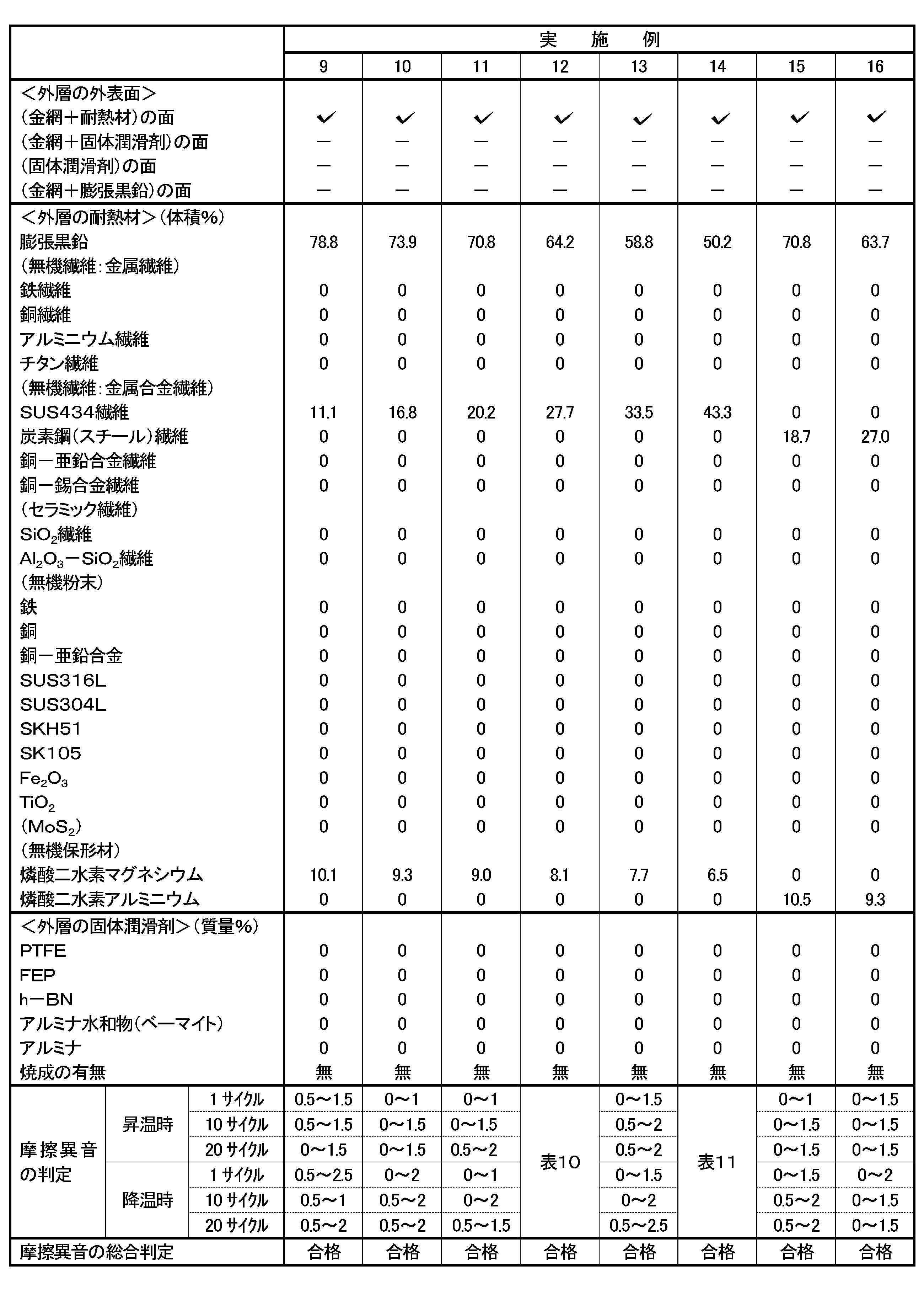
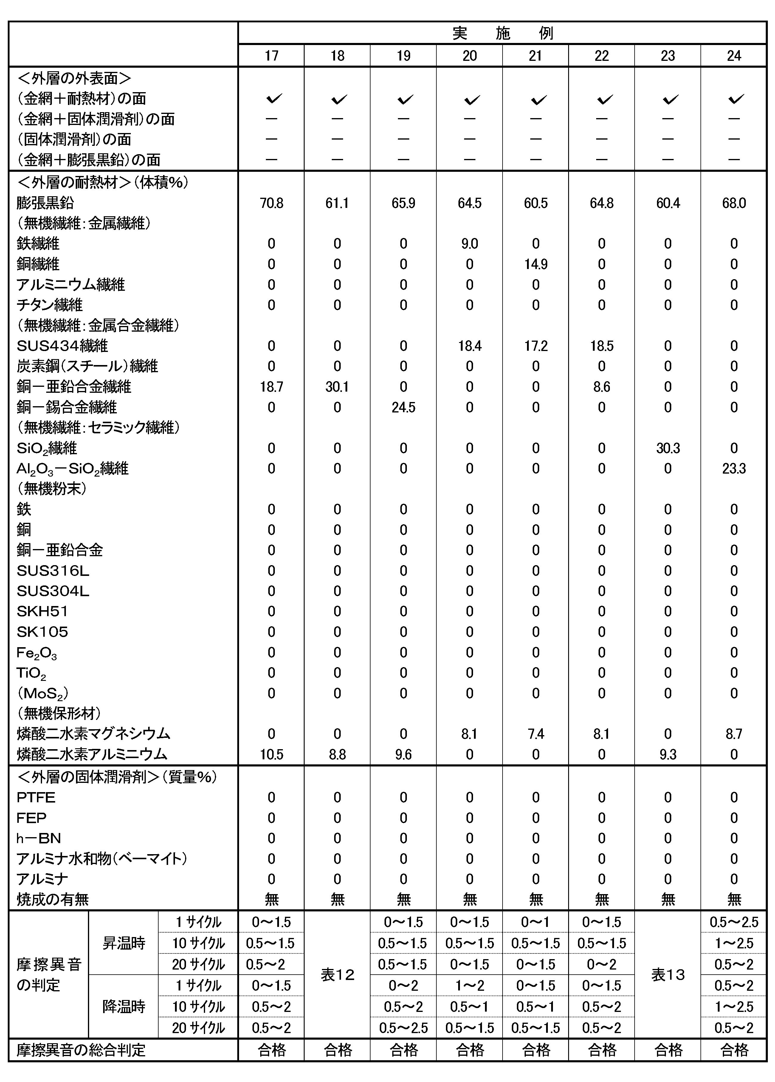
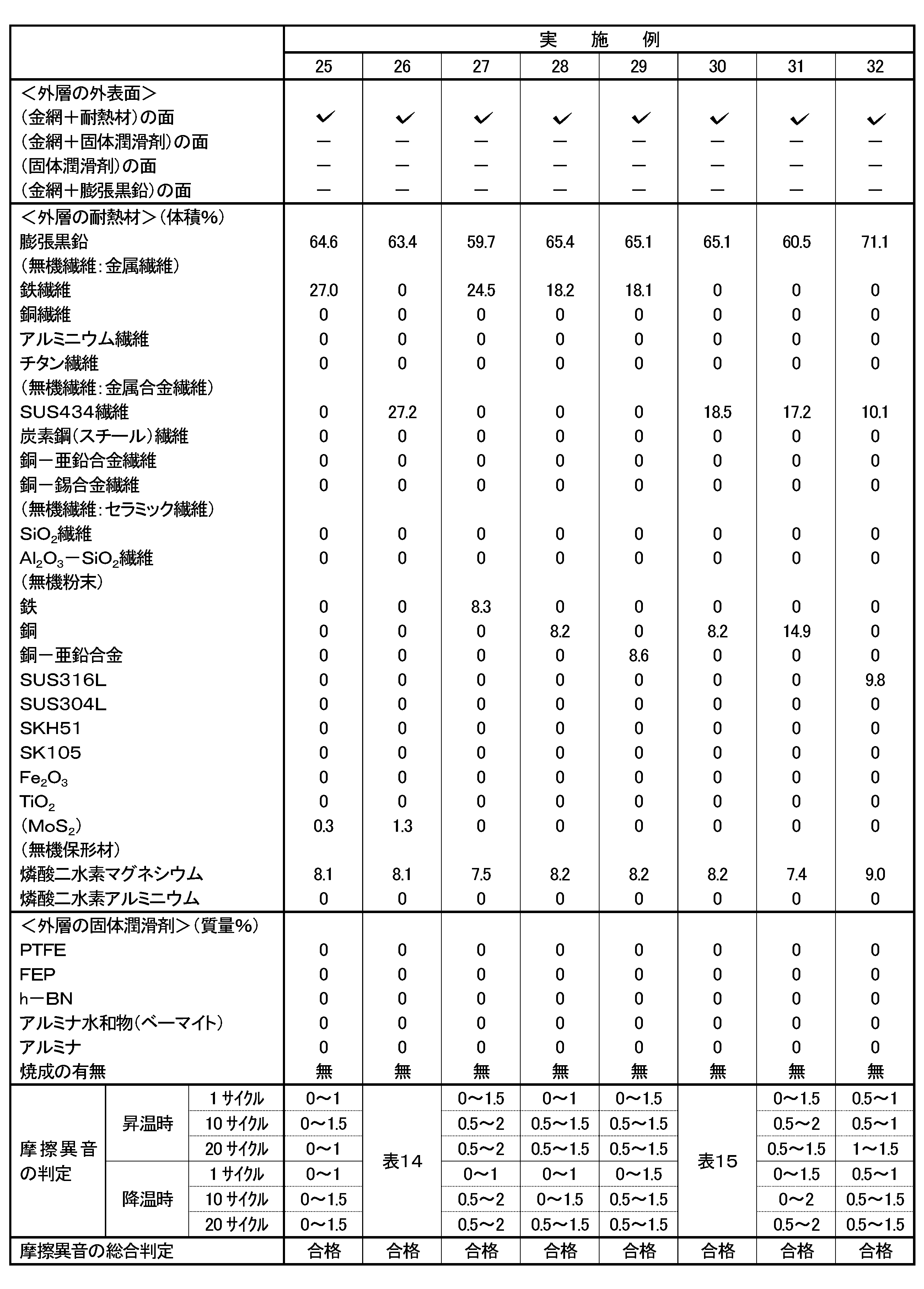
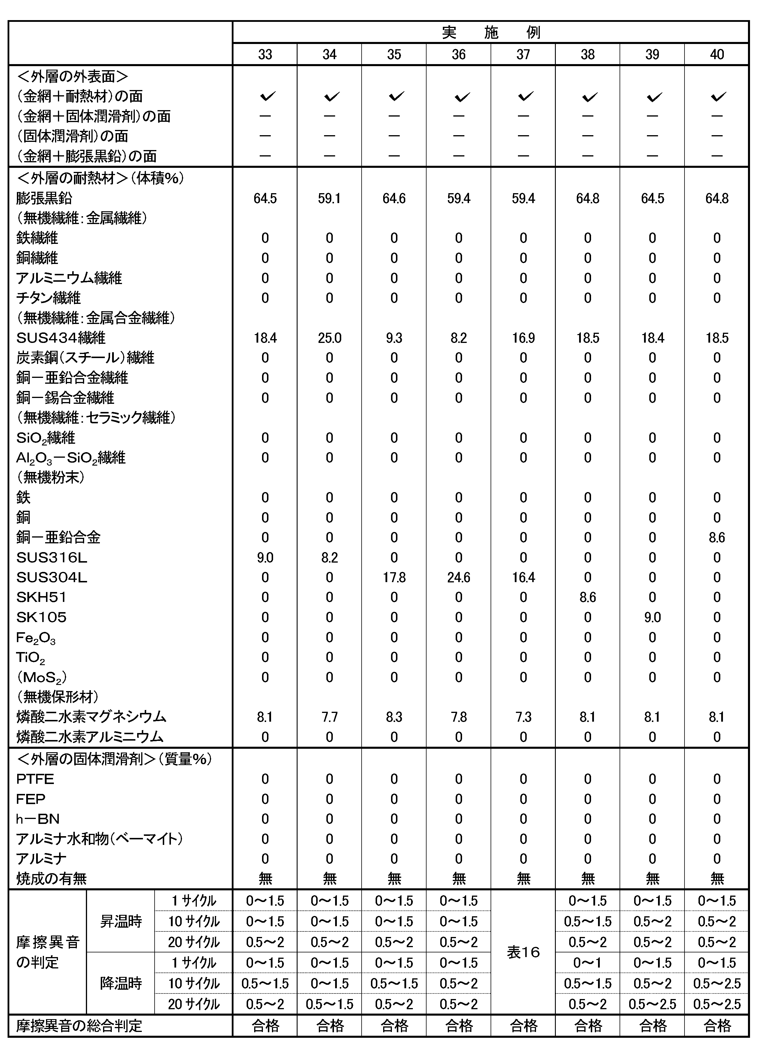
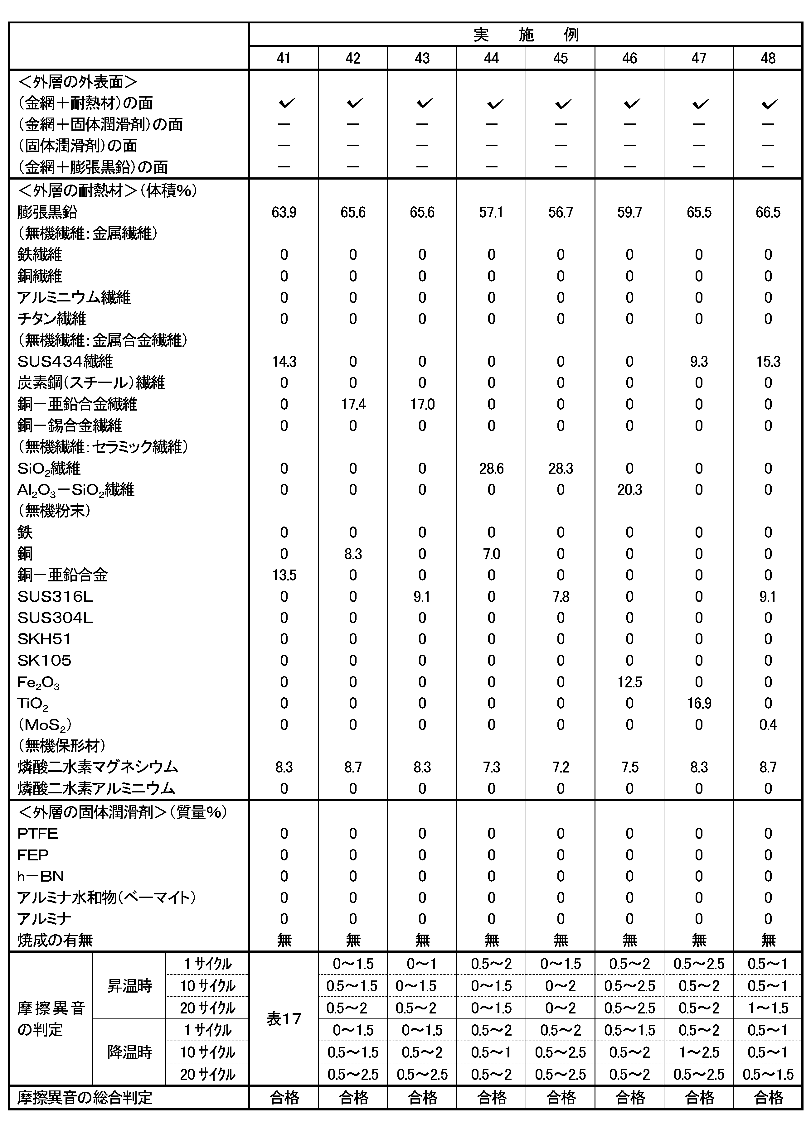
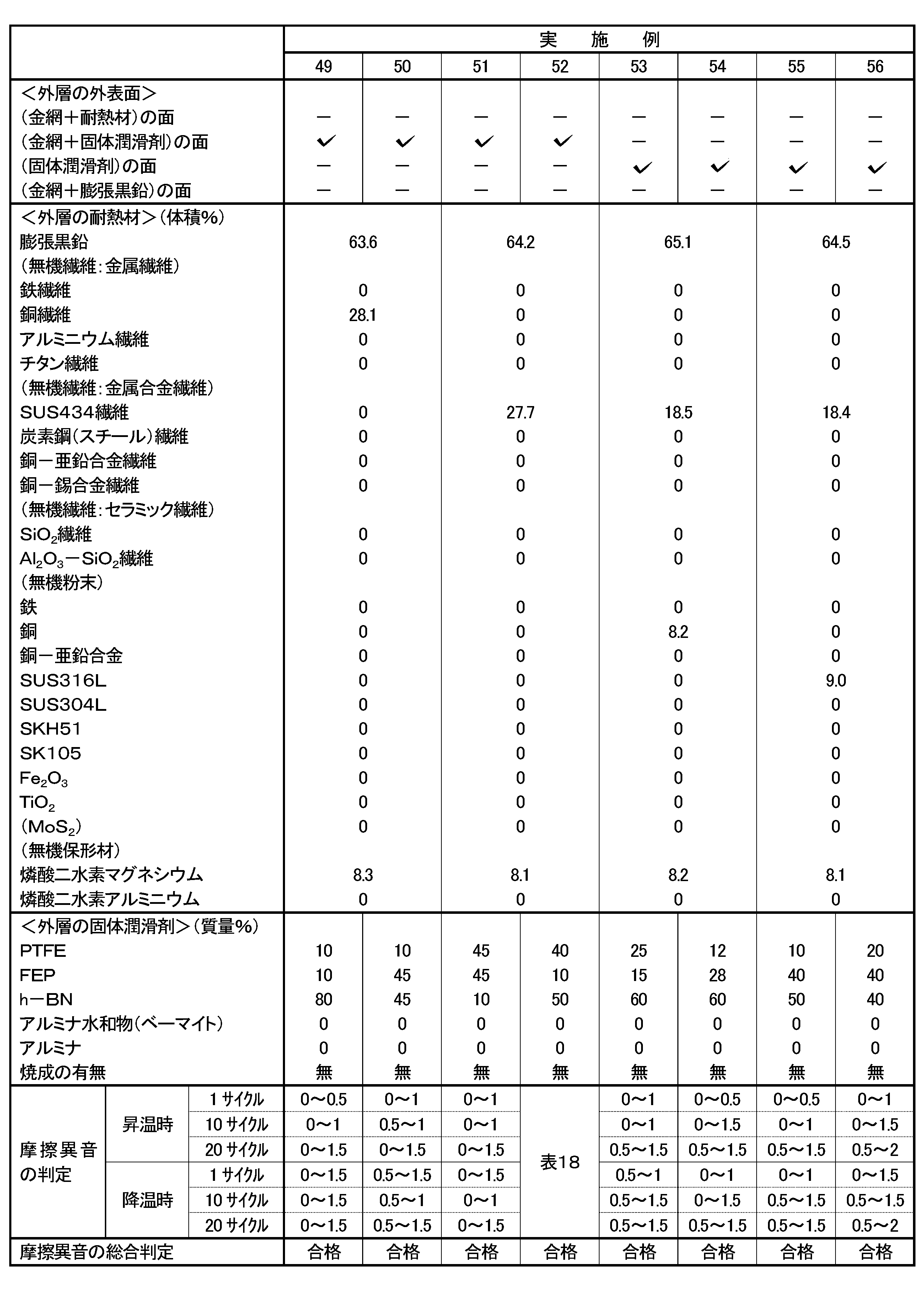
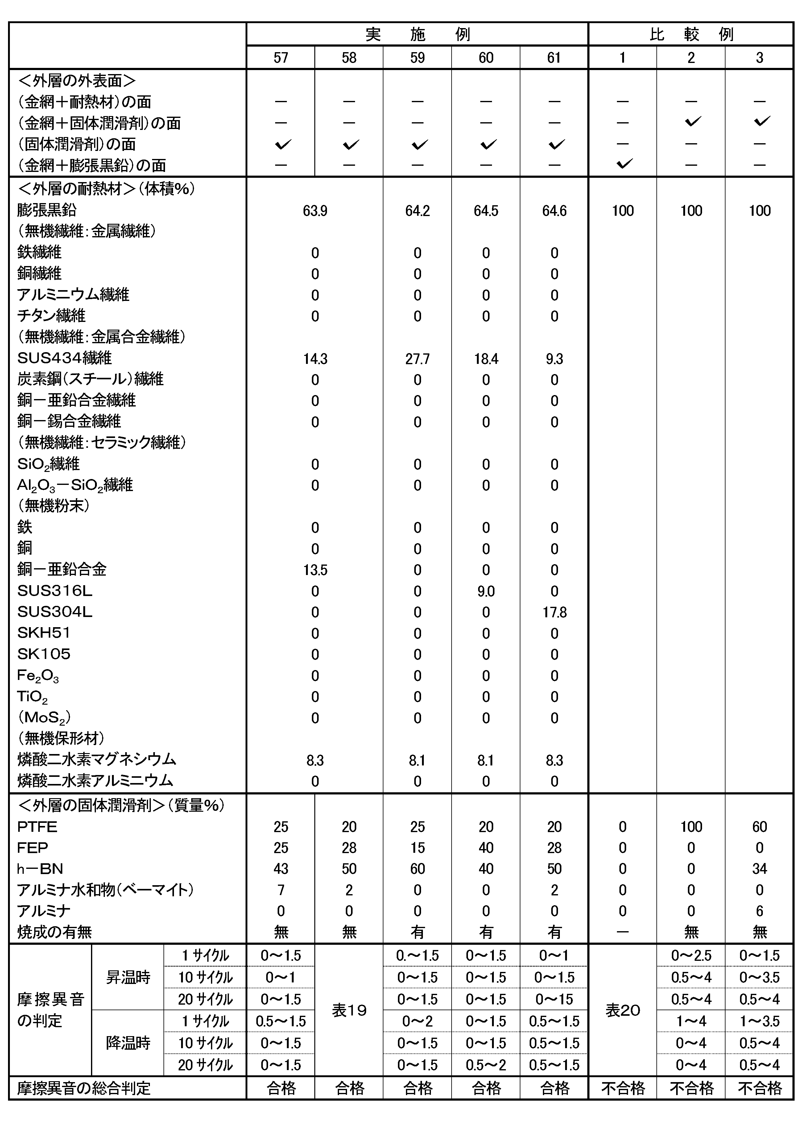


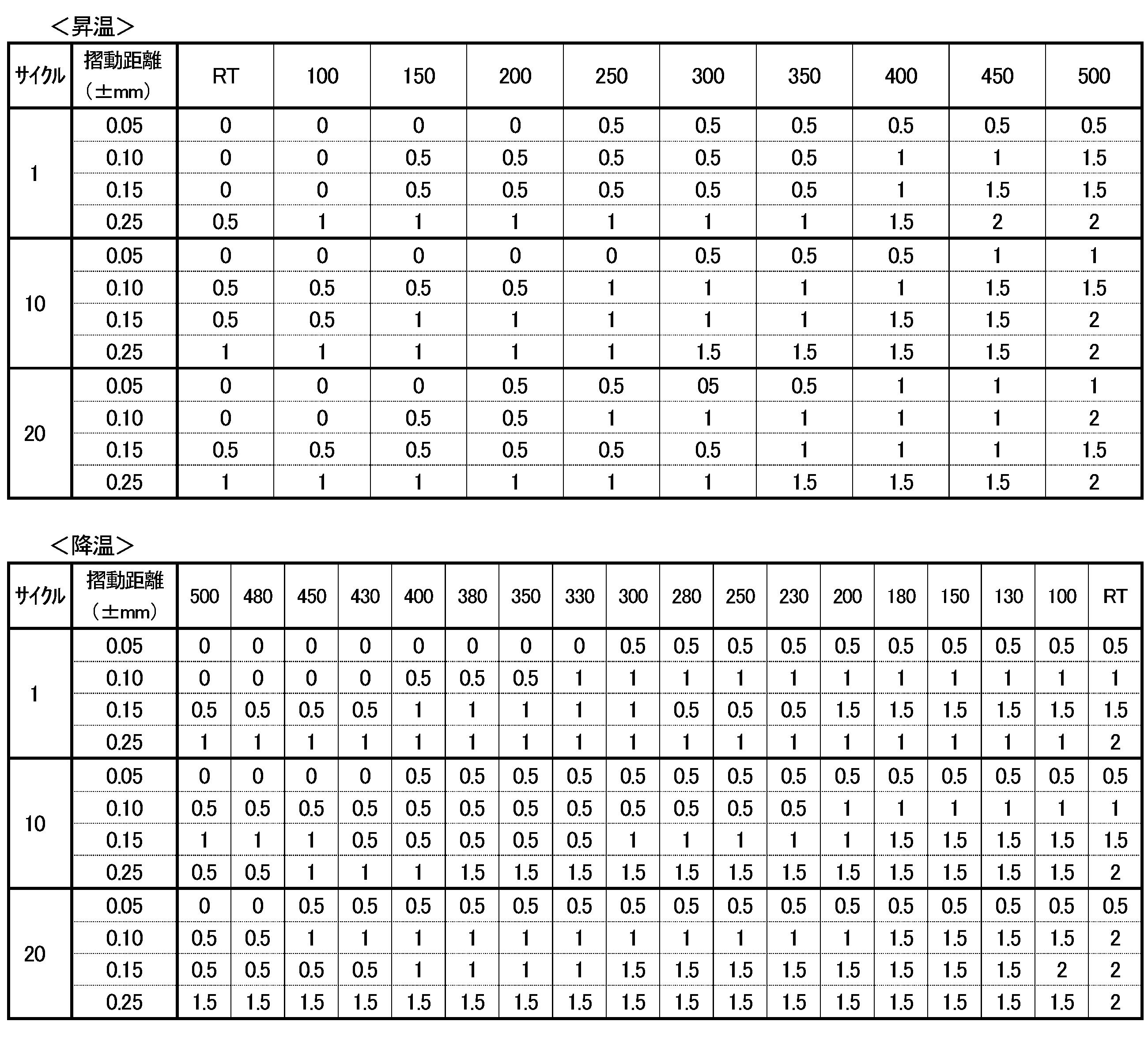


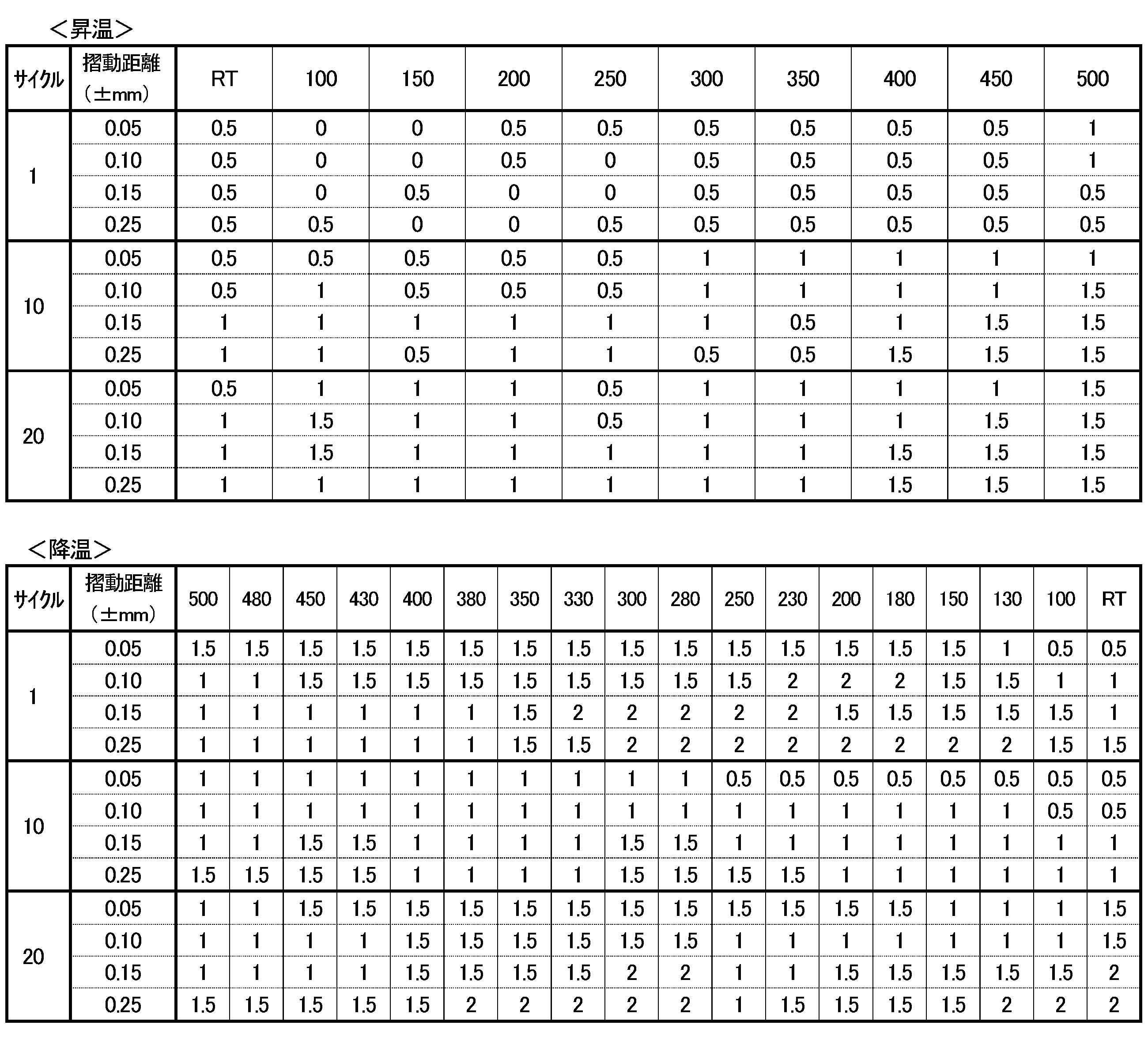


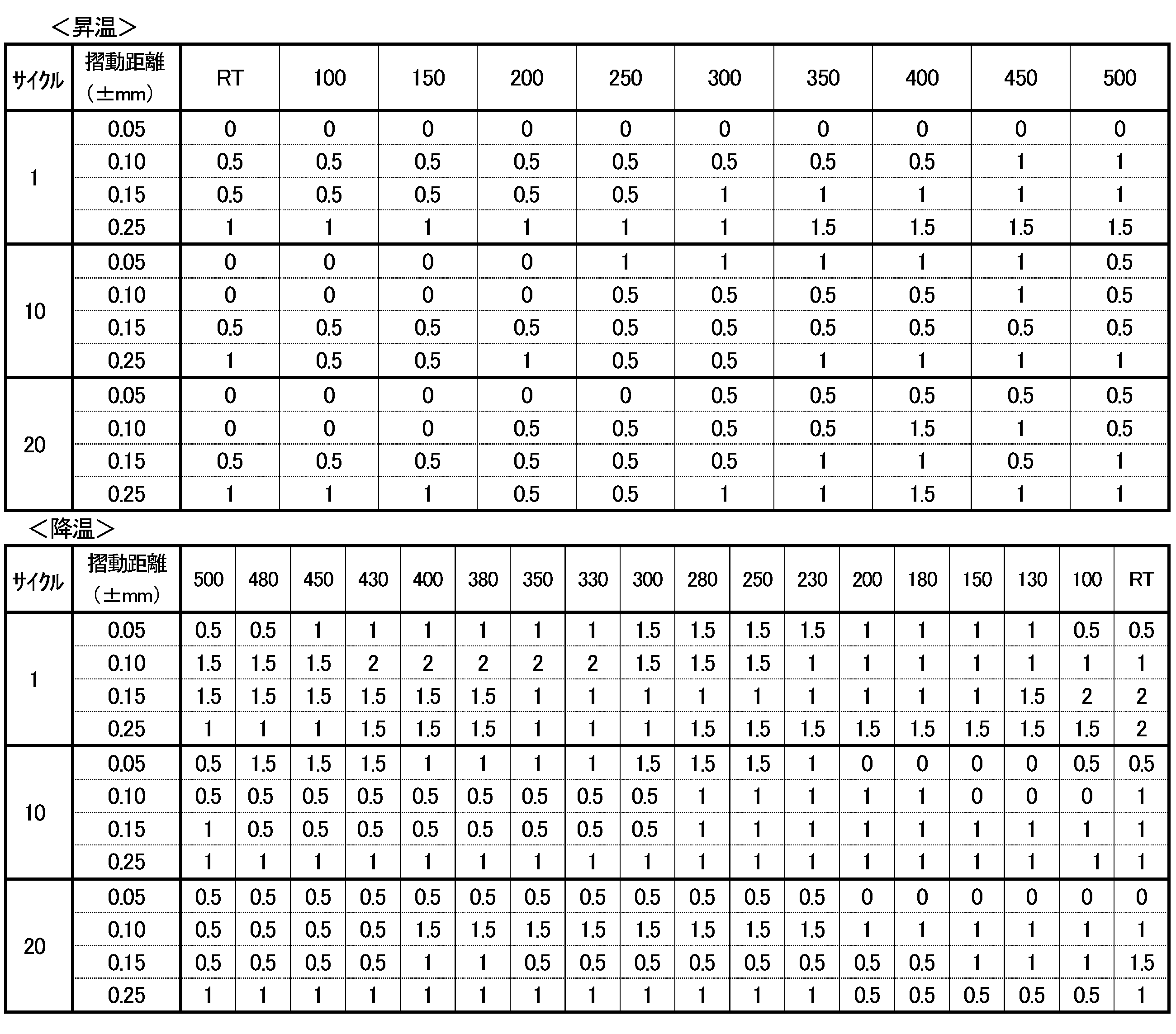

5、5a 金網
6 シート
12 重合体
14 混合物
30a、30b、30c、30d 外層形成部材
31 被覆層(固体潤滑剤)
34 予備円筒成形体
43 円筒内面
44 部分凸球状面
45、46 環状端面
47 球帯状基体
49 外層
50 球帯状シール体
51 外表面
6 シート
12 重合体
14 混合物
30a、30b、30c、30d 外層形成部材
31 被覆層(固体潤滑剤)
34 予備円筒成形体
43 円筒内面
44 部分凸球状面
45、46 環状端面
47 球帯状基体
49 外層
50 球帯状シール体
51 外表面
Claims (26)
- 円筒内面、部分凸球状面並びに部分凸球状面の大径側及び小径側の環状端面によって規定されていると共に排気管継手に用いられる球帯状シール体であって、球帯状基体と、この球帯状基体に一体的に形成されていると共に該部分凸球状面を構成している平滑な外表面を有した外層とを備えており、球帯状基体は、圧縮された金網からなる補強材と、この補強材の金網の網目を充填し、且つ、補強材と混在一体化されていると共に圧縮された膨張黒鉛を含む耐熱材とを具備しており、外層は、圧縮された金網からなる補強材と、この補強材の金網の網目を充填し、且つ、当該補強材と混在一体化されていると共に圧縮された少なくとも膨張黒鉛、無機繊維及び無機保形材を含んでいる耐熱材とを具備している球帯状シール体。
- 無機繊維は、金属繊維、金属合金繊維及びセラミックス繊維のうちの少なくとも一つから選択されている請求項1に記載の球帯状シール体。
- 金属繊維は、鉄繊維、銅繊維、アルミニウム繊維、亜鉛繊維、ニッケル繊維、クロム繊維、チタン繊維のうちの少なくとも一つから選択されている請求項2に記載の球帯状シール体。
- 金属合金繊維は、鉄合金繊維、銅合金繊維、アルミニウム-ニッケル合金繊維、ニッケル-錫合金繊維及びチタン合金繊維のうちの少なくとも一つから選択されている請求項2に記載の球帯状シール体。
- セラミックス繊維は、シリカ繊維、シリカ化合物繊維、アルミナ-シリカ繊維及びほう酸アルミニウム繊維のうちの少なくとも一つから選択されている請求項2から4のいずれか一項に記載の球帯状シール体。
- 無機保形材は、燐酸二水素アルミニウム、燐酸水素アルミニウム、燐酸二水素マグネシウム、燐酸水素マグネシウム、燐酸二水素カルシウム、燐酸水素カルシウム、燐酸、二酸化ケイ素(SiO2)及びアルミナ水和物のうちの少なくとも一つから選択されている請求項1から5のいずれか一項に記載の球帯状シール体。
- 外層の耐熱材における膨張黒鉛と無機繊維及び無機保形材との配合割合は、質量比で1:0.5~3:0.05~0.3である請求項1から6のいずれか一項に記載の球帯状シール体。
- 外層の耐熱材は、更に無機粉末を含んでいる請求項1から7に記載の球帯状シール体。
- 無機粉末は、金属粉末、金属合金粉末及びセラミックス粉末のうちの少なくとも一つから選択されている請求項8に記載の球帯状シール体。
- 金属粉末は、鉄粉末、銅粉末、ニッケル粉末、アルミニウム粉末、クロム粉末及びチタン粉末のうちの少なくとも一つから選択されている請求項9に記載の球帯状シール体。
- 金属合金粉末は、鉄合金粉末、銅合金粉末、アルミニウム合金粉末及びニッケル合金粉末のうちの少なくとも一つから選択されている請求項9又は10に記載の球帯状シール体。
- セラミックス粉末は、二酸化ケイ素粉末、酸化鉄粉末、四酸酸化鉄粉末、酸化チタン粉末、酸化ジルコニウム粉末、酸化マグネシウム粉末、ムライト粉末、ステアタイト粉末、フォルステライト粉末及びγ-アルミナ粉末のうちの少なくとも一つから選択されている請求項9から11のいずれか一項に記載の球帯状シール体。
- 外層の耐熱材における膨張黒鉛と無機繊維と無機粉末と無機保形材との配合割合は、質量比で1:0.5~3:0.5~3:0.05~0.3である請求項7から10のいずれか一項に記載の球帯状シール体。
- 外層の耐熱材は、更に二硫化モリブデン、二硫化タングステン及び六方晶窒化硼素のうちの少なくとも一つを含んでいる請求項1から13のいずれか一項に記載の球帯状シール体。
- 外層の耐熱材における二硫化モリブデン、二硫化タングステン又は六方晶窒化硼素の配合割合は、質量比で0.01~0.05である請求項14に記載の球帯状シール体。
- 外層の外表面には、少なくとも外層の耐熱材からなる面と外層の補強材からなる面とが混在している請求項1から15のいずれか一項に記載の球帯状シール体。
- 外層は、外層の補強材の金網の網目に充填されていると共に当該補強材及び外層の耐熱材と混在一体化された固体潤滑剤を更に具備している請求項1から15のいずれか一項に記載の球帯状シール体。
- 外層の外表面には、少なくとも外層の補強材からなる面と固体潤滑剤からなる面とが混在している請求項17に記載の球帯状シール体。
- 外層は、外層の補強材及び耐熱材を具備していると共に球帯状基体に一体的に形成された中間層と、この中間層を覆って当該中間層に被着形成されていると共に固体潤滑剤を含んでいる被覆層とを具備しており、外層の外表面は、被覆層の固体潤滑剤の面からなっている請求項1から15のいずれか一項に記載の球帯状シール体。
- 固体潤滑剤は、四フッ化エチレン樹脂、テトラフルオロエチレン-ヘキサフルオロプロピレン共重合体及び六方晶窒化硼素を含んでいる請求項17から19のいずれか一項に記載の球帯状シール体。
- 四フッ化エチレン樹脂、テトラフルオロエチレン-ヘキサフルオロプロピレン共重合体及び六方晶窒化硼素の固体潤滑剤での組成割合は、四フッ化エチレン樹脂、テトラフルオロエチレン-ヘキサフルオロプロピレン共重合体及び六方晶窒化硼素の三元系組成図において、四フッ化エチレン樹脂10質量%、テトラフルオロエチレン-ヘキサフルオロプロピレン共重合体10質量%及び六方晶窒化硼素80質量%とする組成点、四フッ化エチレン樹脂10質量%、テトラフルオロエチレン-キサフルオロプロピレン共重合体45質量%及び六方晶窒化硼素45質量%とする組成点、四フッ化エチレン樹脂45質量%、テトラフルオロエチレン-キサフルオロプロピレン共重合体45質量%及び六方晶窒化硼素10質量%とする組成点並びに四フッ化エチレン樹脂40質量%、テトラフルオロエチレン-ヘキサフルオロプロピレン共重合体10質量%及び六方晶窒化硼素50質量%とする組成点を頂点とする四角形で境界付けられる領域内に相当する数値範囲内にある請求項20に記載の球帯状シール体。
- 四フッ化エチレン樹脂、テトラフルオロエチレン-ヘキサフルオロプロピレン共重合体及び六方晶窒化硼素の固体潤滑剤での組成割合は、四フッ化エチレン樹脂、テトラフルオロエチレン-ヘキサフルオロプロピレン共重合体及び六方晶窒化硼素の三元系組成図において、四フッ化エチレン樹脂25質量%、テトラフルオロエチレン-ヘキサフルオロプロピレン共重合体15質量%及び六方晶窒化硼素60質量%とする組成点、四フッ化エチレン樹脂12質量%、テトラフルオロエチレン-ヘキサフルオロプロピレン共重合体28質量%及び六方晶窒化硼素60質量%とする組成点、四フッ化エチレン樹脂10質量%、テトラフルオロエチレン-ヘキサフルオロプロピレン共重合体40質量%及び六方晶窒化硼素50質量%とする組成点、四フッ化エチレン樹脂20質量%、テトラフルオロエチレン-ヘキサフルオロプロピレン共重合体40質量%及び六方晶窒化硼素40質量%とする組成点、四フッ化エチレン樹脂38質量%、テトラフルオロエチレン-ヘキサフルオロプロピレン共重合体22質量%及び六方晶窒化硼素40質量%とする組成点並びに四フッ化エチレン樹脂35質量%、テトラフルオロエチレン-ヘキサフルオロプロピレン共重合体15質量%及び六方晶窒化硼素50質量%とする組成点を頂点とする六角形で境界付けられる領域内に相当する数値範囲内にある請求項20又は21に記載の球帯状シール体。
- 固体潤滑剤は、アルミナ水和物を20質量%以下更に含有する請求項20から22のいずれか一項に記載の球帯状シール体。
- 固体潤滑剤は、未焼成である請求項19から23のいずれか一項に記載の球帯状シール体。
- 固体潤滑剤は、焼成されている請求項19から23のいずれか一項に記載の球帯状シール体。
- 球帯状基体の耐熱材及び外層の耐熱材のうちの少なくとも一方は、酸化抑制剤としての五酸化燐0.05~5質量%及び燐酸塩0.1~16.0質量%のうちの少なくとも一方を含んでいる請求項1から25のいずれか一項に記載の球帯状シール体。
Applications Claiming Priority (2)
| Application Number | Priority Date | Filing Date | Title |
|---|---|---|---|
| JP2014070601A JP6427916B2 (ja) | 2014-03-28 | 2014-03-28 | 球帯状シール体 |
| JP2014-070601 | 2014-03-28 |
Publications (1)
| Publication Number | Publication Date |
|---|---|
| WO2015146015A1 true WO2015146015A1 (ja) | 2015-10-01 |
Family
ID=54194569
Family Applications (1)
| Application Number | Title | Priority Date | Filing Date |
|---|---|---|---|
| PCT/JP2015/001250 Ceased WO2015146015A1 (ja) | 2014-03-28 | 2015-03-09 | 球帯状シール体 |
Country Status (2)
| Country | Link |
|---|---|
| JP (1) | JP6427916B2 (ja) |
| WO (1) | WO2015146015A1 (ja) |
Cited By (2)
| Publication number | Priority date | Publication date | Assignee | Title |
|---|---|---|---|---|
| CN106634834A (zh) * | 2016-12-20 | 2017-05-10 | 湖北飞龙摩擦密封材料股份有限公司 | 摩擦材料及摩擦制品 |
| CN109854650A (zh) * | 2019-03-27 | 2019-06-07 | 山东百德瑞轨道交通科技有限公司 | 一种高速列车闸片用摩擦单元及其制备方法 |
Families Citing this family (1)
| Publication number | Priority date | Publication date | Assignee | Title |
|---|---|---|---|---|
| CN113101573B (zh) * | 2021-04-13 | 2022-01-18 | 宁波大学 | 一种通过可磨耗封严涂层密封的灭火器及其阀门 |
Citations (3)
| Publication number | Priority date | Publication date | Assignee | Title |
|---|---|---|---|---|
| JPS6440784A (en) * | 1987-08-07 | 1989-02-13 | Oiles Industry Co Ltd | Sealing body for spherical pipe joint and manufacture thereof |
| JPH06123362A (ja) * | 1992-10-12 | 1994-05-06 | Oiles Ind Co Ltd | 球帯状シール体 |
| JPH0941959A (ja) * | 1995-07-26 | 1997-02-10 | Mitsubishi Motors Corp | シールリング |
Family Cites Families (1)
| Publication number | Priority date | Publication date | Assignee | Title |
|---|---|---|---|---|
| JPS59115816U (ja) * | 1983-01-26 | 1984-08-04 | 中央発條株式会社 | 自動車排気管ジヨイント装置 |
-
2014
- 2014-03-28 JP JP2014070601A patent/JP6427916B2/ja active Active
-
2015
- 2015-03-09 WO PCT/JP2015/001250 patent/WO2015146015A1/ja not_active Ceased
Patent Citations (3)
| Publication number | Priority date | Publication date | Assignee | Title |
|---|---|---|---|---|
| JPS6440784A (en) * | 1987-08-07 | 1989-02-13 | Oiles Industry Co Ltd | Sealing body for spherical pipe joint and manufacture thereof |
| JPH06123362A (ja) * | 1992-10-12 | 1994-05-06 | Oiles Ind Co Ltd | 球帯状シール体 |
| JPH0941959A (ja) * | 1995-07-26 | 1997-02-10 | Mitsubishi Motors Corp | シールリング |
Cited By (3)
| Publication number | Priority date | Publication date | Assignee | Title |
|---|---|---|---|---|
| CN106634834A (zh) * | 2016-12-20 | 2017-05-10 | 湖北飞龙摩擦密封材料股份有限公司 | 摩擦材料及摩擦制品 |
| CN109854650A (zh) * | 2019-03-27 | 2019-06-07 | 山东百德瑞轨道交通科技有限公司 | 一种高速列车闸片用摩擦单元及其制备方法 |
| CN109854650B (zh) * | 2019-03-27 | 2020-11-13 | 山东百德瑞轨道交通科技有限公司 | 一种高速列车闸片用摩擦单元及其制备方法 |
Also Published As
| Publication number | Publication date |
|---|---|
| JP6427916B2 (ja) | 2018-11-28 |
| JP2015190609A (ja) | 2015-11-02 |
Similar Documents
| Publication | Publication Date | Title |
|---|---|---|
| CN101889159B (zh) | 球形环密封件及其制造方法 | |
| JP5972991B2 (ja) | 球帯状シール体及びその製造方法 | |
| CN104081104B (zh) | 球形环密封件 | |
| JPH10220584A (ja) | 球帯状シール体ならびにその製造方法 | |
| JP5771945B2 (ja) | 球帯状シール体 | |
| JP6427916B2 (ja) | 球帯状シール体 | |
| CA2831131C (en) | Spherical annular seal member and method of manufacturing the same | |
| JP6314398B2 (ja) | 球帯状シール体 | |
| JP6003062B2 (ja) | 排気管球面継手 | |
| TWI543889B (zh) | 球帶狀密封體 | |
| TW201447148A (zh) | 球帶狀密封體 | |
| JP2016017462A (ja) | 排気管球面継手 | |
| JP2015117743A (ja) | 球帯状シール体 | |
| JP5978989B2 (ja) | 球帯状シール体 |
Legal Events
| Date | Code | Title | Description |
|---|---|---|---|
| 121 | Ep: the epo has been informed by wipo that ep was designated in this application |
Ref document number: 15768353 Country of ref document: EP Kind code of ref document: A1 |
|
| NENP | Non-entry into the national phase | ||
| 122 | Ep: pct application non-entry in european phase |
Ref document number: 15768353 Country of ref document: EP Kind code of ref document: A1 |