WO2015145853A1 - 掃除ユニット及びそれを利用した掃除機 - Google Patents
掃除ユニット及びそれを利用した掃除機 Download PDFInfo
- Publication number
- WO2015145853A1 WO2015145853A1 PCT/JP2014/079337 JP2014079337W WO2015145853A1 WO 2015145853 A1 WO2015145853 A1 WO 2015145853A1 JP 2014079337 W JP2014079337 W JP 2014079337W WO 2015145853 A1 WO2015145853 A1 WO 2015145853A1
- Authority
- WO
- WIPO (PCT)
- Prior art keywords
- dust
- cleaning unit
- dust collector
- unit
- stop command
- Prior art date
- Legal status (The legal status is an assumption and is not a legal conclusion. Google has not performed a legal analysis and makes no representation as to the accuracy of the status listed.)
- Ceased
Links
Images










Classifications
-
- A—HUMAN NECESSITIES
- A47—FURNITURE; DOMESTIC ARTICLES OR APPLIANCES; COFFEE MILLS; SPICE MILLS; SUCTION CLEANERS IN GENERAL
- A47L—DOMESTIC WASHING OR CLEANING; SUCTION CLEANERS IN GENERAL
- A47L9/00—Details or accessories of suction cleaners, e.g. mechanical means for controlling the suction or for effecting pulsating action; Storing devices specially adapted to suction cleaners or parts thereof; Carrying-vehicles specially adapted for suction cleaners
- A47L9/28—Installation of the electric equipment, e.g. adaptation or attachment to the suction cleaner; Controlling suction cleaners by electric means
-
- A—HUMAN NECESSITIES
- A47—FURNITURE; DOMESTIC ARTICLES OR APPLIANCES; COFFEE MILLS; SPICE MILLS; SUCTION CLEANERS IN GENERAL
- A47L—DOMESTIC WASHING OR CLEANING; SUCTION CLEANERS IN GENERAL
- A47L11/00—Machines for cleaning floors, carpets, furniture, walls, or wall coverings
- A47L11/40—Parts or details of machines not provided for in groups A47L11/02 - A47L11/38, or not restricted to one of these groups, e.g. handles, arrangements of switches, skirts, buffers, levers
- A47L11/4036—Parts or details of the surface treating tools
- A47L11/4041—Roll shaped surface treating tools
-
- A—HUMAN NECESSITIES
- A47—FURNITURE; DOMESTIC ARTICLES OR APPLIANCES; COFFEE MILLS; SPICE MILLS; SUCTION CLEANERS IN GENERAL
- A47L—DOMESTIC WASHING OR CLEANING; SUCTION CLEANERS IN GENERAL
- A47L11/00—Machines for cleaning floors, carpets, furniture, walls, or wall coverings
- A47L11/40—Parts or details of machines not provided for in groups A47L11/02 - A47L11/38, or not restricted to one of these groups, e.g. handles, arrangements of switches, skirts, buffers, levers
- A47L11/4036—Parts or details of the surface treating tools
- A47L11/4047—Wound-up or endless cleaning belts
-
- A—HUMAN NECESSITIES
- A47—FURNITURE; DOMESTIC ARTICLES OR APPLIANCES; COFFEE MILLS; SPICE MILLS; SUCTION CLEANERS IN GENERAL
- A47L—DOMESTIC WASHING OR CLEANING; SUCTION CLEANERS IN GENERAL
- A47L13/00—Implements for cleaning floors, carpets, furniture, walls, or wall coverings
- A47L13/10—Scrubbing; Scouring; Cleaning; Polishing
- A47L13/40—Cleaning implements actuated by electrostatic attraction; Devices for cleaning same; Magnetic cleaning implements
Definitions
- the present invention relates to a cleaning unit and a vacuum cleaner using the same.
- Patent Document 1 Japanese Patent No. 3261342
- This electrostatic cleaner employs a charging roller structure as shown in FIG.
- dust 98 on the floor surface 99 is adsorbed to the charging roller 91 and removed.
- the dust etc. 98 on the charging roller 91 is removed by bringing the scraper 92 into contact with the charging roller 91, and the removed dust etc. 98 is collected by the collecting unit.
- a method of collecting from the opening 95 of the 93 to the inside of the collecting unit 93 is adopted.
- the electrostatic cleaner has the advantages that there is no noise caused by the rotation of the motor and fan unlike the vacuum suction type cleaner, and that the indoor air is not contaminated by the exhaust.
- an object of the present invention is to provide a cleaning unit that can prevent the floor surface after cleaning from being soiled again and prevent the accumulation of dust inside and causing malfunctions such as malfunctions.
- the cleaning unit of the present invention comprises: A dust collector that transports the dust, A driving device for driving the dust collector; A collection unit that collects dust attached to the dust collector; An operation unit to which a stop command is input; When receiving the stop command from the operation unit, the drive device is provided with a stop control unit that controls the drive device to continue driving until a certain condition is satisfied without immediately stopping the drive device. .
- the certain condition is that a predetermined time elapses after receiving the stop command, or that the dust collector is driven by a predetermined amount after receiving the stop command.
- a dust detector for detecting the amount of dust attached to the dust collector is arranged in the cleaning unit of one embodiment.
- the certain condition is that the amount of dust detected by the dust detector is equal to or less than a predetermined amount.
- the stop control unit when receiving the stop command from the operation unit, makes the driving speed of the dust collector faster than the driving speed of the dust collector before receiving the stop command.
- the dust collector has a chargeable charging layer, And a charging device for charging the charging layer,
- the stop control unit stops the charging device when receiving the stop command from the operation unit.
- the dust collector is A first rotating body; A second rotating body;
- the belt comprises a belt wound around the first rotating body and the second rotating body and having dust attached thereto.
- the vacuum cleaner of the present invention is A cleaning unit as described above; And a power feeding device for feeding power to the cleaning unit.
- the drive device when the stop control unit receives a stop command from the operation unit, the drive device is not immediately stopped, and control is performed so as to continue driving the drive device until a certain condition is satisfied. It is possible to prevent the floor surface after the cleaning from being soiled again, and to prevent the accumulation of dust inside and the occurrence of malfunctions such as malfunctions.
- FIG. It is a schematic sectional drawing of the cleaning unit which concerns on Embodiment 1 of this invention. It is a control block diagram of the cleaning unit. It is a figure for demonstrating the collection
- FIG. It is a schematic diagram which shows a state when a stop command is input into the operation button of the said cleaning unit. It is a schematic diagram which shows operation
- FIG. 1 It is a perspective view of the dust collector of the cleaning unit which concerns on the said Embodiment 2. It is a control block diagram of the cleaning unit according to the second embodiment. It is a flowchart for demonstrating the collection process at the time of a stop of the stop control part of the said cleaning unit. It is a schematic sectional drawing of the cleaning unit which concerns on Embodiment 3 of this invention. It is a control block diagram of the cleaning unit according to the third embodiment. It is a flowchart for demonstrating the collection process at the time of a stop of the stop control part of the cleaning unit which concerns on the said Embodiment 3. FIG. It is a schematic sectional drawing of the cleaning unit which concerns on Embodiment 4 of this invention.
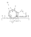
- FIG. 1 is a schematic cross-sectional view of the cleaning unit of the first embodiment.
- the cleaning unit 100 includes a dust collector 1 that conveys dust and the like on the outer peripheral surface, and a drive motor 5 that rotationally drives the dust collector 1. And a dust collection claw 71 for physically separating dust attached to the outer peripheral surface of the dust collector 1, and a collection container 72 for collecting the dust separated by the dust collection claw 71.
- the drive motor 5 is an example of the drive device of the present invention, and the dust collection pawl 71 and the recovery container 72 constitute the recovery unit 7 of the present invention.
- the dust collector 1 has a dust collector base 2 and a charged layer 3.
- the charging layer 3 is formed by coating or sheeting an insulating material such as phthalocyanine on the outer periphery of a cylindrical dust collector base 2 made of a conductor.
- the dust collector 1 is rotated clockwise with respect to the paper surface by a drive motor 5 at a predetermined interval so as not to contact the floor surface.
- the thickness of the charging layer 3 is 20 to 500 ⁇ m.
- the charging layer 3 is charged with static electricity by a charging device 6.
- the static electricity charged on the charging layer 3 is removed from the charging layer 3 by, for example, irradiation of light by the LED 10.
- PVK polyvinylcarbazole
- a layer containing polycrystalline silicon for example, Si deposition or coating film
- the drive motor 5 is disposed inside the dust collector base 2. Thus, by arranging the drive motor 5 inside the dust collector base 2, it is possible to make it difficult for the user of the cleaning unit 100 to hear the rotation sound generated when the dust collector base 2 rotates. .
- the charging device 6 is provided close to the charging layer 3 of the dust collector 1.
- the charging device 6 has an opening only on the surface facing the dust collector 1, and is made of a conductive cover 61 covering the other surface, a grid 63 attached to the opening facing the dust collector 1, tungsten, and the like.
- a corona wire 62 accommodated in the conductive cover 61.
- the corona wire 62 is held while being insulated from the conductive cover 61.
- the corona wire 62 is connected to the output terminal of a high voltage generating circuit as an applying means and a voltage of about 2 to 20 kV is applied to generate static electricity in the charging layer 3 and charge the charging layer 3. .
- a plurality of LEDs 10 are provided in the vicinity of the charging layer 3 of the dust collector 1. These LEDs 10 are arranged along the rotational axis direction of the dust collector 1.
- the garbage collection pawl 71 is made of rubber or the like. One end of the dust collection pawl 71 is attached to the collection container 72.
- the dust collecting claw 71 is provided so that dust adhering to the outer peripheral surface of the charged layer 3 of the dust collector 1 is peeled off from the charged layer 3 and scraped off into the collection container 72.
- the collection container 72 is provided with an operation button 51 for inputting a start command for starting the cleaning unit 100, a stop command for stopping the cleaning unit 100, and the like.
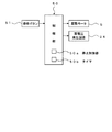
- FIG. 2 is a control block diagram of the cleaning unit 100.
- the control unit 50 includes a microcomputer, an input / output circuit, and the like, and includes a timer 50b.
- the control part 50 is arrange
- the control unit 50 is connected with an operation button 51, a drive motor 5, a charging device 6, and an LED 10.
- the control unit 50 receives a start command, a stop command, or the like from the operation button 51.
- the control unit 50 controls the drive motor 5, the charging device 6, and the LED 10 according to a predetermined program based on a start command, a stop command, and the like.
- the control unit 50 includes a stop control unit 50 a that controls the drive motor 5 when a stop command is input from the operation button 51.
- FIG. 3 is a diagram for explaining a collection method in which the cleaning unit 100 collects dust such as dust D.
- the dust collector 1 is rotated by a drive motor 5 in the direction of the arrow in the figure.
- the charged layer 3 of the dust collector 1 charged by the charging device 6 and charged with static electricity approaches the floor surface 13 by the rotation of the dust collector 1.
- the cleaning unit 100 including the dust collector 1 is assumed to move in parallel to the floor surface 13 to the left in the drawing.
- dust D or the like on the floor surface 13 is attracted by static electricity of the charging layer 3 and is separated from the floor surface 13 and adheres to the outer peripheral surface of the charging layer 3.
- the dust collector 1 rotates with the dust D and the like attached to the outer peripheral surface of the charging layer 3 and conveys the dust D and the like. Thereafter, the dust collector 1 is irradiated with light from the LED 10.
- FIGS. 4 to 6 are diagrams for explaining the recovery process when the cleaning unit 100 is stopped when the cleaning unit 100 is stopped in the first embodiment of the present invention.
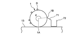
- FIG. 4 shows a state when a stop command is input to the operation button 51 (see FIG. 2) of the cleaning unit 100. As shown in FIG. 4, dust D or the like adheres to the outer peripheral surface of the dust collector 1.
- the stop control unit 50a (see FIG. 2) of the control unit 50 does not stop the drive motor 5 immediately but continues to drive the drive motor 5 until a certain condition is satisfied.
- the certain condition is that the dust collector 1 is rotated until a predetermined set time T1 elapses after receiving the stop command.
- the dust collector 1 contacts the dust collector 1 in the rotational direction of the dust collector 1 from the floor contact point 1A where the dust collector 1 and the floor surface 13 contact.
- the dust collecting pawl contact point 1B is rotated by a rotation angle ⁇ or more.
- FIG. 5 shows the operation of the cleaning unit 100 after receiving the stop command.
- the dust collector 1 is rotated by the drive motor 5 in the direction of the arrow in the figure.
- the dust D and the like adhering to the outer peripheral surface of the dust collector 1 are sequentially peeled off from the outer peripheral surface of the dust collector 1 by the dust collecting pawl 71, scraped off inside the recovery container 72 and recovered in the recovery container 72.
- FIG. 6 shows cleaning after rotating the dust collector 1 until a set time T1 elapses after receiving the stop command, that is, after rotating the dust collector 1 more than the rotation angle ⁇ after receiving the stop command.
- the state when the unit 100 is stopped is shown.
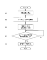
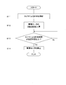
- step S1 when the control of the stop control unit 50a starts, the charging device 6 is stopped in step S1.
- step S2 timing by the timer 50b is started.
- step S3 the rotational speed of the drive motor 5 is increased by, for example, 50%, and the rotational speed of the dust collector 1 is increased.
- step S4 it is determined whether or not the time T of the timer 50b is equal to or longer than the set time T1. If it is determined in step S4 that the time count T is greater than or equal to the set time T1, the process proceeds to the next step S5. On the other hand, if it is determined in step S4 that the time count T is less than the set time T1, step S4 is performed again.
- step S5 the drive motor 5 is stopped and the dust collector 1 is stopped.
- the drive motor 5 when a stop command is received from the operation button 51, the drive motor 5 is not immediately stopped until a certain condition is satisfied, that is, the set time T1 has elapsed since the stop command was received. Until then, the drive motor 5 continues to be driven.
- a certain condition that is, the set time T1 has elapsed since the stop command was received.
- the drive motor 5 continues to be driven.
- the rotational speed of the dust collector 1 is increased during the stop-time recovery process, the dust attached to the dust collector 1 can be recovered in the recovery container 72 more quickly. Therefore, it is possible to prevent the dust adhering to the dust collector 1 from falling on the floor surface after cleaning or the inside of the cleaning unit 100. Moreover, the time required for the recovery process when the cleaning unit 100 is stopped can be shortened, and the convenience of the user of the cleaning unit 100 can be improved.
- the charging device 6 is stopped when the stop command is received from the operation button 51, even if the dust collector 1 is continuously driven after receiving the stop command, further dust is collected in the dust collector 1. It can prevent adhesion. Therefore, it is possible to further reduce the dust adhering to the dust collector 1 and more reliably prevent the floor surface that has been cleaned from being soiled again. Also, the dust accumulates inside the cleaning unit 100 and malfunctions such as malfunctions. Can be more reliably prevented.
- FIG. 8 is a diagram illustrating the configuration and operation of the cleaning unit 200 according to the second embodiment. The differences from the first embodiment will be described.
- the dust collector 21 has a dust collector base 2 and an adsorbing sheet 23, and a high voltage generation circuit 24 is provided.
- the charging device 6 and the LED 10 are not provided.
- the same or similar components as those of the cleaning unit 100 of the first embodiment shown in FIG. 3 are denoted by the same reference numerals as those of the components of FIG. Detailed description of the configuration and operation is omitted.
- the dust collector 21 is rotated clockwise with respect to the paper surface by a drive motor 5 disposed inside the dust collector base 2 at a constant interval so as not to contact the floor surface 13. It is designed to rotate.
- the high voltage generation circuit 24 is installed inside the dust collector base 2.
- the high voltage generation circuit 24 may be installed outside the dust collector base 2.
- FIG. 9 is a perspective view of the dust collector 21.
- the suction sheet 23 is provided on the outer periphery of the dust collector base 2.
- the suction sheet 23 has comb-shaped first and second electrode patterns 25 and 26.
- the first electrode pattern 25 and the second electrode pattern 26 are composed of the comb-shaped electrodes of the first electrode pattern 25 and the comb-shaped electrodes of the second electrode pattern 26 in the circumferential direction of the dust collector 21. Are arranged so as to be alternately located.
- the first electrode pattern 25 is connected to the high voltage wiring of the high voltage generation circuit 24.
- the second electrode pattern 26 is connected to the ground wiring of the high voltage generation circuit 24.
- the adsorption sheet 23 has a function of a charging layer that generates an adsorption force.
- FIG. 10 is a control block diagram of the cleaning unit 200. As shown in FIG. 10, a high voltage generation circuit 24 is connected to the control unit 50. The control unit 50 controls the drive motor 5 and the high voltage generation circuit 24 according to a predetermined program based on a start command, a stop command, or the like or a detection signal.
- the suction sheet 23 applied with a high voltage by the high voltage generation circuit 24 to generate the suction force approaches the floor surface 13 by the rotation of the dust collector 21.
- the cleaning unit 200 including the dust collector 21 moves in parallel to the floor surface 13 leftward on the paper surface.
- the dust D or the like on the floor surface 13 is separated from the floor surface 13 and adheres to the outer peripheral surface of the suction sheet 23 by the suction force of the suction sheet 23.
- the dust collector 21 rotates with the dust D attached to the outer peripheral surface of the suction sheet 23 and conveys the dust D and the like.
- step S11 when the control of the stop control unit 50a is started, the time measurement by the timer 50b is started in step S11.
- step S12 the rotational speed of the drive motor 5 is increased by, for example, 50%, and the rotational speed of the dust collector 1 is increased.
- step S13 it is determined whether or not the time measured by the timer 50b is equal to or longer than the set time T1. If it is determined in step S13 that the time count T is greater than or equal to the set time T1, the process proceeds to the next step S14. On the other hand, if it is determined in step S13 that the time count T is less than the set time T1, step S13 is performed again.
- step S14 the drive motor 5 is stopped and the dust collector 1 is stopped.
- the dust D and the like adhering to the outer peripheral surface of the dust collector 21 are all collected in the collection container 72 by the collection processing at the time of stop, and the dust such as dust D is cleaned. It does not fall into the finished floor or inside the cleaning unit 200. Therefore, it is possible to prevent the floor surface that has been cleaned from being soiled again, and to prevent dust from accumulating inside the cleaning unit 200 and causing malfunctions and the like.
- the high voltage generation circuit 24 is installed inside the dust collector base 2, so that the cleaning unit can be made compact.
- FIG. 12 is a diagram illustrating the configuration and operation of the cleaning unit 300 according to the third embodiment. The difference from the second embodiment will be described.
- the third embodiment is different in that a dust detector 31 is further provided.
- FIG. 12 the same or similar components as those of the cleaning unit 200 of the second embodiment shown in FIG. 8 are denoted by the same reference numerals as those of the components of FIG. Detailed description of the configuration and operation is omitted.
- the dust detector 31 is provided in the vicinity of the suction sheet 23 of the dust collector 21, and detects the amount of dust attached to the outer peripheral surface of the suction sheet 23.
- a laser displacement meter is used as the dust detector 31. If dust does not adhere to the outer peripheral surface of the suction sheet 23, the surface shape of the dust collector 21 measured from the displacement measured by the laser displacement meter becomes a smooth circumference. On the other hand, if a large amount of dust adheres to the outer peripheral surface of the suction sheet 23, the surface shape of the dust collector 21 measured from the displacement measured by the laser displacement meter becomes a circle with large irregularities. In other words, it is possible to detect the amount of dust attached to the outer peripheral surface of the suction sheet 23 by measuring the surface roughness of the dust collector 21 using a laser displacement meter.
- the dust detector 31 is not limited to a laser displacement meter.
- a camera may be used as a modification of the dust detector 31. If dust does not adhere to the outer peripheral surface of the suction sheet 23 of the dust collector 21, no dust appears in the image of the outer peripheral surface of the suction sheet 23 captured by the camera. On the other hand, if a large amount of dust adheres to the outer peripheral surface of the suction sheet 23, the dust appears in the image of the outer peripheral surface of the suction sheet 23 captured by the camera, and the amount of dust can be detected.
- FIG. 13 is a control block diagram of the cleaning unit 300. As shown in FIG. 13, the dust detector 31 is connected to the control unit 50. The control unit 50 controls the drive motor 5 and the high voltage generation circuit 24 according to a predetermined program based on a start command, a stop command, or the like, or a detection signal from the dust detector 31.
- step S21 when the control of the stop control unit 50a starts, in step S21, the rotational speed of the drive motor 5 is increased by 50% or more, and the rotational speed of the dust collector 1 is increased.
- step S22 based on the detection signal from the dust detector 31, whether or not the amount of dust attached to the outer peripheral surface of the suction sheet 23 of the dust collector 21 is equal to or less than a predetermined amount. Determine whether. If it is determined in step S22 that the amount of attached dust is equal to or less than a predetermined amount, the process proceeds to the next step S23. On the other hand, if it is determined in step S22 that the amount of attached dust is larger than a predetermined amount, step S22 is performed again.
- step S23 the drive motor 5 is stopped and the dust collector 21 is stopped.
- the drive motor 5 continues to be driven until the amount of dust in the dust collector 21 detected by the dust detector 31 is equal to or less than a predetermined amount in the collection processing at the time of stop. . For this reason, since the amount of dust in the dust collector 21 can be measured more accurately by the dust detector, dust can be more reliably removed from the dust collector 21. Accordingly, it is possible to more reliably prevent the floor surface that has been cleaned from being soiled again, and to more reliably prevent dust from accumulating inside the cleaning unit 300 and causing malfunctions and the like.
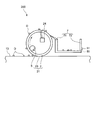
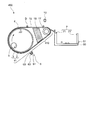
- FIG. 15 is a diagram illustrating the configuration and operation of the cleaning unit 400 of the fourth embodiment.
- the dust collector 410 includes a driving roller 11 as an example of a first rotating body, and a tension roller 17 as an example of a second rotating body.
- the difference is that the conveyor belt 15 is wound around the drive roller 11 and the tension roller 17 and adheres to dust.
- the same or similar components as those of the cleaning unit 100 of the first embodiment shown in FIG. 3 are denoted by the same reference numerals as those of the components of FIG. Detailed description of the configuration and operation is omitted.
- the drive roller 11 has a dust collector base 2 and a charging layer 3.
- the tension roller 17 is rotatably provided by a roller support member (not shown).
- the roller support member is locked and fixed by the support member 16.
- the conveyor belt 15 is driven by the rotation of the driving roller 11 and rotates around the driving roller 11 and the tension roller 17.
- the conveyor belt 15 needs to be made of a material that transmits the adsorption force generated from the charging layer 3 of the driving roller 11 to the dust on the floor surface, and has high wear resistance because it comes into contact with the floor surface and dust. A thing with high property is preferable. Considering such performance, the material and thickness of the conveyor belt 15 can be arbitrarily selected. However, since the suction force of the dust collector 410 decreases as the thickness of the transport belt 15 increases, a thickness of 0.2 mm or less is desirable.
- polyurethane (PU), polyvinyl chloride (PVC), ultra-high molecular weight polyethylene, or the like can be used as the material constituting the conveyor belt 15, but is not limited thereto. Any material that satisfies the wear properties and the like may be used.
- the conveyor belt 15 is driven by the driving roller 11 and rotates in the direction of the arrow in the figure.
- Dust D and the like are separated from the outer peripheral surface of the conveyor belt 15 by the dust collecting pawl 71 from the conveyor belt 15, scraped off inside the recovery container 72, and recovered in the recovery container 72. At this time, since the dust D and the like are separated from the charging layer 3 of the driving roller 11, physical peeling becomes easy. Furthermore, since the charge charged on the conveyor belt 15 is removed by the LED 10 or the like immediately before being transferred to the collection unit 7, dust D and the like can be peeled off from the conveyor belt 15 more effectively. The separated dust D and the like are finally collected by the collection unit 7 as in the first to third embodiments.
- the transport belt 15 is wound around the drive roller 11 and the tension roller 17. Therefore, the conveyor belt 15 can be easily replaced by simply attaching and detaching the conveyor belt 15 to and from the drive roller 11 and the tension roller 17.
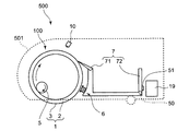
- FIG. 16 is a cross-sectional view of the vacuum cleaner 500 according to the fifth embodiment. This cleaner 500 uses the cleaning unit 100 of the first embodiment.
- a cleaning unit 100 and a battery 19 as an example of a power feeding device are mounted inside a housing (illustrated by a dotted line) 501 of the cleaner 500.
- the vacuum cleaner 500 functions by supplying power to the drive motor 5 of the cleaning unit 100 from the battery 19.
- the cleaner 500 of the fifth embodiment includes the cleaning unit 100, the operation and effect of the cleaning unit 100 are exhibited.
- FIG. 17 shows a cross-sectional view of the vacuum cleaner 600 of the sixth embodiment.
- This vacuum cleaner 600 uses the cleaning unit 200 of the second embodiment.
- a cleaning unit 200 and a battery 19 as an example of a power feeding device are mounted inside a housing (illustrated by a dotted line) 601 of the cleaner 600.
- the cleaner 600 When the battery 19 supplies power to the drive motor 5 of the cleaning unit 200, the cleaner 600 functions.
- the cleaner 600 of the sixth embodiment has the cleaning unit 200, the operation and effect of the cleaning unit 200 are exhibited.
- FIG. 18 is a cross-sectional view of the vacuum cleaner 700 according to the seventh embodiment. This vacuum cleaner 700 uses the cleaning unit 300 of the third embodiment.
- a cleaning unit 300 and a battery 19 as an example of a power feeding device are mounted inside a casing (illustrated by a dotted line) 701 of the vacuum cleaner 700.
- the vacuum cleaner 700 functions by supplying power from the battery 19 to the drive motor 5 of the cleaning unit 300.
- the vacuum cleaner 700 of the seventh embodiment includes the cleaning unit 300, the operation and effect of the cleaning unit 300 are exhibited.
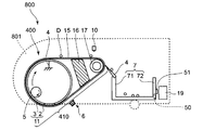
- FIG. 19 shows a cross-sectional view of the vacuum cleaner 800 of the eighth embodiment.
- This vacuum cleaner 800 uses the cleaning unit 400 of the fourth embodiment.
- a cleaning unit 400 and a battery 19 as an example of a power feeding device are mounted inside a housing (illustrated by a dotted line) 801 of the vacuum cleaner 800.
- the vacuum cleaner 800 functions by supplying power from the battery 19 to the drive motor 5 of the cleaning unit 400.
- the cleaner 800 of the eighth embodiment includes the cleaning unit 400, the operation and effect of the cleaning unit 400 are exhibited.
- the cleaning unit of the present invention is Dust collectors 1, 21 and 410 that carry dust and carry the dust,
- a driving device 5 for driving the dust collectors 1, 21, 410;
- a collection unit 7 for collecting dust attached to the dust collectors 1, 21, 410;
- a stop control unit 50a for controlling the drive device 5 to continue to be driven until a certain condition is satisfied without immediately stopping the drive device 5 when the stop command is received from the operation unit 51; It is characterized by.
- the stop control unit 50a when the stop control unit 50a receives the stop command from the operation unit 51, the stop control unit 50a does not immediately stop the drive device 5 but continues to drive the drive device 5 until a certain condition is satisfied. To control. For this reason, the dust collectors 1, 21, 410 continue to rotate by the drive device 5, and the dust attached to the dust collectors 1, 21, 410 when the stop command is input to the operation unit 51 is collected. All 7 can be recovered. Therefore, it is possible to prevent the dust from falling into the cleaned floor or the inside of the cleaning unit, and to prevent the dirty floor from being soiled again. It is possible to prevent the occurrence of malfunctions.
- the predetermined condition is that a predetermined time has elapsed after receiving the stop command, or the dust collectors 1, 21, 410 are driven by a predetermined amount after receiving the stop command. Is Rukoto.
- the stop control unit 50a determines the dust collectors 1, 21, 410 in advance until a predetermined time elapses after receiving the stop command or after receiving the stop command. Control is performed so as to continue driving of the driving device 5 until the driving is performed by the specified amount. For this reason, all the dust adhering to the dust collectors 1, 21, 410 when the stop command is input to the operation unit 51 can be collected in the collection unit 7. Therefore, it is possible to prevent the dust from falling into the cleaned floor or the inside of the cleaning unit, and to more reliably prevent the floor from being cleaned again, and to accumulate the dust inside the cleaning unit. This can more reliably prevent the occurrence of malfunctions such as malfunctions.
- the certain condition is that the amount of dust detected by the dust detector 31 is equal to or less than a predetermined amount.
- the stop control unit 50a performs control so that the driving device 5 continues to be driven until the amount of dust detected by the dust detector 31 is equal to or less than a predetermined amount. For this reason, since the amount of dust adhering to the dust collectors 1, 21, 410 can be measured more accurately by the dust detector 31, dust can be more reliably removed from the dust collector 21. Therefore, it is possible to more reliably prevent the floor surface that has been cleaned from being soiled again, and more reliably prevent dust from accumulating inside the cleaning unit and causing malfunctions such as malfunctions.
- the stop control unit 50a When the stop control unit 50a receives the stop command from the operation unit 51, the stop control unit 50a sets the drive speed of the dust collectors 1, 21, 410 to the dust collectors 1, 21, 410 before receiving the stop command. Faster than the drive speed.
- the stop control unit 50 a when the stop control unit 50 a receives the stop command from the operation unit 51, the stop speed of the dust collectors 1, 21, 410 is changed to the dust collector 1 before receiving the stop command. 21 and 410 are faster than the driving speed. Therefore, since the dust adhering to the dust collectors 1, 21, 410 can be collected in the collection unit 7 earlier, the time required for the collection process when the cleaning unit is stopped can be shortened, and the convenience of the user of the cleaning unit can be reduced. Can improve sex.
- the dust collectors 1, 21, 410 have a chargeable charging layer 3; Further, a charging device 6 for charging the charging layer 3 With When the stop control unit 50 a receives the stop command from the operation unit 51, the stop control unit 50 a stops the charging device 6.
- the dust collectors 1, 21, 410 may be continuously driven after receiving the stop command. Further, it is possible to prevent further dust from adhering to the dust collectors 1, 21, 410. Accordingly, it is possible to further reduce dust adhering to the dust collectors 1, 21, 410 and prevent the floor surface after cleaning from becoming dirty again, and to accumulate dirt inside the cleaning unit, resulting in malfunction. It is possible to prevent the occurrence of such troubles more reliably.
- the dust collectors 1, 21, 410 are A first rotating body 11; A second rotating body 17, The belt 15 is wound around the first rotating body 11 and the second rotating body 17 and adheres dust.
- the belt 15 is wound around the first rotating body 11 and the second rotating body 17. Therefore, the belt 15 can be easily replaced by simply attaching and detaching the belt 15 to and from the first rotating body 11 and the second rotating body 17.
- the vacuum cleaner of the present invention The cleaning units 100, 200, 300, 400; And a power feeding device 19 for feeding power to the cleaning units 100, 200, 300, and 400.
- the vacuum cleaner of the present invention it is possible to prevent dust from falling into the cleaned floor surface or the inside of the cleaning units 100, 200, 300, 400, and to prevent the cleaned floor surface from being soiled again. At the same time, it is possible to prevent dust from accumulating inside the cleaning units 100, 200, 300, and 400 and causing malfunctions such as malfunctions.
- the dust collectors 1, 21 and 410 have the charging layer 3 or the suction sheet 23 for charging electric charges. Any structure can be used.
- the drive motor 5 continues to be driven until the set time T1 elapses after receiving the stop command.
- the present invention is not limited to this.
- the drive motor may continue to be driven until the dust collector is driven by a predetermined amount after receiving the stop command.
- the drive motor may continue to be driven until a set time elapses after the stop command is received or until the dust collector is driven by a predetermined amount.
- the drive of the drive motor is continued until the dust collector is driven by a predetermined amount, for example, the drive of the drive motor is continued until the dust collector is rotated by the rotation angle ⁇ or more.
- the drive motor 5 continues to be driven until the set time T1 elapses after receiving the stop command.
- the present invention is not limited to this.
- the drive motor may continue to be driven until a stop command is received again from the operation unit.
- the rotational speed of the drive motor 5 is increased by 50% during the recovery process at the time of stop.
- the increase in the rotational speed of the drive motor may be less than 50% or greater than 50%. Further, the rotational speed of the drive motor may be left as it is or may be decreased.
Landscapes
- Engineering & Computer Science (AREA)
- Mechanical Engineering (AREA)
- Electric Vacuum Cleaner (AREA)
Abstract
掃除ユニットは、ゴミが付着すると共に、そのゴミを搬送する集塵体(1)と、集塵体(1)を駆動する駆動装置(5)と、集塵体(1)に付着したゴミを回収する回収部(7)と、停止指令が入力される操作部(51)と、操作部(51)から停止指令を受けたとき、駆動装置(5)を直ちに停止させないで、一定の条件が満たされるまで駆動装置(5)の駆動を続けるように制御する停止制御部(50a)とを備える。
Description
本発明は、掃除ユニット及びそれを利用した掃除機に関する。
従来技術の家庭用電気掃除機は、モータによってファンを回転させて行う真空吸引方式が一般的である。他の従来技術としては、特許第3261342号公報(特許文献1)に記載の静電気を利用した静電掃除機がある。
この静電掃除機は、図20に示すように、帯電ローラー構造を採用している。帯電ローラー91を床面99上で転がすことにより、床面99上の埃等98を帯電ローラー91に吸着して、除去する。そして、帯電ローラー91で吸着した埃等98を回収する方法としては、スクレーパ92を帯電ローラー91に接触させることにより、帯電ローラー91上の埃等98を除去し、除去した埃等98を回収部93の開口95から回収部93の内部に回収する方法を採用している。
このため、前記静電掃除機は、真空吸引方式の掃除機のようにモータやファンの回転による騒音が無く、また、排気による室内の空気の汚れが発生しないという利点がある。
しかしながら、従来の静電掃除機では、静電掃除機を停止させた直後は、埃等のゴミが集塵体の静電気によって集塵体に付着しているが、その後時間が経過するにつれて集塵体の静電気が自然消滅して、集塵体に付着していたゴミが集塵体から床面または静電掃除機の内部に落下する。このため、掃除の終えた床面を再び汚したり、静電掃除機の内部にゴミが蓄積して静電掃除機の動作不良等の故障を引き起こしたりするという問題がある。
そこで、本発明の課題は、掃除の終えた床面を再び汚すことを防止できると共に、内部にゴミが蓄積して動作不良等の故障を引き起こすことを防止できる掃除ユニットを提供することにある。
前記課題を解決するため、本発明の掃除ユニットは、
ゴミが付着すると共に、そのゴミを搬送する集塵体と、
前記集塵体を駆動する駆動装置と、
前記集塵体に付着したゴミを回収する回収部と、
停止指令が入力される操作部と、
前記操作部から前記停止指令を受けたとき、前記駆動装置を直ちに停止させないで、一定の条件が満たされるまで前記駆動装置の駆動を続けるように制御する停止制御部と
を備えることを特徴としている。
ゴミが付着すると共に、そのゴミを搬送する集塵体と、
前記集塵体を駆動する駆動装置と、
前記集塵体に付着したゴミを回収する回収部と、
停止指令が入力される操作部と、
前記操作部から前記停止指令を受けたとき、前記駆動装置を直ちに停止させないで、一定の条件が満たされるまで前記駆動装置の駆動を続けるように制御する停止制御部と
を備えることを特徴としている。
また、一実施形態の掃除ユニットでは、
前記一定の条件とは、前記停止指令を受けてから予め定められた時間が経過すること、または、前記停止指令を受けてから前記集塵体が予め定められた量駆動されることである。
前記一定の条件とは、前記停止指令を受けてから予め定められた時間が経過すること、または、前記停止指令を受けてから前記集塵体が予め定められた量駆動されることである。
また、一実施形態の掃除ユニットでは、
前記集塵体に付着したゴミの量を検知するゴミ検知器を備え、
前記一定の条件とは、前記ゴミ検知器が検知したゴミの量が予め定められた量以下になることである。
前記集塵体に付着したゴミの量を検知するゴミ検知器を備え、
前記一定の条件とは、前記ゴミ検知器が検知したゴミの量が予め定められた量以下になることである。
また、一実施形態の掃除ユニットでは、
前記停止制御部は、前記操作部から前記停止指令を受けたとき、前記集塵体の駆動速度を、前記停止指令を受ける前の前記集塵体の駆動速度よりも早くする。
前記停止制御部は、前記操作部から前記停止指令を受けたとき、前記集塵体の駆動速度を、前記停止指令を受ける前の前記集塵体の駆動速度よりも早くする。
また、一実施形態の掃除ユニットでは、
前記集塵体は、帯電可能な帯電層を有し、
さらに、前記帯電層に帯電させる帯電装置
を備え、
前記停止制御部は、前記操作部から前記停止指令を受けたとき、前記帯電装置を停止する。
前記集塵体は、帯電可能な帯電層を有し、
さらに、前記帯電層に帯電させる帯電装置
を備え、
前記停止制御部は、前記操作部から前記停止指令を受けたとき、前記帯電装置を停止する。
また、一実施形態の掃除ユニットでは、
前記集塵体は、
第1の回転体と、
第2の回転体と、
前記第1の回転体と前記第2の回転体とに巻回されると共にゴミが付着するベルトと
で構成されている。
前記集塵体は、
第1の回転体と、
第2の回転体と、
前記第1の回転体と前記第2の回転体とに巻回されると共にゴミが付着するベルトと
で構成されている。
本発明の掃除機は、
上述の掃除ユニットと、
前記掃除ユニットに給電する給電装置と
を備えることを特徴としている。
上述の掃除ユニットと、
前記掃除ユニットに給電する給電装置と
を備えることを特徴としている。
本発明の掃除ユニットによれば、停止制御部が操作部から停止指令を受けたとき、駆動装置を直ちに停止させないで、一定の条件が満たされるまで駆動装置の駆動を続けるように制御するので、掃除の終えた床面を再び汚すことを防止できると共に、内部にゴミが蓄積して動作不良等の故障を引き起こすことを防止できる。
以下、本発明を図示の実施形態により詳細に説明する。なお、本明細書において、同一または類似の構成については、同一の参照符号を付している。
(実施形態1)
図1は、実施形態1の掃除ユニットの概略断面図である。図1に示すように、この掃除ユニット100は、外周面に床面の埃等が付着すると共に、その埃等を搬送する集塵体1と、この集塵体1を回転駆動する駆動モータ5と、集塵体1の外周面に付着した埃等を物理的に剥離するためのゴミ収集つめ71と、このゴミ収集つめ71によって剥離された埃等を回収する回収容器72とを備えている。なお、駆動モータ5は本発明の駆動装置の一例であり、ゴミ収集つめ71と回収容器72とは本発明の回収部7を構成している。
図1は、実施形態1の掃除ユニットの概略断面図である。図1に示すように、この掃除ユニット100は、外周面に床面の埃等が付着すると共に、その埃等を搬送する集塵体1と、この集塵体1を回転駆動する駆動モータ5と、集塵体1の外周面に付着した埃等を物理的に剥離するためのゴミ収集つめ71と、このゴミ収集つめ71によって剥離された埃等を回収する回収容器72とを備えている。なお、駆動モータ5は本発明の駆動装置の一例であり、ゴミ収集つめ71と回収容器72とは本発明の回収部7を構成している。
集塵体1は、集塵体ベース2と、帯電層3とを有している。帯電層3は、導電体によりつくられた円筒状の集塵体ベース2の外周に、フタロシアニンなどの絶縁物質の塗布ないしはシートによって形成されている。集塵体1は、駆動モータ5により、床面に接触しないように所定の間隔を保って、紙面に対して時計回りに回転する。
帯電層3の厚さは20~500μmである。帯電層3は、帯電装置6によって静電気が帯電するようになっている。この帯電層3に帯電した静電気は、例えばLED10によって光が照射されることにより帯電層3から除去される。帯電層3の他の絶縁物質としては、例えばポリビニルカルバゾール(PVK)、シリコンの多結晶を含む層(例えばSiの蒸着又は塗着膜)等を用いてもよい。集塵体ベース2は、接地線4により、掃除ユニット100に内蔵された電気回路のグランドGに接続されている。
駆動モータ5は、集塵体ベース2の内部に配置されている。このように、駆動モータ5を集塵体ベース2の内部に配置することにより、集塵体ベース2が回転するときに発生する回転音を掃除ユニット100の利用者等に聞こえ難くすることができる。
帯電装置6は、集塵体1の帯電層3に近接して設けられている。帯電装置6は、集塵体1に対向する面にのみ開口を有する一方、その他の面を覆う導電カバー61と、集塵体1に対向する開口に取り付けたグリッド63と、タングステン等で作られ、導電カバー61に収納されたコロナワイヤ62とからなる。このコロナワイヤ62は、導電カバー61と絶縁を保ちつつ保持されている。コロナワイヤ62を、印加手段としての高電圧発生回路の出力端に接続して2~20kV程度の電圧を印加することにより、帯電層3に静電気を発生させ、帯電層3を帯電させることができる。
LED10は、集塵体1の帯電層3に近接して複数個設けられている。これらのLED10は、集塵体1の回転軸方向に沿って配列されている。
ゴミ収集つめ71は、ゴム等により形成されている。ゴミ収集つめ71の一端部は、回収容器72に取り付けられている。ゴミ収集つめ71は、集塵体1の帯電層3の外周面に付着したゴミを帯電層3から剥離して、回収容器72の内部へ掻き落とすように設けられている。
回収容器72には、掃除ユニット100を起動させる起動指令や掃除ユニット100を停止させる停止指令等を入力するための操作ボタン51が設けられている。
図2は、掃除ユニット100の制御ブロック図である。図2に示すように、制御部50は、マイクロコンピュータおよび入出力回路等から構成され、タイマ50bを有している。制御部50は、例えば図1の回収容器72内に配置されている。
制御部50には、操作ボタン51と、駆動モータ5と、帯電装置6と、LED10とが接続されている。制御部50は、操作ボタン51から起動指令や停止指令等が入力される。制御部50は、起動指令や停止指令等に基づいて、駆動モータ5,帯電装置6,LED10を所定のプログラムに従って制御する。制御部50は、操作ボタン51から停止指令が入力されたときに駆動モータ5を制御する停止制御部50aを有している。
図3は、掃除ユニット100が埃D等のゴミを回収する回収方法について説明するための図である。
図3に示すように、前記集塵体1は、駆動モータ5によって図中矢印の方向に回転する。帯電装置6により帯電され、静電気をおびた集塵体1の帯電層3は集塵体1の回転により床面13に接近する。ここで、集塵体1を含む掃除ユニット100は、床面13に並行して紙面左向きに移動するものとする。このとき、床面13上の埃D等は、帯電層3の静電気に引かれ、床面13から離れて帯電層3の外周面に付着する。集塵体1は、帯電層3の外周面に埃D等を付着したまま回転し、埃D等を搬送する。その後、集塵体1は、LED10による光照射を受ける。すると、帯電層3から静電気が除去され、帯電層3の埃D等に対する吸着力がほとんどなくなる。集塵体1が更に回転すると、帯電層3の外周面に付着した埃D等は、ゴミ収集つめ71により帯電層3の外周面から剥離され、回収容器72の内部に掻き落とされて回収容器72に回収される。
図4~6は、本発明の実施形態1において掃除ユニット100を停止するときの掃除ユニット100の停止時回収処理を説明する図である。
図4は、掃除ユニット100の操作ボタン51(図2参照)に停止指令が入力されたときの状態を示している。図4に示すように、集塵体1の外周面には、埃D等が付着している。
制御部50の停止制御部50a(図2参照)は、操作ボタン51から停止指令を受けると、駆動モータ5を直ちに停止させないで、一定の条件が満たされるまで駆動モータ5の駆動を続けるように制御する。この一定の条件とは、停止指令を受けてから予め定められた設定時間T1が経過するまで集塵体1が回転されることである。
具体的には、集塵体1が、集塵体1と床面13とが接触する床面接触点1Aから、集塵体1の回転方向に集塵体1とゴミ収集つめ71とが接触するゴミ収集つめ接触点1Bまで回転角度θ以上回転される。
図5は、前記停止指令を受けた後の掃除ユニット100の動作を示している。図5に示すように、集塵体1は、駆動モータ5によって図中矢印の方向に回転される。そして、集塵体1の外周面に付着した埃D等は、ゴミ収集つめ71により集塵体1の外周面から順次剥離され、回収容器72の内部に掻き落とされて回収容器72に回収される。
図6は、集塵体1を停止指令を受けてから設定時間T1が経過するまで回転させた後、すなわち、集塵体1を停止指令を受けてから回転角度θ以上回転させた後、掃除ユニット100を停止したときの状態を示している。
図6に示すように、集塵体1の外周面に付着していた埃D等は、全て回収容器72に回収されている。このように、操作ボタン51から停止指令を受けたあと、集塵体1の外周面に付着していた埃D等のゴミを全て回収容器72に回収する処理を、掃除ユニット100の停止時回収処理という。
以下、図7のフローチャートを用いて、停止制御部50aが前記掃除ユニット100の停止時回収処理を行うときの制御について説明する。
まず、停止制御部50aの制御がスタートすると、ステップS1で、帯電装置6を停止にする。次に、ステップS2で、タイマ50bによる計時を開始する。
次に、ステップS3で、駆動モータ5の回転速度を例えば50%上昇させて、集塵体1の回転速度を上昇させる。
次に、ステップS4で、タイマ50bの計時時間Tが設定時間T1以上か否かを判定する。このステップS4で、計時時間Tが設定時間T1以上であると判定されると、次のステップS5に進む。一方、ステップS4で、計時時間Tが設定時間T1未満であると判定されると、再び、ステップS4を行う。
最後に、ステップS5で、駆動モータ5を停止して、集塵体1を停止する。
上記構成の掃除ユニット100によれば、操作ボタン51から停止指令を受けると、駆動モータ5を直ちに停止させないで、一定の条件が満たされるまで、すなわち、停止指令を受けてから設定時間T1が経過するまで、駆動モータ5の駆動を続ける。このような停止時回収処理によって、集塵体1の外周面に付着していた埃D等を、全て回収容器72に回収できるので、埃D等のゴミが掃除の終えた床面ないしは掃除ユニット100の内部に落下するのを防止できる。したがって、掃除の終えた床面を再び汚すことを防止できると共に、掃除ユニット100の内部にゴミが蓄積して動作不良等の故障を引き起こすことを防止できる。
また、前記停止時回収処理中に、集塵体1の回転速度を上昇させるので、集塵体1に付着していたゴミをより早く回収容器72に回収できる。したがって、集塵体1に付着していたゴミが掃除の終えた床面ないしは掃除ユニット100の内部に落下するのを防止できる。また、掃除ユニット100の停止時回収処理にかかる時間を短縮できて、掃除ユニット100の使用者の利便性を改善できる。
また、帯電装置6は、操作ボタン51から前記停止指令を受けたとき、停止されるので、前記停止指令を受けてから集塵体1を駆動し続けても、集塵体1にさらにゴミが付着するのを防止できる。したがって、集塵体1に付着するゴミをより低減して、掃除の終えた床面を再び汚すことをより確実に防止できると共に、掃除ユニット100の内部にゴミが蓄積して動作不良等の故障を引き起こすことをより確実に防止できる。
(実施形態2)
図8は、実施形態2の掃除ユニット200の構成および動作を示す図である。実施形態1と相違する点を説明すると、この実施形態2では、集塵体21は、集塵体ベース2と、吸着シート23とを有している点、また、高電圧発生回路24が設けられ、帯電装置6およびLED10が設けられていない点が相違する。なお、図8において、図3に示す実施形態1の掃除ユニット100の構成部と同一または類似の構成部については、図3の構成部の参照番号と同一の参照番号を付して、それらの構成および作用の詳細な説明を省略する。
図8は、実施形態2の掃除ユニット200の構成および動作を示す図である。実施形態1と相違する点を説明すると、この実施形態2では、集塵体21は、集塵体ベース2と、吸着シート23とを有している点、また、高電圧発生回路24が設けられ、帯電装置6およびLED10が設けられていない点が相違する。なお、図8において、図3に示す実施形態1の掃除ユニット100の構成部と同一または類似の構成部については、図3の構成部の参照番号と同一の参照番号を付して、それらの構成および作用の詳細な説明を省略する。
図8に示すように、集塵体21は、集塵体ベース2の内部に配置された駆動モータ5により、床面13に接触しないように一定の間隔を保って、紙面に対して時計回りに回転するようになっている。
高電圧発生回路24は、集塵体ベース2の内部に設置されている。なお、高電圧発生回路24は、集塵体ベース2の外部に設置されていてもよい。
図9は、集塵体21の斜視図である。図9に示すように、吸着シート23は、集塵体ベース2の外周に設けられている。吸着シート23は、櫛状の第1,第2の電極パターン25,26を有している。第1の電極パターン25と第2の電極パターン26とは、第1の電極パターン25の櫛状の各電極と第2の電極パターン26の櫛状の各電極とが集塵体21の周方向に互い違いに位置するように配置されている。第1の電極パターン25には、高電圧発生回路24の高電圧用配線が結線されている。一方、第2の電極パターン26には、高電圧発生回路24のグランド用配線が結線されている。高電圧発生回路24が高電圧を発生させると、第1の電極パターン25と第2の電極パターン26との間に高電圧が生じ、吸着力を発生させる。すなわち、吸着シート23は、吸着力を発生する帯電層の機能を有する。
図10は、掃除ユニット200の制御ブロック図である。図10に示すように、制御部50には、高電圧発生回路24が接続されている。制御部50は、起動指令または停止指令等や検出信号に基づいて、駆動モータ5および高電圧発生回路24を所定のプログラムに従って制御する。
次に、掃除ユニット200が埃D等のゴミを回収する回収方法について説明する。
図8に示すように、高電圧発生回路24により高電圧を印加され吸着力を生じた吸着シート23は、集塵体21の回転により床面13に接近する。ここで、集塵体21を含む掃除ユニット200は、床面13に並行して紙面左向きに移動するものとする。このとき、床面13上の埃D等は、吸着シート23の吸着力によって、床面13から離れて吸着シート23の外周面に付着する。集塵体21は、吸着シート23の外周面に埃D等を付着したまま回転し、埃D等を搬送する。集塵体21が更に回転すると、吸着シート23の外周面に付着した埃D等は、ゴミ収集つめ71により吸着シート23の外周面から剥離され、回収容器72の内部に掻き落とされて回収容器72に回収される。
図11のフローチャートを用いて、停止制御部50aが前記掃除ユニット200の停止時回収処理を行うときの制御について説明する。
まず、停止制御部50aの制御がスタートすると、ステップS11で、タイマ50bによる計時を開始する。
次に、ステップS12で、駆動モータ5の回転速度を例えば50%上昇させて、集塵体1の回転速度を上昇させる。
次に、ステップS13で、タイマ50bの計時時間が設定時間T1以上か否かを判定する。このステップS13で、計時時間Tが設定時間T1以上であると判定されると、次のステップS14に進む。一方、ステップS13で、計時時間Tが設定時間T1未満であると判定されると、再び、ステップS13を行う。
最後に、ステップS14で、駆動モータ5を停止して、集塵体1を停止する。
本実施形態の掃除ユニット200では、前記停止時回収処理によって、集塵体21の外周面に付着していた埃D等は、全て回収容器72に回収されて、埃D等のゴミが掃除の終えた床面ないしは掃除ユニット200の内部に落下しない。したがって、掃除の終えた床面を再び汚すことを防止できると共に、掃除ユニット200の内部にゴミが蓄積して動作不良等の故障を引き起こすことを防止できる。
また、本実施形態の掃除ユニット200では、高電圧発生回路24は、集塵体ベース2の内部に設置されているから、掃除ユニットのコンパクト化を実現できる。
(実施形態3)
図12は、実施形態3の掃除ユニット300の構成および動作を示す図である。実施形態2と相違する点を説明すると、この実施形態3では、ゴミ検知器31が更に設けられている点が相違する。なお、図12において、図8に示す実施形態2の掃除ユニット200の構成部と同一または類似の構成部については、図8の構成部の参照番号と同一の参照番号を付して、それらの構成および作用の詳細な説明を省略する。
図12は、実施形態3の掃除ユニット300の構成および動作を示す図である。実施形態2と相違する点を説明すると、この実施形態3では、ゴミ検知器31が更に設けられている点が相違する。なお、図12において、図8に示す実施形態2の掃除ユニット200の構成部と同一または類似の構成部については、図8の構成部の参照番号と同一の参照番号を付して、それらの構成および作用の詳細な説明を省略する。
図12に示すように、ゴミ検知器31は、集塵体21の吸着シート23に近接して設けられ、吸着シート23の外周面に付着したゴミの量を検知するようになっている。具体的には、ゴミ検知器31として、例えばレーザー変位計が用いられる。吸着シート23の外周面にゴミが付着していなければ、レーザー変位計が測定する変位から計測される集塵体21の表面形状は滑らかな円周になる。一方、吸着シート23の外周面にゴミが大量に付着していれば、レーザー変位計が測定する変位から計測される集塵体21の表面形状は、凹凸の大きい円周になる。換言すれば、レーザー変位計を用いて集塵体21の表面粗さを計測して、吸着シート23の外周面に付着したゴミの量を検知できる。
なお、ゴミ検知器31は、レーザー変位計に限られない。ゴミ検知器31の変形例として、カメラを用いてもよい。集塵体21の吸着シート23の外周面にゴミが付着していなければ、カメラが撮像する吸着シート23の外周面の画像にはゴミが写らない。一方、吸着シート23の外周面にゴミが大量に付着していれば、カメラが撮像する吸着シート23の外周面の画像にゴミが写り、ゴミの量を検知できる。
図13は、掃除ユニット300の制御ブロック図である。図13に示すように、制御部50には、ゴミ検知器31が接続されている。制御部50は、起動指令または停止指令等や、ゴミ検知器31からの検出信号に基づいて、駆動モータ5および高電圧発生回路24を所定のプログラムに従って制御する。
次に、図14のフローチャートを用いて、停止制御部50aが前記掃除ユニット300の停止時回収処理を行うときの制御について説明する。
まず、停止制御部50aの制御がスタートすると、ステップS21で、駆動モータ5の回転速度を50%以上上昇させて、集塵体1の回転速度を上昇させる。
次に、ステップS22で、ゴミ検知器31からの検出信号に基づいて、集塵体21の吸着シート23の外周面に付着している付着ゴミの量が予め定められた量以下であるか否かを判定する。このステップS22で、前記付着ゴミの量が予め定められた量以下であると判定されると、次のステップS23に進む。一方、ステップS22で、前記付着ゴミの量が予め定められた量よりも多いと判定されると、再び、ステップS22を行う。
最後に、ステップS23で、駆動モータ5を停止して、集塵体21を停止する。
本実施形態の掃除ユニット300では、前記停止時回収処理において、ゴミ検知器31によって検知された集塵体21のゴミの量が予め定められた量以下になるまで、駆動モータ5の駆動を続ける。このため、集塵体21のゴミの量をゴミ検知器によってより正確に計測できるので、集塵体21からゴミをより確実に除去できる。したがって、掃除の終えた床面を再び汚すことをより確実に防止できると共に、掃除ユニット300の内部にゴミが蓄積して動作不良等の故障を引き起こすことをより確実に防止できる。
(実施形態4)
図15は、実施形態4の掃除ユニット400の構成および動作を示す図である。実施形態1と相違する点を説明すると、この実施形態4では、集塵体410が、第1の回転体の一例としての駆動ローラー11と、第2の回転体の一例としてのテンションローラー17と、駆動ローラー11とテンションローラー17とに巻回されると共にゴミが付着する搬送ベルト15とで構成されている点が相違する。なお、図15において、図3に示す実施形態1の掃除ユニット100の構成部と同一または類似の構成部については、図3の構成部の参照番号と同一の参照番号を付して、それらの構成および作用の詳細な説明を省略する。
図15は、実施形態4の掃除ユニット400の構成および動作を示す図である。実施形態1と相違する点を説明すると、この実施形態4では、集塵体410が、第1の回転体の一例としての駆動ローラー11と、第2の回転体の一例としてのテンションローラー17と、駆動ローラー11とテンションローラー17とに巻回されると共にゴミが付着する搬送ベルト15とで構成されている点が相違する。なお、図15において、図3に示す実施形態1の掃除ユニット100の構成部と同一または類似の構成部については、図3の構成部の参照番号と同一の参照番号を付して、それらの構成および作用の詳細な説明を省略する。
図15に示すように、駆動ローラー11は、集塵体ベース2と、帯電層3とを有している。テンションローラー17は、図示しないローラー支持部材によって回動可能に設けられている。このローラー支持部材は、支持部材16により、係止され、固定されている。搬送ベルト15は、駆動ローラー11の回転によって駆動されて、駆動ローラー11およびテンションローラー17の周りを回転する。
搬送ベルト15は、駆動ローラー11の帯電層3から発生する吸着力を床面のゴミに伝える材料からなる必要があり、また、床面やゴミと接触するため耐摩耗性の高いもの、摺動性が高いものが好ましい。このような性能を考慮すれば搬送ベルト15の材質および厚みは任意に選ぶことができる。但し、搬送ベルト15の厚みが増すと集塵体410の吸着力が低下するため、0.2mm以下の厚みが望ましい。搬送ベルト15を構成する材料としては、例えば、ポリウレタン(PU)、ポリ塩化ビニル(PVC)、超高分子ポリエチレン等を用いることができるが、これらに限られず、集塵体410の吸着力や耐磨耗性などを満たす材料であればよい。
前記搬送ベルト15は、駆動ローラー11によって駆動され、図中矢印の方向に回転する。
前記帯電層3が帯電装置6によって帯電されたことにより、搬送ベルト15を介して搬送ベルト15の外周面に床面の埃D等が吸着する。搬送ベルト15の回転により、搬送ベルト15の外周面に吸着された埃D等は、順次、回収部7に向けて移送される。
埃D等は、搬送ベルト15からゴミ収集つめ71により搬送ベルト15の外周面から剥離され、回収容器72の内部に掻き落とされて回収容器72に回収される。このとき、埃D等は、駆動ローラー11の帯電層3とは離間しているため、物理的な剥離が容易になる。さらには、回収部7に移送される直前に、LED10などにより、搬送ベルト15に帯電している電荷を除去するので、さらに効果的に搬送ベルト15から埃D等を剥離できる。剥離された埃D等は、実施形態1~3と同様に最終的に回収部7に回収される。
本実施形態4によれば、搬送ベルト15は、駆動ローラー11とテンションローラー17とに巻回されている。したがって、搬送ベルト15を駆動ローラー11およびテンションローラー17に対して着脱するだけで、搬送ベルト15を簡単に交換できる。
(実施形態5)
図16は、実施形態5の掃除機500の断面図を示している。この掃除機500は、実施形態1の掃除ユニット100を使用している。
図16は、実施形態5の掃除機500の断面図を示している。この掃除機500は、実施形態1の掃除ユニット100を使用している。
図16に示すように、掃除機500の筐体(点線で図示)501の内部には、掃除ユニット100および給電装置の一例としてのバッテリー19が搭載されている。
前記バッテリー19より掃除ユニット100の駆動モータ5に対して給電することにより、掃除機500が機能する。
また、本実施形態5の掃除機500は、前記掃除ユニット100を有するので、掃除ユニット100の作用、効果を奏する。
(実施形態6)
図17は、実施形態6の掃除機600の断面図を示している。この掃除機600は、実施形態2の掃除ユニット200を使用している。
図17は、実施形態6の掃除機600の断面図を示している。この掃除機600は、実施形態2の掃除ユニット200を使用している。
図17に示すように、掃除機600の筐体(点線で図示)601の内部には、掃除ユニット200および給電装置の一例としてのバッテリー19が搭載されている。
前記バッテリー19より掃除ユニット200の駆動モータ5に対して給電することにより、掃除機600が機能する。
また、本実施形態6の掃除機600は、前記掃除ユニット200を有するので、掃除ユニット200の作用、効果を奏する。
(実施形態7)
図18は、実施形態7の掃除機700の断面図を示している。この掃除機700は、実施形態3の掃除ユニット300を使用している。
図18は、実施形態7の掃除機700の断面図を示している。この掃除機700は、実施形態3の掃除ユニット300を使用している。
図18に示すように、掃除機700の筐体(点線で図示)701の内部には、掃除ユニット300および給電装置の一例としてのバッテリー19が搭載されている。
前記バッテリー19より掃除ユニット300の駆動モータ5に対して給電することにより、掃除機700が機能する。
また、本実施形態7の掃除機700は、前記掃除ユニット300を有するので、掃除ユニット300の作用、効果を奏する。
(実施形態8)
図19は、実施形態8の掃除機800の断面図を示している。この掃除機800は、実施形態4の掃除ユニット400を使用している。
図19は、実施形態8の掃除機800の断面図を示している。この掃除機800は、実施形態4の掃除ユニット400を使用している。
図19に示すように、掃除機800の筐体(点線で図示)801の内部には、掃除ユニット400および給電装置の一例としてのバッテリー19が搭載されている。
前記バッテリー19より掃除ユニット400の駆動モータ5に対して給電することにより、掃除機800が機能する。
また、本実施形態8の掃除機800は、前記掃除ユニット400を有するので、掃除ユニット400の作用、効果を奏する。
本発明および実施形態を纏めると、次のようになる。
本発明の掃除ユニットは、
ゴミが付着すると共に、そのゴミを搬送する集塵体1,21,410と、
前記集塵体1,21,410を駆動する駆動装置5と、
前記集塵体1,21,410に付着したゴミを回収する回収部7と、
停止指令が入力される操作部51と、
前記操作部51から前記停止指令を受けたとき、前記駆動装置5を直ちに停止させないで、一定の条件が満たされるまで前記駆動装置5の駆動を続けるように制御する停止制御部50aと
を備えることを特徴としている。
ゴミが付着すると共に、そのゴミを搬送する集塵体1,21,410と、
前記集塵体1,21,410を駆動する駆動装置5と、
前記集塵体1,21,410に付着したゴミを回収する回収部7と、
停止指令が入力される操作部51と、
前記操作部51から前記停止指令を受けたとき、前記駆動装置5を直ちに停止させないで、一定の条件が満たされるまで前記駆動装置5の駆動を続けるように制御する停止制御部50aと
を備えることを特徴としている。
前記構成の掃除ユニットによれば、停止制御部50aは、操作部51から前記停止指令を受けたとき、駆動装置5を直ちに停止させないで、一定の条件が満たされるまで駆動装置5の駆動を続けるように制御する。このため、駆動装置5によって集塵体1,21,410が回転し続けて、操作部51に停止指令が入力されたときに集塵体1,21,410に付着していたゴミを回収部7にすべて回収できる。したがって、ゴミが掃除の終えた床面ないしは掃除ユニットの内部に落下するのを防いで、掃除の終えた床面を再び汚すことを防止できると共に、掃除ユニットの内部にゴミが蓄積して動作不良等の故障を引き起こすことを防止できる。
また、一実施形態の掃除ユニットでは、
前記一定の条件とは、前記停止指令を受けてから予め定められた時間が経過すること、または、前記停止指令を受けてから前記集塵体1,21,410が予め定められた量駆動されることである。
前記一定の条件とは、前記停止指令を受けてから予め定められた時間が経過すること、または、前記停止指令を受けてから前記集塵体1,21,410が予め定められた量駆動されることである。
前記実施形態によれば、停止制御部50aは、前記停止指令を受けてから予め定められた時間が経過するまで、または、前記停止指令を受けてから集塵体1,21,410が予め定められた量駆動されるまで駆動装置5の駆動を続けるように制御する。このため、操作部51に停止指令が入力されたときに集塵体1,21,410に付着していたゴミを回収部7にすべて回収できる。したがって、ゴミが掃除の終えた床面ないしは掃除ユニットの内部に落下するのを防いで、掃除の終えた床面を再び汚すことをより確実に防止できると共に、掃除ユニットの内部にゴミが蓄積して動作不良等の故障を引き起こすことをより確実に防止できる。
また、一実施形態の掃除ユニットでは、
前記集塵体1,21,410に付着したゴミの量を検知するゴミ検知器31を備え、
前記一定の条件とは、前記ゴミ検知器31が検知したゴミの量が予め定められた量以下になることである。
前記集塵体1,21,410に付着したゴミの量を検知するゴミ検知器31を備え、
前記一定の条件とは、前記ゴミ検知器31が検知したゴミの量が予め定められた量以下になることである。
前記実施形態によれば、停止制御部50aは、ゴミ検知器31が検知したゴミの量が予め定められた量以下になるまで駆動装置5の駆動を続けるように制御する。このため、集塵体1,21,410に付着しているゴミの量をゴミ検知器31によってより正確に計測できるので、集塵体21からゴミをより確実に除去できる。したがって、掃除の終えた床面を再び汚すことをより確実に防止できると共に、掃除ユニットの内部にゴミが蓄積して動作不良等の故障を引き起こすことをより確実に防止できる。
また、一実施形態の掃除ユニットでは、
前記停止制御部50aは、前記操作部51から前記停止指令を受けたとき、前記集塵体1,21,410の駆動速度を、前記停止指令を受ける前の前記集塵体1,21,410の駆動速度よりも早くする。
前記停止制御部50aは、前記操作部51から前記停止指令を受けたとき、前記集塵体1,21,410の駆動速度を、前記停止指令を受ける前の前記集塵体1,21,410の駆動速度よりも早くする。
前記実施形態によれば、停止制御部50aは、操作部51から前記停止指令を受けたとき、集塵体1,21,410の駆動速度を、前記停止指令を受ける前の集塵体1,21,410の駆動速度よりも早くする。したがって、集塵体1,21,410に付着していたゴミをより早く回収部7に回収できるので、掃除ユニットの前記停止時回収処理にかかる時間を短縮できて、掃除ユニットの使用者の利便性を改善できる。
また、一実施形態の掃除ユニットでは、
前記集塵体1,21,410は、帯電可能な帯電層3を有し、
さらに、前記帯電層3に帯電させる帯電装置6
を備え、
前記停止制御部50aは、前記操作部51から前記停止指令を受けたとき、前記帯電装置6を停止する。
前記集塵体1,21,410は、帯電可能な帯電層3を有し、
さらに、前記帯電層3に帯電させる帯電装置6
を備え、
前記停止制御部50aは、前記操作部51から前記停止指令を受けたとき、前記帯電装置6を停止する。
前記実施形態によれば、帯電装置6は、操作部51から前記停止指令を受けたとき、停止されるので、前記停止指令を受けてから集塵体1,21,410を駆動し続けても、集塵体1,21,410にさらにゴミが付着するのを防止できる。したがって、集塵体1,21,410に付着するゴミをより低減して、掃除の終えた床面を再び汚すことをより確実に防止できると共に、掃除ユニットの内部にゴミが蓄積して動作不良等の故障を引き起こすことをより確実に防止できる。
また、一実施形態の掃除ユニットでは、
前記集塵体1,21,410は、
第1の回転体11と、
第2の回転体17と、
前記第1の回転体11と前記第2の回転体17とに巻回されると共にゴミが付着するベルト15と
で構成されている。
前記集塵体1,21,410は、
第1の回転体11と、
第2の回転体17と、
前記第1の回転体11と前記第2の回転体17とに巻回されると共にゴミが付着するベルト15と
で構成されている。
前記実施形態によれば、ベルト15は、第1の回転体11と第2の回転体17とに巻回されている。したがって、ベルト15を第1の回転体11および第2の回転体17に対して着脱するだけで、ベルト15を簡単に交換できる。
また、本発明の掃除機は、
前記掃除ユニット100,200,300,400と、
前記掃除ユニット100,200,300,400に給電する給電装置19と
を備える。
前記掃除ユニット100,200,300,400と、
前記掃除ユニット100,200,300,400に給電する給電装置19と
を備える。
本発明の掃除機によれば、ゴミが掃除の終えた床面ないしは掃除ユニット100,200,300,400の内部に落下するのを防いで、掃除の終えた床面を再び汚すことを防止できると共に、掃除ユニット100,200,300,400の内部にゴミが蓄積して動作不良等の故障を引き起こすことを防止できる。
なお、本発明の実施形態1~4では、集塵体1,21,410は、電荷を帯電させるための帯電層3または吸着シート23を有していたが、これに限らず、ゴミが付着する構造であればどのようなものでもよい。
また、前記実施形態1および2では、停止指令を受けてから設定時間T1が経過するまで、駆動モータ5の駆動を続けていたが、これに限られない。例えば、停止指令を受けてから集塵体が予め定められた量駆動されるまで、駆動モータの駆動を続けてもよい。また、停止指令を受けてから、設定時間が経過するまで、または、集塵体が予め定められた量駆動されるまで、駆動モータの駆動を続けてもよい。ここで、集塵体が予め定められた量駆動されるまで駆動モータの駆動を続けるとは、例えば、回転角度θ以上だけ回転されるまで駆動モータの駆動を続けることである。
また、前記実施形態1および2では、停止指令を受けてから設定時間T1が経過するまで、駆動モータ5の駆動を続けていたが、これに限られない。例えば、操作部から再度停止指令を受けるまで、駆動モータの駆動を続けてもよい。
また、前記実施形態1~4では、停止時回収処理中に、駆動モータ5の回転速度を50%上昇させてしていたが、これに限られない。駆動モータの回転速度の上昇を50%未満としてもよいし、50%よりも大きくしてもよい。また、駆動モータの回転速度をそのままにしてもよいし、低下させてもよい。
実施形態1~4および変形例で述べた構成要素は、適宜、組み合わせてもよく、また、適宜、選択、置換、あるいは、削除してもよいのは、勿論である。
1,21,410 集塵体
3 帯電層
5 駆動モータ
6 帯電装置
7 回収部
11 駆動ローラー
15 搬送ベルト
17 テンションローラー
19 バッテリー
31 ゴミ検知器
50a 停止制御部
51 操作ボタン
100,200,300,400 掃除ユニット
500,600,700,800 掃除機
3 帯電層
5 駆動モータ
6 帯電装置
7 回収部
11 駆動ローラー
15 搬送ベルト
17 テンションローラー
19 バッテリー
31 ゴミ検知器
50a 停止制御部
51 操作ボタン
100,200,300,400 掃除ユニット
500,600,700,800 掃除機
Claims (7)
- ゴミが付着すると共に、そのゴミを搬送する集塵体(1,21,410)と、
前記集塵体(1,21,410)を駆動する駆動装置(5)と、
前記集塵体(1,21,410)に付着したゴミを回収する回収部(7)と、
停止指令が入力される操作部(51)と、
前記操作部(51)から前記停止指令を受けたとき、前記駆動装置(5)を直ちに停止させないで、一定の条件が満たされるまで前記駆動装置(5)の駆動を続けるように制御する停止制御部(50a)と
を備えることを特徴とする掃除ユニット。 - 請求項1に記載の掃除ユニットにおいて、
前記一定の条件とは、前記停止指令を受けてから予め定められた時間が経過すること、または、前記停止指令を受けてから前記集塵体(1,21,410)が予め定められた量駆動されることであることを特徴とする掃除ユニット。 - 請求項1に記載の掃除ユニットにおいて、
前記集塵体(1,21,410)に付着したゴミの量を検知するゴミ検知器(31)を備え、
前記一定の条件とは、前記ゴミ検知器(31)が検知したゴミの量が予め定められた量以下になることであることを特徴とする掃除ユニット。 - 請求項1から3のいずれか1つに記載の掃除ユニットにおいて、
前記停止制御部(50a)は、前記操作部(51)から前記停止指令を受けたとき、前記集塵体(1,21,410)の駆動速度を、前記停止指令を受ける前の前記集塵体(1,21,410)の駆動速度よりも早くすることを特徴とする掃除ユニット。 - 請求項1から4のいずれか1つに記載の掃除ユニットにおいて、
前記集塵体(1,21,410)は、帯電可能な帯電層(3)を有し、
さらに、前記帯電層(3)に帯電させる帯電装置(6)
を備え、
前記停止制御部(50a)は、前記操作部(51)から前記停止指令を受けたとき、前記帯電装置(6)を停止することを特徴とする掃除ユニット。 - 請求項1から5のいずれか1つに記載の掃除ユニットにおいて、
前記集塵体(1,21,410)は、
第1の回転体(11)と、
第2の回転体(17)と、
前記第1の回転体(11)と前記第2の回転体(17)とに巻回されると共にゴミが付着するベルト(15)と
で構成されていることを特徴とする掃除ユニット。 - 請求項1から6のいずれか1つに記載の掃除ユニット(100,200,300,400)と、
前記掃除ユニット(100,200,300,400)に給電する給電装置(19)と
を備えることを特徴とする掃除機。
Applications Claiming Priority (2)
| Application Number | Priority Date | Filing Date | Title |
|---|---|---|---|
| JP2014060377A JP5745665B1 (ja) | 2014-03-24 | 2014-03-24 | 掃除ユニット及びそれを利用した掃除機 |
| JP2014-060377 | 2014-03-24 |
Publications (1)
| Publication Number | Publication Date |
|---|---|
| WO2015145853A1 true WO2015145853A1 (ja) | 2015-10-01 |
Family
ID=53537834
Family Applications (1)
| Application Number | Title | Priority Date | Filing Date |
|---|---|---|---|
| PCT/JP2014/079337 Ceased WO2015145853A1 (ja) | 2014-03-24 | 2014-11-05 | 掃除ユニット及びそれを利用した掃除機 |
Country Status (2)
| Country | Link |
|---|---|
| JP (1) | JP5745665B1 (ja) |
| WO (1) | WO2015145853A1 (ja) |
Cited By (1)
| Publication number | Priority date | Publication date | Assignee | Title |
|---|---|---|---|---|
| ES2915898A1 (es) * | 2020-12-24 | 2022-06-27 | Cecotec Res And Development S L | Aparato aspirador con sistema inteligente de limpieza |
Families Citing this family (1)
| Publication number | Priority date | Publication date | Assignee | Title |
|---|---|---|---|---|
| JP2016097361A (ja) * | 2014-11-21 | 2016-05-30 | 片柳 良和 | 空気清浄機 |
Citations (3)
| Publication number | Priority date | Publication date | Assignee | Title |
|---|---|---|---|---|
| JP3261342B2 (ja) * | 1997-08-22 | 2002-02-25 | 松下電器産業株式会社 | 静電集塵機 |
| JP2003093921A (ja) * | 2001-09-27 | 2003-04-02 | Yoshihisa Onda | 静電自動集塵装置 |
| US20140048098A1 (en) * | 2011-03-23 | 2014-02-20 | Sri International | Active Electroadhesive Cleaning |
-
2014
- 2014-03-24 JP JP2014060377A patent/JP5745665B1/ja not_active Expired - Fee Related
- 2014-11-05 WO PCT/JP2014/079337 patent/WO2015145853A1/ja not_active Ceased
Patent Citations (3)
| Publication number | Priority date | Publication date | Assignee | Title |
|---|---|---|---|---|
| JP3261342B2 (ja) * | 1997-08-22 | 2002-02-25 | 松下電器産業株式会社 | 静電集塵機 |
| JP2003093921A (ja) * | 2001-09-27 | 2003-04-02 | Yoshihisa Onda | 静電自動集塵装置 |
| US20140048098A1 (en) * | 2011-03-23 | 2014-02-20 | Sri International | Active Electroadhesive Cleaning |
Cited By (1)
| Publication number | Priority date | Publication date | Assignee | Title |
|---|---|---|---|---|
| ES2915898A1 (es) * | 2020-12-24 | 2022-06-27 | Cecotec Res And Development S L | Aparato aspirador con sistema inteligente de limpieza |
Also Published As
| Publication number | Publication date |
|---|---|
| JP5745665B1 (ja) | 2015-07-08 |
| JP2015181672A (ja) | 2015-10-22 |
Similar Documents
| Publication | Publication Date | Title |
|---|---|---|
| CN102961088A (zh) | 独立清洁设备及其控制方法 | |
| JP5747097B1 (ja) | 掃除ユニット及びそれを利用した掃除機 | |
| JP5745665B1 (ja) | 掃除ユニット及びそれを利用した掃除機 | |
| KR101505316B1 (ko) | 정전기를 이용한 집진장치 | |
| JP3261342B2 (ja) | 静電集塵機 | |
| JP7691933B2 (ja) | クリーニング装置 | |
| JP5809737B1 (ja) | 掃除ユニット及びそれを利用した掃除機 | |
| WO2016143390A1 (ja) | 電気掃除装置 | |
| JP5807097B1 (ja) | 掃除ユニット及びそれを利用した掃除機 | |
| US8311441B2 (en) | Charging apparatus having cleaning device | |
| JP3826477B2 (ja) | 電気掃除機の床用吸込具 | |
| JPH09131290A (ja) | 掃除機 | |
| KR101945259B1 (ko) | 옥외용 정전식 먼지 집진 장치 및 그 제어 방법 | |
| JP2010010121A (ja) | 摩耗粉除去機能付きのスリップリング | |
| JP2024099343A (ja) | 静電捕集装置、画像形成装置、及び清掃装置 | |
| JP5847241B2 (ja) | 掃除ユニットおよび掃除ユニットの組立方法および掃除機 | |
| JP2015150310A (ja) | 掃除機 | |
| JPH03181984A (ja) | クリーニング装置 | |
| KR20160026435A (ko) | 정전기 청소기 | |
| KR100767573B1 (ko) | 공기청정기 | |
| US20250138446A1 (en) | Technology to collect or remove foreign matter or unwanted substances using electrostatic adsorption | |
| TW202500276A (zh) | 具有偵測表面清潔器的自動發射器點清潔器 | |
| JPS63289574A (ja) | クリ−ニング装置 | |
| JP2025075811A (ja) | 静電捕集装置 | |
| JP3679211B2 (ja) | 画像形成装置 |
Legal Events
| Date | Code | Title | Description |
|---|---|---|---|
| 121 | Ep: the epo has been informed by wipo that ep was designated in this application |
Ref document number: 14887694 Country of ref document: EP Kind code of ref document: A1 |
|
| NENP | Non-entry into the national phase |
Ref country code: DE |
|
| 122 | Ep: pct application non-entry in european phase |
Ref document number: 14887694 Country of ref document: EP Kind code of ref document: A1 |