WO2015145844A1 - Laser powder lamination shaping device, laser powder lamination shaping method, and 3d lamination shaping device - Google Patents
Laser powder lamination shaping device, laser powder lamination shaping method, and 3d lamination shaping device Download PDFInfo
- Publication number
- WO2015145844A1 WO2015145844A1 PCT/JP2014/078014 JP2014078014W WO2015145844A1 WO 2015145844 A1 WO2015145844 A1 WO 2015145844A1 JP 2014078014 W JP2014078014 W JP 2014078014W WO 2015145844 A1 WO2015145844 A1 WO 2015145844A1
- Authority
- WO
- WIPO (PCT)
- Prior art keywords
- laser
- powder
- additive manufacturing
- powder material
- modeling
- Prior art date
Links
- 239000000843 powder Substances 0.000 title claims abstract description 163
- 238000000034 method Methods 0.000 title claims abstract description 66
- 238000003475 lamination Methods 0.000 title claims abstract description 8
- 238000007493 shaping process Methods 0.000 title abstract description 7
- 239000000463 material Substances 0.000 claims abstract description 75
- 230000004048 modification Effects 0.000 claims abstract description 36
- 238000012986 modification Methods 0.000 claims abstract description 36
- 238000011282 treatment Methods 0.000 claims abstract description 29
- 230000008569 process Effects 0.000 claims abstract description 23
- 238000002844 melting Methods 0.000 claims abstract description 19
- 230000008018 melting Effects 0.000 claims abstract description 19
- QVGXLLKOCUKJST-UHFFFAOYSA-N atomic oxygen Chemical group [O] QVGXLLKOCUKJST-UHFFFAOYSA-N 0.000 claims abstract description 13
- 238000005245 sintering Methods 0.000 claims abstract description 11
- 230000001678 irradiating effect Effects 0.000 claims abstract description 7
- 238000004519 manufacturing process Methods 0.000 claims description 90
- 239000000654 additive Substances 0.000 claims description 83
- 229920005989 resin Polymers 0.000 claims description 83
- 239000011347 resin Substances 0.000 claims description 83
- 230000000996 additive effect Effects 0.000 claims description 81
- 238000003860 storage Methods 0.000 claims description 10
- 238000012545 processing Methods 0.000 claims description 8
- 238000009434 installation Methods 0.000 claims description 7
- 238000001953 recrystallisation Methods 0.000 claims description 6
- 230000003746 surface roughness Effects 0.000 claims description 6
- 238000010438 heat treatment Methods 0.000 claims description 5
- 239000000155 melt Substances 0.000 claims description 3
- CBENFWSGALASAD-UHFFFAOYSA-N Ozone Chemical compound [O-][O+]=O CBENFWSGALASAD-UHFFFAOYSA-N 0.000 claims description 2
- 230000009477 glass transition Effects 0.000 claims description 2
- 238000009832 plasma treatment Methods 0.000 claims description 2
- 238000013532 laser treatment Methods 0.000 claims 2
- 238000003851 corona treatment Methods 0.000 claims 1
- 230000000149 penetrating effect Effects 0.000 claims 1
- 230000009467 reduction Effects 0.000 abstract description 6
- 239000011800 void material Substances 0.000 abstract description 6
- 229920006015 heat resistant resin Polymers 0.000 abstract description 3
- 230000002708 enhancing effect Effects 0.000 abstract 1
- 239000000758 substrate Substances 0.000 description 49
- 239000010410 layer Substances 0.000 description 12
- 229920006038 crystalline resin Polymers 0.000 description 9
- 229910052751 metal Inorganic materials 0.000 description 9
- 239000002184 metal Substances 0.000 description 9
- -1 bondability Substances 0.000 description 8
- 230000000694 effects Effects 0.000 description 6
- 230000006866 deterioration Effects 0.000 description 4
- 230000005611 electricity Effects 0.000 description 4
- 230000003068 static effect Effects 0.000 description 4
- 238000004381 surface treatment Methods 0.000 description 4
- 229920000089 Cyclic olefin copolymer Polymers 0.000 description 3
- 238000000465 moulding Methods 0.000 description 3
- 238000004064 recycling Methods 0.000 description 3
- 239000002904 solvent Substances 0.000 description 3
- XKRFYHLGVUSROY-UHFFFAOYSA-N Argon Chemical compound [Ar] XKRFYHLGVUSROY-UHFFFAOYSA-N 0.000 description 2
- IJGRMHOSHXDMSA-UHFFFAOYSA-N Atomic nitrogen Chemical compound N#N IJGRMHOSHXDMSA-UHFFFAOYSA-N 0.000 description 2
- 229920000106 Liquid crystal polymer Polymers 0.000 description 2
- 239000004977 Liquid-crystal polymers (LCPs) Substances 0.000 description 2
- 239000004696 Poly ether ether ketone Substances 0.000 description 2
- 239000004697 Polyetherimide Substances 0.000 description 2
- 239000004698 Polyethylene Substances 0.000 description 2
- 239000004734 Polyphenylene sulfide Substances 0.000 description 2
- 239000004743 Polypropylene Substances 0.000 description 2
- XECAHXYUAAWDEL-UHFFFAOYSA-N acrylonitrile butadiene styrene Chemical compound C=CC=C.C=CC#N.C=CC1=CC=CC=C1 XECAHXYUAAWDEL-UHFFFAOYSA-N 0.000 description 2
- 239000004676 acrylonitrile butadiene styrene Substances 0.000 description 2
- 229920000122 acrylonitrile butadiene styrene Polymers 0.000 description 2
- 229920001893 acrylonitrile styrene Polymers 0.000 description 2
- 229920006127 amorphous resin Polymers 0.000 description 2
- 238000000149 argon plasma sintering Methods 0.000 description 2
- 230000000740 bleeding effect Effects 0.000 description 2
- 239000000919 ceramic Substances 0.000 description 2
- 238000001816 cooling Methods 0.000 description 2
- 238000013461 design Methods 0.000 description 2
- 238000009826 distribution Methods 0.000 description 2
- 125000000524 functional group Chemical group 0.000 description 2
- 230000006872 improvement Effects 0.000 description 2
- 238000001746 injection moulding Methods 0.000 description 2
- 229910010272 inorganic material Inorganic materials 0.000 description 2
- 239000011147 inorganic material Substances 0.000 description 2
- 229920006111 poly(hexamethylene terephthalamide) Polymers 0.000 description 2
- 229920003229 poly(methyl methacrylate) Polymers 0.000 description 2
- 229920002492 poly(sulfone) Polymers 0.000 description 2
- 229920001230 polyarylate Polymers 0.000 description 2
- 229920001707 polybutylene terephthalate Polymers 0.000 description 2
- 229920002530 polyetherether ketone Polymers 0.000 description 2
- 229920001601 polyetherimide Polymers 0.000 description 2
- 229920000573 polyethylene Polymers 0.000 description 2
- 229920000139 polyethylene terephthalate Polymers 0.000 description 2
- 239000005020 polyethylene terephthalate Substances 0.000 description 2
- 239000004926 polymethyl methacrylate Substances 0.000 description 2
- 229920000069 polyphenylene sulfide Polymers 0.000 description 2
- 229920001155 polypropylene Polymers 0.000 description 2
- 229920001343 polytetrafluoroethylene Polymers 0.000 description 2
- 239000004810 polytetrafluoroethylene Substances 0.000 description 2
- 229920002215 polytrimethylene terephthalate Polymers 0.000 description 2
- 238000001556 precipitation Methods 0.000 description 2
- SCUZVMOVTVSBLE-UHFFFAOYSA-N prop-2-enenitrile;styrene Chemical compound C=CC#N.C=CC1=CC=CC=C1 SCUZVMOVTVSBLE-UHFFFAOYSA-N 0.000 description 2
- 239000007787 solid Substances 0.000 description 2
- 239000004593 Epoxy Substances 0.000 description 1
- 229920000571 Nylon 11 Polymers 0.000 description 1
- 229920000299 Nylon 12 Polymers 0.000 description 1
- 229920002292 Nylon 6 Polymers 0.000 description 1
- 229920002302 Nylon 6,6 Polymers 0.000 description 1
- 229920012266 Poly(ether sulfone) PES Polymers 0.000 description 1
- 229920012310 Polyamide 9T (PA9T) Polymers 0.000 description 1
- 239000004793 Polystyrene Substances 0.000 description 1
- RTAQQCXQSZGOHL-UHFFFAOYSA-N Titanium Chemical compound [Ti] RTAQQCXQSZGOHL-UHFFFAOYSA-N 0.000 description 1
- 238000010521 absorption reaction Methods 0.000 description 1
- NIXOWILDQLNWCW-UHFFFAOYSA-N acrylic acid group Chemical group C(C=C)(=O)O NIXOWILDQLNWCW-UHFFFAOYSA-N 0.000 description 1
- 239000000956 alloy Substances 0.000 description 1
- PNEYBMLMFCGWSK-UHFFFAOYSA-N aluminium oxide Inorganic materials [O-2].[O-2].[O-2].[Al+3].[Al+3] PNEYBMLMFCGWSK-UHFFFAOYSA-N 0.000 description 1
- 229910052786 argon Inorganic materials 0.000 description 1
- 230000008901 benefit Effects 0.000 description 1
- 230000005540 biological transmission Effects 0.000 description 1
- 230000015572 biosynthetic process Effects 0.000 description 1
- 238000005422 blasting Methods 0.000 description 1
- 239000003575 carbonaceous material Substances 0.000 description 1
- 230000008859 change Effects 0.000 description 1
- 238000004891 communication Methods 0.000 description 1
- 238000012790 confirmation Methods 0.000 description 1
- 229920001577 copolymer Polymers 0.000 description 1
- 238000005520 cutting process Methods 0.000 description 1
- 230000007423 decrease Effects 0.000 description 1
- 230000007547 defect Effects 0.000 description 1
- 230000007613 environmental effect Effects 0.000 description 1
- 239000000835 fiber Substances 0.000 description 1
- 238000010100 freeform fabrication Methods 0.000 description 1
- 230000006870 function Effects 0.000 description 1
- 239000011521 glass Substances 0.000 description 1
- 238000005304 joining Methods 0.000 description 1
- 150000002739 metals Chemical class 0.000 description 1
- 125000000325 methylidene group Chemical group [H]C([H])=* 0.000 description 1
- 229910052757 nitrogen Inorganic materials 0.000 description 1
- 230000003287 optical effect Effects 0.000 description 1
- 239000001301 oxygen Substances 0.000 description 1
- 229910052760 oxygen Inorganic materials 0.000 description 1
- 230000002093 peripheral effect Effects 0.000 description 1
- 230000000704 physical effect Effects 0.000 description 1
- 239000004417 polycarbonate Substances 0.000 description 1
- 229920000515 polycarbonate Polymers 0.000 description 1
- 239000011112 polyethylene naphthalate Substances 0.000 description 1
- 229920001955 polyphenylene ether Polymers 0.000 description 1
- 239000004800 polyvinyl chloride Substances 0.000 description 1
- 239000004065 semiconductor Substances 0.000 description 1
- 238000000926 separation method Methods 0.000 description 1
- 238000004904 shortening Methods 0.000 description 1
- 238000010583 slow cooling Methods 0.000 description 1
- 238000003892 spreading Methods 0.000 description 1
- 230000007480 spreading Effects 0.000 description 1
- 239000002344 surface layer Substances 0.000 description 1
- 229920005992 thermoplastic resin Polymers 0.000 description 1
- 229920001187 thermosetting polymer Polymers 0.000 description 1
- 239000010936 titanium Substances 0.000 description 1
- 229910052719 titanium Inorganic materials 0.000 description 1
Images


Classifications
-
- B—PERFORMING OPERATIONS; TRANSPORTING
- B29—WORKING OF PLASTICS; WORKING OF SUBSTANCES IN A PLASTIC STATE IN GENERAL
- B29C—SHAPING OR JOINING OF PLASTICS; SHAPING OF MATERIAL IN A PLASTIC STATE, NOT OTHERWISE PROVIDED FOR; AFTER-TREATMENT OF THE SHAPED PRODUCTS, e.g. REPAIRING
- B29C71/00—After-treatment of articles without altering their shape; Apparatus therefor
- B29C71/04—After-treatment of articles without altering their shape; Apparatus therefor by wave energy or particle radiation, e.g. for curing or vulcanising preformed articles
-
- B—PERFORMING OPERATIONS; TRANSPORTING
- B29—WORKING OF PLASTICS; WORKING OF SUBSTANCES IN A PLASTIC STATE IN GENERAL
- B29B—PREPARATION OR PRETREATMENT OF THE MATERIAL TO BE SHAPED; MAKING GRANULES OR PREFORMS; RECOVERY OF PLASTICS OR OTHER CONSTITUENTS OF WASTE MATERIAL CONTAINING PLASTICS
- B29B13/00—Conditioning or physical treatment of the material to be shaped
- B29B13/08—Conditioning or physical treatment of the material to be shaped by using wave energy or particle radiation
-
- B—PERFORMING OPERATIONS; TRANSPORTING
- B29—WORKING OF PLASTICS; WORKING OF SUBSTANCES IN A PLASTIC STATE IN GENERAL
- B29C—SHAPING OR JOINING OF PLASTICS; SHAPING OF MATERIAL IN A PLASTIC STATE, NOT OTHERWISE PROVIDED FOR; AFTER-TREATMENT OF THE SHAPED PRODUCTS, e.g. REPAIRING
- B29C59/00—Surface shaping of articles, e.g. embossing; Apparatus therefor
- B29C59/10—Surface shaping of articles, e.g. embossing; Apparatus therefor by electric discharge treatment
-
- B—PERFORMING OPERATIONS; TRANSPORTING
- B29—WORKING OF PLASTICS; WORKING OF SUBSTANCES IN A PLASTIC STATE IN GENERAL
- B29C—SHAPING OR JOINING OF PLASTICS; SHAPING OF MATERIAL IN A PLASTIC STATE, NOT OTHERWISE PROVIDED FOR; AFTER-TREATMENT OF THE SHAPED PRODUCTS, e.g. REPAIRING
- B29C59/00—Surface shaping of articles, e.g. embossing; Apparatus therefor
- B29C59/14—Surface shaping of articles, e.g. embossing; Apparatus therefor by plasma treatment
-
- B—PERFORMING OPERATIONS; TRANSPORTING
- B29—WORKING OF PLASTICS; WORKING OF SUBSTANCES IN A PLASTIC STATE IN GENERAL
- B29C—SHAPING OR JOINING OF PLASTICS; SHAPING OF MATERIAL IN A PLASTIC STATE, NOT OTHERWISE PROVIDED FOR; AFTER-TREATMENT OF THE SHAPED PRODUCTS, e.g. REPAIRING
- B29C59/00—Surface shaping of articles, e.g. embossing; Apparatus therefor
- B29C59/16—Surface shaping of articles, e.g. embossing; Apparatus therefor by wave energy or particle radiation, e.g. infrared heating
-
- B—PERFORMING OPERATIONS; TRANSPORTING
- B29—WORKING OF PLASTICS; WORKING OF SUBSTANCES IN A PLASTIC STATE IN GENERAL
- B29C—SHAPING OR JOINING OF PLASTICS; SHAPING OF MATERIAL IN A PLASTIC STATE, NOT OTHERWISE PROVIDED FOR; AFTER-TREATMENT OF THE SHAPED PRODUCTS, e.g. REPAIRING
- B29C64/00—Additive manufacturing, i.e. manufacturing of three-dimensional [3D] objects by additive deposition, additive agglomeration or additive layering, e.g. by 3D printing, stereolithography or selective laser sintering
- B29C64/10—Processes of additive manufacturing
- B29C64/141—Processes of additive manufacturing using only solid materials
- B29C64/153—Processes of additive manufacturing using only solid materials using layers of powder being selectively joined, e.g. by selective laser sintering or melting
-
- B—PERFORMING OPERATIONS; TRANSPORTING
- B29—WORKING OF PLASTICS; WORKING OF SUBSTANCES IN A PLASTIC STATE IN GENERAL
- B29C—SHAPING OR JOINING OF PLASTICS; SHAPING OF MATERIAL IN A PLASTIC STATE, NOT OTHERWISE PROVIDED FOR; AFTER-TREATMENT OF THE SHAPED PRODUCTS, e.g. REPAIRING
- B29C64/00—Additive manufacturing, i.e. manufacturing of three-dimensional [3D] objects by additive deposition, additive agglomeration or additive layering, e.g. by 3D printing, stereolithography or selective laser sintering
- B29C64/10—Processes of additive manufacturing
- B29C64/188—Processes of additive manufacturing involving additional operations performed on the added layers, e.g. smoothing, grinding or thickness control
-
- B—PERFORMING OPERATIONS; TRANSPORTING
- B33—ADDITIVE MANUFACTURING TECHNOLOGY
- B33Y—ADDITIVE MANUFACTURING, i.e. MANUFACTURING OF THREE-DIMENSIONAL [3-D] OBJECTS BY ADDITIVE DEPOSITION, ADDITIVE AGGLOMERATION OR ADDITIVE LAYERING, e.g. BY 3-D PRINTING, STEREOLITHOGRAPHY OR SELECTIVE LASER SINTERING
- B33Y10/00—Processes of additive manufacturing
-
- B—PERFORMING OPERATIONS; TRANSPORTING
- B33—ADDITIVE MANUFACTURING TECHNOLOGY
- B33Y—ADDITIVE MANUFACTURING, i.e. MANUFACTURING OF THREE-DIMENSIONAL [3-D] OBJECTS BY ADDITIVE DEPOSITION, ADDITIVE AGGLOMERATION OR ADDITIVE LAYERING, e.g. BY 3-D PRINTING, STEREOLITHOGRAPHY OR SELECTIVE LASER SINTERING
- B33Y30/00—Apparatus for additive manufacturing; Details thereof or accessories therefor
-
- B—PERFORMING OPERATIONS; TRANSPORTING
- B33—ADDITIVE MANUFACTURING TECHNOLOGY
- B33Y—ADDITIVE MANUFACTURING, i.e. MANUFACTURING OF THREE-DIMENSIONAL [3-D] OBJECTS BY ADDITIVE DEPOSITION, ADDITIVE AGGLOMERATION OR ADDITIVE LAYERING, e.g. BY 3-D PRINTING, STEREOLITHOGRAPHY OR SELECTIVE LASER SINTERING
- B33Y40/00—Auxiliary operations or equipment, e.g. for material handling
- B33Y40/10—Pre-treatment
-
- B—PERFORMING OPERATIONS; TRANSPORTING
- B22—CASTING; POWDER METALLURGY
- B22F—WORKING METALLIC POWDER; MANUFACTURE OF ARTICLES FROM METALLIC POWDER; MAKING METALLIC POWDER; APPARATUS OR DEVICES SPECIALLY ADAPTED FOR METALLIC POWDER
- B22F2999/00—Aspects linked to processes or compositions used in powder metallurgy
-
- B—PERFORMING OPERATIONS; TRANSPORTING
- B29—WORKING OF PLASTICS; WORKING OF SUBSTANCES IN A PLASTIC STATE IN GENERAL
- B29C—SHAPING OR JOINING OF PLASTICS; SHAPING OF MATERIAL IN A PLASTIC STATE, NOT OTHERWISE PROVIDED FOR; AFTER-TREATMENT OF THE SHAPED PRODUCTS, e.g. REPAIRING
- B29C35/00—Heating, cooling or curing, e.g. crosslinking or vulcanising; Apparatus therefor
- B29C35/02—Heating or curing, e.g. crosslinking or vulcanizing during moulding, e.g. in a mould
- B29C35/08—Heating or curing, e.g. crosslinking or vulcanizing during moulding, e.g. in a mould by wave energy or particle radiation
- B29C35/0805—Heating or curing, e.g. crosslinking or vulcanizing during moulding, e.g. in a mould by wave energy or particle radiation using electromagnetic radiation
- B29C2035/0827—Heating or curing, e.g. crosslinking or vulcanizing during moulding, e.g. in a mould by wave energy or particle radiation using electromagnetic radiation using UV radiation
-
- B—PERFORMING OPERATIONS; TRANSPORTING
- B29—WORKING OF PLASTICS; WORKING OF SUBSTANCES IN A PLASTIC STATE IN GENERAL
- B29C—SHAPING OR JOINING OF PLASTICS; SHAPING OF MATERIAL IN A PLASTIC STATE, NOT OTHERWISE PROVIDED FOR; AFTER-TREATMENT OF THE SHAPED PRODUCTS, e.g. REPAIRING
- B29C35/00—Heating, cooling or curing, e.g. crosslinking or vulcanising; Apparatus therefor
- B29C35/02—Heating or curing, e.g. crosslinking or vulcanizing during moulding, e.g. in a mould
- B29C35/08—Heating or curing, e.g. crosslinking or vulcanizing during moulding, e.g. in a mould by wave energy or particle radiation
- B29C35/0805—Heating or curing, e.g. crosslinking or vulcanizing during moulding, e.g. in a mould by wave energy or particle radiation using electromagnetic radiation
- B29C2035/0838—Heating or curing, e.g. crosslinking or vulcanizing during moulding, e.g. in a mould by wave energy or particle radiation using electromagnetic radiation using laser
-
- B—PERFORMING OPERATIONS; TRANSPORTING
- B29—WORKING OF PLASTICS; WORKING OF SUBSTANCES IN A PLASTIC STATE IN GENERAL
- B29C—SHAPING OR JOINING OF PLASTICS; SHAPING OF MATERIAL IN A PLASTIC STATE, NOT OTHERWISE PROVIDED FOR; AFTER-TREATMENT OF THE SHAPED PRODUCTS, e.g. REPAIRING
- B29C59/00—Surface shaping of articles, e.g. embossing; Apparatus therefor
- B29C59/14—Surface shaping of articles, e.g. embossing; Apparatus therefor by plasma treatment
- B29C2059/145—Atmospheric plasma
-
- B—PERFORMING OPERATIONS; TRANSPORTING
- B29—WORKING OF PLASTICS; WORKING OF SUBSTANCES IN A PLASTIC STATE IN GENERAL
- B29C—SHAPING OR JOINING OF PLASTICS; SHAPING OF MATERIAL IN A PLASTIC STATE, NOT OTHERWISE PROVIDED FOR; AFTER-TREATMENT OF THE SHAPED PRODUCTS, e.g. REPAIRING
- B29C2791/00—Shaping characteristics in general
- B29C2791/004—Shaping under special conditions
- B29C2791/009—Using laser
-
- B—PERFORMING OPERATIONS; TRANSPORTING
- B29—WORKING OF PLASTICS; WORKING OF SUBSTANCES IN A PLASTIC STATE IN GENERAL
- B29K—INDEXING SCHEME ASSOCIATED WITH SUBCLASSES B29B, B29C OR B29D, RELATING TO MOULDING MATERIALS OR TO MATERIALS FOR MOULDS, REINFORCEMENTS, FILLERS OR PREFORMED PARTS, e.g. INSERTS
- B29K2105/00—Condition, form or state of moulded material or of the material to be shaped
- B29K2105/25—Solid
- B29K2105/251—Particles, powder or granules
-
- B—PERFORMING OPERATIONS; TRANSPORTING
- B29—WORKING OF PLASTICS; WORKING OF SUBSTANCES IN A PLASTIC STATE IN GENERAL
- B29K—INDEXING SCHEME ASSOCIATED WITH SUBCLASSES B29B, B29C OR B29D, RELATING TO MOULDING MATERIALS OR TO MATERIALS FOR MOULDS, REINFORCEMENTS, FILLERS OR PREFORMED PARTS, e.g. INSERTS
- B29K2995/00—Properties of moulding materials, reinforcements, fillers, preformed parts or moulds
- B29K2995/0037—Other properties
- B29K2995/0041—Crystalline
-
- B—PERFORMING OPERATIONS; TRANSPORTING
- B33—ADDITIVE MANUFACTURING TECHNOLOGY
- B33Y—ADDITIVE MANUFACTURING, i.e. MANUFACTURING OF THREE-DIMENSIONAL [3-D] OBJECTS BY ADDITIVE DEPOSITION, ADDITIVE AGGLOMERATION OR ADDITIVE LAYERING, e.g. BY 3-D PRINTING, STEREOLITHOGRAPHY OR SELECTIVE LASER SINTERING
- B33Y40/00—Auxiliary operations or equipment, e.g. for material handling
- B33Y40/20—Post-treatment, e.g. curing, coating or polishing
Definitions
- the present invention relates to a three-dimensional additive manufacturing method and apparatus for resin. Moreover, it is related with the peeling method of a molded article.
- Three-dimensional additive manufacturing is a method that does not use a mold, and therefore has an advantage that it can be prototyped in a short period of time. In recent years, it has been increasingly used for prototypes for function confirmation. In addition to application to trial production, there is an increasing need for application to direct production of a small variety of products.
- laser powder additive manufacturing methods in this application, laser powder additive manufacturing methods are also referred to as laser additive manufacturing methods, devices corresponding to this method are also referred to as laser additive manufacturing devices, and three-dimensional additive manufacturing methods are also included.
- the apparatus or method is also called “three-dimensional powder additive manufacturing apparatus or method”. The reason for this is that the laser powder additive manufacturing method is a method in which a resin that can be used in injection molding can be used, so that the strength, reliability, and dimensional stability of the molded product are higher than those of other modeling methods. It is done.
- the laser powder additive manufacturing method is a method in which a powder material is sequentially spread with a roller or a blade in a modeling part, the powder material is selectively heated and sintered with a laser, and a laminate is manufactured by repeating them.
- the surface temperature of the resin powder immediately before sintering is set between the melting point of the resin and the recrystallization temperature by heating means installed at a modeling location or the like during modeling.
- the difference between the melting point and the recrystallization temperature is often defined as the process window.
- Patent Document 1 Japanese Patent No. 2847579
- Patent Document 2 Japanese Patent No. 3630678
- Patent Document 3 Japanese Patent No. 4856979
- Non-Patent Document 1 discloses a method of introducing a support by laser powder additive manufacturing and producing a shaped product without preheating.
- the modeling area is set to a high temperature and the temperature is raised to the vicinity of the melting point. Therefore, when the modeling area becomes large, when the method in Patent Documents 1-3 is used, the temperature variation in the modeling area It is difficult to control. In addition, there is a large variation in quality (void and strength) between the center and end when the modeling size is large, or between the center and the end near the center when many modeling products are packed. Also, in powder molding, resin powder and sintered parts are left at a high temperature for a relatively long time, so resin bleed (precipitation of additives) deteriorates powder installation properties, decreases interlaminar strength, increases voids, etc. There are also issues. Furthermore, since the unsintered part is left at a high temperature for a long time, deterioration occurs, and a reduction in the recycling rate is also a big problem.
- Non-Patent Document 1 by manufacturing a shaped article without preheating, the problem of robustness with respect to temperature control and the reduction in the recycling rate are solved.
- the temperature of the resin is set to near the melting point or higher by only laser irradiation, the temperature distribution variation in the powder resin becomes large, and the amount of heat tends to be excessive. As a result, it is known that many voids remain and the density of the shaped product is lower than the method using the process window.
- the same kind of resin as the resin powder is used for the support material, there is a big problem that it is difficult to remove.
- an object of the present invention is to provide an additive manufacturing apparatus and additive manufacturing method that improve the quality of additive manufacturing products. It is another object of the present invention to provide a laser powder additive manufacturing apparatus, a laser powder additive manufacturing method, and a three-dimensional additive manufacturing apparatus in which a support material can be easily peeled off.
- the present application includes a plurality of means for solving the above-mentioned problems.
- a step of installing the powder material as a thin layer and irradiating the installed powder material with a laser sinter or melt A laser powder shaping method for producing a layered object having a laser irradiation step, wherein an oxygen functional group in a region to be irradiated with laser is generated before or after the installation step or before or after the laser irradiation step.
- a step of increasing the surface modification treatment is also be used.
- a laser powder modeling apparatus that sinters or melts a thin layer of a powder material with a laser and repeats joint lamination to produce a three-dimensional structure, in which the thin layer of the powder material is supplied with a supply unit, a powder A laser irradiation unit that sinters and melts, a surface modification unit that generates or increases oxygen functional groups in the laser irradiation region, a modeling container unit that surrounds a modeling area in which the laser is irradiated to the powder material, and a modeling container unit A container for storing the powder material supplied to the modeling area, a piston for operating the modeling area and the storage container in a substantially vertical direction, and a heater for heating the modeling area and the modeling container.
- the adoption of the present invention makes it possible to provide a high quality additive manufacturing product.
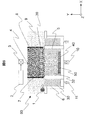
- the laser powder additive manufacturing apparatus 60 used in the present invention includes a roller 1 or a blade that supplies a powder resin 30 for supply to a modeling area, a laser light source 2 that is used to sinter or melt an installed resin powder 31 to perform lamination bonding, A galvanometer mirror 3 for moving the laser beam 4 at a high speed in the modeling area 8, a modeling container 5 in the modeling area 8, a reflector 7, and a storage container 6 for storing the powder material disposed on both sides of the modeling container 5, It is comprised from the heater (not shown) for hold
- the area temperature 9 of the container 6 for storing the powder material (powder resin) is preferably set to be equal to or lower than the temperature in the modeling area 8.
- Laminated modeling is a method in which a molded product 50 is produced three-dimensionally by spreading powder with a roller 1 or a blade, sintering or melting the resin powder 31 placed with a laser beam 4, and repeating them. After modeling, the modeled product 50 is in a state of being buried in the resin powder 32. After being taken out from the resin powder 32, the modeled product 50 is peeled from the modeled product 50 by blasting or the like.
- the modeling area 8 is preferably purged with nitrogen, argon or the like to reduce the oxygen concentration in order to suppress powder deterioration. Further, the laser light source 2 needs to be changed according to the absorption characteristics of the resin powder.
- a CO 2 laser (wavelength 10.6 ⁇ m) is generally used.
- the resin powder color includes a material that absorbs infrared light such as black, a fiber laser, a YAG laser, and a semiconductor laser (wavelength 800-1100 nm) may be used in addition to the CO 2 laser.
- the intensity distribution of the laser beam 4 is normally Gaussian, but it can be made higher definition if it is a top hat shape.
- the size of the resin powder to be used is preferably about ⁇ 10-100 ⁇ m.
- a 3D CAD model is often used for designing the object in advance in the laser powder additive manufacturing apparatus 60.
- a work procedure to be performed in each process such as each process such as an irradiation order of laser irradiation is set for each layer.
- This setting may be performed by a computer (not shown) used for design, a computer connected via a separate network or the like, and may take any form.
- the setting may be performed by the laser powder additive manufacturing apparatus 60.
- This 3D CAD model or information on the work procedure set from the 3D CAD model is stored in the storage unit of the laser powder additive manufacturing apparatus 60, and additive manufacturing is performed using the stored information.
- work procedure information, etc. means using communication from a network or the like from another computer, separate storage such as an optical disk such as a CD-ROM, MO, flash memory, etc. You may input the information of the said work procedure by transmission / reception etc. using an apparatus.
- a laser powder additive manufacturing method will be described as a representative example of the three-dimensional additive manufacturing.
- FIG. 1 is a plan view showing an embodiment of an additive manufacturing method and apparatus according to the present invention.
- powder resin powder or powder resin, but also simply called powder
- the powder is sintered to produce a thin layer, so that the sintering strength between thin layers, that is, the Z direction (vertical direction) is small.
- the powder is in close contact with the sintered portion only by its own weight before sintering with the laser beam 4, and voids between the layers are easily generated.
- the modeling area 8 during modeling is heated to 5 to 15 ° C. from the melting point of the resin material by heating with a heater or the like installed at a modeling location.
- the temperature is often set to a low temperature. This is called a process window method.
- the resin powder 31 is sufficiently wetted to the sintered part 33, it is necessary to develop a high strength, but the wettability is reduced by the bleed effect of the sintered part 33, and the strength between the thin layers is greatly reduced. And a significant increase in voids may occur.
- the present inventors have partially melted the surface by subjecting the sintered portion 33 before the resin powder 31 to installation to a surface modification treatment (hereinafter also simply referred to as “modification treatment”). It was found that the resin powder 31 sufficiently wets the sintered part 33 and greatly contributes to the improvement of strength between thin layers and the reduction of voids.
- these functional groups are generated on the surface of the sintered portion 33, the surface energy itself is greatly improved. Therefore, the surface energy of the sintered portion 33 can be increased with respect to the surface energy of the resin powder 31 to be joined, and the wettability is increased. The effect is improved.
- the portion subjected to the modification treatment generates or increases not only the surface but also oxygen functional groups in the treated region.
- a dry treatment that does not scatter the resin powder for example, an atmospheric pressure plasma treatment or a UV treatment (including UV ozone treatment) may be used to operate the resin powder 31.
- the amorphous resin is softened from the glass transition temperature, but the viscosity is not drastically lowered, and as a result, the sintered portion 33 is not wetted.
- the surface modification treatment of the present invention to the sintered portion 33, the adhesion between the sintered portion 33 and the powder irradiated with the laser is greatly improved, so that an amorphous resin can be used.
- the temperature of the modeling area 8 is often up to 200 ° C. from the viewpoint of the equipment cost, and there has been a serious limitation in the crystalline resin. Furthermore, even if the device window is allowed to increase and the process window method is adopted for the high melting point resin, the resin powders 31 and 32 are exposed to a high temperature of 200 ° C. or higher for a long time, so that the powders are partially adhered to each other. Since it becomes easy to become a cake lump (cake) and deterioration easily occurs, a significant deterioration in the recycling rate of the resin powders 31 and 32 becomes a problem.
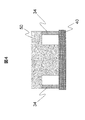
- the support substrate 40 when using a high melting point resin, it is preferable to use the support substrate 40 in order to keep the temperature of the modeling area 8 below the recrystallization temperature and suppress warping.
- the resin subjected to the dry treatment has a very small effect at a high temperature because the generation and increase of the functional group is accelerated when left at a high temperature. Therefore, the effect of the surface modification treatment is further improved by setting the modeling temperature as low as possible (for example, 100 ° C. or lower).
- the configuration shown in FIG. 2 is an effective method even for a resin having a low melting point and using the process window method.
- the above-mentioned quality refers to interlaminar strength and void reduction.
- the process window method since the process window method is not used, it is robust to temperature control and is effective in ensuring the quality of the large shaped product 50. Further, depending on the application target of the modeled product 50, the quality may be the same level as the process window method, and priority may be given to shortening the modeling time.
- the surface modification processing unit 20 is not built in the laser powder additive manufacturing apparatus 60, and the modeling substrate 8 is set to a relatively low temperature below the recrystallization degree, and the support substrate is subjected to surface treatment in advance. You may employ
- the overhang shape may not be applicable.
- the support 34 is preferably made of the same resin material as that of the modeled product 50 and produced with laser energy different from the formation of the modeled product 50.
- voids having a large amount and a large size are formed in the resin of the support 34.
- the void is not greatly affected by the shear stress generated during the warp and greatly depends on the impact strength. Therefore, if the impact stress is applied at the time of peeling, the void in the material of the support 34 itself. It becomes easy to destroy.
- the material of the support 34 can be easily broken as in the case where the energy is further increased.
- the material of the support substrate 40 is desirably a resin material having a rigidity and melting point higher than that of the resin material used for modeling or a metal having a relatively low thermal conductivity.
- the peeling of the support substrate 40 and the modeled product 50 can be caused to be interface failure by controlling the conditions of the surface modification treatment. Is greatly improved.
- WBL W eak B oundary L ayer
- the part or WBL joined by some surface treatment is particularly weak against moisture and solvent, so that after modeling, the molded product and the support substrate 40 can be left in a high humidity atmosphere or immersed in a solvent or moisture. Their peeling is also easy. Furthermore, since the mode that breaks at the interface greatly depends on the impact strength as compared with the shear stress generated during warping, the interface breakage is facilitated by applying the impact stress at the time of peeling.
- the shaped product 50 and the support substrate 40 be joined to the peripheral portion of the shaped product 50. Also, by providing the support substrate 40 with the holes 41, it becomes possible to directly apply a load to the molded product, and particularly the close contact portion can be subjected to a peeling stress that easily causes interfacial breakage, so that the peelability is further improved. To do.
- a metal having a relatively low thermal conductivity for example, 30 W / mK
- it is also effective to improve the peelability by applying a peeling stress after the support substrate 40 is heated to a high temperature.
- the surface roughness of the support plate material is desirably a relatively smooth state, that is, a surface roughness of Ra 0.5 ⁇ m or less, from the viewpoint of causing the interface breakage between the support substrate 40 and the shaped product 50.
- the mold should be mirror-finished, and if it is made of a material such as metal or ceramics, it should be made of abrasive paper with relatively small roughness. It is good to polish.
- the support substrate 40 having a higher thermal conductivity than that of the resin when a metal or the like is used for the support substrate 40 having a higher thermal conductivity than that of the resin, if the heater is provided at the bottom of the support substrate 40, the support substrate 40 and the resin powder 31 can be irradiated with a lower energy laser. Can be joined. Furthermore, in the case of layered modeling of a modeled object (modeling model) with a small thickness, even when the modeling area 8 is small, that is, in a state where the environmental temperature is low, it is possible to suppress warping of the modeled product 50 during modeling. .
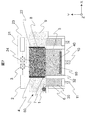
- the surface modification processing unit 20 can cope with it by retracting in the Z direction. Further, when the surface modification processing unit 20 is operated only in the plane direction due to the configuration or the price of the laser powder additive manufacturing apparatus 60, the roller 1 and the surface modification processing unit 20 are crossed as shown in FIG. It is good to arrange and drive. In that case, for example, when the roller 1 operates in the X direction, the surface modification processing unit 20 operates in the Y direction. Of course, the reverse is also possible.
- the intersecting angle need not be exactly 90 degrees and may be changed as appropriate.
- the surface modification processing unit 20 has been described as being mechanically operated in the same manner as a roller.
- a UV laser wavelength of 300 nm or less, eg, an excimer laser
- an ultrashort pulse with a pulse width of You may use below ps (for example, titanium sapphire laser).
- a galvano mirror 24 may be installed and operated.
- the support 43 made of the same material may be provided on the support substrate 40 by a process as shown in FIG.
- the support 43 is manufactured by modeling, and the material may be the same as that of the modeled product 50.
- the support 43 has a relationship with the support substrate 40 employed in the overhang structure. It is desirable.
- the support 43 is directly destroyed in the process of peeling the support 43 and the molded product 50.
- the shaped article 50 and the support substrate 40 are not in close contact with each other, the laser energy used for joining the support 43 and the support substrate 40 can be increased.
- the support substrate 40 can use a metal having higher thermal conductivity (for example, 250 W / mK). When such a material is used, the releasability when the support substrate 40 is heated becomes easy. Further, it becomes possible to use the support substrate 40 having a weak oxide film strength on the surface such as Al, and the interface separation between the support substrate 40 and the support 43 becomes easier.
- a metal having higher thermal conductivity for example, 250 W / mK.
- FIG. 9 it is good to form the through-holes 41 and 44 in the support board
- the bonding area between the support 43 and the modeled product 50 be smaller than the bonding area between the support substrate 40 and the support 43.
- the rigidity of the support substrate 40 is desirably higher than the rigidity of the support 43.
- the surface roughness of the support substrate 40 be about 0.5 ⁇ m, but in the case of the present invention, the surface roughness may be increased to 7.0 ⁇ m.
- the surface roughness may be larger than 7.0 ⁇ m, only a part of the resin enters, and the strength of the support 43 and the support substrate 40 becomes weak.
- the support substrate 40 is made of resin and manufactured by injection molding, the mold may be roughened and the surface of the support substrate 40 may be formed into a textured shape.
- the support substrate 40 When the support substrate 40 is made of metal, it may be sandblasted or processed with abrasive paper having a relatively large roughness.
- the support 34 may be used in the case of an overhang shape. Further, the number of support substrates 40 and the number of supports 34 are not limited to one and may be plural depending on circumstances.
- each of the embodiments described so far can be carried out independently, but in particular, by using a surface modification treatment in combination, as shown in FIG.
- the product 50 can also be manufactured.
- the methods described so far may be combined, but it is desirable that the linear expansion coefficient between the powdered resins is as high as possible.
- a 3D CAD model is used.
- the structure of the support substrate 40 and the support 43 is software using software built into the model for modeling.
- the modeled model is modeled in consideration of the part to be peeled off, and the quality of the modeled object is further improved.
- the laser irradiation conditions vary greatly depending on the physical properties of the materials of the support substrate 40 and the support 43, the laser irradiation conditions and the material information (materials, bondability, materials related to sintering, materials related to design, etc.) It is even better to include in the software information that includes information related to modeling, not only information alone but also information configured using a plurality of information and related to modeling). The laser irradiation conditions become more suitable, and the quality of the shaped article is increased.
- the powder resin material which can employ the present invention is polyamide 12 (PA12), polyamide 11 (PA11), polyethylene (PE), polypropylene (PP), polyoxy as a crystalline resin material having a low melting point of 200 ° C. or less.
- Methylene (POM) and the like are targeted.
- polybutylene terephthalate PBT
- polyphenylene sulfide PPS
- polyamide 6 PA6
- PA66 polyamide 6T
- PA9T PA9T
- PEEK Polyether ether ketone
- LCP liquid crystal polymer
- PET polyethylene terephthalate
- PTT polytrimethylene terephthalate
- PEN polyethylene naphthalate
- PTFE polytetrafluoroethylene
- Non-crystalline resin materials include polystyrene (PS), acrylonitrile styrene (AS), acrylonitrile butadiene styrene copolymer (ABS), polymethyl methacrylate (PMMA), cycloolefin polymer (COP), and cycloolefin copolymer.
- PS polystyrene
- AS acrylonitrile styrene
- ABS acrylonitrile butadiene styrene copolymer
- PMMA polymethyl methacrylate
- COP cycloolefin polymer
- COC cycloolefin copolymer
- PVC polyvinyl chloride
- PC polycarbonate
- mPPE polycarbonate
- PEI polyphenylene ether
- PAR polyetherimide
- PAR polyarylate
- PES polysulfone
- an alloy material containing 1-30% of the non-crystalline resin in the crystalline resin is also targeted.
- the crystalline resin material may be compounded by containing 1-30% of an inorganic material such as glass, alumina, carbon material or a part of metal powder.
- an inorganic material coated with the resin material may be used.
- a main material you may apply not only to a thermoplastic resin but to thermosetting resins, such as an epoxy type and an acrylic type.
- the support substrate 40 in addition to the above crystalline resin material, SUS and Al, as well as metals (including die cast) and ceramics having a thermal conductivity of 250 W / mK or less may be used.
- the laser powder additive manufacturing method has been described as a target until now, but the present invention includes an additive manufacturing method in which molten resin is discharged from a nozzle and stacked, and an additive manufacturing method in which resin is discharged by inkjet and stacked. It is also effective for other methods and apparatuses.
Abstract
Description
その理由として、レーザ粉末積層造形方法は、射出成形でも使用できる樹脂が使用可能な方法であるため、造形品の強度、信頼性、寸法安定性がその他の造形方法に比べて、高いことが挙げられる。 Three-dimensional additive manufacturing is a method that does not use a mold, and therefore has an advantage that it can be prototyped in a short period of time. In recent years, it has been increasingly used for prototypes for function confirmation. In addition to application to trial production, there is an increasing need for application to direct production of a small variety of products. Against this background, in recent years, laser powder additive manufacturing methods (in this application, laser powder additive manufacturing methods are also referred to as laser additive manufacturing methods, devices corresponding to this method are also referred to as laser additive manufacturing devices, and three-dimensional additive manufacturing methods are also included. The apparatus or method is also called “three-dimensional powder additive manufacturing apparatus or method”.
The reason for this is that the laser powder additive manufacturing method is a method in which a resin that can be used in injection molding can be used, so that the strength, reliability, and dimensional stability of the molded product are higher than those of other modeling methods. It is done.
本願は上記課題を解決する手段を複数含んでいるが、その一例を挙げるならば、粉末材料を薄層として設置する工程と、設置された粉末材料にレーザを照射することで、焼結もしくは溶融させるレーザ照射工程と、を有する積層造形物を製作するレーザ粉末造形方法であって、設置する工程の前あるいは後またはレーザ照射工程の前あるいは後に、レーザを照射する領域の酸素官能基を生成させるあるいは増加させる表面改質処理を行う工程と、を有することを特徴とする。 In order to solve the above problems, for example, the configuration described in the claims is adopted.
The present application includes a plurality of means for solving the above-mentioned problems. To give an example, a step of installing the powder material as a thin layer and irradiating the installed powder material with a laser sinter or melt. A laser powder shaping method for producing a layered object having a laser irradiation step, wherein an oxygen functional group in a region to be irradiated with laser is generated before or after the installation step or before or after the laser irradiation step. Or a step of increasing the surface modification treatment.
なお、造形エリア8に供給する以前の粉末30自体にも表面改質処理を施しておくと更に良い。 Therefore, in the case of using a small-sized resin powder or nonpolar resin, if the surface modification treatment is performed, the installation property of the powder is improved, so that molding defects can be significantly suppressed.
In addition, it is better if the
ボイドは、反りの際に発生するせん断応力に対しては、大きな影響を受けず、衝撃強度には大きく依存するため、剥離する際に、衝撃的な応力を加えると、サポート34の材料自体で破壊することが容易となる。 In particular, when the laser energy is further increased as compared with the case where the shaped
The void is not greatly affected by the shear stress generated during the warp and greatly depends on the impact strength. Therefore, if the impact stress is applied at the time of peeling, the void in the material of the
特に、造形樹脂と異なる樹脂材料や熱伝導率の比較的低い金属を用いれば、表面改質処理の条件をコントロールすることで、サポート基板40と造形品50の剥離を界面破壊とでき、作業性が大幅に向上する。 In the method using the
In particular, if a resin material different from the modeling resin or a metal having a relatively low thermal conductivity is used, the peeling of the
さらに、造形物(造形モデル)の厚みが薄いものを積層造形する場合は、造形エリア8を小さくした状態つまり環境温度が低い状態でもその効果で造形時の造形品50の反りも抑制可能となる。 For example, when a metal or the like is used for the
Furthermore, in the case of layered modeling of a modeled object (modeling model) with a small thickness, even when the
その場合、例えば、ローラ1がX方向に動作する場合は、表面改質処理ユニット20はY方向に動作することとなる。もちろん逆としても良い。上記交差する角度は正確に90度である必要はなく適宜変更してもよい。 In that case, when the
In that case, for example, when the
なお、サポート基板40を樹脂とし、射出成形で作製した場合は、金型を荒らし、サポート基板40の表面をシボ形状としても良い。サポート基板40を金属とした場合は、サンドブラストの実施や比較的粗さの大きい研磨紙で加工などをしても良い。
なお、本発明の上記実施形態においても、オーバハング形状の場合は、サポート34を使用しても良い。また、サポート基板40の数やサポート34の数は1つのみならず場合によっては、複数あっても良い。 Similarly to the above, it is desirable that the surface roughness of the
In addition, when the
In the above embodiment of the present invention, the
Claims (16)
- 粉末材料を薄層として設置する工程と、設置された粉末材料にレーザを照射することで、焼結もしくは溶融させるレーザ照射工程と、を有する積層造形物を製作するレーザ粉末積層造形方法であって、
前記設置する工程の前あるいは後または前記レーザ照射工程の前あるいは後に、レーザを照射する領域の酸素官能基を生成させるあるいは増加させる表面改質処理を行う工程と、
を有することを特徴とするレーザ粉末積層造形方法。 A laser powder additive manufacturing method for manufacturing a layered object having a step of installing a powder material as a thin layer, and a laser irradiation step of sintering or melting the irradiated powder material by irradiating a laser. ,
Before or after the step of installing or before or after the laser irradiation step, performing a surface modification process for generating or increasing oxygen functional groups in the region irradiated with laser; and
A laser powder additive manufacturing method comprising: - 請求項1に記載のレーザ粉末積層造形方法において、
前記表面改質処理は、プラズマ処理またはUVレーザ処理または短パルスレーザ処理またはUV処理またはUVオゾン処理またはコロナ処理のいずれかのドライ処理であることを特徴とするレーザ粉末積層造形方法。 In the laser powder additive manufacturing method according to claim 1,
The laser powder additive manufacturing method characterized in that the surface modification treatment is a dry treatment of plasma treatment, UV laser treatment, short pulse laser treatment, UV treatment, UV ozone treatment, or corona treatment. - 請求項1に記載のレーザ粉末積層造形方法において、
前記レーザ照射工程において、前記表面改質処理を行った接合材料より、前記粉末材料のうちレーザを照射する部分の表面エネルギーを小さくした状態で、レーザを照射すること
を特徴とするレーザ粉末積層造形方法。 In the laser powder additive manufacturing method according to claim 1,
In the laser irradiation step, the laser powder additive manufacturing is characterized in that the laser irradiation is performed in a state where the surface energy of the portion of the powder material irradiated with the laser is smaller than the bonding material subjected to the surface modification treatment. Method. - 請求項1に記載のレーザ粉末積層造形方法において、
前記粉末材料は前記粉末材料と異なる材料で構成されるサポート部材に設置されることを特徴とするレーザ粉末積層造形方法。 In the laser powder additive manufacturing method according to claim 1,
The laser powder additive manufacturing method, wherein the powder material is placed on a support member made of a material different from the powder material. - 請求項1に記載のレーザ粉末積層造形方法において、
前記粉末材料は前記粉末材料と同一の材料で構成されるサポート部材に設置されることを特徴とするレーザ粉末積層造形方法。 In the laser powder additive manufacturing method according to claim 1,
The laser powder additive manufacturing method, wherein the powder material is placed on a support member made of the same material as the powder material. - 請求項1乃至5のいずれか一項に記載のレーザ粉末積層造形方法において、
前記粉末材料は、無極性樹脂としたことを特徴とするレーザ粉末積層造形方法。 In the laser powder additive manufacturing method according to any one of claims 1 to 5,
The laser powder additive manufacturing method, wherein the powder material is a nonpolar resin. - 請求項4または5のいずれか一項に記載のレーザ粉末積層造形方法において、
前記粉末材料にレーザを照射する造形エリアの温度を前記粉末樹脂の再結晶化温度以下とし、前記サポート部材は前記積層造形品を支持すること
を特徴とするレーザ粉末積層造形方法。 In the laser powder additive manufacturing method according to any one of claims 4 and 5,
The laser powder additive manufacturing method characterized in that the temperature of the modeling area for irradiating the powder material with laser is set to be equal to or lower than the recrystallization temperature of the powder resin, and the support member supports the additive manufacturing product. - 請求項4または5のいずれか一項に記載のレーザ粉末積層造形方法において、
前記粉末材料にレーザを照射する造形エリアの温度を前記粉末樹脂のガラス転移温度以下とし、前記サポート部材は前記積層造形品を支持すること
を特徴とするレーザ粉末積層造形方法。 In the laser powder additive manufacturing method according to any one of claims 4 and 5,
The laser powder additive manufacturing method characterized in that the temperature of the modeling area for irradiating the powder material with laser is set to be equal to or lower than the glass transition temperature of the powder resin, and the support member supports the additive manufacturing product. - 請求項4または5に記載のレーザ粉末積層造形方法において、
前記サポート部材は、前記粉末樹脂より剛性が高い材料であること
を特徴とするレーザ粉末積層造形方法。 In the laser powder additive manufacturing method according to claim 4 or 5,
The laser powder additive manufacturing method, wherein the support member is a material having higher rigidity than the powder resin. - 請求項4または5に記載のレーザ粉末積層造形方法において、
前記サポート部材の表面粗さをRa0.5μm以下としたことを特徴とするレーザ粉末積層造形方法。 In the laser powder additive manufacturing method according to claim 4 or 5,
A laser powder additive manufacturing method, wherein the support member has a surface roughness Ra of 0.5 μm or less. - 請求項4または5に記載のレーザ粉末積層造形方法において、
前記サポート部材を前記粉末材料にレーザを照射する造形エリアの温度より高くなるように加熱すること
を特徴とするレーザ粉末積層造形方法。 In the laser powder additive manufacturing method according to claim 4 or 5,
The laser powder additive manufacturing method, wherein the support member is heated so as to be higher than a temperature of a modeling area in which the powder material is irradiated with laser. - 請求項4または5に記載のレーザ粉末積層造形方法において、
前記サポート部材とは異なるサポート部材を粉末造形で形成すること
を特徴とするレーザ粉末積層造形方法。 In the laser powder additive manufacturing method according to claim 4 or 5,
A laser powder additive manufacturing method, wherein a support member different from the support member is formed by powder modeling. - 請求項4または5に記載のレーザ粉末積層造形方法において、
前記サポート部材には、前記サポート部材を貫通する孔が設けられていること
を特徴とするレーザ粉末積層造形方法。 In the laser powder additive manufacturing method according to claim 4 or 5,
The laser powder additive manufacturing method, wherein the support member is provided with a hole penetrating the support member. - 請求項1乃至5のいずれか一項に記載のレーザ粉末積層造形方法において、
少なくとも一度前記表面改質工程を行った後に、前記粉末材料と異なる第二の粉末材料を用いて前記設置する工程を行うこと
を特徴とするレーザ粉末積層造形方法。 In the laser powder additive manufacturing method according to any one of claims 1 to 5,
A laser powder additive manufacturing method characterized by performing the installation step using a second powder material different from the powder material after performing the surface modification step at least once. - 粉末材料の薄層をレーザにより焼結もしくは溶融し、接合積層を繰り返して3次元造形物を作製するレーザ粉末積層造形装置であって、
前記粉末材料の薄層を供給部と、粉末を焼結・溶融させるレーザ照射部と、レーザを照射する領域に酸素官能基を発生もしくは増加させる表面改質部と、前記粉末材料にレーザを照射する造形エリアを囲む造形容器部と、前記造形容器部内に前記造形エリアに供給する粉末材料を保管する容器と、前記造形エリア及び前記保管容器を略鉛直方向に稼動するピストンと、前記造形エリア及び造形容器を加熱するヒータと、
を備えたことを特徴とするレーザ粉末積層造形装置。 A laser powder additive manufacturing apparatus that sinters or melts a thin layer of powder material with a laser and repeats joint lamination to produce a three-dimensional object,
Supplying a thin layer of the powder material, a laser irradiation unit for sintering and melting the powder, a surface modification unit for generating or increasing oxygen functional groups in the laser irradiation region, and irradiating the powder material with a laser A modeling container that surrounds the modeling area, a container that stores the powder material supplied to the modeling area in the modeling container, a piston that operates the modeling area and the storage container in a substantially vertical direction, the modeling area, and A heater for heating the modeling container;
A laser powder additive manufacturing apparatus comprising: - 粉末材料を薄層として設置する工程と、設置された粉末材料を焼結もしくは溶融させる粉末材料処理工程と、を有する積層造形物を製作する3次元積層造形装置であって、
前記設置する工程の前あるいは後、または前記粉末材料処理工程の前あるいは後に、焼結もしくは溶融させる前記設置された粉末材料の領域に対して、酸素官能基を生成させるあるいは増加させる表面改質処理を行う工程と、
を有することを特徴とする3次元積層造形装置。 A three-dimensional additive manufacturing apparatus that manufactures an additive manufacturing object having a step of installing a powder material as a thin layer and a powder material processing step of sintering or melting the installed powder material,
Surface modification treatment for generating or increasing oxygen functional groups in the region of the installed powder material to be sintered or melted before or after the installation step or before or after the powder material treatment step A process of performing
A three-dimensional additive manufacturing apparatus characterized by comprising:
Priority Applications (2)
| Application Number | Priority Date | Filing Date | Title |
|---|---|---|---|
| JP2016509891A JP6190038B2 (en) | 2014-03-28 | 2014-10-22 | Laser powder additive manufacturing apparatus, laser powder additive manufacturing method, and three-dimensional additive manufacturing apparatus |
| US15/110,517 US20160332370A1 (en) | 2014-03-28 | 2014-10-22 | Laser Powder Lamination Shaping Device, Laser Powder Lamination Shaping Method, and 3D Lamination Shaping Device |
Applications Claiming Priority (2)
| Application Number | Priority Date | Filing Date | Title |
|---|---|---|---|
| JP2014067462 | 2014-03-28 | ||
| JP2014-067462 | 2014-03-28 |
Publications (1)
| Publication Number | Publication Date |
|---|---|
| WO2015145844A1 true WO2015145844A1 (en) | 2015-10-01 |
Family
ID=54194416
Family Applications (1)
| Application Number | Title | Priority Date | Filing Date |
|---|---|---|---|
| PCT/JP2014/078014 WO2015145844A1 (en) | 2014-03-28 | 2014-10-22 | Laser powder lamination shaping device, laser powder lamination shaping method, and 3d lamination shaping device |
Country Status (3)
| Country | Link |
|---|---|
| US (1) | US20160332370A1 (en) |
| JP (1) | JP6190038B2 (en) |
| WO (1) | WO2015145844A1 (en) |
Cited By (17)
| Publication number | Priority date | Publication date | Assignee | Title |
|---|---|---|---|---|
| CN105522155A (en) * | 2016-03-03 | 2016-04-27 | 中研智能装备有限公司 | Plasma 3D fast forming and remanufacturing method and equipment of train wheels |
| CN105710371A (en) * | 2016-03-03 | 2016-06-29 | 中研智能装备有限公司 | Plasma 3D printing remanufacturing equipment and method for train wheel |
| CN106180710A (en) * | 2016-07-14 | 2016-12-07 | 武汉鑫双易科技开发有限公司 | 3D metal based on plasma arc cladding increases material and manufactures device and method |
| JP2017075364A (en) * | 2015-10-15 | 2017-04-20 | セイコーエプソン株式会社 | Method for manufacturing three-dimensional molded object and apparatus for manufacturing three-dimensional molded object |
| US20170209929A1 (en) * | 2016-01-22 | 2017-07-27 | Seiko Epson Corporation | Three-dimensional shaped article production method |
| WO2017126484A1 (en) * | 2016-01-20 | 2017-07-27 | 東レ株式会社 | Polyarylene sulfide resin granular article and method for producing same |
| WO2017221913A1 (en) * | 2016-06-22 | 2017-12-28 | パナソニックIpマネジメント株式会社 | Production method for three-dimensional molded product |
| WO2017221912A1 (en) * | 2016-06-22 | 2017-12-28 | パナソニックIpマネジメント株式会社 | Method for producing three-dimensional molded product |
| JP2018196953A (en) * | 2017-05-24 | 2018-12-13 | 株式会社リコー | Support material for three-dimensional fabrication, set of model material for three-dimensional fabrication and support material for three-dimensional fabrication, method for manufacturing three-dimensional object, and apparatus for three-dimensional fabrication |
| JP2019510094A (en) * | 2016-01-21 | 2019-04-11 | スリーエム イノベイティブ プロパティズ カンパニー | Fluoropolymer lamination process |
| JP2019526704A (en) * | 2016-08-10 | 2019-09-19 | レニショウ パブリック リミテッド カンパニーRenishaw Public Limited Company | Method and system including additive manufacturing, and additive manufactured articles |
| WO2019189347A1 (en) | 2018-03-30 | 2019-10-03 | 株式会社アスペクト | Powder bed fused molded object and method for producing same |
| JP2020518485A (en) * | 2017-04-28 | 2020-06-25 | ダイバージェント テクノロジーズ, インコーポレイテッドDivergent Technologies, Inc. | Support structure in additive manufacturing |
| WO2020188648A1 (en) * | 2019-03-15 | 2020-09-24 | 株式会社ニコン | Modeling method, modeling system, and modeling base |
| US11154933B2 (en) | 2015-12-17 | 2021-10-26 | Seiko Epson Corporation | Three-dimensional shaped article production method, three-dimensional shaped article production apparatus, and three-dimensional shaped article |
| US11267052B2 (en) | 2014-11-21 | 2022-03-08 | Renishaw Plc | Additive manufacturing apparatus and methods |
| US11925981B2 (en) * | 2020-06-29 | 2024-03-12 | Arcam Ab | Method, apparatus and control unit for selectively sintering a powder layer in additive manufacturing processes to achieve a future, desired heat conductivity |
Families Citing this family (13)
| Publication number | Priority date | Publication date | Assignee | Title |
|---|---|---|---|---|
| US10029421B2 (en) * | 2014-09-18 | 2018-07-24 | 3Dm Digital Manufacturing Ltd | Device and a method for 3D printing and manufacturing of materials using quantum cascade lasers |
| JP6825333B2 (en) * | 2016-11-28 | 2021-02-03 | 株式会社リコー | Manufacturing method of three-dimensional model and manufacturing equipment of three-dimensional model |
| AT15637U1 (en) * | 2017-01-17 | 2018-03-15 | Univ Innsbruck | Process for additive manufacturing |
| JP6961972B2 (en) * | 2017-03-24 | 2021-11-05 | 富士フイルムビジネスイノベーション株式会社 | Three-dimensional shape molding equipment, information processing equipment and programs |
| CN111344428B (en) * | 2017-11-16 | 2022-08-16 | 睦月电机株式会社 | Metal member, method for producing metal member, metal-resin bonded body, and method for producing metal-resin bonded body |
| CN111356738B (en) * | 2017-11-30 | 2022-07-26 | 惠普发展公司,有限责任合伙企业 | Anti-coalescing agent for three-dimensional printing |
| JP7067134B2 (en) * | 2018-03-07 | 2022-05-16 | 株式会社ジェイテクト | Modeling method of laminated modeling device and laminated modeling device |
| US11577458B2 (en) * | 2018-06-29 | 2023-02-14 | 3M Innovative Properties Company | Additive layer manufacturing method and articles |
| RU2705821C1 (en) * | 2018-08-10 | 2019-11-12 | Федеральное государственное бюджетное образовательное учреждение высшего образования Балтийский государственный технический университет "ВОЕНМЕХ" им. Д.Ф. Устинова (БГТУ "ВОЕНМЕХ") | Method for laser layer-by-layer synthesis of three-dimensional article with internal channels |
| US10926460B2 (en) * | 2018-09-28 | 2021-02-23 | The Boeing Company | Methods and apparatus for additively manufacturing a structure with in-situ reinforcement |
| US10926461B2 (en) * | 2018-09-28 | 2021-02-23 | The Boeing Company | Methods and apparatus for additively manufacturing a structure with in-situ reinforcement |
| US10926325B2 (en) * | 2018-09-28 | 2021-02-23 | The Boeing Company | Methods and apparatus for additively manufacturing a structure with in-situ reinforcement |
| US11648729B2 (en) * | 2019-06-03 | 2023-05-16 | The Boeing Company | Additive manufacturing powder particle, method for treating the additive manufacturing powder particle, and method for additive manufacturing |
Citations (6)
| Publication number | Priority date | Publication date | Assignee | Title |
|---|---|---|---|---|
| JPH09506553A (en) * | 1995-03-20 | 1997-06-30 | イーオーエス ゲゼルシャフト ミット ベシュレンクテル ハフツング イレクトロ オプティカル システムズ | Device and method for manufacturing three-dimensional object by laser sintering |
| JP2004074800A (en) * | 2002-08-09 | 2004-03-11 | Eos Gmbh Electro Optical Systems | Method and device for manufacturing three-dimensional object |
| JP2006045584A (en) * | 2004-07-30 | 2006-02-16 | Media Plus Inc | Layering shaping method |
| JP2010527810A (en) * | 2007-05-25 | 2010-08-19 | イーオーエス ゲゼルシャフト ミット ベシュレンクテル ハフツング イレクトロ オプティカル システムズ | Layered manufacturing method for three-dimensional objects |
| JP2011173420A (en) * | 2010-02-23 | 2011-09-08 | Eos Gmbh Electro Optical Systems | Method and apparatus for manufacturing three dimensional object suitable for microtechnology |
| JP2012096428A (en) * | 2010-11-01 | 2012-05-24 | Keyence Corp | Three-dimensional shaping apparatus and three-dimensional shaping method |
-
2014
- 2014-10-22 WO PCT/JP2014/078014 patent/WO2015145844A1/en active Application Filing
- 2014-10-22 US US15/110,517 patent/US20160332370A1/en not_active Abandoned
- 2014-10-22 JP JP2016509891A patent/JP6190038B2/en not_active Expired - Fee Related
Patent Citations (6)
| Publication number | Priority date | Publication date | Assignee | Title |
|---|---|---|---|---|
| JPH09506553A (en) * | 1995-03-20 | 1997-06-30 | イーオーエス ゲゼルシャフト ミット ベシュレンクテル ハフツング イレクトロ オプティカル システムズ | Device and method for manufacturing three-dimensional object by laser sintering |
| JP2004074800A (en) * | 2002-08-09 | 2004-03-11 | Eos Gmbh Electro Optical Systems | Method and device for manufacturing three-dimensional object |
| JP2006045584A (en) * | 2004-07-30 | 2006-02-16 | Media Plus Inc | Layering shaping method |
| JP2010527810A (en) * | 2007-05-25 | 2010-08-19 | イーオーエス ゲゼルシャフト ミット ベシュレンクテル ハフツング イレクトロ オプティカル システムズ | Layered manufacturing method for three-dimensional objects |
| JP2011173420A (en) * | 2010-02-23 | 2011-09-08 | Eos Gmbh Electro Optical Systems | Method and apparatus for manufacturing three dimensional object suitable for microtechnology |
| JP2012096428A (en) * | 2010-11-01 | 2012-05-24 | Keyence Corp | Three-dimensional shaping apparatus and three-dimensional shaping method |
Cited By (25)
| Publication number | Priority date | Publication date | Assignee | Title |
|---|---|---|---|---|
| US11267052B2 (en) | 2014-11-21 | 2022-03-08 | Renishaw Plc | Additive manufacturing apparatus and methods |
| JP2017075364A (en) * | 2015-10-15 | 2017-04-20 | セイコーエプソン株式会社 | Method for manufacturing three-dimensional molded object and apparatus for manufacturing three-dimensional molded object |
| US11154933B2 (en) | 2015-12-17 | 2021-10-26 | Seiko Epson Corporation | Three-dimensional shaped article production method, three-dimensional shaped article production apparatus, and three-dimensional shaped article |
| JP6256818B2 (en) * | 2016-01-20 | 2018-01-10 | 東レ株式会社 | Polyarylene sulfide resin powder and method for producing the same |
| WO2017126484A1 (en) * | 2016-01-20 | 2017-07-27 | 東レ株式会社 | Polyarylene sulfide resin granular article and method for producing same |
| US11008426B2 (en) | 2016-01-20 | 2021-05-18 | Toray Industries, Inc. | Polyarylene sulfide resin particulate and method of producing same |
| JPWO2017126484A1 (en) * | 2016-01-20 | 2018-01-25 | 東レ株式会社 | Polyarylene sulfide resin powder and method for producing the same |
| JP2019510094A (en) * | 2016-01-21 | 2019-04-11 | スリーエム イノベイティブ プロパティズ カンパニー | Fluoropolymer lamination process |
| US20170209929A1 (en) * | 2016-01-22 | 2017-07-27 | Seiko Epson Corporation | Three-dimensional shaped article production method |
| CN106994515A (en) * | 2016-01-22 | 2017-08-01 | 精工爱普生株式会社 | The manufacture method of three-D moulding object |
| CN106994515B (en) * | 2016-01-22 | 2021-05-11 | 精工爱普生株式会社 | Method for manufacturing three-dimensional shaped object |
| US10814389B2 (en) * | 2016-01-22 | 2020-10-27 | Seiko Epson Corporation | Three-dimensional shaped article production method |
| CN105710371A (en) * | 2016-03-03 | 2016-06-29 | 中研智能装备有限公司 | Plasma 3D printing remanufacturing equipment and method for train wheel |
| CN105522155A (en) * | 2016-03-03 | 2016-04-27 | 中研智能装备有限公司 | Plasma 3D fast forming and remanufacturing method and equipment of train wheels |
| JPWO2017221912A1 (en) * | 2016-06-22 | 2019-03-14 | パナソニックIpマネジメント株式会社 | Manufacturing method of three-dimensional shaped object |
| JPWO2017221913A1 (en) * | 2016-06-22 | 2019-03-22 | パナソニックIpマネジメント株式会社 | Method of manufacturing three-dimensional shaped object |
| WO2017221912A1 (en) * | 2016-06-22 | 2017-12-28 | パナソニックIpマネジメント株式会社 | Method for producing three-dimensional molded product |
| WO2017221913A1 (en) * | 2016-06-22 | 2017-12-28 | パナソニックIpマネジメント株式会社 | Production method for three-dimensional molded product |
| CN106180710A (en) * | 2016-07-14 | 2016-12-07 | 武汉鑫双易科技开发有限公司 | 3D metal based on plasma arc cladding increases material and manufactures device and method |
| JP2019526704A (en) * | 2016-08-10 | 2019-09-19 | レニショウ パブリック リミテッド カンパニーRenishaw Public Limited Company | Method and system including additive manufacturing, and additive manufactured articles |
| JP2020518485A (en) * | 2017-04-28 | 2020-06-25 | ダイバージェント テクノロジーズ, インコーポレイテッドDivergent Technologies, Inc. | Support structure in additive manufacturing |
| JP2018196953A (en) * | 2017-05-24 | 2018-12-13 | 株式会社リコー | Support material for three-dimensional fabrication, set of model material for three-dimensional fabrication and support material for three-dimensional fabrication, method for manufacturing three-dimensional object, and apparatus for three-dimensional fabrication |
| WO2019189347A1 (en) | 2018-03-30 | 2019-10-03 | 株式会社アスペクト | Powder bed fused molded object and method for producing same |
| WO2020188648A1 (en) * | 2019-03-15 | 2020-09-24 | 株式会社ニコン | Modeling method, modeling system, and modeling base |
| US11925981B2 (en) * | 2020-06-29 | 2024-03-12 | Arcam Ab | Method, apparatus and control unit for selectively sintering a powder layer in additive manufacturing processes to achieve a future, desired heat conductivity |
Also Published As
| Publication number | Publication date |
|---|---|
| JP6190038B2 (en) | 2017-08-30 |
| US20160332370A1 (en) | 2016-11-17 |
| JPWO2015145844A1 (en) | 2017-04-13 |
Similar Documents
| Publication | Publication Date | Title |
|---|---|---|
| JP6190038B2 (en) | Laser powder additive manufacturing apparatus, laser powder additive manufacturing method, and three-dimensional additive manufacturing apparatus | |
| JP6178933B2 (en) | Mold based on hot melt lamination method for molding and replicating an object, method for its production and hot melt lamination type 3D printer | |
| JP6808816B2 (en) | Lamination of modeling material particles | |
| CN108349046A (en) | The method for manufacturing plastic-metal engagement by laser | |
| JP6655714B2 (en) | Resin molding and laser powder additive manufacturing device | |
| JP6384826B2 (en) | Three-dimensional additive manufacturing apparatus, three-dimensional additive manufacturing method, and three-dimensional additive manufacturing program | |
| JP2013022965A (en) | Apparatus and method for manufacturing three-dimensional object in layers, and mold | |
| JP6888259B2 (en) | Laminated modeling structure, laminated modeling method and laminated modeling equipment | |
| JP2013022964A (en) | Apparatus and method for manufacturing three-dimensional object in layers, polymer powder and mold | |
| JP2010121187A (en) | Three-dimensional shaped article and method for producing the same | |
| JP2015196268A (en) | Apparatus and method for production of laminated molding and liquid raw material | |
| JP2010196099A (en) | Apparatus and method of producing three-dimensional shaped article | |
| Mousa et al. | Additive manufacturing: a new industrial revolution-A review | |
| JP2018141224A (en) | Composition for producing three-dimensional molded article, method for producing three-dimensional molded article, and apparatus for producing three-dimensional molded article | |
| JP7137228B2 (en) | Resin molding method | |
| JP7137229B2 (en) | Resin molding method | |
| JP2004142427A (en) | Manufacturing process for three-dimensionally shaped product | |
| Niese et al. | Laser-based generation of conductive circuits on additive manufactured thermoplastic substrates | |
| KR102028599B1 (en) | Method for transfering functional material layer on three-dimensional print object | |
| US20220168968A1 (en) | Resin molding method | |
| TWI730455B (en) | Method for molding a ceramic material and molding apparatus thereof | |
| JP6604002B2 (en) | Additive manufacturing apparatus and additive manufacturing method | |
| KR100848707B1 (en) | mold for injection molding | |
| WO2022107307A1 (en) | Production method and production device for three-dimensionally fabricated object | |
| JP7137227B2 (en) | Preforming apparatus, preforming method, resin molding system, and resin molding method |
Legal Events
| Date | Code | Title | Description |
|---|---|---|---|
| 121 | Ep: the epo has been informed by wipo that ep was designated in this application |
Ref document number: 14887645 Country of ref document: EP Kind code of ref document: A1 |
|
| ENP | Entry into the national phase |
Ref document number: 2016509891 Country of ref document: JP Kind code of ref document: A |
|
| WWE | Wipo information: entry into national phase |
Ref document number: 15110517 Country of ref document: US |
|
| NENP | Non-entry into the national phase | ||
| 122 | Ep: pct application non-entry in european phase |
Ref document number: 14887645 Country of ref document: EP Kind code of ref document: A1 |