WO2015141806A1 - Palier à feuilles - Google Patents
Palier à feuilles Download PDFInfo
- Publication number
- WO2015141806A1 WO2015141806A1 PCT/JP2015/058364 JP2015058364W WO2015141806A1 WO 2015141806 A1 WO2015141806 A1 WO 2015141806A1 JP 2015058364 W JP2015058364 W JP 2015058364W WO 2015141806 A1 WO2015141806 A1 WO 2015141806A1
- Authority
- WO
- WIPO (PCT)
- Prior art keywords
- bearing
- foil
- powder
- bearing surface
- shaft
- Prior art date
Links
- 239000011888 foil Substances 0.000 title claims abstract description 198
- 239000000843 powder Substances 0.000 claims abstract description 144
- 239000000314 lubricant Substances 0.000 claims abstract description 27
- 229910052751 metal Inorganic materials 0.000 claims abstract description 12
- 239000002184 metal Substances 0.000 claims abstract description 12
- 230000001050 lubricating effect Effects 0.000 claims description 82
- 239000000463 material Substances 0.000 claims description 34
- 239000007787 solid Substances 0.000 claims description 23
- 238000000576 coating method Methods 0.000 claims description 15
- 239000011248 coating agent Substances 0.000 claims description 14
- 230000007704 transition Effects 0.000 claims description 3
- XEEYBQQBJWHFJM-UHFFFAOYSA-N Iron Chemical compound [Fe] XEEYBQQBJWHFJM-UHFFFAOYSA-N 0.000 description 15
- 238000005461 lubrication Methods 0.000 description 15
- UQSXHKLRYXJYBZ-UHFFFAOYSA-N Iron oxide Chemical compound [Fe]=O UQSXHKLRYXJYBZ-UHFFFAOYSA-N 0.000 description 12
- 230000002093 peripheral effect Effects 0.000 description 12
- 239000012530 fluid Substances 0.000 description 9
- 229910052742 iron Inorganic materials 0.000 description 6
- RYGMFSIKBFXOCR-UHFFFAOYSA-N Copper Chemical compound [Cu] RYGMFSIKBFXOCR-UHFFFAOYSA-N 0.000 description 5
- CWQXQMHSOZUFJS-UHFFFAOYSA-N molybdenum disulfide Chemical compound S=[Mo]=S CWQXQMHSOZUFJS-UHFFFAOYSA-N 0.000 description 5
- 229910052982 molybdenum disulfide Inorganic materials 0.000 description 5
- 239000002245 particle Substances 0.000 description 5
- 238000005299 abrasion Methods 0.000 description 4
- PNEYBMLMFCGWSK-UHFFFAOYSA-N aluminium oxide Inorganic materials [O-2].[O-2].[O-2].[Al+3].[Al+3] PNEYBMLMFCGWSK-UHFFFAOYSA-N 0.000 description 4
- 239000010949 copper Substances 0.000 description 4
- 230000000694 effects Effects 0.000 description 4
- OKTJSMMVPCPJKN-UHFFFAOYSA-N Carbon Chemical compound [C] OKTJSMMVPCPJKN-UHFFFAOYSA-N 0.000 description 3
- 230000002411 adverse Effects 0.000 description 3
- 230000008901 benefit Effects 0.000 description 3
- 229910052802 copper Inorganic materials 0.000 description 3
- 239000007769 metal material Substances 0.000 description 3
- 238000007747 plating Methods 0.000 description 3
- PXHVJJICTQNCMI-UHFFFAOYSA-N Nickel Chemical compound [Ni] PXHVJJICTQNCMI-UHFFFAOYSA-N 0.000 description 2
- BQCADISMDOOEFD-UHFFFAOYSA-N Silver Chemical compound [Ag] BQCADISMDOOEFD-UHFFFAOYSA-N 0.000 description 2
- 230000015572 biosynthetic process Effects 0.000 description 2
- 238000002485 combustion reaction Methods 0.000 description 2
- 238000012790 confirmation Methods 0.000 description 2
- 230000007547 defect Effects 0.000 description 2
- 238000010586 diagram Methods 0.000 description 2
- 239000000446 fuel Substances 0.000 description 2
- 239000010687 lubricating oil Substances 0.000 description 2
- 238000004519 manufacturing process Methods 0.000 description 2
- 230000004048 modification Effects 0.000 description 2
- 238000012986 modification Methods 0.000 description 2
- 239000003921 oil Substances 0.000 description 2
- 230000009467 reduction Effects 0.000 description 2
- 238000005096 rolling process Methods 0.000 description 2
- 239000004332 silver Substances 0.000 description 2
- 125000006850 spacer group Chemical group 0.000 description 2
- 230000003746 surface roughness Effects 0.000 description 2
- ITRNXVSDJBHYNJ-UHFFFAOYSA-N tungsten disulfide Chemical compound S=[W]=S ITRNXVSDJBHYNJ-UHFFFAOYSA-N 0.000 description 2
- 229910018072 Al 2 O 3 Inorganic materials 0.000 description 1
- VYZAMTAEIAYCRO-UHFFFAOYSA-N Chromium Chemical compound [Cr] VYZAMTAEIAYCRO-UHFFFAOYSA-N 0.000 description 1
- ATJFFYVFTNAWJD-UHFFFAOYSA-N Tin Chemical compound [Sn] ATJFFYVFTNAWJD-UHFFFAOYSA-N 0.000 description 1
- 239000006061 abrasive grain Substances 0.000 description 1
- 229910052946 acanthite Inorganic materials 0.000 description 1
- 238000005452 bending Methods 0.000 description 1
- 229910052799 carbon Inorganic materials 0.000 description 1
- 230000008859 change Effects 0.000 description 1
- 230000007423 decrease Effects 0.000 description 1
- 239000006185 dispersion Substances 0.000 description 1
- 230000005489 elastic deformation Effects 0.000 description 1
- 229910002804 graphite Inorganic materials 0.000 description 1
- 239000010439 graphite Substances 0.000 description 1
- 238000009434 installation Methods 0.000 description 1
- 238000011835 investigation Methods 0.000 description 1
- 239000007788 liquid Substances 0.000 description 1
- 229910044991 metal oxide Inorganic materials 0.000 description 1
- 150000004706 metal oxides Chemical class 0.000 description 1
- 150000002739 metals Chemical class 0.000 description 1
- 229910052759 nickel Inorganic materials 0.000 description 1
- 230000003647 oxidation Effects 0.000 description 1
- 238000007254 oxidation reaction Methods 0.000 description 1
- 238000011084 recovery Methods 0.000 description 1
- 239000011347 resin Substances 0.000 description 1
- 229920005989 resin Polymers 0.000 description 1
- 229910052709 silver Inorganic materials 0.000 description 1
- 150000004763 sulfides Chemical class 0.000 description 1
- JBQYATWDVHIOAR-UHFFFAOYSA-N tellanylidenegermanium Chemical compound [Te]=[Ge] JBQYATWDVHIOAR-UHFFFAOYSA-N 0.000 description 1
- 230000009466 transformation Effects 0.000 description 1
Images


Classifications
-
- F—MECHANICAL ENGINEERING; LIGHTING; HEATING; WEAPONS; BLASTING
- F16—ENGINEERING ELEMENTS AND UNITS; GENERAL MEASURES FOR PRODUCING AND MAINTAINING EFFECTIVE FUNCTIONING OF MACHINES OR INSTALLATIONS; THERMAL INSULATION IN GENERAL
- F16C—SHAFTS; FLEXIBLE SHAFTS; ELEMENTS OR CRANKSHAFT MECHANISMS; ROTARY BODIES OTHER THAN GEARING ELEMENTS; BEARINGS
- F16C17/00—Sliding-contact bearings for exclusively rotary movement
- F16C17/02—Sliding-contact bearings for exclusively rotary movement for radial load only
- F16C17/024—Sliding-contact bearings for exclusively rotary movement for radial load only with flexible leaves to create hydrodynamic wedge, e.g. radial foil bearings
-
- F—MECHANICAL ENGINEERING; LIGHTING; HEATING; WEAPONS; BLASTING
- F16—ENGINEERING ELEMENTS AND UNITS; GENERAL MEASURES FOR PRODUCING AND MAINTAINING EFFECTIVE FUNCTIONING OF MACHINES OR INSTALLATIONS; THERMAL INSULATION IN GENERAL
- F16C—SHAFTS; FLEXIBLE SHAFTS; ELEMENTS OR CRANKSHAFT MECHANISMS; ROTARY BODIES OTHER THAN GEARING ELEMENTS; BEARINGS
- F16C17/00—Sliding-contact bearings for exclusively rotary movement
- F16C17/04—Sliding-contact bearings for exclusively rotary movement for axial load only
- F16C17/042—Sliding-contact bearings for exclusively rotary movement for axial load only with flexible leaves to create hydrodynamic wedge, e.g. axial foil bearings
-
- F—MECHANICAL ENGINEERING; LIGHTING; HEATING; WEAPONS; BLASTING
- F16—ENGINEERING ELEMENTS AND UNITS; GENERAL MEASURES FOR PRODUCING AND MAINTAINING EFFECTIVE FUNCTIONING OF MACHINES OR INSTALLATIONS; THERMAL INSULATION IN GENERAL
- F16C—SHAFTS; FLEXIBLE SHAFTS; ELEMENTS OR CRANKSHAFT MECHANISMS; ROTARY BODIES OTHER THAN GEARING ELEMENTS; BEARINGS
- F16C33/00—Parts of bearings; Special methods for making bearings or parts thereof
- F16C33/02—Parts of sliding-contact bearings
- F16C33/04—Brasses; Bushes; Linings
- F16C33/06—Sliding surface mainly made of metal
- F16C33/10—Construction relative to lubrication
- F16C33/1005—Construction relative to lubrication with gas, e.g. air, as lubricant
- F16C33/101—Details of the bearing surface, e.g. means to generate pressure such as lobes or wedges
-
- F—MECHANICAL ENGINEERING; LIGHTING; HEATING; WEAPONS; BLASTING
- F16—ENGINEERING ELEMENTS AND UNITS; GENERAL MEASURES FOR PRODUCING AND MAINTAINING EFFECTIVE FUNCTIONING OF MACHINES OR INSTALLATIONS; THERMAL INSULATION IN GENERAL
- F16C—SHAFTS; FLEXIBLE SHAFTS; ELEMENTS OR CRANKSHAFT MECHANISMS; ROTARY BODIES OTHER THAN GEARING ELEMENTS; BEARINGS
- F16C33/00—Parts of bearings; Special methods for making bearings or parts thereof
- F16C33/02—Parts of sliding-contact bearings
- F16C33/04—Brasses; Bushes; Linings
- F16C33/06—Sliding surface mainly made of metal
- F16C33/10—Construction relative to lubrication
- F16C33/1095—Construction relative to lubrication with solids as lubricant, e.g. dry coatings, powder
-
- F—MECHANICAL ENGINEERING; LIGHTING; HEATING; WEAPONS; BLASTING
- F16—ENGINEERING ELEMENTS AND UNITS; GENERAL MEASURES FOR PRODUCING AND MAINTAINING EFFECTIVE FUNCTIONING OF MACHINES OR INSTALLATIONS; THERMAL INSULATION IN GENERAL
- F16C—SHAFTS; FLEXIBLE SHAFTS; ELEMENTS OR CRANKSHAFT MECHANISMS; ROTARY BODIES OTHER THAN GEARING ELEMENTS; BEARINGS
- F16C17/00—Sliding-contact bearings for exclusively rotary movement
- F16C17/12—Sliding-contact bearings for exclusively rotary movement characterised by features not related to the direction of the load
- F16C17/24—Sliding-contact bearings for exclusively rotary movement characterised by features not related to the direction of the load with devices affected by abnormal or undesired positions, e.g. for preventing overheating, for safety
-
- F—MECHANICAL ENGINEERING; LIGHTING; HEATING; WEAPONS; BLASTING
- F16—ENGINEERING ELEMENTS AND UNITS; GENERAL MEASURES FOR PRODUCING AND MAINTAINING EFFECTIVE FUNCTIONING OF MACHINES OR INSTALLATIONS; THERMAL INSULATION IN GENERAL
- F16C—SHAFTS; FLEXIBLE SHAFTS; ELEMENTS OR CRANKSHAFT MECHANISMS; ROTARY BODIES OTHER THAN GEARING ELEMENTS; BEARINGS
- F16C2360/00—Engines or pumps
- F16C2360/23—Gas turbine engines
- F16C2360/24—Turbochargers
Definitions
- the present invention relates to a foil bearing.
- the main shaft of a turbomachine (for example, a gas turbine or turbocharger) rotates at high speed in a high temperature environment.
- a turbomachine for example, a gas turbine or turbocharger
- a foil bearing is known as a bearing that can easily manage the gap width of a bearing gap even in an environment in which a whirl is unlikely to occur and a temperature change is large.
- a bearing surface is constituted by a thin metal plate (foil) having low rigidity with respect to bending, and the load is supported by allowing the bearing surface to bend.
- Patent Document 1 discloses a type of foil bearing that supports a radial load.
- foil bearing of Patent Document 1 when the rotating shaft rotates, an air film is formed in the radial bearing gap between the inner diameter surface of the top foil (bearing foil) constituting the stationary side and the outer peripheral surface of the rotating shaft facing this.
- the rotary shaft is supported in the radial direction by the pressure.
- the top foil and the elastic support part (elastic body) that elastically supports the top foil are elastically deformed according to the operating conditions such as the load acting on the top foil and the ambient temperature.
- the gap width of the bearing gap is automatically adjusted. Therefore, foil bearings are characterized by superior stability compared to general dynamic pressure bearings, and are suitably used as bearings for supporting rotating bodies that rotate at high speeds in high-temperature environments, such as rotors in turbomachinery. obtain.
- the foil bearing since the clearance width of the radial bearing gap is automatically adjusted by elastic deformation of the top foil (bearing surface) itself, it is sufficient to manage the clearance width of the radial bearing gap to about several tens of ⁇ m. . Accordingly, the foil bearing also has an advantage that manufacturing and clearance width management of the bearing clearance can be facilitated as compared with a general dynamic pressure bearing.
- an object of the present invention is to provide a foil bearing capable of further reducing the torque and extending the life.
- the present invention provides a top foil in which either a stationary member or a rotating member is formed of a flexible metal thin plate, and elastically supports the top foil. And an air film is formed in a bearing gap between a first bearing surface provided on the top foil and a second bearing surface of the other member facing the first bearing surface as the rotating side member rotates.
- a powder having lubricity is interposed between the first bearing surface and the second bearing surface, and at least a part of the top foil is air.
- the bearing clearance referred to in the present invention may be a radial bearing clearance or a thrust bearing clearance.
- the present invention can be applied to either a foil bearing that supports a radial load or a foil bearing that supports a thrust load.
- the first bearing surface is Instead of the bearing surface, it can be preferentially brought into contact with a powder having lubricity interposed between both bearing surfaces (hereinafter also referred to as “lubricating powder”).
- lubricating powder a powder having lubricity interposed between both bearing surfaces
- both bearing surfaces are usually in contact with each other, so that a large amount of energy is required after the operation of the bearing starts until it reaches a steady rotation state (fluid lubrication region). Necessary.
- the foil bearing according to the present invention is stopped, the top foil is in the second state in which the holding portion is substantially extinguished, so that the lubricating powder interposed between both bearing surfaces serves as the spacer.
- This function not only reduces the frictional force between the two bearing surfaces, but also makes it easier to draw air between the bearing surfaces by creating a space between the two bearing surfaces. Therefore, after the operation of the bearing is started, a steady rotation state can be quickly realized without requiring large energy. Accordingly, the starting torque can be greatly reduced, and the rotational speed required to support the rotation-side member in a non-contact manner is reduced, so the load on both bearing surfaces is reduced and the durability is improved.
- the lubricating powder interposed between both bearing surfaces is not always held by the holding portion even during steady rotation of the rotating side member, that is, when the top foil is in the first state, and at least a part thereof It is considered that the fluid flows in the bearing gap together with the lubricating fluid (air) or is attached to either one of both bearing surfaces. For this reason, even when the bearing surfaces are in sliding contact with any beat during steady rotation, it is possible to effectively prevent a local temperature rise of the bearing surface and the accompanying deformation and seizure of the bearing surface. Further, when the start and stop of the foil bearing according to the present invention is repeated, sliding contact between the lubricating powder and the bearing surface, pressurization of the lubricating powder by the both bearing surfaces, and the like are repeated.
- the conductive powder adheres and accumulates on either one or both of the bearing surfaces to form a film having excellent lubricity. Thereby, low torque can be realized in all lubrication regions (rotational speed regions). As described above, a foil bearing having a lower torque and a longer life can be realized.
- the lubricating powder can be held and the amount of the lubricating powder supplied to the bearing gap can be limited.
- the low-speed rotation state mixed lubrication area / boundary lubrication area
- the top foil has a function that allows a sufficient amount of lubricating powder to be interposed between both bearing surfaces, the support capacity during steady rotation is reduced. Without inviting the above, it is possible to realize a sufficiently low friction and low torque during low-speed rotation or the like.
- the top foil is formed of a flexible metal thin plate and can be elastically deformed arbitrarily according to the pressure of the air film, for example, the above-described effects can be achieved by simply adjusting the shape of the elastic support portion, for example. It can be enjoyed easily and effectively.
- the lubricating powder for example, an oxide of wear powder generated by wear of at least one of the base material of the top foil and the other member (for example, the shaft) with sliding contact between both bearing surfaces is used. be able to.
- the lubricating powder for example, an oxide of wear powder generated by wear of at least one of the base material of the top foil and the other member (for example, the shaft) with sliding contact between both bearing surfaces.
- At least one of the bearing surfaces is provided with a protrusion protruding toward the other bearing surface.
- the lubricant powder includes a solid lubricant that is different from the wear powder of the top foil and the base material of the other member.
- At least one of the first bearing surface and the second bearing surface is provided on a lubricating coating formed on the base material.
- the contact area between the bearing surfaces can be reduced to achieve a low torque, and a high surface pressure acts on the protrusion during sliding contact between both bearing surfaces. Since minute wear powder is generated quickly, lubricating powder can be quickly interposed between both bearing surfaces. Further, if the configuration of (2) is adopted, since lubricating powder can be interposed between both bearing surfaces from the start of use of the foil bearing, the starting torque and low speed rotation at the start of use of the foil bearing can be achieved. In addition to reducing the rotational torque, the wear of the base material also becomes mild wear, and the oxide of the generated wear powder also functions as a lubricating powder.
- a lubricating powder can be generated by wear of the lubricating coating, so that the starting torque at the start of use of the foil bearing and the rotational torque at the time of low-speed rotation are reduced.
- the wear of the base material also becomes mild wear, and the oxide of the generated wear powder functions as a lubricating powder.
- the foil bearing according to the present invention can be preferably used as a bearing for supporting a rotating side member that rotates at high speed, such as a rotor of a turbomachine (for example, a gas turbine or a turbocharger).
- a turbomachine for example, a gas turbine or a turbocharger
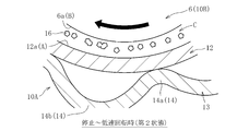
- FIG. 4 is an enlarged view of a main part of FIG. 3, and is a schematic diagram when the top foil is in a second state.
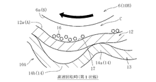
- FIG. 4 is an enlarged view of a main part of FIG. 3, and is a schematic diagram when the top foil is in a first state. It is a principal part enlarged view of the foil bearing which concerns on a modification, Comprising: It is a figure which shows typically the state before the start of use of this foil bearing.
- FIG. 1 conceptually shows a configuration of a gas turbine device called a micro gas turbine as an example of a turbo machine.
- This gas turbine device includes, as a main configuration, a turbine 1 having a blade row, a compressor 2, a generator 3, a combustor 4, and a regenerator 5, and the turbine 1 and the compressor 2 are It is attached to a shaft 6 extending in the horizontal direction and constitutes a rotor on the rotating side together with the shaft 6.
- One axial end of the shaft 6 is connected to the generator 3.
- the combustor 4 mixes fuel with compressed and heated air and burns the fuel to generate high-temperature and high-pressure gas, and the turbine 1 is rotated by the gas.
- the turbine 1 rotates, the rotational force is transmitted to the generator 3 via the shaft 6, and the generator 3 is rotationally driven.
- the electric power generated by rotating the generator 3 is output via the inverter 8. Since the gas after rotating the turbine 1 is at a relatively high temperature, the heat of the gas after combustion is regenerated by sending this gas to the regenerator 5 and exchanging heat with the compressed air before combustion. Use.
- the gas that has been subjected to heat exchange in the regenerator 5 is discharged as exhaust gas after passing through the exhaust heat recovery device 9.
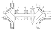
- FIG. 2 conceptually shows an example of a rotor support structure in the micro gas turbine shown in FIG.
- the radial bearings 10 are disposed at two locations spaced apart in the axial direction of the shaft 6, and the thrust bearings 30, 30 are disposed on both axial sides of the flange portion 6 b provided on the shaft 6.
- the shaft 6 is supported by the radial bearing 10 and the thrust bearing 30 so as to be rotatable in both the radial direction and the thrust direction.
- the region between the turbine 1 and the compressor 2 becomes a high temperature atmosphere because it is adjacent to the turbine 1 rotated by high temperature and high pressure gas.
- the shaft 6 rotates at a rotational speed of tens of thousands rpm or more. Therefore, as the bearings 10 and 30 used in this support structure, an air dynamic pressure bearing, particularly a foil bearing is suitable.
- foil bearing 10 which is an embodiment of the present invention and is suitable for the radial bearing 10 for the micro gas turbine will be described with reference to the drawings.
- a foil bearing suitable for the radial bearing 10 is referred to as a “foil bearing 10”.
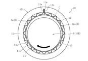
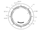
- FIG. 3 shows a cross-sectional view perpendicular to the axis of the foil bearing 10 according to one embodiment of the present invention.
- a foil bearing 10 shown in the figure is also called a bump type, and is formed of a cylindrical outer member 11 fixed to the inner periphery of a casing (not shown) and an iron-based metal material. 11 and a top foil 12 and a back foil 13 held (fixed) on the inner periphery of the outer member 11.
- the outer member 11, the top foil 12 and the back foil 13 held by the outer member 11 constitute a stationary member 10A
- the shaft 6 constitutes a rotating member 10B.
- a first bearing surface A is provided on the inner peripheral surface 12a of the top foil 12, and a wedge-shaped radial bearing gap C is provided between the outer peripheral surface 6a of the shaft 6 and the first bearing surface A when the shaft 6 rotates.
- a second bearing surface B is provided.
- both bearing surfaces A and B are formed as smooth surfaces without minute irregularities.
- the top foil 12 is formed into a cylindrical shape having a circumferential end by rounding a flexible iron-based metal strip having a thickness of about 20 to 200 ⁇ m, for example, and is bent at one end in the circumferential direction.
- the outer member 11 is held by fitting the portion 12 b into the groove 11 a of the outer member 11.
- the back foil 13 is formed into a cylindrical shape having a circumferential end by rolling a flexible iron-based metal strip having a thickness of about 20 to 200 ⁇ m.
- the bent portion 13 a formed at one end portion in the direction is fitted to the groove portion 11 a of the outer member 11 and fixed to the outer member 11.
- the back foil 13 has an elastic support portion 14 that elastically supports the top foil 12, and the elastic support portion 14 in the illustrated example is configured by alternately arranging arcuate convex portions 14a and concave portions 14b in the circumferential direction. ing.
- the top foil 12 and the back foil 13 may be provided with a retaining means to prevent the outer member 11 from coming off.
- a retaining means for example, a flange portion that is engaged with the end face of the outer member 11 in the axial direction can be employed.
- the foil member a member in which the top foil 12 and the back foil 13 are integrally provided can be used.
- the rotation direction of the shaft 6 is a direction in which the gap width of the circumferential gap between the circumferential one end and the other circumferential end of the top foil 12 and the back foil 13 is increased. That is, the foil bearing 10 shown in FIG. 3 supports the shaft 6 that rotates clockwise as indicated by a black arrow in the drawing.
- the shaft 6 when the shaft 6 rotates, the space between the first bearing surface A provided on the inner peripheral surface 12a of the top foil 12 and the second bearing surface B provided on the outer peripheral surface 6a of the shaft 6 is increased. A wedge-shaped radial bearing gap C is formed.
- the rotational speed of the shaft 6 is increased and the pressure of the air film generated in the radial bearing gap C is sufficiently increased, the shaft 6 is supported in a non-contact manner so as to be rotatable in the radial direction with respect to the outer member 11.
- the flexible top foil 12 While the shaft 6 is rotating, the flexible top foil 12 is appropriately elastically deformed according to changes in the load (air film pressure) acting on the first bearing surface A, the ambient temperature, etc.
- the gap width of the radial bearing gap C is automatically adjusted to an appropriate width according to the operating conditions. By such a function of automatically adjusting the gap width, the rotation of the shaft 6 is stably supported.
- the radial width of the radial bearing gap C is exaggerated for easy understanding.
- the top foil 12 is elastically supported by the elastic support portion 14 provided on the back foil 13, the top foil 12 and the back foil 13 (elastic support portion 14), and further, the back foil 13 and the outer member 11.
- the automatic adjustment function of the radial width of the radial bearing gap C can be enhanced, and vibration generated with the rotation of the shaft 6 can be effectively damped. . Therefore, the radial width of the radial bearing gap C can be managed within an appropriate range even under severe operating conditions such as high temperature and high speed rotation, and the rotation of the shaft 6 is supported more stably.
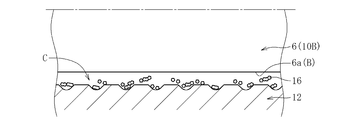
- a powder 16 (hereinafter, referred to as “ Lubricating powder 16 ”) is interposed.
- the lubricating powder 16 is made of a material different from the base material of the shaft 6 and the top foil 12 and is not melted or decomposed in a high temperature atmosphere where the foil bearing 10 is used.
- the lubricating powder 16 is oxidized.
- Iron powder is used.
- the iron oxide powder as the lubricating powder 16 is the top as the two bearing surfaces A and B are repeatedly in sliding contact after the foil bearing 10 starts operating until the shaft 6 reaches a steady rotation state.
- Metal wear powder (iron-based powder) generated by wear of at least one of the base material of the foil 12 and the shaft 6 is oxidized by touching the air in the radial bearing gap C.
- the top foil 12 is elastically deformed in the width direction of the bearing gap (radial direction in the present embodiment) according to the pressure of the air film generated in the radial bearing gap C at least partially.
- a first state (see FIG. 5) in which a holding part 17 capable of holding the lubricating powder 16 interposed between the bearing surfaces A and B is formed, and a second state in which the holding part 17 substantially disappears ( Between the second state and the first state as the pressure of the air film increases (from the first state to the second state as the pressure of the air film decreases). To be migrated).
- the top foil 12 (first bearing surface A) receives the pressure of the air film.
- At least a portion (here, a portion disposed on the inner diameter side of the concave portion 14b constituting the elastic support portion 14) is elastically deformed radially outward to form a concave holding portion 17, and this holding portion 17, the lubricating powder 16 interposed between the bearing surfaces A and B is held (see FIG. 5).
- the first bearing surface A of the top foil 12 has a smooth cylindrical surface shape (the holding portion 17 substantially disappears), and the lubricating powder 16 freely disperses and floats between the bearing surfaces A and B. (See FIG. 4).
- the first bearing surface A is changed to the second bearing surface B. And can be preferentially brought into contact with the lubricating powder 16 interposed between the bearing surfaces A and B.
- the frictional force between the bearing surfaces A and B can be reduced to achieve low torque.
- transformation and seizure of both bearing surfaces A and B accompanying this can also be prevented effectively. .
- the average particle size of the lubricating powder 16 interposed between the bearing surfaces A and B is equal to or greater than the surface roughness of both the bearing surfaces A and B (the arithmetic average roughness specified in JIS B 0601), and the shaft It is preferable that the thickness of the air film formed in the radial bearing gap C is equal to or less than the thickness of the air bearing 6 at the time of steady rotation (fluid lubrication region).
- the stationary side member and the rotating side member both bearing surfaces A and B
- the top foil 12 is in a second state (see FIG. 4) in which the lubricating powder 16 can be freely dispersed and suspended between the bearing surfaces A and B.
- the lubricating powder 16 interposed between the bearing surfaces A and B functions as a spacer, so that not only the frictional force between the bearing surfaces is reduced, but also a space is created between the bearing surfaces A and B. This makes it easier to draw air between the bearing surfaces A and B.
- the foil bearing 10 starts operating, a steady rotation state can be quickly realized without requiring large energy. Accordingly, the starting torque can be greatly reduced, and the rotational speed required to support the shaft 6 in a non-contact manner is reduced, so that the load on both the bearing surfaces A and B is reduced and the durability is improved.
- the lubricating powder 16 is not always held by the holding portion 17 during steady rotation of the shaft 6, that is, when the top foil 12 is in the first state (see FIG. 5). It is thought that it adheres to one or both of both bearing surfaces A and B, or floats and flows in the radial bearing gap C.
- the foil bearing 10 employs air having a lower viscosity than a liquid such as lubricating oil as the lubricating fluid, the lubricating powder 16 adhering to the bearing surfaces A and B causes the flow force of the lubricating fluid. Even if it receives, the lubricating powder 16 is hard to peel off from the bearing surfaces A and B.
- the foil bearing 10 when the start / stop is repeated, the sliding contact between the lubricating powder 16 and both the bearing surfaces A and B, and the lubricating powder by the both bearing surfaces A and B are performed. Since the pressurization and the like of 16 are repeated, it is considered that the lubricating powder 16 adheres and accumulates on one or both of the bearing surfaces A and B to form a lubricating coating. Thereby, low torque can be realized in all lubrication regions (rotational speed regions). Accordingly, the foil bearing 10 having a lower torque and a longer life can be realized.
- the lubricating powder 16 is simply interposed between the bearing surfaces A and B without providing the top foil 12 with the function of switching the holding / non-holding of the lubricating powder 16 as in the present invention. It is possible to reduce the torque of the foil bearing 10 and the like. However, if the lubricating powder 16 is excessively interposed between the bearing surfaces A and B, the volume ratio of the lubricating powder 16 to the air in the radial bearing gap C is increased, particularly during steady rotation. There is a possibility that the rigidity of the air film formed in the radial bearing gap C will be reduced, that is, the supporting ability may be reduced.
- the bearing surfaces A and B may bite the lubricating powder 16 and may adversely affect the bearing function itself. Therefore, as shown in FIG. 5, during steady rotation (fluid lubrication region), the lubricating powder 16 is held by the holding portion 17, and the supply amount (dispersion amount) of the lubricating powder 16 to the radial bearing gap C is maintained.
- a sufficient amount of the lubricating powder 16 can be interposed between the bearing surfaces A and B in the stop to low speed rotation state (mixed lubrication region / boundary lubrication region) shown in FIG. It is preferable to give the function to the top foil 12.
- the top foil 12 is formed of a flexible metal thin plate and can be arbitrarily elastically deformed according to the pressure of the air film, the above-described top foil 12 can be obtained by simply adjusting the shape of the elastic support portion 14 and the like. The effects can be enjoyed easily and effectively.
- FIG. 6A is an example thereof, and a plurality of minute protrusions 18 are provided on the first bearing surface A of the top foil 12.
- the contact area between the bearing surfaces A and B can be reduced to achieve low torque, and the space between the bearing surfaces A and B is formed, so that both bearing surfaces A and B are formed. Since it becomes easy to draw air between B, it becomes possible to reduce starting torque. Further, at the time of sliding contact between both the bearing surfaces A and B, a high surface pressure acts on the protrusion 18, so that the wear powder and, consequently, the lubricating powder 16 are quickly interposed between the both bearing surfaces A and B. (See FIG. 6B). In addition, if the height and the number of installations of the protrusions 18 are adjusted, the particle diameter and amount of the lubricating powder 16 (the lubricating powder 16 made of oxide of wear powder) to be interposed between the bearing surfaces A and B. Can be controlled.
- At least one of the first bearing surface A and the second bearing surface B may be provided on a lubricating coating formed on the base material (base material surface). That is, a lubricating coating may be provided on a portion of the inner peripheral surface 12a of the top foil 12 and the outer peripheral surface 6a of the shaft 6 that faces at least one radial bearing gap C, and the bearing surface may be configured by this lubricating coating. In this way, in particular, both bearings at the start of use of the foil bearing 10 in which the shaft 6 and the top foil 12 are formed of the same material and the lubricating powder 16 is not interposed between the bearing surfaces A and B.
- both bearing surfaces A and B can be effectively prevented from being severely worn and causing fatal defects such as adhesion at the sliding contact portions of both. it can.
- the lubricating coating does not require special wear resistance and may be worn at an early stage. Since the abrasion powder of the lubricating coating exhibits a lubricating action, even if the base material of the shaft 6 and the top foil 12 is worn, the situation where the wear becomes mild wear and leads to adhesion is avoided. The generated fine wear powder of the base material is immediately oxidized and functions as the lubricating powder 16.
- lubricating coatings can be employed.
- powders for example, molybdenum disulfide powder, tungsten disulfide, etc.
- abrasion powder functions as the lubricating powder 16.
- a film having excellent wear resistance such as a DLC film Can be adopted.
- the DLC film is formed, it is preferably formed on the outer peripheral surface 6a of the shaft 6, not on the inner peripheral surface 12a of the top foil 12 formed of a thin metal plate.
- a protrusion 18 can be provided.
- the lubricating powder 16 interposed between the bearing surfaces A and B may include a solid lubricant powder different from the wear powder of the top foil 12 and the base material of the shaft 6. . That is, solid lubricant powder may be interposed between the bearing surfaces A and B of the foil bearing 10 (new foil bearing 10) before use. In this way, since the lubricating powder 16 can be interposed between the bearing surfaces A and B from the start of use of the new foil bearing 10, the above-described effects can be enjoyed effectively.
- the average particle size is equal to or greater than the surface roughness of both bearing surfaces A and B (arithmetic average roughness specified in JIS B 0601) and is steady. It is preferable to use one having a thickness equal to or less than the thickness of the air film formed in the radial bearing gap C during rotation.
- the solid lubricant powder when solid lubricant powder is interposed between the bearing surfaces A and B in advance, if the hardness is higher than the base material hardness of the top foil 12 or the shaft 6, the solid lubricant powder functions as abrasive grains. In addition, the generation of the wear powder of the base material and the oxide powder (lubricating powder 16) thereof is promoted. On the other hand, if the hardness of the solid lubricant powder is about the same as that of the top foil 12 or the base material of the shaft 6 or lower than that of the base material, there is an advantage that a reduction in torque can be realized from the beginning of use of the foil bearing 10. From the above, there is no particular restriction on the solid lubricant powder used in this case.
- powder of metal oxide such as iron oxide (Fe 2 O 3 ) or alumina (Al 2 O 3 ), molybdenum disulfide (MoS) 2 ), powders of sulfides such as tungsten disulfide (WS 2 ), powders of soft metals such as copper (Cu), silver (Ag), tin (Sn), zinc (Zn), carbon represented by graphite powder System powders
- MoS molybdenum disulfide
- WS 2 powders of sulfides
- powders of soft metals such as copper (Cu), silver (Ag), tin (Sn), zinc (Zn)
- carbon represented by graphite powder System powders can be used.
- the solid lubricant powder exemplified above only one kind may be used, or a plurality of kinds may be mixed and used.
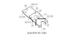
- FIG. 7 shows an example of a leaf-type foil bearing 10 that supports a radial load, and includes an outer member 11 and a plurality (eight in the illustrated example) of leaves 20 fixed to the outer member 11. 10 A of stationary side members are comprised.
- Each leaf 20 has a rear end 22 provided with a bent portion 23 fixed to the groove portion 11a of the outer member 11, and a front end 21 which is separated from the rear end 22 in the circumferential direction and becomes a free end, A region including the front end 21 of the leaf 20 functions as the top foil 12, and a region including the rear end 22 of each leaf 20 functions as the elastic support portion 14.
- the first bearing surface A provided on the inner diameter surface on the front end 20a side of each leaf 20 and the outer peripheral surface 6a (second bearing surface B) of the shaft 6 opposed to the first bearing surface A are disposed.
- a wedge-shaped radial bearing gap C is formed, and the shaft 6 is supported in the radial direction by the pressure of the air film generated in each radial bearing gap C.
- each leaf 20 functioning as the top foil 12 has a radial bearing gap C as in the bump type foil bearing 10 mainly shown in FIGS.
- the lubricating powder 16 is interposed between the bearing surfaces A and B, as in the bump type foil bearing 10 shown in FIG. Can do.
- the top foil 12 (leaf 20) and the shaft are associated with the sliding contact of both the bearing surfaces A and B.
- Oxide (only) of wear powder generated by wear of at least one of the base material of 6 may contain a solid lubricant powder different from the wear powder of the base material of leaf 20 and shaft 6 May be used.
- at least one of both bearing surfaces A and B may be provided with a minute projection 18 (see FIG.
- each leaf 20 is accompanied by an increase in the pressure of the air film generated in the radial bearing gap C (as the front end 21 side of the leaf 20 is elastically deformed radially outward).
- a holding portion 17 formed between two adjacent leaves 20 and 20 may be provided with a drawing portion 24 that can positively draw the lubricating powder 16 interposed between both bearing surfaces A and B.
- the manner in which the pulling force acts is indicated by a black arrow in FIG. 8B).
- a V-shaped notch formed on the rear end 22 side of the leaf 20 (more specifically, a V-shaped notch whose width is gradually reduced toward the front side in the rotational direction of the shaft 6).
- the retraction part 24 is comprised by.
- the present invention is applied to the foil bearing 10 in which the top foil 12 and the elastic support portion 14 are provided on the outer member 11 constituting the stationary member 10A.
- the present invention is applied to the top foil 12 and the elastic support portion 14.
- the present invention can be applied to the foil bearing 10 in which the outer member 11 constitutes the rotation side member 10B and the shaft 6 constitutes the stationary side member 10A (not shown).
- the present invention is not limited to the type of foil bearing 10 that supports a radial load as described above, but also a type of foil bearing that supports a thrust load (for example, the thrust bearing shown in FIG. 2). 30).
- the foil bearing according to the present invention can be preferably used not only for supporting a rotor of a turbo machine such as a micro gas turbine but also for supporting another rotating body.
- a new foil bearing is prepared as a specimen, and solid lubricant powder is interposed in advance between the inner peripheral surface of the top foil and the outer peripheral surface of the shaft (between both bearing surfaces), and then the foil bearing is operated for a predetermined time.
- solid lubricant powder As a result, it was confirmed and investigated how much the amount of wear on the bearing surface (base material) varies depending on the type of solid lubricant powder interposed between both bearing surfaces. The results of the investigation are shown in FIG.
- the top foil constituting the foil bearing and the shaft inserted into the inner periphery thereof were both made of an iron-based metal material.
- solid lubricant powder alumina, iron oxide, copper, silver, and molybdenum disulfide powder were prepared.
- the top foil does not cause fatal defects such as breakage due to sliding contact with the shaft, and the wear amount of the base material (total weight of the wear powder) ) Can be suppressed within a range that does not adversely affect the bearing performance of the foil bearing.
- the soft metal powder especially copper powder is effective in reducing the torque and extending the life of the foil bearing.
- the wear amount of the base material was the smallest when iron oxide powder was used as the solid lubricant powder.
- the top foil and shaft are made of iron-based metal material, so the iron oxide powder previously interposed between both bearing surfaces as the solid lubricant powder is the base material of the top foil and shaft.
- This powder is the same type as the lubricating powder produced by oxidation of the wear powder. Therefore, it can be said that the oxide of the top foil and the shaft base material contributes particularly effectively in reducing the friction of both bearing surfaces, that is, reducing the torque and extending the life of the foil bearing.
- the solid lubricant powder was interposed between the bearing surfaces.
- the bearing surfaces is composed of a lubricant film in which the solid lubricant powder is dispersed, It is thought that the effect can be enjoyed.
Landscapes
- Engineering & Computer Science (AREA)
- General Engineering & Computer Science (AREA)
- Mechanical Engineering (AREA)
- Physics & Mathematics (AREA)
- Fluid Mechanics (AREA)
- Support Of The Bearing (AREA)
- Supercharger (AREA)
- Sliding-Contact Bearings (AREA)
Abstract
L'invention porte sur un palier à feuilles (10), lequel palier comprend une face supérieure (12) formée à partir d'une feuille métallique souple, et dans lequel, quand un arbre (6) tourne, un film d'air est formé dans un espace de palier radial (C) entre une première surface de palier (A) située sur la feuille supérieure (12) et une seconde surface de palier (B) située sur l'arbre (6), de telle sorte que l'arbre (6) est supporté par la pression du film. Dans ce palier à feuilles (10), une poudre lubrifiante (16) est interposée entre les deux surfaces de palier (A et B). La feuille supérieure (12) est déformée partiellement élastiquement dans la direction de la largeur de l'espace de palier radial (C) en fonction de la pression du film d'air généré dans l'espace de palier radial (C), de façon à passer en va-et-vient entre un premier état, dans lequel une partie de support (17), apte à supporter la poudre lubrifiante (16), est formée, et un second état, dans lequel la partie de support (17) disparaît sensiblement, et à passer à partir du second état jusqu'au premier état quand la pression du film d'air augmente.
Priority Applications (3)
| Application Number | Priority Date | Filing Date | Title |
|---|---|---|---|
| CN201580014265.XA CN106104029B (zh) | 2014-03-19 | 2015-03-19 | 箔片轴承 |
| EP15764958.3A EP3128191B1 (fr) | 2014-03-19 | 2015-03-19 | Palier à feuilles |
| US15/126,635 US9822816B2 (en) | 2014-03-19 | 2015-03-19 | Foil bearing |
Applications Claiming Priority (4)
| Application Number | Priority Date | Filing Date | Title |
|---|---|---|---|
| JP2014056407 | 2014-03-19 | ||
| JP2014-056407 | 2014-03-19 | ||
| JP2015044274A JP6591179B2 (ja) | 2014-03-19 | 2015-03-06 | フォイル軸受 |
| JP2015-044274 | 2015-03-06 |
Publications (1)
| Publication Number | Publication Date |
|---|---|
| WO2015141806A1 true WO2015141806A1 (fr) | 2015-09-24 |
Family
ID=54144768
Family Applications (1)
| Application Number | Title | Priority Date | Filing Date |
|---|---|---|---|
| PCT/JP2015/058364 WO2015141806A1 (fr) | 2014-03-19 | 2015-03-19 | Palier à feuilles |
Country Status (5)
| Country | Link |
|---|---|
| US (1) | US9822816B2 (fr) |
| EP (1) | EP3128191B1 (fr) |
| JP (1) | JP6591179B2 (fr) |
| CN (1) | CN106104029B (fr) |
| WO (1) | WO2015141806A1 (fr) |
Cited By (4)
| Publication number | Priority date | Publication date | Assignee | Title |
|---|---|---|---|---|
| ITUB20154891A1 (it) * | 2015-10-20 | 2017-04-20 | Univ Degli Studi Genova | Unita micro-turbogas perfezionato |
| CN108138843A (zh) * | 2015-10-16 | 2018-06-08 | Ntn株式会社 | 箔片轴承 |
| EP3369952A4 (fr) * | 2015-10-28 | 2019-07-03 | NTN Corporation | Palier à feuilles, son procédé de fabrication et produit intermédiaire de palier à feuilles |
| TWI676735B (zh) * | 2015-05-19 | 2019-11-11 | 羅立峰 | 小微型燃氣輪發電機 |
Families Citing this family (5)
| Publication number | Priority date | Publication date | Assignee | Title |
|---|---|---|---|---|
| JP6545605B2 (ja) * | 2015-11-19 | 2019-07-17 | Ntn株式会社 | フォイル軸受 |
| US20170298830A1 (en) * | 2016-04-18 | 2017-10-19 | General Electric Company | Oil-free gas turbine engine |
| US20190120291A1 (en) * | 2017-10-24 | 2019-04-25 | Hamilton Sundstrand Corporation | Air bearing |
| JP2021131135A (ja) * | 2020-02-20 | 2021-09-09 | パナソニックIpマネジメント株式会社 | 軸受構造 |
| JP7392620B2 (ja) * | 2020-09-30 | 2023-12-06 | 株式会社豊田自動織機 | 遠心圧縮機 |
Citations (3)
| Publication number | Priority date | Publication date | Assignee | Title |
|---|---|---|---|---|
| WO2006084587A1 (fr) * | 2005-02-11 | 2006-08-17 | Schaeffler Kg | Systeme de roulement, en particulier pour des paliers a roulement et des paliers lisses |
| JP2009293733A (ja) * | 2008-06-06 | 2009-12-17 | Jtekt Corp | 遠心圧縮機 |
| JP2013032797A (ja) * | 2011-08-01 | 2013-02-14 | Ntn Corp | フォイル軸受 |
Family Cites Families (14)
| Publication number | Priority date | Publication date | Assignee | Title |
|---|---|---|---|---|
| US4223958A (en) * | 1978-12-29 | 1980-09-23 | Mechanical Technology Incorporated | Modular compliant hydrodynamic bearing with overlapping bearing sheet |
| US4459047A (en) * | 1979-04-27 | 1984-07-10 | The Garrett Corporation | Foil bearing surfaces and method of making same |
| US4435839A (en) * | 1982-09-21 | 1984-03-06 | The Garrett Corporation | Foil bearing rubbing surface coating application methods |
| JPH01242817A (ja) * | 1988-03-23 | 1989-09-27 | Osaka Sangyo Univ | 流体力学的箔軸受 |
| US6698930B2 (en) * | 2000-12-01 | 2004-03-02 | Mitsubishi Heavy Industries, Ltd. | Foil gas bearing |
| JP2003262222A (ja) | 2002-03-08 | 2003-09-19 | Ntn Corp | フォイル軸受 |
| US7297367B2 (en) * | 2004-01-28 | 2007-11-20 | Honeywell International, Inc. | Inorganic solid lubricant for high temperature foil bearing |
| KR100604132B1 (ko) * | 2004-05-03 | 2006-07-25 | 주식회사 뉴로스 | 포일 에어베어링 |
| KR100849075B1 (ko) * | 2006-08-29 | 2008-07-30 | 한국과학기술연구원 | 고속 터보 기기의 무급유 베어링용 중온 코팅제 및 그 코팅방법 |
| KR100803968B1 (ko) * | 2006-10-13 | 2008-02-15 | 재단법인 포항산업과학연구원 | 윤활코팅분말 및 그 제조방법 |
| US8356413B2 (en) * | 2006-10-24 | 2013-01-22 | Honeywell International Inc. | Thermally sprayed structures for foil bearings |
| CN100588846C (zh) * | 2007-05-30 | 2010-02-10 | 哈尔滨工业大学 | 可调悬臂式动压气体弹性箔片轴承 |
| US8158205B2 (en) * | 2009-06-05 | 2012-04-17 | Honeywell International Inc. | Methods of forming solid lubricant coatings on substrates |
| CN102954102B (zh) * | 2012-11-05 | 2015-04-08 | 湖南大学 | 内装金属颗粒的高阻尼箔片动压气体轴承 |
-
2015
- 2015-03-06 JP JP2015044274A patent/JP6591179B2/ja active Active
- 2015-03-19 EP EP15764958.3A patent/EP3128191B1/fr active Active
- 2015-03-19 CN CN201580014265.XA patent/CN106104029B/zh active Active
- 2015-03-19 WO PCT/JP2015/058364 patent/WO2015141806A1/fr active Application Filing
- 2015-03-19 US US15/126,635 patent/US9822816B2/en active Active
Patent Citations (3)
| Publication number | Priority date | Publication date | Assignee | Title |
|---|---|---|---|---|
| WO2006084587A1 (fr) * | 2005-02-11 | 2006-08-17 | Schaeffler Kg | Systeme de roulement, en particulier pour des paliers a roulement et des paliers lisses |
| JP2009293733A (ja) * | 2008-06-06 | 2009-12-17 | Jtekt Corp | 遠心圧縮機 |
| JP2013032797A (ja) * | 2011-08-01 | 2013-02-14 | Ntn Corp | フォイル軸受 |
Non-Patent Citations (1)
| Title |
|---|
| See also references of EP3128191A4 * |
Cited By (10)
| Publication number | Priority date | Publication date | Assignee | Title |
|---|---|---|---|---|
| TWI676735B (zh) * | 2015-05-19 | 2019-11-11 | 羅立峰 | 小微型燃氣輪發電機 |
| CN108138843A (zh) * | 2015-10-16 | 2018-06-08 | Ntn株式会社 | 箔片轴承 |
| US20190078613A1 (en) * | 2015-10-16 | 2019-03-14 | Ntn Corporation | Foil bearing |
| EP3364059A4 (fr) * | 2015-10-16 | 2019-06-12 | NTN Corporation | Palier à feuilles |
| US10480568B2 (en) * | 2015-10-16 | 2019-11-19 | Ntn Corporation | Foil bearing |
| CN108138843B (zh) * | 2015-10-16 | 2020-03-03 | Ntn株式会社 | 箔片轴承 |
| ITUB20154891A1 (it) * | 2015-10-20 | 2017-04-20 | Univ Degli Studi Genova | Unita micro-turbogas perfezionato |
| WO2017067982A1 (fr) * | 2015-10-20 | 2017-04-27 | Universita' Degli Studi Di Genova | Unité de micro-turbine à gaz améliorée et son procédé de fonctionnement |
| EP3369952A4 (fr) * | 2015-10-28 | 2019-07-03 | NTN Corporation | Palier à feuilles, son procédé de fabrication et produit intermédiaire de palier à feuilles |
| US10428865B2 (en) | 2015-10-28 | 2019-10-01 | Ntn Corporation | Foil bearing, production method therefor, and intermediate product of foil bearing |
Also Published As
| Publication number | Publication date |
|---|---|
| US20170089389A1 (en) | 2017-03-30 |
| EP3128191A4 (fr) | 2018-02-21 |
| CN106104029A (zh) | 2016-11-09 |
| CN106104029B (zh) | 2018-12-04 |
| US9822816B2 (en) | 2017-11-21 |
| JP6591179B2 (ja) | 2019-10-16 |
| JP2015194252A (ja) | 2015-11-05 |
| EP3128191B1 (fr) | 2021-05-05 |
| EP3128191A1 (fr) | 2017-02-08 |
Similar Documents
| Publication | Publication Date | Title |
|---|---|---|
| JP6591179B2 (ja) | フォイル軸受 | |
| WO2014098005A1 (fr) | Palier à feuilles | |
| JP6113444B2 (ja) | フォイル軸受 | |
| JP2012092969A (ja) | フォイル軸受 | |
| JP6104597B2 (ja) | フォイル軸受 | |
| JP2013061024A (ja) | スラストフォイル軸受 | |
| US20080108013A1 (en) | Dental handpiece with air-foil bearings | |
| US10480568B2 (en) | Foil bearing | |
| JP6104596B2 (ja) | フォイル軸受 | |
| JP5840423B2 (ja) | フォイル軸受 | |
| JP2013053645A (ja) | スラストフォイル軸受 | |
| JP2013032797A (ja) | フォイル軸受 | |
| JP2019082195A (ja) | フォイル軸受、フォイル軸受ユニット、ターボ機械 | |
| JP6144222B2 (ja) | フォイル軸受 | |
| WO2020195488A1 (fr) | Palier à feuilles de poussée, unité de support de feuille, turbomachine et feuille | |
| JP6622054B2 (ja) | フォイル軸受 | |
| JP2012072817A (ja) | フォイル軸受 | |
| KR100782374B1 (ko) | 정밀 래디알 포일 베어링 | |
| JP2017075680A (ja) | フォイル軸受 | |
| JP6219489B2 (ja) | フォイル軸受 | |
| WO2017065176A1 (fr) | Palier à feuilles | |
| JP6324774B2 (ja) | フォイル軸受及びこれを備えたターボ機械 | |
| JP6440999B2 (ja) | フォイル軸受及びこれに設けられるフォイル | |
| JP2021067353A (ja) | フォイル軸受およびこれを備えた回転機械 | |
| WO2017051658A1 (fr) | Palier à feuilles et son procédé de fabrication |
Legal Events
| Date | Code | Title | Description |
|---|---|---|---|
| 121 | Ep: the epo has been informed by wipo that ep was designated in this application |
Ref document number: 15764958 Country of ref document: EP Kind code of ref document: A1 |
|
| WWE | Wipo information: entry into national phase |
Ref document number: 15126635 Country of ref document: US |
|
| NENP | Non-entry into the national phase |
Ref country code: DE |
|
| REEP | Request for entry into the european phase |
Ref document number: 2015764958 Country of ref document: EP |
|
| WWE | Wipo information: entry into national phase |
Ref document number: 2015764958 Country of ref document: EP |