WO2015141458A1 - コンバインドサイクルプラント、その制御方法、及びその制御装置 - Google Patents
コンバインドサイクルプラント、その制御方法、及びその制御装置 Download PDFInfo
- Publication number
- WO2015141458A1 WO2015141458A1 PCT/JP2015/056182 JP2015056182W WO2015141458A1 WO 2015141458 A1 WO2015141458 A1 WO 2015141458A1 JP 2015056182 W JP2015056182 W JP 2015056182W WO 2015141458 A1 WO2015141458 A1 WO 2015141458A1
- Authority
- WO
- WIPO (PCT)
- Prior art keywords
- steam
- turbine
- steam turbine
- flow rate
- line
- Prior art date
- Legal status (The legal status is an assumption and is not a legal conclusion. Google has not performed a legal analysis and makes no representation as to the accuracy of the status listed.)
- Ceased
Links
Images


Classifications
-
- F—MECHANICAL ENGINEERING; LIGHTING; HEATING; WEAPONS; BLASTING
- F01—MACHINES OR ENGINES IN GENERAL; ENGINE PLANTS IN GENERAL; STEAM ENGINES
- F01K—STEAM ENGINE PLANTS; STEAM ACCUMULATORS; ENGINE PLANTS NOT OTHERWISE PROVIDED FOR; ENGINES USING SPECIAL WORKING FLUIDS OR CYCLES
- F01K7/00—Steam engine plants characterised by the use of specific types of engine; Plants or engines characterised by their use of special steam systems, cycles or processes; Control means specially adapted for such systems, cycles or processes; Use of withdrawn or exhaust steam for feed-water heating
- F01K7/16—Steam engine plants characterised by the use of specific types of engine; Plants or engines characterised by their use of special steam systems, cycles or processes; Control means specially adapted for such systems, cycles or processes; Use of withdrawn or exhaust steam for feed-water heating the engines being only of turbine type
- F01K7/165—Controlling means specially adapted therefor
-
- F—MECHANICAL ENGINEERING; LIGHTING; HEATING; WEAPONS; BLASTING
- F01—MACHINES OR ENGINES IN GENERAL; ENGINE PLANTS IN GENERAL; STEAM ENGINES
- F01D—NON-POSITIVE DISPLACEMENT MACHINES OR ENGINES, e.g. STEAM TURBINES
- F01D19/00—Starting of machines or engines; Regulating, controlling, or safety means in connection therewith
-
- F—MECHANICAL ENGINEERING; LIGHTING; HEATING; WEAPONS; BLASTING
- F01—MACHINES OR ENGINES IN GENERAL; ENGINE PLANTS IN GENERAL; STEAM ENGINES
- F01K—STEAM ENGINE PLANTS; STEAM ACCUMULATORS; ENGINE PLANTS NOT OTHERWISE PROVIDED FOR; ENGINES USING SPECIAL WORKING FLUIDS OR CYCLES
- F01K11/00—Plants characterised by the engines being structurally combined with boilers or condensers
- F01K11/02—Plants characterised by the engines being structurally combined with boilers or condensers the engines being turbines
-
- F—MECHANICAL ENGINEERING; LIGHTING; HEATING; WEAPONS; BLASTING
- F01—MACHINES OR ENGINES IN GENERAL; ENGINE PLANTS IN GENERAL; STEAM ENGINES
- F01K—STEAM ENGINE PLANTS; STEAM ACCUMULATORS; ENGINE PLANTS NOT OTHERWISE PROVIDED FOR; ENGINES USING SPECIAL WORKING FLUIDS OR CYCLES
- F01K13/00—General layout or general methods of operation of complete plants
- F01K13/003—Arrangements for measuring or testing
-
- F—MECHANICAL ENGINEERING; LIGHTING; HEATING; WEAPONS; BLASTING
- F01—MACHINES OR ENGINES IN GENERAL; ENGINE PLANTS IN GENERAL; STEAM ENGINES
- F01K—STEAM ENGINE PLANTS; STEAM ACCUMULATORS; ENGINE PLANTS NOT OTHERWISE PROVIDED FOR; ENGINES USING SPECIAL WORKING FLUIDS OR CYCLES
- F01K13/00—General layout or general methods of operation of complete plants
- F01K13/02—Controlling, e.g. stopping or starting
-
- F—MECHANICAL ENGINEERING; LIGHTING; HEATING; WEAPONS; BLASTING
- F01—MACHINES OR ENGINES IN GENERAL; ENGINE PLANTS IN GENERAL; STEAM ENGINES
- F01K—STEAM ENGINE PLANTS; STEAM ACCUMULATORS; ENGINE PLANTS NOT OTHERWISE PROVIDED FOR; ENGINES USING SPECIAL WORKING FLUIDS OR CYCLES
- F01K23/00—Plants characterised by more than one engine delivering power external to the plant, the engines being driven by different fluids
- F01K23/02—Plants characterised by more than one engine delivering power external to the plant, the engines being driven by different fluids the engine cycles being thermally coupled
- F01K23/06—Plants characterised by more than one engine delivering power external to the plant, the engines being driven by different fluids the engine cycles being thermally coupled combustion heat from one cycle heating the fluid in another cycle
- F01K23/10—Plants characterised by more than one engine delivering power external to the plant, the engines being driven by different fluids the engine cycles being thermally coupled combustion heat from one cycle heating the fluid in another cycle with exhaust fluid of one cycle heating the fluid in another cycle
-
- F—MECHANICAL ENGINEERING; LIGHTING; HEATING; WEAPONS; BLASTING
- F01—MACHINES OR ENGINES IN GENERAL; ENGINE PLANTS IN GENERAL; STEAM ENGINES
- F01K—STEAM ENGINE PLANTS; STEAM ACCUMULATORS; ENGINE PLANTS NOT OTHERWISE PROVIDED FOR; ENGINES USING SPECIAL WORKING FLUIDS OR CYCLES
- F01K7/00—Steam engine plants characterised by the use of specific types of engine; Plants or engines characterised by their use of special steam systems, cycles or processes; Control means specially adapted for such systems, cycles or processes; Use of withdrawn or exhaust steam for feed-water heating
- F01K7/16—Steam engine plants characterised by the use of specific types of engine; Plants or engines characterised by their use of special steam systems, cycles or processes; Control means specially adapted for such systems, cycles or processes; Use of withdrawn or exhaust steam for feed-water heating the engines being only of turbine type
- F01K7/22—Steam engine plants characterised by the use of specific types of engine; Plants or engines characterised by their use of special steam systems, cycles or processes; Control means specially adapted for such systems, cycles or processes; Use of withdrawn or exhaust steam for feed-water heating the engines being only of turbine type the turbines having inter-stage steam heating
- F01K7/24—Control or safety means specially adapted therefor
-
- F—MECHANICAL ENGINEERING; LIGHTING; HEATING; WEAPONS; BLASTING
- F02—COMBUSTION ENGINES; HOT-GAS OR COMBUSTION-PRODUCT ENGINE PLANTS
- F02C—GAS-TURBINE PLANTS; AIR INTAKES FOR JET-PROPULSION PLANTS; CONTROLLING FUEL SUPPLY IN AIR-BREATHING JET-PROPULSION PLANTS
- F02C3/00—Gas-turbine plants characterised by the use of combustion products as the working fluid
- F02C3/04—Gas-turbine plants characterised by the use of combustion products as the working fluid having a turbine driving a compressor
-
- F—MECHANICAL ENGINEERING; LIGHTING; HEATING; WEAPONS; BLASTING
- F02—COMBUSTION ENGINES; HOT-GAS OR COMBUSTION-PRODUCT ENGINE PLANTS
- F02C—GAS-TURBINE PLANTS; AIR INTAKES FOR JET-PROPULSION PLANTS; CONTROLLING FUEL SUPPLY IN AIR-BREATHING JET-PROPULSION PLANTS
- F02C6/00—Plural gas-turbine plants; Combinations of gas-turbine plants with other apparatus; Adaptations of gas-turbine plants for special use
- F02C6/18—Plural gas-turbine plants; Combinations of gas-turbine plants with other apparatus; Adaptations of gas-turbine plants for special use using the waste heat of gas-turbine plants outside the plants themselves, e.g. gas-turbine power heat plants
-
- F—MECHANICAL ENGINEERING; LIGHTING; HEATING; WEAPONS; BLASTING
- F05—INDEXING SCHEMES RELATING TO ENGINES OR PUMPS IN VARIOUS SUBCLASSES OF CLASSES F01-F04
- F05D—INDEXING SCHEME FOR ASPECTS RELATING TO NON-POSITIVE-DISPLACEMENT MACHINES OR ENGINES, GAS-TURBINES OR JET-PROPULSION PLANTS
- F05D2220/00—Application
- F05D2220/30—Application in turbines
- F05D2220/31—Application in turbines in steam turbines
-
- F—MECHANICAL ENGINEERING; LIGHTING; HEATING; WEAPONS; BLASTING
- F05—INDEXING SCHEMES RELATING TO ENGINES OR PUMPS IN VARIOUS SUBCLASSES OF CLASSES F01-F04
- F05D—INDEXING SCHEME FOR ASPECTS RELATING TO NON-POSITIVE-DISPLACEMENT MACHINES OR ENGINES, GAS-TURBINES OR JET-PROPULSION PLANTS
- F05D2220/00—Application
- F05D2220/30—Application in turbines
- F05D2220/32—Application in turbines in gas turbines
-
- F—MECHANICAL ENGINEERING; LIGHTING; HEATING; WEAPONS; BLASTING
- F05—INDEXING SCHEMES RELATING TO ENGINES OR PUMPS IN VARIOUS SUBCLASSES OF CLASSES F01-F04
- F05D—INDEXING SCHEME FOR ASPECTS RELATING TO NON-POSITIVE-DISPLACEMENT MACHINES OR ENGINES, GAS-TURBINES OR JET-PROPULSION PLANTS
- F05D2220/00—Application
- F05D2220/70—Application in combination with
- F05D2220/72—Application in combination with a steam turbine
-
- F—MECHANICAL ENGINEERING; LIGHTING; HEATING; WEAPONS; BLASTING
- F05—INDEXING SCHEMES RELATING TO ENGINES OR PUMPS IN VARIOUS SUBCLASSES OF CLASSES F01-F04
- F05D—INDEXING SCHEME FOR ASPECTS RELATING TO NON-POSITIVE-DISPLACEMENT MACHINES OR ENGINES, GAS-TURBINES OR JET-PROPULSION PLANTS
- F05D2260/00—Function
- F05D2260/60—Fluid transfer
- F05D2260/605—Venting into the ambient atmosphere or the like
-
- F—MECHANICAL ENGINEERING; LIGHTING; HEATING; WEAPONS; BLASTING
- F05—INDEXING SCHEMES RELATING TO ENGINES OR PUMPS IN VARIOUS SUBCLASSES OF CLASSES F01-F04
- F05D—INDEXING SCHEME FOR ASPECTS RELATING TO NON-POSITIVE-DISPLACEMENT MACHINES OR ENGINES, GAS-TURBINES OR JET-PROPULSION PLANTS
- F05D2260/00—Function
- F05D2260/85—Starting
-
- Y—GENERAL TAGGING OF NEW TECHNOLOGICAL DEVELOPMENTS; GENERAL TAGGING OF CROSS-SECTIONAL TECHNOLOGIES SPANNING OVER SEVERAL SECTIONS OF THE IPC; TECHNICAL SUBJECTS COVERED BY FORMER USPC CROSS-REFERENCE ART COLLECTIONS [XRACs] AND DIGESTS
- Y02—TECHNOLOGIES OR APPLICATIONS FOR MITIGATION OR ADAPTATION AGAINST CLIMATE CHANGE
- Y02E—REDUCTION OF GREENHOUSE GAS [GHG] EMISSIONS, RELATED TO ENERGY GENERATION, TRANSMISSION OR DISTRIBUTION
- Y02E20/00—Combustion technologies with mitigation potential
- Y02E20/16—Combined cycle power plant [CCPP], or combined cycle gas turbine [CCGT]
Definitions
- the present invention relates to a combined cycle plant including a gas turbine and a plurality of steam turbines, a control method thereof, and a control device thereof.
- a combined cycle plant including a gas turbine and a plurality of steam turbines, a control method thereof, and a control device thereof.
- the plant includes a boiler for generating steam, a plurality of steam turbines driven by steam from the boiler, and a condenser for returning the steam exhausted from the steam turbine to water.
- This plant comprises a high pressure steam turbine, an intermediate pressure steam turbine and a low pressure steam turbine as a plurality of steam turbines.
- the boiler also includes a steam generator that generates steam, a superheater that superheats the steam generated by the steam generator, and a reheater that reheats the steam.
- the boiler superheater and the steam inlet of the high pressure steam turbine are connected by a main steam line.
- the main steam line is provided with a main steam stop valve and a main steam control valve.
- the steam outlet of the high pressure steam turbine and the steam inlet of the medium pressure steam turbine are connected by a reheat steam line leading the steam exhausted from the high pressure steam turbine to the steam inlet of the medium pressure steam turbine through the boiler reheater.
- a reheat steam stop valve and an intercept valve are provided at a portion of the reheat steam line downstream of the reheater.
- the steam outlet of the medium pressure steam turbine and the steam inlet of the low pressure steam turbine are connected by a low pressure steam line.
- the low pressure steam turbine is provided with a condenser that returns the steam exhausted from the low pressure steam turbine to condensed water.
- the condenser and the boiler are connected by a water supply line.
- the main steam line and the portion of the reheat steam line upstream of the reheater are connected by a high pressure turbine bypass line.
- a high pressure bypass valve is provided in the high pressure turbine bypass line.
- a portion of the reheat steam line upstream of the reheater and the condenser are connected by a ventilator line.
- the ventilator line is provided with a ventilator valve.
- the high pressure turbine bypass valve and the ventilator valve are open, the high pressure main steam stop valve is opened, and the high pressure steam control valve is gradually opened.
- the ventilator valve In the process of starting ventilation of the high pressure steam turbine, the temperature of exhaust steam due to the windage loss of the high pressure steam turbine rises. Therefore, open the ventilator valve and connect the steam outlet of the high pressure steam turbine to the condenser to increase the pressure difference between the inlet side and the outlet side of the high pressure steam turbine to suppress the temperature rise of the exhaust steam. ing.
- the ventilator valve is closed when the flow rate of the high pressure steam flowing into the high pressure steam turbine, that is, the load of the high pressure steam turbine reaches a predetermined load.
- an object of this invention is to provide the technique which can suppress that a control system becomes unstable in a starting process.
- a control device comprising A gas turbine driven by combustion gas, an exhaust heat recovery boiler generating steam by the heat of combustion gas exhausted from the gas turbine, first and second steam turbines driven by the steam, and the second steam turbine And a condenser for returning the steam exhausted from the exhaust gas to water, wherein the exhaust heat recovery boiler is configured to generate a first steam to be supplied to the first steam turbine by the heat of the combustion gas; And a reheating unit for heating the steam exhausted from the first steam turbine, wherein the first steam generating unit of the exhaust heat recovery boiler and the first steam turbine are configured to generate the first steam.
- the first steam turbine and the second steam turbine are configured to receive the steam exhausted from the first steam turbine as the reheating portion of the exhaust heat recovery boiler.
- the first steam line and the reheat steam line are connected by a first bypass line
- the reheat steam line and the condenser are A controller of a combined cycle plant connected by a second bypass line, the second bypass line being provided with a ventilator valve for adjusting the flow rate of steam passing through the second bypass line
- a determination unit configured to determine whether a flow rate of the first steam flowing into the first steam turbine has reached a prescribed flow rate in a process of starting the first steam turbine and the second steam turbine;
- a command output unit that outputs a closing command indicating transition to a closed state to the open valve valve when it is determined that the flow rate of the first steam flowing into the first steam turbine has become a specified flow rate;
- a threshold value changing unit that changes the threshold value used to determine whether or not the
- the threshold value used to determine whether the flow rate has reached the specified flow rate in the determination unit is the same, regardless of whether the first steam generation amount is large or small. That is, even when the amount of generation of the first steam is small, the flow rate of the first steam flowing into the first steam turbine becomes the specified flow rate at the same threshold as when the amount of generation of the first steam is large. It is assumed that Under this assumption, even when the amount of first steam generated is small, the flow rate of the first steam flowing into the first steam turbine becomes the specified flow rate when the amount of first steam generated is large. , The ventilator valve will close.
- the flow rate of the first steam flowing into the condenser via the ventilator valve immediately before the closing of the ventilator valve is the first steam
- the flow rate is substantially the same as the specified flow rate when the amount of generation is large.
- the flow rate of the first steam flowing into the reheat steam line via the first bypass line is rerun via the first bypass line when the amount of the first steam generated is large. Less than the flow rate of the first steam flowing into the hot steam line. Therefore, under this assumption, the rate of change in flow rate of steam flowing through the reheat steam line before and after the closing of the ventilator valve is large when the amount of first steam generated is smaller than when the amount of first steam generated is large. Become. For this reason, when the amount of generation of the first steam is small, there is a high possibility that the control system on the reheat steam line becomes unstable.
- the temperature of the first steam and the flow rate of the first steam supplied to the first steam turbine have a positive correlation. This is because, when the temperature of the first steam rises, the amount of steam required to suppress the rise in exhaust temperature at the outlet of the high pressure steam turbine increases.
- the threshold value for determining whether or not the determination unit has reached the prescribed flow rate is changed with the positive correlation with the temperature of the first vapor. Therefore, in the control device, when the amount of generation of the first steam from the first steam generation unit is small, the prescribed flow rate becomes small, and the rate of change of the flow rate of steam flowing in the reheat steam line before and after closing the ventilator valve is small. can do.
- control device further includes a start mode recognition unit that recognizes whether the start mode of the exhaust heat recovery boiler is at least a cold mode or a hot mode;
- the threshold value may be changed according to the temperature of the first vapor assumed in the start mode recognized by the start mode recognition unit.
- the start mode recognition unit may recognize the start mode according to the temperature of the steam contact portion in the first steam turbine detected by a thermometer. .
- the threshold value changing unit may change the threshold value in accordance with the temperature of the first vapor detected by a thermometer.
- the threshold value is a value related to the pressure of the first steam flowing into the first steam turbine
- the determination unit is configured to detect the first detected by the pressure gauge. It is determined whether the flow rate of the first steam flowing into the first steam turbine has reached a prescribed flow rate, depending on whether the pressure of the first steam flowing into the one steam turbine has become the threshold or not It is also good.
- a combined cycle plant according to one aspect of the invention for achieving the above object is: The control device according to any one of the above, the gas turbine, the exhaust heat recovery boiler, the first steam turbine, the second steam turbine, and the condenser.
- a control method for achieving the above object is A gas turbine driven by combustion gas, an exhaust heat recovery boiler generating steam by the heat of combustion gas exhausted from the gas turbine, first and second steam turbines driven by the steam, and the second steam turbine And a condenser for returning the steam exhausted from the exhaust gas to water, wherein the exhaust heat recovery boiler is configured to generate a first steam to be supplied to the first steam turbine by the heat of the combustion gas; And a reheating unit for heating the steam exhausted from the first steam turbine, wherein the first steam generating unit of the exhaust heat recovery boiler and the first steam turbine are configured to generate the first steam.
- the first steam turbine and the second steam turbine are configured to receive the steam exhausted from the first steam turbine as the reheating portion of the exhaust heat recovery boiler.
- the first steam line and the reheat steam line are connected by a first bypass line
- the reheat steam line and the condenser are A control method of a combined cycle plant connected by a second bypass line, the second bypass line being provided with a ventilator valve for adjusting a flow rate of steam passing through the second bypass line,
- the rate of change in the flow rate of steam flowing in the reheat steam line before and after the closing of the ventilator valve can be reduced, as in the control device described above.
- a start mode recognition step of recognizing whether the start mode of the exhaust heat recovery boiler is at least a cold mode or a hot mode is performed, and the threshold value changing step Then, the threshold may be changed according to the temperature of the first vapor assumed in the start mode recognized in the start mode recognition step.
- the control method for executing the start mode recognition step in the start mode recognition step, even if the start mode is recognized according to the temperature of the steam contact portion in the first steam turbine detected by the thermometer. Good.
- the threshold value in the threshold value changing step, may be changed according to the temperature of the first vapor detected by a thermometer.
- the threshold value is a value related to the pressure of the first steam flowing into the first steam turbine
- the second threshold value detected by a pressure gauge It is determined whether the flow rate of the first steam flowing into the first steam turbine has reached a prescribed flow rate, depending on whether the pressure of the first steam flowing into the one steam turbine has become the threshold or not It is also good.
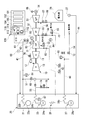
- the combined cycle plant of the present embodiment includes a gas turbine 10, an exhaust heat recovery boiler 20 generating steam by exhaust heat of combustion gas exhausted from the gas turbine 10, and an exhaust heat recovery boiler 20.
- the rated pressure of the high pressure steam turbine 31 is 12 MPa
- the rated pressure of the medium pressure steam turbine 32 is 4 MPa
- the rated pressure of the low pressure steam turbine 33 is 1 MPa.
- the gas turbine 10 includes a compressor 11 that compresses external air to generate compressed air, a combustor 12 that mixes compressed air with fuel gas and burns it to generate high-temperature combustion gas, and a turbine 13 driven by the combustion gas. And a fuel flow control valve 76 for adjusting the flow rate of fuel supplied to the combustor 12.
- a fuel line for supplying fuel from a fuel supply source to the combustor 12 is connected to the combustor 12 of the gas turbine 10.
- the fuel flow control valve 76 described above is provided in this fuel line.
- An exhaust port of the turbine 13 of the gas turbine 10 is connected to an exhaust heat recovery boiler 20.
- the compressor rotor of the compressor 11 and the turbine rotor of the turbine 13 are connected to each other on the same axis and integrally rotate as a gas turbine rotor.
- the gas turbine rotor, the turbine rotor of the high pressure steam turbine 31, the turbine rotor of the medium pressure steam turbine 32, the turbine rotor of the low pressure steam turbine 33, and the generator rotor of the generator 34 Are coaxially connected to each other and integrally rotate. Therefore, the combined cycle plant of the present embodiment is a single-shaft combined cycle plant.
- the exhaust heat recovery boiler 20 generates a high pressure steam generation unit (first steam generation unit) 21 that generates high pressure steam (first steam) to be supplied to the high pressure steam turbine 31, and medium pressure steam to be supplied to the medium pressure steam turbine 32.
- the medium pressure steam generation unit 23 to be generated, the low pressure steam generation unit 27 to be supplied to the low pressure steam turbine 33, and the reheating unit 26 to heat the steam exhausted from the high pressure steam turbine 31 are provided.
- the high pressure steam generating unit 21 includes a high pressure drum 22a that generates steam, and a high pressure superheater 22b that superheats the steam generated by the high pressure drum 22a.
- the medium pressure steam generation unit 23 includes an medium pressure drum 24 a that generates medium pressure steam, and an medium pressure superheater 24 b that superheats medium pressure steam generated by the medium pressure drum 24 a.
- the medium pressure drum 24a is provided with a medium pressure drum pressure gauge 87 that detects the pressure P5 in the medium pressure drum 24a.
- the low pressure steam generation unit 27 has a low pressure drum 28a that generates steam, and a low pressure superheater 28b that superheats the steam generated by the low pressure drum 28a.
- the high pressure superheater 22b of the exhaust heat recovery boiler 20 and the steam inlet of the high pressure steam turbine 31 are connected by a main steam line (first steam line) 41 for leading high pressure steam from the high pressure superheater 22b to the high pressure steam turbine 31 There is.
- the steam outlet of the high pressure steam turbine 31 and the steam inlet of the medium pressure steam turbine 32 pass the steam exhausted from the high pressure steam turbine 31 to the steam inlet of the medium pressure steam turbine 32 through the reheating part 26 of the exhaust heat recovery boiler 20. It is connected by the reheat steam line 42 leading.
- a pre-reheating steam line 42 a between the steam outlet of the high pressure steam turbine 31 and the reheating portion 26 in the reheating steam line 42 is a pre-reheating steam line 42 a, and between the reheating portion 26 and the steam inlet of the medium pressure steam turbine 32.
- the low pressure superheater 28 b of the exhaust heat recovery boiler 20 and the steam inlet of the low pressure steam turbine 33 are connected by a low pressure steam line 43 which leads low pressure steam to the low pressure steam turbine 33.
- the steam outlet of the medium pressure steam turbine 32 and the steam inlet of the low pressure steam turbine 33 are connected by a medium pressure turbine exhaust line 56.
- a condenser 36 is connected to the steam outlet of the low pressure steam turbine 33.
- a water supply line 44 for leading the condensed water to the exhaust heat recovery boiler 20 is connected to the condenser 36.
- the water supply pump 37 described above is provided in the water supply line 44.
- the medium pressure superheater 24 b of the exhaust heat recovery boiler 20 and the pre-reheat steam line 42 a are connected by a medium pressure steam line 55.
- the main steam line 41 and the pre-reheat steam line 42 a are connected by a high pressure turbine bypass line (first bypass line) 51.
- the pre-reheat steam line 42 a and the condenser 36 are connected by a ventilator line (second bypass line) 52.
- the connection position of the high pressure turbine bypass line 51 in the pre-reheat steam line 42 a is on the downstream side (reheat unit 26 side) than the connection position of the ventilator line 52.
- the connection position of the medium pressure steam line 55 in the pre-reheat steam line 42 a is on the downstream side (reheat unit 26 side) than the connection position of the high pressure turbine bypass line 51.
- the post-reheat steam line 42 b and the condenser 36 are connected by an intermediate pressure turbine bypass line 53, and the low pressure steam line 43 and the condenser 36 are connected by a low pressure turbine bypass line 54.
- a main steam stop valve 61, a main steam control valve 62, and an inflow steam pressure gauge 82 are provided in this order toward the downstream side.
- the high pressure steam pressure gauge 81 detects the pressure of the high pressure steam from the high pressure superheater 22 b and detects the pressure P 2 on the upstream side (high pressure steam generation unit 21 side) of the main steam stop valve 61.
- the inflow steam pressure gauge 82 detects the pressure of high-pressure steam, which is a pressure P1 downstream of the main steam control valve 62. That is, the inflow steam pressure gauge 82 detects the pressure P1 of the high pressure steam just before flowing into the high pressure steam turbine 31.
- the first stage stationary blade ring of the high pressure steam turbine 31 is provided with a thermometer 83 for detecting the temperature of the first stage stationary blade ring (vapor contact portion).
- the high pressure turbine bypass line 51 is provided with a high pressure turbine bypass valve 68 and a temperature reducer 69.
- a medium pressure drum pressure control valve 74 for adjusting the pressure in the medium pressure drum 24a, and a check valve for preventing the steam from the reheat steam line 42a from flowing into the medium pressure drum 24a. 75 are provided.
- a check valve 63 is provided on the downstream side of the connecting position with the ventilator line 52 (on the side of the reheating unit 26) in the pre-reheating steam line 42a.
- the check valve 63 prevents the steam flowing into the pre-reheat steam line 42 a through the high pressure turbine bypass line 51 and the medium pressure steam line 55 from flowing into the high pressure steam turbine 31.
- the ventilator line 52 is provided with a ventilator valve 71.
- the control valve 65 is provided in this order toward the downstream side.
- An intermediate pressure turbine bypass valve 72 is provided in the intermediate pressure turbine bypass line 53.
- a low pressure steam pressure gauge 85, a low pressure steam stop valve 66, and a low pressure steam control valve 67 are located downstream of the connection position of the low pressure steam line 43 with the low pressure turbine bypass line 54 (low pressure steam turbine 33). Are provided in this order towards.
- a low pressure turbine bypass valve 73 is provided in the low pressure turbine bypass line 54.
- the control device 100 includes a fuel flow rate controller 101 that controls the operation of the fuel flow rate control valve 76, a main steam stop valve controller 102 that controls the operation of the main steam stop valve 61, and a main steam
- the main steam control valve controller 103 that controls the operation of the control valve 62
- the high pressure turbine bypass valve controller 104 that controls the operation of the high pressure turbine bypass valve 68
- the ventilator valve controller 110 that controls the operation of the ventilator valve 71 And.
- the control device 100 includes the reheat steam stop valve 64, the reheat steam control valve 65, the low pressure steam stop valve 66, the low pressure steam control valve 67, the medium pressure turbine bypass valve 72, the low pressure turbine bypass valve 73, and the medium pressure.
- a controller or the like that controls the operation of the drum pressure control valve 74 is also included.
- the ventilator valve controller 110 determines whether the pressure P1 of the high pressure steam detected by the inflow steam pressure gauge 82 becomes a threshold value, and the determination unit 111 determines the pressure P1 of the high pressure steam by the threshold value. If it is judged that the value has been reached, the start mode of the exhaust heat recovery boiler 20 is recognized by the command output unit 112 which outputs a close command to the ventilator valve 71 and the temperature of the high pressure steam turbine 31 detected by the thermometer 83
- the activation mode recognition unit 113 has a threshold value change unit 114 that changes the threshold value in the determination unit 111 according to the activation mode recognized by the activation mode recognition unit 113.
- the start modes of the exhaust heat recovery boiler 20 include, for example, a hot mode which is a start from a state where the temperature of the high pressure steam turbine 31 is high and a cold mode which is a start from a state where the temperature of the high pressure steam turbine 31 is low. .
- the start mode recognition unit 113 recognizes that the hot mode is in the case where the temperature of the high pressure steam turbine 31 detected by the thermometer 83 is 400 ° C. or higher, for example.
- the start mode recognition unit 113 recognizes that the cold mode is established if the temperature of the high pressure steam turbine 31 detected by the thermometer 83 is less than 400 ° C., for example.
- control device 100 of the present embodiment is configured by a computer, and all processing of each part of the control device 100 is performed by using a storage device such as an external storage device such as a hard disk drive device or a memory and the like. And a CPU that executes a stored program.
- a storage device such as an external storage device such as a hard disk drive device or a memory and the like.
- a CPU that executes a stored program.
- the control device 100 When the control device 100 receives a start command from the outside, the control device 100 outputs a start command to a not-shown start device to start the start device.
- the start-up of the starter causes the compressor rotor and the turbine rotor of the gas turbine 10 to rotate. As the compressor rotor rotates, compressed air from the compressor 11 begins to be supplied to the combustor 12.
- the fuel flow controller 101 When the compressor rotor and the turbine rotor reach, for example, a predetermined rotational speed, the fuel flow controller 101 outputs an open command to the fuel flow control valve 76. As a result, the fuel from the fuel line is started to be supplied to the combustor 12 via the fuel flow control valve 76. The fuel burns in the compressed air supplied from the compressor 11 to the combustor 12. The combustion gas generated in the combustor 12 flows into the turbine 13 to rotate the turbine rotor.
- the fuel flow rate controller 101 In the process of starting the gas turbine 10, the fuel flow rate controller 101 outputs an open command indicating an opening degree in accordance with a predetermined pattern in which the fuel flow rate control valve 76 is gradually opened as time passes. For this reason, the flow rate of the fuel supplied to the combustor 12 also gradually increases, and as shown in FIG. 3, the rotational speed of the turbine rotor also gradually increases. When the turbine rotor reaches a predetermined rotational speed, the rotation assistance of the turbine rotor by the starter is stopped.
- the generator 34 is connected to the grid power line, and the rotational speeds of the turbine rotor and the generator 34 rotor are maintained at this rated rotational speed.
- the combustion gas having passed through the turbine 13 is sent to the exhaust heat recovery boiler 20 as exhaust gas.
- the steam generation units 21, 23, 27 of the exhaust heat recovery boiler 20 exchange heat between the exhaust gas flowing through the exhaust heat recovery boiler 20 and water to heat the water and convert it into steam.
- the high pressure steam generated by the high pressure steam generation unit 21 flows into the main steam line 41.
- the medium pressure steam generated in the medium pressure steam generation unit 23 flows into the medium pressure steam line 55.
- the low pressure steam generated in the low pressure steam generation unit 27 flows into the low pressure steam line 43.
- the high pressure turbine bypass valve 68, the intermediate pressure turbine bypass valve 72, the low pressure turbine bypass valve 73, and the intermediate pressure drum pressure control valve 74 are all closed.
- the ventilator valve 71 is in an open state before steam generation from the exhaust heat recovery boiler 20 starts.
- the low pressure turbine bypass valve 73 is controlled by the control device 100 so that the pressure P4 of the low pressure steam line 43 is maintained at, for example, 0.5 MPa lower than the rated pressure of 1 MPa of the low pressure steam turbine 33 in the process of starting the plant. Therefore, the low pressure turbine bypass valve 73 is closed until the pressure P4 of the low pressure steam detected by the low pressure steam pressure gauge 85 becomes 0.5 MPa.
- the low pressure turbine bypass valve 73 opens and the low pressure steam from the low pressure steam generation unit 27 becomes low pressure It will flow into the condenser 36 via the turbine bypass line 54.
- the control device 100 controls the medium pressure drum pressure control valve 74 such that the medium pressure drum 24a is maintained at a predetermined pressure, for example, a pressure somewhat higher than the rated pressure 4 MPa of the medium pressure steam turbine 32. Therefore, when the pressure in the medium pressure drum 24a becomes equal to or higher than the pressure to be maintained, the medium pressure drum pressure control valve 74 is opened, and the medium pressure steam generated in the medium pressure drum 24a is reheated via the medium pressure steam line 55. It will flow into the front steam line 42a.
- a predetermined pressure for example, a pressure somewhat higher than the rated pressure 4 MPa of the medium pressure steam turbine 32. Therefore, when the pressure in the medium pressure drum 24a becomes equal to or higher than the pressure to be maintained, the medium pressure drum pressure control valve 74 is opened, and the medium pressure steam generated in the medium pressure drum 24a is reheated via the medium pressure steam line 55. It will flow into the front steam line 42a.
- the medium pressure turbine bypass valve 72 is controlled by the control device 100 so that the pressure P3 of the steam line 42b after reheating is maintained at 2 MPa, which is lower than the rated pressure 4 MPa of the medium pressure steam turbine 32, for example, in the process of starting the plant. Ru. Therefore, the intermediate pressure turbine bypass valve 72 is closed until the pressure P3 of the reheated (medium pressure) steam detected by the reheated steam pressure gauge 84 becomes 2 MPa. If the amount of medium pressure steam generated by the medium pressure steam generation unit 23 and the flow rate of steam etc.
- the high pressure turbine bypass valve 68 is a high pressure turbine bypass valve controller of the control device 100 such that the pressure P2 of the main steam line 41 is maintained at 5 MPa, for example, lower than the rated pressure 12 MPa of the high pressure steam turbine 31 in the process of starting the plant. It is controlled by 104. Therefore, the high pressure turbine bypass valve 68 is closed as shown in FIG. 3 until the pressure P2 of the high pressure steam detected by the high pressure steam pressure gauge 81 becomes 5 MPa.
- the high pressure turbine bypass valve 68 opens and the high pressure steam from the high pressure steam generation unit 21 is the high pressure turbine bypass It will flow into the reheat steam line 42 via the line 51.
- the control device 100 recognizes that the supply start condition of the steam to be supplied to each of the steam turbines 31, 32, 33 is satisfied in the process of starting the plant, the steam stop valves 61, 64 of the respective steam turbines 31, 32, 33. , 66 and the steam control valves 62, 65, 67.
- the steam supply start condition is, for example, that the temperature detected by the thermometer 83 provided in the high pressure steam turbine 31 becomes a predetermined temperature.
- the steam control valves 62, 65, 67 are gradually opened in accordance with a predetermined opening degree pattern.
- steam starts to be supplied to the steam turbines 31, 32, 33, and the steam turbine output (the total output of the high pressure steam turbine 31, the medium pressure steam turbine 32, and the low pressure steam turbine 33) It will increase gradually.
- the supply start condition of the steam is such that the temperature detected by the thermometer 83 provided in the high pressure steam turbine 31 becomes a predetermined temperature.
- the steam supply start condition is detected by the thermometer provided in the medium pressure steam turbine 32.
- the set temperature may be a predetermined temperature.
- the controller 100 gradually closes the low pressure turbine bypass valve 73 to maintain the pressure P4 of the low pressure steam line 43.
- the controller 100 gradually closes the intermediate pressure turbine bypass valve 72 to maintain the pressure P3 of the steam line 42b after reheating.
- the high pressure turbine bypass valve controller 104 gradually closes the high pressure turbine bypass valve 68 as shown in FIG. 3 in order to maintain the pressure P2 of the main steam line 41.
- the control device 100 After recognizing that the switching conditions for the steam supplied to each of the steam turbines 31, 32, and 33 are satisfied, the control device 100 subsequently changes the maintenance pressure of the steam line for supplying steam to each of the steam turbines 31, 32, and 33. Do. Specifically, the control device 100 controls the low pressure turbine bypass valve 73 such that the pressure P4 of the low pressure steam line 43 is maintained at 1.1 MPa, which is slightly higher than the rated pressure of 1 MPa of the low pressure steam turbine 33, for example. Therefore, once the switching condition is satisfied, the low pressure turbine bypass valve 73 does not open unless the pressure P4 of the low pressure steam line 43 becomes 1.1 MPa or more.
- the control device 100 recognizes that the switching condition is satisfied, the pressure P3 of the steam line 42b after reheating is maintained at 4.1 MPa, which is slightly higher than the rated pressure 4 MPa of the medium pressure steam turbine 32, for example. , Control the intermediate pressure turbine bypass valve 72. For this reason, once the switching conditions are satisfied, the intermediate pressure turbine bypass valve 72 does not open unless the pressure P3 of the steam line 42b after reheating becomes 4.1 MPa or more.
- the high pressure turbine bypass valve controller 104 of the control device 100 recognizes that the switching condition is satisfied, the pressure P2 of the main steam line 41 is slightly higher than the rated pressure 12MPa of the high pressure steam turbine 31, for example 12.1MPa. Control the high pressure turbine bypass valve 68 so that Therefore, once the switching condition is satisfied, the high pressure turbine bypass valve 68 is not opened unless the pressure P2 of the main steam line 41 becomes 12.1 MPa or more.
- the ventilator valve 71 is opened and the steam exhausted from the high pressure steam turbine 31 is condensed through the ventilator line 52. It is sent to 36.
- the pressure difference between the pressure at the steam inlet of the high pressure steam turbine 31 and the pressure at the steam outlet increases, and the workload of steam in the high pressure steam turbine 31 increases. The temperature rise of the steam exhausted from 31 can be suppressed.
- the ventilator valve 71 is closed when it is determined by the determination unit 111 of the ventilator valve controller 110 that the flow rate of the high pressure steam supplied to the high pressure steam turbine 31 has become a specified flow rate. Specifically, the determination unit 111 of the ventilator valve controller 110 determines whether the flow rate of the high pressure steam supplied to the high pressure steam turbine 31 has become a specified flow rate based on the pressure P1 detected by the inflow steam pressure gauge 82 (Judgment process). The flow rate of the high pressure steam supplied to the high pressure steam turbine 31 and the pressure P1 detected by the inflow steam pressure gauge 82 have a positive correlation.
- the determination unit 111 detects the pressure by the inflow steam pressure gauge 82 by setting the pressure corresponding to the prescribed flow rate of the flow of high pressure steam as the threshold value at the pressure P1 detected by the inflow steam pressure gauge 82. Whether or not the flow rate of high-pressure steam has reached a specified flow rate can be determined depending on whether or not the pressure P1 reached a threshold value.
- the threshold value is changed by the threshold value changing unit 114 of the ventilator valve controller 110 according to the start mode of the exhaust heat recovery boiler 20.
- the start mode recognition unit 113 If the temperature of the high pressure steam turbine 31 detected by the thermometer 83 is, for example, less than 400 ° C., it is recognized that it is in the cold mode (start mode recognition step).
- the threshold change unit 114 sets the threshold to, for example, 4 MPa. Further, when the start mode recognized by the start mode recognition unit 113 is the cold mode, the threshold change unit 114 sets the threshold to, for example, 2 MPa (threshold change step).
- the ventilator valve controller 110 determines that the flow rate of high pressure steam flowing into the high pressure steam turbine 31 has become a prescribed flow rate, that is, the pressure P1 detected by the inflow steam pressure gauge 82 has become a threshold.
- the command output unit 112 outputs a close command to the ventilator valve 71 (command output process).
- the closing command also includes the content of setting the opening degree change rate, which is the opening degree change amount per unit time of the ventilator valve 71, to a predetermined opening degree change rate.
- the ventilator valve 71 is gradually closed at a predetermined rate of change of opening upon receiving the closing command.
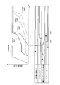
- FIG. 3 shows a timing chart when the startup mode is the hot mode
- FIG. 4 shows a timing chart when the startup mode is the cold mode.
- the timing t1 at which the output of the gas turbine 10 starts to be obtained is basically the same in the hot mode and the cold mode. However, the time until the output of the gas turbine 10 reaches the rated output is longer in the cold mode than in the hot mode.
- the conditions for opening the steam stop valves 61, 64, 66 and the steam control valves 62, 65, 67 of the steam turbines 31, 32, 33 that is, the supply start conditions of the steam supplied to the steam turbines 31, 32, 33, The same applies to the hot mode and the cold mode.
- the temperatures of the water staying in the exhaust heat recovery boiler 20 and the metal temperatures of the steam turbines 31, 32, 33 are lower than those in the hot mode.
- the timing at which the supply start condition of the steam supplied to is satisfied is later than the timing in the hot mode.
- the timing at which the steam stop valves 61, 64, 66 and the steam control valves 62, 65, 67 of the steam turbines 31, 32, 33 open, and the outputs of the steam turbines 31, 32, 33 are obtained.
- the timing t2 (c) at which the signal is started is later than the timing t2 (h) in the hot mode.
- the opening degree change rate which is the opening degree change amount per unit time of each of the steam control valves 62, 65, 67 of the steam turbines 31, 32, 33 is smaller in the cold mode than in the hot mode.
- the steam control valves 62, 65, 67 of the steam turbines 31, 32, 33 open more slowly in the cold mode than in the hot mode. Therefore, the outputs of the steam turbines 31, 32, and 33 increase more slowly in the cold mode than in the hot mode.
- the pressure to be maintained in each steam line is the same in the hot mode and the cold mode. That is, in the start-up process of the plant, the high-pressure turbine bypass valve 68 is controlled such that the pressure P2 of the main steam line 41 is maintained at 5 MPa in the hot mode and the cold mode. Furthermore, the medium pressure turbine bypass valve 72 is controlled so that the pressure P3 of the steam line 42b is maintained at 2 MPa after reheating, and the low pressure turbine bypass valve so that the pressure P4 of the low pressure steam line 43 is maintained at 0.5 MPa. 73 is controlled.
- the startup mode recognition unit 113 of the ventilator valve controller 110 recognizes that the startup mode is the hot mode.
- the threshold value changing unit 114 sets the threshold to, for example, 4 MPa. Therefore, in the startup process in the hot mode, when the pressure P1 detected by the inflow steam pressure gauge 82 becomes 4 MPa, the determination unit 111 determines that the flow rate of the high pressure steam flowing into the high pressure steam turbine 31 becomes the prescribed flow rate. .
- the command output unit 112 of the ventilator valve controller 110 When the determination unit 111 determines that the flow rate has reached the specified flow rate, the command output unit 112 of the ventilator valve controller 110 outputs a closing command to the ventilator valve 71. As shown in FIG. 3, the ventilator valve 71 is closed at a predetermined opening change rate (t3 (h)) when receiving this closing command.
- the startup mode recognition unit 113 of the ventilator valve controller 110 recognizes that the startup mode is the cold mode.
- the threshold change unit 114 sets the threshold to, for example, 2 MPa. Therefore, in the startup process in the cold mode, when the pressure P1 detected by the inflow steam pressure gauge 82 becomes 2 MPa, the determination unit 111 determines that the flow rate of the high pressure steam flowing into the high pressure steam turbine 31 becomes the prescribed flow rate. .
- the command output unit 112 of the ventilator valve controller 110 outputs a closing command to the ventilator valve 71 as described above. As shown in FIG. 4, the ventilator valve 71 is closed at a predetermined opening change rate (t3 (c)) when the closing command is received.
- the generation amount of high pressure steam in the high pressure steam generation unit 21 immediately before the ventilator valve 71 starts closing in the case of the hot mode is 200 t / h.
- the flow rate of the high pressure steam flowing into the steam line 42 b after reheating through the high pressure turbine bypass valve 68 and the reheat part 26 of the exhaust heat recovery boiler 20 is 100 t / h. It is assumed that the flow rate of high pressure steam flowing into the condenser 36 via the condenser 36 is 100 t / h.
- the flow rate of the steam flowing into the steam line 42b after reheating changes from 100 t / h to 200 t / h before and after closing the ventilator valve 71, ignoring the medium pressure steam generated in the medium pressure steam generation unit 23. .
- the generation amount of high pressure steam in the high pressure steam generation unit 21 immediately before the ventilator valve 71 starts closing in the cold mode is 150 t / h.
- the flow rate of the high pressure steam flowing into the steam line 42 b after reheating through the high pressure turbine bypass valve 68 and the reheat part 26 of the exhaust heat recovery boiler 20 is 100 t / h. It is assumed that the flow rate of high pressure steam flowing into the condenser 36 via the condenser 36 is 50 t / h.
- the flow rate of the steam flowing into the steam line 42b after reheating is 100 t / h to 150 t / h before and after the ventilator valve 71 is closed, ignoring the medium pressure steam generated in the medium pressure steam generation unit 23 as described above. Change to h.
- the hot mode The flow rate of high pressure steam flowing into the condenser 36 via the ventilator valve 71 immediately before the ventilator valve 71 starts to close is 100 t / h.
- the timing t3 (cc) at which the ventilator valve 71 is closed in the comparative example is later than the timing t3 (c) at which the ventilator valve 71 is closed in the present embodiment.
- the rate of change in the flow rate of steam flowing through the steam line 42b after reheating before and after closing the ventilator valve 71 is larger than in the cold mode and the hot mode of the present embodiment. . Therefore, in the case of the cold mode in the comparative example, the control system related to the reheat steam line 42, more specifically, the control system that controls based on the state quantity of steam passing through the reheat steam line 42b is unstable. The chances of becoming
- the threshold for determining whether the flow rate of the high pressure steam flowing into the high pressure steam turbine 31 has reached the specified flow rate is 4 MPa in the hot mode (specified flow rate Is 100 t / h), and 2 MPa (specific flow rate is 50 t / h) in the cold mode.
- the rate of change of the flow rate of steam flowing through the steam line 42b after reheating before and after closing the ventilator valve 71 can be made relatively small as in the case of the hot mode.
- the control system relating to the reheat steam line 42 can be prevented from becoming unstable.
- the start-up process of the plant there is a positive correlation between the temperature of the high pressure steam from the high pressure steam generation unit 21 and the amount of the high pressure steam generated. That is, in the start-up process of the plant, when the temperature of the high pressure steam from the high pressure steam generating unit 21 increases, the amount of the high pressure steam generated increases, and when the temperature of the high pressure steam from the high pressure steam generating unit 21 decreases, the high pressure The amount of steam generated decreases. Further, in the process of starting the plant, when the temperature of the high pressure steam rises, the flow rate of the high pressure steam supplied to the high pressure steam turbine 31 increases.
- the temperature of the high pressure steam and the flow rate of the high pressure steam supplied to the high pressure steam turbine 31 have a positive correlation.
- the inventor pays attention to the point concerned, and in the present embodiment, the threshold value for determining whether or not the determination flow rate has reached the specified flow rate is positively correlated with the temperature of the high pressure steam. It has changed. For this reason, in the present embodiment, when the generation amount of high pressure steam from the high pressure steam generation unit 21 is small, the specified flow rate becomes small, and the flow rate change rate of steam flowing in the steam line 42b after reheating before and after closing of the ventilator valve 71 Can be made smaller.
- the start mode of the exhaust heat recovery boiler 20 is recognized according to the temperature detected by the thermometer 83 provided in the high pressure steam turbine 31. However, when the start of the gas turbine 10 this time is within a predetermined time from the previous stop of the gas turbine 10, it is recognized that the start mode of the exhaust heat recovery boiler 20 is the hot mode, and the predetermined time When it exceeds, the start-up mode of the exhaust heat recovery boiler 20 may be recognized as the cold mode.
- the threshold value is changed according to the start mode of the exhaust heat recovery boiler 20.
- the main steam line 41 may be provided with a thermometer 89, and the threshold may be changed according to the temperature of high pressure steam detected by the thermometer 89.
- the threshold is increased when the temperature of the high pressure steam is high, and the threshold is decreased when the temperature of the high pressure steam is low. That is, in this case, the ventilator valve controller 110 does not recognize the start mode of the exhaust heat recovery boiler 20.
- the high pressure steam turbine 31 has a hot mode of 450 ° C. or more, the high pressure steam turbine 31 has a temperature of less than 450 ° C., a worm mode of 350 ° C. or more, and the temperature of the high pressure steam turbine 31 There is a cold mode of less than 350 ° C.
- 4 MPa may be set as the threshold value in the hot mode, 3 MPa as the threshold value in the warm mode, and 2 MPa as the threshold value in the cold mode.
- the specific pressure of the high pressure steam flowing into the high pressure steam turbine 31 is set as the threshold value for determining whether or not the determination unit 111 has reached the specified flow rate.
- a flow meter for detecting the flow rate of high pressure steam flowing into high pressure steam turbine 31, and a threshold value for determining whether or not determination unit 111 has reached a specified flow rate for a specific flow rate detected by this flow meter is provided.
- the closing command for the ventilator valve 71 includes the content that sets the opening degree change rate, which is the opening degree change amount per unit time of the ventilator valve 71, to a predetermined opening degree change rate. Therefore, the opening change rate may also be changed with a positive correlation with the temperature of the high pressure steam. That is, when the temperature of the high pressure steam is high, the opening change rate may be increased, and when the temperature of the high pressure steam is low, the opening change rate may be decreased.
- the combined cycle plant of the present embodiment includes three steam turbines of a high pressure steam turbine 31, an intermediate pressure steam turbine 32, and a low pressure steam turbine 33.
- a steam corresponding to the low pressure steam turbine 33 according to the present embodiment includes the first steam turbine corresponding to the high pressure steam turbine 31 according to the present embodiment and the second steam turbine corresponding to the medium pressure steam turbine 32 according to the present embodiment. Even if the turbine is not provided, the present invention can be applied.
Landscapes
- Engineering & Computer Science (AREA)
- Chemical & Material Sciences (AREA)
- Combustion & Propulsion (AREA)
- Mechanical Engineering (AREA)
- General Engineering & Computer Science (AREA)
- Control Of Turbines (AREA)
- Engine Equipment That Uses Special Cycles (AREA)
Priority Applications (5)
| Application Number | Priority Date | Filing Date | Title |
|---|---|---|---|
| KR1020177024497A KR20170103991A (ko) | 2014-03-20 | 2015-03-03 | 콤바인드사이클플랜트, 그 제어방법 및 그 제어장치 |
| CN201580007854.5A CN105980668B (zh) | 2014-03-20 | 2015-03-03 | 联合循环机组、其控制方法及其控制装置 |
| KR1020167022110A KR102051279B1 (ko) | 2014-03-20 | 2015-03-03 | 콤바인드사이클플랜트, 그 제어방법 및 그 제어장치 |
| DE112015001364.4T DE112015001364B4 (de) | 2014-03-20 | 2015-03-03 | Kombianlage, Verfahren zur Steuerung derselben und Vorrichtung für die Steuerung derselben |
| US15/116,079 US10287921B2 (en) | 2014-03-20 | 2015-03-03 | Combined cycle plant, method for controlling same, and device for controlling same |
Applications Claiming Priority (2)
| Application Number | Priority Date | Filing Date | Title |
|---|---|---|---|
| JP2014058967A JP6264128B2 (ja) | 2014-03-20 | 2014-03-20 | コンバインドサイクルプラント、その制御方法、及びその制御装置 |
| JP2014-058967 | 2014-03-20 |
Publications (1)
| Publication Number | Publication Date |
|---|---|
| WO2015141458A1 true WO2015141458A1 (ja) | 2015-09-24 |
Family
ID=54144433
Family Applications (1)
| Application Number | Title | Priority Date | Filing Date |
|---|---|---|---|
| PCT/JP2015/056182 Ceased WO2015141458A1 (ja) | 2014-03-20 | 2015-03-03 | コンバインドサイクルプラント、その制御方法、及びその制御装置 |
Country Status (6)
| Country | Link |
|---|---|
| US (1) | US10287921B2 (https=) |
| JP (1) | JP6264128B2 (https=) |
| KR (2) | KR20170103991A (https=) |
| CN (1) | CN105980668B (https=) |
| DE (1) | DE112015001364B4 (https=) |
| WO (1) | WO2015141458A1 (https=) |
Cited By (1)
| Publication number | Priority date | Publication date | Assignee | Title |
|---|---|---|---|---|
| JP2018080672A (ja) * | 2016-11-18 | 2018-05-24 | 株式会社東芝 | タービン制御装置 |
Families Citing this family (9)
| Publication number | Priority date | Publication date | Assignee | Title |
|---|---|---|---|---|
| JP6845675B2 (ja) * | 2016-12-08 | 2021-03-24 | 川崎重工業株式会社 | 原料ガス液化装置及びその制御方法 |
| KR20190016734A (ko) * | 2017-08-09 | 2019-02-19 | 두산중공업 주식회사 | 발전 플랜트 및 그 제어방법 |
| CN110821587A (zh) * | 2019-11-22 | 2020-02-21 | 润电能源科学技术有限公司 | 一种切缸方法、装置及设备 |
| CN113202570B (zh) * | 2021-04-20 | 2023-04-18 | 华能苏州热电有限责任公司 | 一种燃气蒸汽联合循环机组冷态启动方法及设备 |
| CN114941552B (zh) * | 2022-05-13 | 2023-05-23 | 华电电力科学研究院有限公司 | 一种基于大型超临界再热型双抽背压机组停机不停炉供热快速切换控制方法 |
| JP7735234B2 (ja) * | 2022-08-18 | 2025-09-08 | 株式会社東芝 | コンバインドサイクル発電設備 |
| KR102728839B1 (ko) * | 2022-11-29 | 2024-11-08 | 두산에너빌리티 주식회사 | 복합발전 시스템 및 그 제어방법 |
| DE102023203690A1 (de) * | 2023-04-21 | 2024-10-24 | Siemens Energy Global GmbH & Co. KG | Verfahren zum Anwärmen von Einströmventilen von Turbinen und Schnellschlussventil zum Durchführen des Verfahrens |
| WO2024226063A1 (en) * | 2023-04-28 | 2024-10-31 | General Electric Technology Gmbh | Combined cycle power generation systems |
Citations (6)
| Publication number | Priority date | Publication date | Assignee | Title |
|---|---|---|---|---|
| JPS6198908A (ja) * | 1984-10-19 | 1986-05-17 | Hitachi Ltd | 蒸気タ−ビン装置 |
| JPH0211807A (ja) * | 1988-06-29 | 1990-01-16 | Hitachi Ltd | 低圧タービンバイパス制御装置 |
| JPH06221112A (ja) * | 1993-01-25 | 1994-08-09 | Toshiba Corp | タービンバイパス弁制御装置 |
| JP2013015044A (ja) * | 2011-07-01 | 2013-01-24 | Mitsubishi Heavy Ind Ltd | コンバインドサイクル発電プラント |
| JP2013015043A (ja) * | 2011-07-01 | 2013-01-24 | Mitsubishi Heavy Ind Ltd | コンバインドサイクル発電プラント及びその運転方法 |
| JP2013104411A (ja) * | 2011-11-16 | 2013-05-30 | Mitsubishi Heavy Ind Ltd | 複合発電プラントの給電可能時間演算システム |
Family Cites Families (11)
| Publication number | Priority date | Publication date | Assignee | Title |
|---|---|---|---|---|
| US4184324A (en) * | 1975-04-02 | 1980-01-22 | Westinghouse Electric Corp. | Combined cycle electric power plant with coordinated plural feedback turbine control |
| JPS60228711A (ja) * | 1984-04-25 | 1985-11-14 | Hitachi Ltd | コンバインドサイクル発電プラントのタ−ビンバイパス制御装置 |
| JPS61237802A (ja) * | 1985-04-12 | 1986-10-23 | Hitachi Ltd | 蒸気タ−ビンの暖機方法 |
| JPH07166814A (ja) * | 1993-12-14 | 1995-06-27 | Toshiba Corp | 一軸コンバインドサイクル発電プラントの起動方法 |
| JP2003020905A (ja) | 2001-07-06 | 2003-01-24 | Mitsubishi Heavy Ind Ltd | 再熱発電プラントの運転装置および運転方法 |
| JP4503995B2 (ja) | 2003-12-02 | 2010-07-14 | 株式会社東芝 | 再熱蒸気タービンプラントおよびその運転方法 |
| JP2005344528A (ja) * | 2004-05-31 | 2005-12-15 | Toshiba Corp | コンバインドサイクル発電プラントおよびその起動運転方法 |
| JP4657057B2 (ja) | 2005-08-12 | 2011-03-23 | 株式会社日立製作所 | 再熱型蒸気タービンプラント |
| US7987675B2 (en) * | 2008-10-30 | 2011-08-02 | General Electric Company | Provision for rapid warming of steam piping of a power plant |
| US20100242430A1 (en) * | 2009-03-31 | 2010-09-30 | General Electric Company | Combined cycle power plant including a heat recovery steam generator |
| CN103452611B (zh) * | 2013-09-05 | 2015-04-22 | 上海电气电站设备有限公司 | 一种联合循环的热电联供系统 |
-
2014
- 2014-03-20 JP JP2014058967A patent/JP6264128B2/ja active Active
-
2015
- 2015-03-03 WO PCT/JP2015/056182 patent/WO2015141458A1/ja not_active Ceased
- 2015-03-03 US US15/116,079 patent/US10287921B2/en active Active
- 2015-03-03 KR KR1020177024497A patent/KR20170103991A/ko not_active Withdrawn
- 2015-03-03 CN CN201580007854.5A patent/CN105980668B/zh active Active
- 2015-03-03 DE DE112015001364.4T patent/DE112015001364B4/de active Active
- 2015-03-03 KR KR1020167022110A patent/KR102051279B1/ko active Active
Patent Citations (6)
| Publication number | Priority date | Publication date | Assignee | Title |
|---|---|---|---|---|
| JPS6198908A (ja) * | 1984-10-19 | 1986-05-17 | Hitachi Ltd | 蒸気タ−ビン装置 |
| JPH0211807A (ja) * | 1988-06-29 | 1990-01-16 | Hitachi Ltd | 低圧タービンバイパス制御装置 |
| JPH06221112A (ja) * | 1993-01-25 | 1994-08-09 | Toshiba Corp | タービンバイパス弁制御装置 |
| JP2013015044A (ja) * | 2011-07-01 | 2013-01-24 | Mitsubishi Heavy Ind Ltd | コンバインドサイクル発電プラント |
| JP2013015043A (ja) * | 2011-07-01 | 2013-01-24 | Mitsubishi Heavy Ind Ltd | コンバインドサイクル発電プラント及びその運転方法 |
| JP2013104411A (ja) * | 2011-11-16 | 2013-05-30 | Mitsubishi Heavy Ind Ltd | 複合発電プラントの給電可能時間演算システム |
Cited By (1)
| Publication number | Priority date | Publication date | Assignee | Title |
|---|---|---|---|---|
| JP2018080672A (ja) * | 2016-11-18 | 2018-05-24 | 株式会社東芝 | タービン制御装置 |
Also Published As
| Publication number | Publication date |
|---|---|
| DE112015001364T5 (de) | 2016-12-01 |
| JP2015183536A (ja) | 2015-10-22 |
| US20170152762A1 (en) | 2017-06-01 |
| US10287921B2 (en) | 2019-05-14 |
| CN105980668A (zh) | 2016-09-28 |
| KR102051279B1 (ko) | 2019-12-03 |
| DE112015001364B4 (de) | 2018-10-25 |
| JP6264128B2 (ja) | 2018-01-24 |
| CN105980668B (zh) | 2018-09-25 |
| KR20160107312A (ko) | 2016-09-13 |
| KR20170103991A (ko) | 2017-09-13 |
Similar Documents
| Publication | Publication Date | Title |
|---|---|---|
| JP6264128B2 (ja) | コンバインドサイクルプラント、その制御方法、及びその制御装置 | |
| JP5221443B2 (ja) | 一軸型複合サイクル発電プラントの起動方法および一軸型複合サイクル発電プラント | |
| US9353650B2 (en) | Steam turbine plant and driving method thereof, including superheater, reheater, high-pressure turbine, intermediate-pressure turbine, low-pressure turbine, condenser, high-pressure turbine bypass pipe, low-pressure turbine bypass pipe, and branch pipe | |
| JP6368611B2 (ja) | ガスタービン、コンバインドサイクルプラント、ガスタービンの起動方法 | |
| JP6375585B2 (ja) | コンバインドサイクルプラント、その制御方法、及びその制御装置 | |
| CN108868909A (zh) | 一种双机回热小汽轮机启动模式 | |
| JP2012167571A (ja) | 一軸型複合サイクル発電プラントおよびその運転方法 | |
| WO2016194742A1 (ja) | コンバインドサイクルプラント、その制御装置及び起動方法 | |
| JP2015183536A5 (https=) | ||
| JP6071421B2 (ja) | コンバインドサイクルプラント、及びその停止方法、及びその制御装置 | |
| JP5694112B2 (ja) | 一軸型複合サイクル発電プラント及びその運転方法 | |
| JP6231228B2 (ja) | 複合サイクルガスタービンプラント | |
| JP5050013B2 (ja) | 複合発電プラント及びその制御方法 | |
| JP5734117B2 (ja) | コンバインドサイクル発電プラント及びその運転方法 | |
| WO2020255719A1 (ja) | 発電プラント | |
| WO2014033837A1 (ja) | 排熱回収ボイラ、排熱回収ボイラの制御方法、及びこれを用いたコンバインドサイクル発電プラント | |
| JP6877216B2 (ja) | 発電システム | |
| JP2003254011A (ja) | 多軸型コンバインドサイクル発電プラントの運転方法 | |
| WO2015052810A1 (ja) | 太陽熱タービンシステム、そのシステム制御装置および方法 | |
| JP5289068B2 (ja) | 蒸気タービン発電プラント | |
| JP2025010976A (ja) | プラント制御装置、プラント制御方法、および発電プラント | |
| JP7153498B2 (ja) | コンバインドサイクル発電プラント | |
| JP6625848B2 (ja) | 蒸気加減弁制御装置、発電プラントおよび蒸気加減弁制御方法 | |
| JP2008075526A (ja) | 低圧蒸気タービンシステムおよび制御方法 | |
| JP6600572B2 (ja) | プラント制御装置およびプラント制御方法 |
Legal Events
| Date | Code | Title | Description |
|---|---|---|---|
| 121 | Ep: the epo has been informed by wipo that ep was designated in this application |
Ref document number: 15765753 Country of ref document: EP Kind code of ref document: A1 |
|
| WWE | Wipo information: entry into national phase |
Ref document number: 15116079 Country of ref document: US |
|
| ENP | Entry into the national phase |
Ref document number: 20167022110 Country of ref document: KR Kind code of ref document: A |
|
| WWE | Wipo information: entry into national phase |
Ref document number: 112015001364 Country of ref document: DE |
|
| 122 | Ep: pct application non-entry in european phase |
Ref document number: 15765753 Country of ref document: EP Kind code of ref document: A1 |