WO2015141011A1 - クロッピング装置、クロッピング方法、および、プログラム - Google Patents
クロッピング装置、クロッピング方法、および、プログラム Download PDFInfo
- Publication number
- WO2015141011A1 WO2015141011A1 PCT/JP2014/057914 JP2014057914W WO2015141011A1 WO 2015141011 A1 WO2015141011 A1 WO 2015141011A1 JP 2014057914 W JP2014057914 W JP 2014057914W WO 2015141011 A1 WO2015141011 A1 WO 2015141011A1
- Authority
- WO
- WIPO (PCT)
- Prior art keywords
- depth
- document
- color
- information
- cropping
- Prior art date
- Legal status (The legal status is an assumption and is not a legal conclusion. Google has not performed a legal analysis and makes no representation as to the accuracy of the status listed.)
- Ceased
Links
Images








Classifications
-
- G—PHYSICS
- G06—COMPUTING OR CALCULATING; COUNTING
- G06T—IMAGE DATA PROCESSING OR GENERATION, IN GENERAL
- G06T3/00—Geometric image transformations in the plane of the image
- G06T3/06—Topological mapping of higher dimensional structures onto lower dimensional surfaces
-
- H—ELECTRICITY
- H04—ELECTRIC COMMUNICATION TECHNIQUE
- H04N—PICTORIAL COMMUNICATION, e.g. TELEVISION
- H04N1/00—Scanning, transmission or reproduction of documents or the like, e.g. facsimile transmission; Details thereof
- H04N1/00795—Reading arrangements
- H04N1/00827—Arrangements for reading an image from an unusual original, e.g. 3-dimensional objects
-
- H—ELECTRICITY
- H04—ELECTRIC COMMUNICATION TECHNIQUE
- H04N—PICTORIAL COMMUNICATION, e.g. TELEVISION
- H04N1/00—Scanning, transmission or reproduction of documents or the like, e.g. facsimile transmission; Details thereof
- H04N1/387—Composing, repositioning or otherwise geometrically modifying originals
-
- H—ELECTRICITY
- H04—ELECTRIC COMMUNICATION TECHNIQUE
- H04N—PICTORIAL COMMUNICATION, e.g. TELEVISION
- H04N2201/00—Indexing scheme relating to scanning, transmission or reproduction of documents or the like, and to details thereof
- H04N2201/04—Scanning arrangements
- H04N2201/0402—Arrangements not specific to a particular one of the scanning methods covered by groups H04N1/04 - H04N1/207
- H04N2201/0434—Arrangements not specific to a particular one of the scanning methods covered by groups H04N1/04 - H04N1/207 specially adapted for scanning pages of a book
Definitions
- the present invention relates to a cropping device, a cropping method, and a program.
- JP 2013-26830 A Japanese Patent No. 4623898
- the conventional cropping method has a problem that the original document area to be cropped cannot be accurately determined, and the accuracy is low, such as when it is difficult to extract the edge because the original plate and the original are the same color.
- the present invention has been made in view of the above-described problems.
- a cropping apparatus and a cropping method capable of performing accurate cropping even when the colors of the document table and the document are the same and it is difficult to extract an edge. And to provide a program.
- a cropping device determines a document area based on color and depth in a three-dimensional information acquisition unit that acquires three-dimensional information of a document, and the three-dimensional information, Crop processing means for performing crop processing on the document area.
- the cropping method includes a three-dimensional information acquisition step for acquiring three-dimensional information of a document, and a crop processing step for performing crop processing by determining the document region based on color and depth in the three-dimensional information. And including.
- a program according to the present invention includes a three-dimensional information acquisition step for acquiring three-dimensional information of a document, a crop processing step for determining the document region based on color and depth in the three-dimensional information, and performing a crop processing. , Execute on the computer.
- the computer-readable recording medium records the program according to the present invention described above.
- the cropping can be accurately performed even when the colors of the document table and the document are the same and it is difficult to extract the edge.
- FIG. 1 is a hardware configuration diagram illustrating an example of the information processing apparatus 100.
- FIG. 2 is a functional block diagram illustrating an example of the information processing apparatus 100.
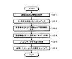
- FIG. 3 is a flowchart illustrating an example of overall processing in the information processing apparatus 100 when the positional relationship from the image reading apparatus 12 to the document table is fixed.
- FIG. 4 is a flowchart illustrating an example of overall processing in the information processing apparatus 100 when the positional relationship from the image reading apparatus 12 to the document table is variable.
- FIG. 5 is a diagram schematically showing the relationship between a document and a document table on which the document is placed.
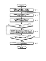
- FIG. 6 is a flowchart illustrating an example of the cropping process in the information processing apparatus 100 according to the present embodiment.
- FIG. 1 is a hardware configuration diagram illustrating an example of the information processing apparatus 100.
- FIG. 2 is a functional block diagram illustrating an example of the information processing apparatus 100.
- FIG. 3 is a flowchart illustrating an example of overall processing in the information processing
- FIG. 7 is an output conceptual diagram of the cropping process in FIG.
- FIG. 8 is a flowchart illustrating another example of the cropping process in the information processing apparatus 100 according to the present embodiment.
- FIG. 9 is an output conceptual diagram of the cropping process in FIG.
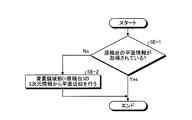
- FIG. 10 is a flowchart illustrating an example of document table depth estimation processing in the information processing apparatus 100 when the positional relationship from the image reading device 12 to the document table is unknown.
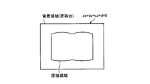
- FIG. 11 is a diagram schematically showing a document placed on a document table.
- FIG. 12 is a flowchart illustrating an example of mesh division processing in the information processing apparatus 100.
- FIG. 13 is a diagram schematically showing how the document area is divided into meshes.
- FIG. 14 is a diagram schematically showing how the document area is divided into meshes.
- FIG. 13 is a diagram schematically showing how the document area is divided into meshes.
- FIG. 15 is a diagram schematically illustrating the result of the final mesh division.
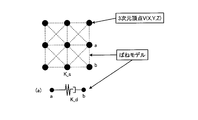
- FIG. 16 is a diagram schematically showing a spring model applied in the present embodiment.
- FIG. 17 is a flowchart illustrating an example of decompression processing in the information processing apparatus 100.
- FIG. 18 is a diagram showing an old mesh set before expansion.
- FIG. 19 is a diagram showing a new mesh set after expansion.
- FIG. 20 is a flowchart illustrating an example of mapping processing in the information processing apparatus 100.
- FIG. 21 is a diagram schematically illustrating a mapping process between a mesh set and an RGB image.
- the reading target may be described as a manuscript such as a magazine.
- the reading target is not limited to this.
- Newspaper, a medium bound with staples, a stack of single sheets, and the like are read. Also good.
- FIG. 1 is a hardware configuration diagram illustrating an example of the information processing apparatus 100.
- the present embodiment includes an information processing apparatus 100 that executes a cropping method and an image reading apparatus 12 that acquires a document image.
- the information processing apparatus 100 includes a storage unit 106 and a control unit 102, and the image reading apparatus 12 includes a pattern light source 121 and an image reading unit 122. These units are communicably connected via an arbitrary communication path.
- the image reading unit 122 may be either a linear sensor or an area sensor, or may include two types of sensors.
- an example of acquiring three-dimensional information by irradiating the original with the pattern light source 121 is described.
- the present invention is not limited to this, and the TOF (Time Of Flight) method is used without using the pattern light source. Three-dimensional information may be acquired.
- FIG. 2 is a functional block diagram illustrating an example of the information processing apparatus 100.
- the storage unit 106 stores various databases, tables, files, and the like.
- the storage unit 106 is a storage unit, and for example, a memory device such as a RAM / ROM, a fixed disk device such as a hard disk, a flexible disk, an optical disk, or the like can be used.
- the storage unit 106 stores computer programs for giving instructions to a CPU (Central Processing Unit) and performing various processes.
- FIG. 2 is a block diagram illustrating an example of the storage unit 106 of the information processing apparatus 100.
- the storage unit 106 includes a temporary image data file 106a, a three-dimensional file 106b, and a processed image file 106c, as shown.
- the image data temporary file 106a temporarily stores the image data read by the reading control unit 102a.
- the three-dimensional file 106b stores three-dimensional information generated based on the image data stored in the image data temporary file 106a.
- the processed image file 106c stores processed image data processed or edited from the image data stored in the image data temporary file 106a and / or the three-dimensional information stored in the three-dimensional file 106b.
- the input / output interface unit 108 connects the input unit 112 and the output unit 114 to the control unit 102.
- a mouse, a keyboard, or the like can be used in addition to an image reading unit such as the image reading device 12.
- an output unit 114 a display unit such as a monitor or a display, or an audio output unit such as a microphone is used. Can be used.
- the control unit 102 includes a CPU that controls the information processing apparatus 100 in an integrated manner.
- the control unit 102 has an internal memory for storing a control program, a program defining various processing procedures, and necessary data, and performs information processing for executing various processes based on these programs.
- control unit 102 is roughly divided as shown in the figure, and includes a reading control unit 102a, a three-dimensional information acquisition unit 102b, a crop processing unit 102c, a mesh division unit 102e, and a decompression processing unit 102f.
- the reading control unit 102a controls the image reading device 12 as the input unit 112, acquires an image including a document, and stores it in the image data temporary file 106a.
- the reading control unit 102 a may control the pattern light source 121 to emit pattern light and acquire an image of the document irradiated with the pattern light via the image reading unit 122. More specifically, the reading control unit 102a controls the pattern light source 121 to irradiate the target with a phase pattern, and performs image reading so as to synchronize with the pattern light source.
- a three-dimensional information acquisition unit 102b described later restores the three-dimensional shape.
- the reading control unit 102a may acquire color information (RGB information or the like) of the document without irradiating the pattern light. That is, depth information is acquired by the former, and color information is acquired by the latter.
- the three-dimensional information acquisition unit 102b acquires three-dimensional information including depth information based on the image data including the original irradiated with the pattern light stored in the image data temporary file 106a, and stores the three-dimensional information in the three-dimensional file 106b. To do.
- the three-dimensional information acquisition unit 102b may acquire three-dimensional information based on a known pattern light projection method. Note that the three-dimensional information acquisition unit 102b may acquire three-dimensional information based on a known TOF method.
- the crop processing unit 102c performs crop processing on the document area in the three-dimensional information. For example, the crop processing unit 102c may determine the document area based on the color and depth in the three-dimensional information stored in the three-dimensional file 106b, and perform the crop process on the document area. Note that the crop processing unit 102c may acquire the depth information of the background region outside the determined document region for post-processing by the extension processing unit 102f or the like. Note that the crop processing unit 102c stores the three-dimensional information of the document area subjected to the crop processing in the three-dimensional file 106b.
- the crop processing unit 102c determines the color edge from the color information stored in the image data temporary file 106a and the depth from the depth information stored in the three-dimensional file 106b.
- An edge extraction unit 102d for extracting an edge is provided.
- the crop processing unit 102c may determine the document area based on the color edge and the depth edge extracted by the edge extracting unit 102d.
- the crop processing unit 102c may determine the document area by giving priority to the color edge out of the color edge and the depth edge. More specifically, when the distance between the corresponding points of the color edge and the depth edge is short, the crop processing unit 102c prioritizes the color edge to determine the document area in order to perform cropping with an apparent cut rather than the depth. May be.
- the crop processing unit 102c may determine the document area by giving priority to a point far from the image center. Good. In other words, when the distance between the corresponding points of the color edge and the depth edge exceeds the threshold value, it is considered that no false detection occurs outside the document, and in order to prevent missing documents and increase the reliability of cropping.
- the crop processing unit 102c prioritizes a point far from the image center among the color edge and the depth edge, and determines the document area.
- the crop processing unit 102c may prioritize the depth edge obtained by scanning in the binding direction and determine the original area. That is, in the case of a thick binding medium, a three-dimensional shape change occurs due to natural paper floating, and therefore a depth edge tends to appear in the binding direction. Therefore, the crop processing unit 102c determines the document area by giving priority to the depth edge obtained by scanning in the binding direction over the color edge. Conversely, the crop processing unit 102c may determine the document area by giving priority to the color edge obtained by scanning in the direction perpendicular to the binding direction over the depth edge.
- the mesh division unit 102e divides the three-dimensional information into rectangular meshes.
- the mesh division unit 102e adaptively finely divides the mesh according to the depth when dividing the three-dimensional information into rectangular meshes. More specifically, the mesh division unit 102e repeats the process of further dividing the rectangular mesh into a plurality of rectangles when the error of the approximate plane obtained by dividing the mesh is greater than or equal to a threshold for the three-dimensional information. This makes it possible to finely set the mesh according to paper floats and creases, especially when there are significant change points such as creases between the meshes. The accuracy of correction is improved.
- the mesh division unit 102e is not limited to dividing the three-dimensional information including the document region and the background region acquired by the three-dimensional information acquisition unit 102b into rectangular meshes, and the document subjected to the crop processing by the crop processing unit 102c.
- the three-dimensional information of the area may be divided into rectangular meshes. Thereby, it is possible to handle only three-dimensional information of the document area, and it is possible to reduce the calculation load and remove adverse effects from the background area by using a spring model described later.
- an example in which the three-dimensional information of the background area is removed by the crop processing of the document area will be described.
- the present invention is not limited to this, and a transparent document table is used when the reading control unit 102a performs reading.
- the three-dimensional information of only the document area can also be obtained by placing the document on the document.
- the extension processing unit 102f extends the three-dimensional information divided by the mesh dividing unit 102e into a plane. More specifically, the extension processing unit 102f applies a spring model between the three-dimensional vertices of each mesh-divided region, and then extends the three-dimensional vertices to the reference plane.
- the expansion processing unit 102f uses the depth of the background area outside the area determined as the document area by the crop processing unit 102c as the reference plane depth. You may extend to a plane.
- the extension processing unit 102f may extend the predetermined depth plane that is set in advance.
- the color mapping unit 102g maps the color information stored in the image data temporary file 106a onto the plane data expanded by the expansion processing unit 102f. More specifically, the color mapping unit 102g reflects the color information (RGB information and the like) stored in the image data temporary file 106a from the rectangular mesh shape before expansion to the rectangular mesh shape after expansion. As described above, mapping is performed on the plane data.
- FIG. 3 is a flowchart illustrating an example of overall processing in the information processing apparatus 100 when the positional relationship from the image reading apparatus 12 to the document table is fixed.
- the three-dimensional information acquisition unit 102b controls the image reading device 12 by the processing of the reading control unit 102a to acquire an image of a document table on which a document is not placed. Then, the depth information of the document table is acquired (step SA-1). This process is performed only for the first time, and since the positional relationship from the image reading device 12 to the document table is fixed, the same document table depth is used after the second time.
- the three-dimensional information acquisition unit 102b controls the image reading device 12 by the processing of the reading control unit 102a to acquire the image of the document table on which the document is placed, thereby obtaining the color information of the document and the 3D information.
- Dimension information (depth information etc.) is acquired (step SA-2).
- This three-dimensional information includes three-dimensional information of the document area and the background area.
- the crop processing unit 102c determines the document area based on the color and depth in the three-dimensional information, and performs the crop process on the document area (step SA-3). Thereby, three-dimensional information of only the document area is obtained.
- the mesh dividing unit 102e divides the three-dimensional information into rectangular meshes by adaptively finely dividing the mesh according to the depth (step SA-4). More specifically, the mesh dividing unit 102e repeats the process of further dividing the rectangular mesh into a plurality of rectangles when the error of the approximate plane obtained by dividing the mesh is greater than or equal to a threshold for the three-dimensional information. Then, mesh division is adaptively finely performed according to the distortion.
- the extension processing unit 102f extends the three-dimensional information divided by the mesh dividing unit 102e to the plane having the fixed depth obtained in Step SA-1 (Step SA-5). More specifically, the extension processing unit 102f applies a spring model between the three-dimensional vertices of each mesh-divided region, and then extends the three-dimensional vertices to a fixed depth reference plane.
- the color mapping unit 102g maps the color information stored in the image data temporary file 106a onto the plane data expanded by the expansion processing unit 102f (step SA-6). More specifically, the color mapping unit 102g reflects the color information (RGB information and the like) stored in the image data temporary file 106a from the rectangular mesh shape before expansion to the rectangular mesh shape after expansion. As described above, mapping is performed on the plane data.
- the above is an example of the overall processing in the information processing apparatus 100 of the present embodiment.
- FIG. 4 is a flowchart illustrating an example of overall processing in the information processing apparatus 100 when the positional relationship from the image reading apparatus 12 to the document table is variable.
- the three-dimensional information acquisition unit 102b controls the image reading device 12 by processing of the reading control unit 102a to acquire an image of a document table on which a document is placed.
- Document color information and three-dimensional information are acquired (step SB-1).
- This three-dimensional information includes three-dimensional information of the document area and the background area.
- the crop processing unit 102c determines the document area based on the color and depth in the three-dimensional information, and performs the crop process on the document area (step SB-2). Thereby, three-dimensional information of only the document area is obtained.
- the crop processing unit 102c estimates and acquires the depth information of the background area, which is the outer area determined as the document area, as the depth information of the plane of the document table (step SB-3).
- FIG. 5 is a diagram schematically showing the relationship between the document and the document table on which the document is placed. As shown in FIG. 5, since the background area outside the document area represents the depth of the document table, the depth information of the background region can be estimated as the depth of the document table.
- the mesh division unit 102e divides the three-dimensional information into rectangular meshes by adaptively finely dividing the mesh according to the depth (step SB-4). More specifically, the mesh dividing unit 102e repeats the process of further dividing the rectangular mesh into a plurality of rectangles when the error of the approximate plane obtained by dividing the mesh is greater than or equal to a threshold for the three-dimensional information. Then, mesh division is adaptively finely performed according to the distortion.
- the extension processing unit 102f extends the three-dimensional information divided by the mesh dividing unit 102e to the plane of the document table depth estimated in step SB-3 (step SB-5). More specifically, the extension processing unit 102f applies a spring model between the three-dimensional vertices of each mesh-divided region, and then extends the three-dimensional vertices to the reference plane of the estimated document table depth.
- the color mapping unit 102g maps the color information stored in the image data temporary file 106a onto the plane data expanded by the expansion processing unit 102f (step SB-6). More specifically, the color mapping unit 102g reflects the color information (RGB information and the like) stored in the image data temporary file 106a from the rectangular mesh shape before expansion to the rectangular mesh shape after expansion. As described above, mapping on the plane data
- the above is an example of the overall processing in the information processing apparatus 100 of the present embodiment.
- FIG. 6 is a flowchart illustrating an example of the cropping process in the information processing apparatus 100 according to the present embodiment.
- FIG. 7 is an output conceptual diagram of the cropping process in FIG.
- the crop processing unit 102 c performs processing from the color information stored in the image data temporary file 106 a and the depth information stored in the three-dimensional file 106 b by the processing of the edge extraction unit 102 d, respectively.
- Color edges and depth edges are extracted (step SC-1).
- MA-1 in FIG. 7 is a diagram showing a document binding medium before extraction
- MA-2 is an example of color edge extraction
- MA-3 is an example of depth edge extraction.
- the broken line represents a portion where the edge could not be extracted for some reason.
- the white line represents the color edge
- the alternate long and short dash line represents the depth edge.
- the crop processing unit 102c detects a contour for each of the extracted color edge and depth edge (step SC-2).
- the crop processing unit 102c uses the color and the depth to improve the reliability of the cropping as follows.
- the crop processing unit 102c detects corresponding points for the outermost contours of color and depth (step SC-4).
- the crop processing unit 102c determines whether or not the distance between corresponding points of color and depth is equal to or less than a threshold value (step SC-5).
- step SC-5 When the distance between the corresponding points of color and depth is equal to or smaller than the threshold value (step SC-5, Yes), the crop processing unit 102c determines the document area to be cropped using the point of the color edge as the cropping target point (step SC).
- SC-6 SC-6).
- MA-4 in FIG. 7 is a diagram in which the color edge and the depth edge are superimposed. As shown in FIG. 7, both the color edge and the depth edge are detected in the horizontal direction, and in this example, the color edge is selected as the cropping target point because the distance between them is equal to or less than the threshold value. Thereby, it is possible to perform cropping at an apparent break rather than the depth.
- step SC-5 when the distance between the corresponding points of color and depth exceeds the threshold (step SC-5, No), the crop processing unit 102c determines the document area to be cropped using a point far from the center of the image as the cropping target point. (Step SC-7). Since it is considered that erroneous detection does not occur outside the original, it is possible to prevent missing of the original and improve cropping reliability.
- the crop processing unit 102c determines that the determined cropping target point group is a cropping target document area ( Step SC-9).
- FIG. 8 is a flowchart illustrating another example of the cropping process in the information processing apparatus 100 according to the present embodiment.
- 9 is an output conceptual diagram of the cropping process in FIG.
- the crop processing unit 102c extracts the color edge in the horizontal direction from the color information stored in the temporary image data file 106a by the processing of the edge extraction unit 102d, and stores it in the three-dimensional file 106b.
- a vertical depth edge is extracted from the obtained depth information (step SD-1).
- MB-1 in FIG. 9 is a diagram showing the original binding medium before edge extraction
- MB-2 is an example of horizontal color edge extraction
- MB-3 is a depth edge in the vertical direction.
- An example of extraction is shown. The broken line represents a portion where the edge could not be extracted for some reason.
- white lines represent horizontal color edges
- alternate long and short dash lines represent vertical depth edges.
- the crop processing unit 102c starts from the extracted vertical depth edge and continues to the top and bottom continuous edges T (Top), B ( Bottom) is detected (SD-2).
- the crop processing unit 102c starts from the extracted horizontal color edge and continues to the left and right continuous edges L (Left), R in the image. (Right) is detected (SD-3).
- the crop processing unit 102c determines whether or not the shortest distance between the end points of the edges T and B and the edges L and R is equal to or less than a threshold value (step SD-4).
- step SD-4 When the shortest distance is equal to or smaller than the threshold (step SD-4, Yes), the crop processing unit 102c integrates the edges T and B and the edges L and R as shown in FIG.
- the target document area is determined (step SD-5). As a result, in the horizontal direction where the depth edge is difficult to appear, it is possible to perform cropping at an apparent cut.
- the crop processing unit 102c does not use the edges L and R as shown in FIG.
- the document area to be cropped is determined by connecting both end points of B (step SD-6).
- FIG. 10 is a flowchart illustrating an example of document table depth estimation processing in the information processing apparatus 100 when the positional relationship from the image reading device 12 to the document table is unknown.
- FIG. 11 is a diagram schematically showing a document placed on the document table.
- the three-dimensional information acquisition unit 102b refers to the three-dimensional file 106b to determine whether or not the plane information of the document table is acquired in advance (step SE-1).
- FIG. 12 is a flowchart illustrating an example of mesh division processing in the information processing apparatus 100.
- FIGS. 13 and 14 are diagrams schematically showing how the document area is divided into meshes.
- FIG. 15 is a diagram schematically showing the result of the final mesh division.
- the mesh dividing unit 102e forms a rough rectangular mesh on a plane perpendicular to the platen plane with respect to the medium curved surface based on the three-dimensional information of the document area cropped by the crop processing unit 102c.
- Divide step SF-1
- the mesh division unit 102e may equally divide the three-dimensional information of the document area into meshes of a predetermined size.
- the mesh dividing unit 102e approximates the three-dimensional point group in each area obtained by dividing the mesh to a plane (step SF-2).
- the mesh dividing unit 102e calculates the distance (error) between the three-dimensional point in each area obtained by dividing the mesh and the approximate plane (step SF-3).
- the mesh dividing unit 102e detects the point having the largest distance in the mesh-divided region, and uses the vertical plane passing through this point. Further, it is divided into fine rectangular meshes and a new area is added (step SF-5). As shown in FIG. 14, in the first 6-divided mesh, when the amount of distortion of the upper middle mesh is large and the error is greater than or equal to the threshold value, the mesh dividing unit 102e Divide into rectangular meshes.
- step SF-4, No if the distance from the approximate plane is less than the threshold value (step SF-4, No), the process is not performed and the process proceeds to the next step.
- the mesh dividing unit 102e determines whether or not the check has been completed for all divided mesh regions (step SF-6). If there is a mesh area that has not been determined yet (step SF-6, No), the process returns to step SF-2 for the next area and the above-described processing is repeated. In other words, if there is a difference in the distance between the approximate plane and the actual three-dimensional information, the mesh area is reduced and the same processing is repeated. That is, the region where the depth changes sharply is finely meshed, and the loose portion is meshed in a wide range.
- step SF-6 Yes
- the divided mesh set is recorded and the process ends (step SF-7).
- step SF-7 the finally divided mesh region is adaptively finely divided according to the amount of distortion of the document. This makes it possible to finely set the mesh according to paper floats and creases, especially when there are significant change points such as creases between the meshes. The accuracy of correction is improved.
- the above is an example of mesh division processing in the information processing apparatus 100 of the present embodiment.
- FIG. 16 is a diagram schematically showing a spring model applied in the present embodiment.
- FIG. 17 is a flowchart illustrating an example of decompression processing in the information processing apparatus 100.
- FIG. 18 is a diagram showing an old mesh set before expansion, and
- FIG. 19 is a diagram showing a new mesh set after expansion.
- a spring model is applied in the present embodiment.
- V X, Y, Z
- the two three-dimensional vertices a and b are contracted and expanded as if there is a spring having a spring coefficient K_d.
- the decompression processing unit 102f demodels the three-dimensional information divided by the mesh division unit 102e and extracts a three-dimensional vertex (step SG-1). .
- the extension processing unit 102f calculates the force acting on each vertex of the three-dimensional vertex group (step SG-2). More specifically, the extension processing unit 102f calculates the force between the two vertices a and b based on the following formula.
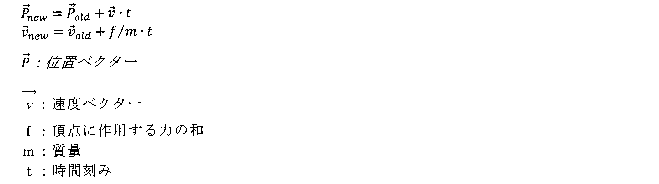
- the extension processing unit 102f updates the speed and the movement amount based on the calculated force acting between the three-dimensional vertices (step SG-3). More specifically, the extension processing unit 102f calculates a position vector and a movement vector from the force between the two vertices a and b based on the following formula.
- the extension processing unit 102f determines whether or not all vertex groups have reached the document table plane (predetermined depth) (step SG-4).
- the decompression processing unit 102f returns the process to step SG-2 and repeats the above-described process.
- the expansion processing unit 102f applies the current expanded length and the expansion to all mesh edges on the document table plane.
- the positions of the vertices are adjusted by comparing the previous original lengths (step SG-5). That is, the extension processing unit 102f compares the original length before extension shown in FIG. 18 with the length after extension shown in FIG. 19, and adjusts the vertex position of the mesh region.
- the decompression processing unit 102f determines whether or not a predetermined convergence condition is satisfied (step SG-6). If the predetermined convergence condition is not satisfied (step SG-6, No), the decompression processing unit 102f returns the process to step SG-5 and performs readjustment.
- step SG-6 When the predetermined convergence condition is satisfied (step SG-6, Yes), the extension processing unit 102f finishes the adjustment, acquires new coordinates of each vertex after extension as a new mesh set, and ends the process (step SG-7).
- FIG. 20 is a flowchart illustrating an example of mapping processing in the information processing apparatus 100.
- FIG. 21 is a diagram schematically illustrating a mapping process between a mesh set and an RGB image.
- the color mapping unit 102g acquires the original position (X, Y, Z) of the mesh square vertex before expansion by the expansion processing unit 102f stored in the three-dimensional file 106b (step SH- 1, FIG. 21 ⁇ MC-1>).
- the color mapping unit 102g acquires the color information (RGB image) stored in the image data temporary file 106a, and acquires the position (u, v) in the corresponding RGB image (step SH-2, FIG. 21 ⁇ MC-2>).
- the color mapping unit 102g acquires the position (X ′, Y ′, Z ′) of the new mesh square vertex that has been expanded by the expansion processing unit 102f (step SH-3, FIG. 21 ⁇ MC-3>). ).
- the color mapping unit 102g acquires the position (u ′, v ′) in the corresponding RGB image (step SH-4, FIG. 21 ⁇ MC-4>).
- the color mapping unit 102g obtains a perspective transformation matrix by using the four vertex RGB image positions (u, v) and (u ′, v ′) (step SH-5).
- the color mapping unit 102g obtains new RGB image coordinates of each pixel in the original square using the perspective transformation matrix and designates RGB information (step SH-6).
- the color mapping unit 102g acquires the two-dimensional RGB image subjected to distortion correction, and stores it in the processed image file 106c as processed image data.
- the above is an example of the color mapping process of the information processing apparatus 100 of the present embodiment.
- the information processing apparatus 100 acquires the three-dimensional information of the document, determines the document region based on the color and the depth in the three-dimensional information, and performs the crop processing on the document region. I do. As a result, even when the colors of the document table and the document are the same and it is difficult to extract the edge, the cropping can be accurately performed.
- the color edge is extracted from the color information and the depth edge is extracted from the depth information, and the document area is determined based on the color edge and the depth edge, so that the reliability of cropping can be further improved. Can do.
- the document area is determined by giving priority to the color edge out of the color edge and the depth edge, so that a beautiful document area can be acquired according to the apparent break.
- the document area is determined by giving priority to a point far from the center of the image, so that document missing can be prevented. it can.
- the original area is determined by giving priority to the depth edge obtained by scanning in the binding direction. Can be used to accurately determine the document area.
- the present invention may be implemented in various different embodiments other than the above-described embodiments within the scope of the technical idea described in the claims.
- the image reading unit 122 may detect light in a wavelength region other than the infrared region.
- processing is performed in response to a request from a client terminal in a separate casing from the information processing apparatus 100, and the processing result is You may make it return to a client terminal.
- all or a part of the processes described as being automatically performed can be manually performed, or all of the processes described as being manually performed can be performed. Alternatively, a part can be automatically performed by a known method.
- the processing procedures, control procedures, specific names, information including registration data for each processing, screen examples, and database configuration shown in the above documents and drawings may be arbitrarily changed unless otherwise specified. Can do.
- each illustrated component is functionally conceptual and does not necessarily need to be physically configured as illustrated.
- the processing functions provided in each device of the information processing apparatus 100 in particular, the processing functions performed by the control unit 102, all or any part thereof are interpreted and executed by a CPU (Central Processing Unit) and the CPU It may be realized by a program to be executed, or may be realized as hardware by wired logic.
- the program is recorded on a recording medium to be described later, and is mechanically read by the information processing apparatus 100 as necessary. That is, a computer program for performing various processes is recorded in the storage unit 106 such as a ROM or an HDD. This computer program is executed by being loaded into the RAM, and constitutes a control unit in cooperation with the CPU.
- the computer program may be stored in an application program server connected to the information processing apparatus 100 via an arbitrary network, and may be downloaded in whole or in part as necessary. is there.
- the program according to the present invention may be stored in a computer-readable recording medium, or may be configured as a program product.
- the “recording medium” includes a memory card, USB memory, SD card, flexible disk, magneto-optical disk, ROM, EPROM, EEPROM, CD-ROM, MO, DVD, and Blu-ray (registered trademark). It includes any “portable physical medium” such as Disc.
- the “program” is a data processing method described in an arbitrary language or description method, and may be in any format such as source code or binary code. Note that the “program” is not necessarily limited to a single configuration, but is distributed in the form of a plurality of modules and libraries, or in cooperation with a separate program typified by an OS (Operating System). Including those that achieve the function.
- OS Operating System
- a well-known structure and procedure can be used about the specific structure for reading a recording medium in each apparatus shown in embodiment, a reading procedure, or the installation procedure after reading.
- Various databases and the like (image data temporary file 106a, three-dimensional file 106b, and processed image file 106c) stored in the storage unit 106 are a memory device such as a RAM and a ROM, a fixed disk device such as a hard disk, a flexible disk, Storage means such as an optical disk, which stores various programs, tables, databases, and the like used for various processes.
- the information processing apparatus 100 may be configured as an information processing apparatus such as a known personal computer or workstation, or may be configured by connecting an arbitrary peripheral device to the information processing apparatus.
- the information processing apparatus 100 may be realized by installing software (including programs, data, and the like) that causes the information processing apparatus to implement the method of the present invention.
- the specific form of distribution / integration of the devices is not limited to that shown in the figure, and all or a part of them may be functional or physical in arbitrary units according to various additions or according to functional loads. Can be distributed and integrated. That is, the above-described embodiments may be arbitrarily combined and may be selectively implemented.
- the cropping apparatus, cropping method, and program according to the present invention can be implemented in many industrial fields, particularly in the image processing field that handles images read by a scanner, and are extremely useful.
Landscapes
- Engineering & Computer Science (AREA)
- Multimedia (AREA)
- Signal Processing (AREA)
- Physics & Mathematics (AREA)
- General Physics & Mathematics (AREA)
- Theoretical Computer Science (AREA)
- Editing Of Facsimile Originals (AREA)
- Character Input (AREA)
- Image Input (AREA)
- Image Processing (AREA)
Abstract
本実施形態によれば、原稿の3次元情報を取得し、3次元情報において、色および深度に基づいて原稿領域を判定してクロップ処理を行う。
Description
本発明は、クロッピング装置、クロッピング方法、および、プログラムに関する。
従来、オーバヘッドスキャナ等の画像読取装置において、本などの厚みのある綴じ媒体の画像を取得する場合に、原稿領域に応じてクロッピングする技術が開発されている。
例えば、直線成分、エッジ成分から輪郭を抽出して、抽出した輪郭に沿ってクロッピングを行う方法が開発されている(特許文献1を参照)。
また、カメラに関する位置およびカメラ較正パラメータのような既知のシステム配置情報を使用して、イメージから原稿範囲を直接決定する際に、何が文書に属していて何が属していないかを知るために、大きな曲率または奥行きの変化についての調査を用いてデータに適合される一般的な面を解析することによって原稿領域を判定する方法が開発されている(特許文献2を参照)。
しかしながら、従来のクロッピング方法では、原稿台と原稿の色が同等でエッジが抽出しにくいような場合など、正確にクロッピング対象の原稿領域を判定できず精度が低いという問題点を有していた。
本発明は、上記問題点に鑑みてなされたもので、原稿台と原稿の色が同等でエッジが抽出しにくいような場合であっても、精度よくクロッピングすることができる、クロッピング装置、クロッピング方法、および、プログラムを提供することを目的とする。
このような目的を達成するため、本発明に係るクロッピング装置は、原稿の3次元情報を取得する3次元情報取得手段と、3次元情報において、色および深度に基づいて原稿領域を判定して、当該原稿領域に対してクロップ処理を行うクロップ処理手段と、を備える。
また、本発明に係るクロッピング方法は、原稿の3次元情報を取得する3次元情報取得ステップと、3次元情報において、色および深度に基づいて上記原稿領域を判定してクロップ処理を行うクロップ処理ステップと、を含む。
また、本発明に係るプログラムは、原稿の3次元情報を取得する3次元情報取得ステップと、3次元情報において、色および深度に基づいて上記原稿領域を判定してクロップ処理を行うクロップ処理ステップと、をコンピュータに実行させる。
また、本発明に係るコンピュータ読み取り可能な記録媒体は、前記に記載の本発明に係るプログラムを記録する。
この発明によれば、原稿台と原稿の色が同等でエッジが抽出しにくいような場合であっても、精度よくクロッピングすることができる。
以下に、本発明に係るクロッピング装置、クロッピング方法、および、プログラムの実施形態を図面に基づいて詳細に説明する。なお、この実施形態により本発明が限定されるものではない。特に、本実施形態においては、読み取り対象を雑誌などの原稿として説明することがあるが、これに限られず、新聞紙や、ステープルで綴じられた媒体や、単票を重ねた束等を読み取り対象としてもよい。
[1.本実施形態の構成]
本実施形態に係る情報処理装置100の構成について図1を参照して説明する。図1は、情報処理装置100の一例を示すハードウェア構成図である。
本実施形態に係る情報処理装置100の構成について図1を参照して説明する。図1は、情報処理装置100の一例を示すハードウェア構成図である。
図1に示すように、本実施形態は、クロッピング方法を実行する情報処理装置100と、原稿画像を取得する画像読取装置12を備える。なお、情報処理装置100は、記憶部106および制御部102を備え、画像読取装置12は、パターン光源121および画像読取部122を備える。これら各部は任意の通信路を介して通信可能に接続されている。また、画像読取部122は、リニアセンサとエリアセンサのいずれであってもよく、あるいは2種類のセンサを備えてもよい。なお、本実施の形態において、パターン光源121を原稿に照射して3次元情報を取得する例について説明するが、これに限られず、パターン光源を用いずに、TOF(Time Of Flight)方式にて3次元情報を取得してもよい。
ここで、図2は、情報処理装置100の一例を示す機能ブロック図である。記憶部106は、各種のデータベースやテーブルやファイルなどを格納する。記憶部106は、ストレージ手段であり、例えばRAM・ROM等のメモリ装置や、ハードディスクのような固定ディスク装置、フレキシブルディスク、光ディスク等を用いることができる。記憶部106には、CPU(Central Processing Unit)に命令を与え各種処理を行うためのコンピュータプログラムが記録されている。ここで、図2は、情報処理装置100の記憶部106の一例を示すブロック図である。
図2に示すように、記憶部106は、図示の如く、画像データ一時ファイル106a、3次元ファイル106b、加工画像ファイル106cを備える。
このうち、画像データ一時ファイル106aは、読取制御部102aによりで読み取られた画像データを一時的に記憶する。
また、3次元ファイル106bは、画像データ一時ファイル106aに格納された画像データに基づいて生成された3次元情報を記憶する。
また、加工画像ファイル106cは、画像データ一時ファイル106aに格納された画像データ、および/または、3次元ファイル106bに格納された3次元情報から、加工または編集された加工画像データを記憶する。
入出力インターフェース部108は、入力部112および出力部114を、制御部102と接続する。入力部112としては、画像読取装置12等の画像読取手段のほか、マウスやキーボード等を用いることができ、出力部114としては、モニタやディスプレイ等の表示手段や、マイク等の音声出力手段を用いることができる。
制御部102は、情報処理装置100を統括的に制御するCPU等からなる。制御部102は、制御プログラムと各種の処理手順等を規定したプログラムと所要データとを格納するための内部メモリを有し、これらプログラムに基づいて種々の処理を実行するための情報処理を行う。
図2に示すように、制御部102は、図示の如く、大別して、読取制御部102aと、3次元情報取得部102bと、クロップ処理部102cと、メッシュ分割部102eと、伸張処理部102fと、色マッピング部102gとを備える。
読取制御部102aは、入力部112として画像読取装置12を制御して、原稿を含む画像を取得し、画像データ一時ファイル106aに格納する。例えば、読取制御部102aは、パターン光源121からパターン光が照射されるように制御して、画像読取部122を介して、パターン光が照射された原稿の画像を取得してもよい。より具体的には、読取制御部102aは、パターン光源121を制御して、対象物に対して位相パターンを照射し、パターン光源と同期するように、画像読取を実施する。この位相パターンを照射した複数枚の画像が取得されると、後述する、3次元情報取得部102bが3次元形状を復元する。このほか、読取制御部102aは、パターン光を照射することなく、原稿の色情報(RGB情報等)を取得してもよい。すなわち、前者によって、深度情報が取得され、後者によって、色情報が取得されることとなる。
3次元情報取得部102bは、画像データ一時ファイル106aに格納された、パターン光が照射された原稿を含む画像データに基づいて、深度情報を含む3次元情報を取得し、3次元ファイル106bに格納する。例えば、3次元情報取得部102bは、公知のパターン光投影法に基づいて、3次元情報を取得してもよい。なお、3次元情報取得部102bは、公知のTOF方式に基づいて、3次元情報を取得してもよい。
クロップ処理部102cは、3次元情報において原稿領域をクロップ処理する。例えば、クロップ処理部102cは、3次元ファイル106bに格納された3次元情報において、色および深度に基づいて原稿領域を判定し、当該原稿領域に対してクロップ処理を行ってもよい。なお、クロップ処理部102cは、判定した原稿領域の外側の背景領域の深度情報を、伸張処理部102f等による後処理のために取得してもよい。なお、クロップ処理部102cは、クロップ処理した原稿領域の3次元情報を、3次元ファイル106bに格納する。
ここで、図2に示すように、本実施形態において、クロップ処理部102cは、画像データ一時ファイル106aに格納された色情報から色エッジ、および、3次元ファイル106bに格納された深度情報から深度エッジを抽出するエッジ抽出部102dを備える。そして、クロップ処理部102cは、エッジ抽出部102dにより抽出された色エッジおよび深度エッジに基づいて原稿領域を判定してもよい。ここで、クロップ処理部102cは、色エッジおよび深度エッジのうち、色エッジを優先して原稿領域を判定してもよい。より具体的には、色エッジおよび深度エッジの対応点間の距離が近い場合、深度よりも見た目の切れ目でクロップを行うため、クロップ処理部102cは、色エッジを優先して原稿領域を判定してもよい。
ここで、エッジ抽出部102dにより抽出された色エッジと深度エッジの対応点間の距離が閾値を超える場合、クロップ処理部102cは、画像中心から遠い点を優先して原稿領域を判定してもよい。換言すれば、色エッジと深度エッジの対応点間の距離が閾値を超える場合、原稿よりも外側で誤検出が起こることはないと考え、原稿欠けを防止してクロッピングの信頼性を上げるために、クロップ処理部102cは、色エッジおよび深度エッジのうち、画像中心から遠い点を優先して原稿領域を判定する。
クロップ処理部102cは、原稿が綴じられた媒体であるときは、綴じ方向の走査により得られた深度エッジを優先して原稿領域を判定してもよい。すなわち、厚みのある綴じ媒体である場合、自然な紙の浮き上がりなどで立体的な形状の変化が起こるので、綴じ方向に深度エッジが現れやすい。そのため、クロップ処理部102cは、綴じ方向の走査により得られた深度エッジを色エッジよりも優先して原稿領域を判定する。反対に、クロップ処理部102cは、綴じ方向とは垂直方向の走査により得られた色エッジを深度エッジよりも優先して原稿領域を判定してもよい。
メッシュ分割部102eは、3次元情報を矩形メッシュに分割する。本実施形態において、メッシュ分割部102eは、3次元情報を矩形メッシュに分割する場合において、深度に応じて適応的に細かくメッシュ分割する。より具体的には、メッシュ分割部102eは、3次元情報に対して、メッシュ分割した近似平面の誤差が閾値以上ある場合に、当該矩形メッシュを更に複数の矩形にメッシュ分割する処理を繰り返す。これにより、紙の浮きや折り目などに応じて細かくメッシュを設定することができ、特にメッシュ間に折り目などの顕著な変化点が存在する場合は、更に細かくメッシュを設定することができるので、歪み補正の精度が向上する。
ここで、メッシュ分割部102eは、3次元情報取得部102bにより取得された原稿領域と背景領域を含む3次元情報を矩形メッシュに分割することに限られず、クロップ処理部102cによりクロップ処理された原稿領域の3次元情報を矩形メッシュに分割してもよい。これにより、原稿領域のみの3次元情報を扱うことができ、演算負荷の軽減や、後述するばねモデルを用いることによる背景領域から悪影響を除去することができる。なお、本実施形態においては、原稿領域のクロップ処理によって、背景領域の3次元情報を除去する例について説明するが、これに限られず、読取制御部102aによる読取を行う際に、透明な原稿台に原稿を載置することによっても原稿領域のみの3次元情報を取得することができる。
伸張処理部102fは、メッシュ分割部102eにより分割した3次元情報を平面に伸張させる。より具体的には、伸張処理部102fは、メッシュ分割した各領域の3次元頂点間に、ばねモデルを適用した上で、3次元頂点を基準平面に伸張させる。ここで、伸張処理部102fは、3次元情報取得部102bにより取得された3次元情報において、クロップ処理部102cにより原稿領域と判定された領域の外側の背景領域の深度を、基準面の深度として平面に伸張させてもよい。なお、画像読取装置12と原稿台の位置関係が予め固定である場合等においては、伸張処理部102fは、予め設定された所定の深度平面に対して伸張させてもよい。
色マッピング部102gは、伸張処理部102fにより伸張された平面データ上に、画像データ一時ファイル106aに記憶された色情報をマッピングする。より具体的には、色マッピング部102gは、画像データ一時ファイル106aに記憶された色情報(RGB情報等)について、伸張前の矩形メッシュ形状から伸張後の矩形メッシュ形状への変形が反映されるように、平面データ上にマッピングする。
[2.本実施形態の処理]
上述した構成の情報処理装置100で実行される処理例について、図3~図21を参照して説明する。なお、以下の実施形態の処理では、クロッピング方法のみならず、原稿歪み補正方法をも実施する例について説明するが、本願発明は、この処理例に限定されるものではなく、クロッピング方法など説明中の一部処理のみを本願発明の対象としてもよいものである。
上述した構成の情報処理装置100で実行される処理例について、図3~図21を参照して説明する。なお、以下の実施形態の処理では、クロッピング方法のみならず、原稿歪み補正方法をも実施する例について説明するが、本願発明は、この処理例に限定されるものではなく、クロッピング方法など説明中の一部処理のみを本願発明の対象としてもよいものである。
[2-1.全体処理(その1)]
本実施形態の情報処理装置100における全体処理の一例について図3を参照して説明する。図3は、画像読取装置12から原稿台までの位置関係が固定である場合の情報処理装置100における全体処理の一例を示すフローチャートである。
本実施形態の情報処理装置100における全体処理の一例について図3を参照して説明する。図3は、画像読取装置12から原稿台までの位置関係が固定である場合の情報処理装置100における全体処理の一例を示すフローチャートである。
図3に示すように、まず、3次元情報取得部102bは、読取制御部102aの処理により、画像読取装置12を制御して、原稿が載置されていない原稿台の画像を取得することにより、原稿台の深度情報を取得する(ステップSA-1)。なお、この処理は、初回だけ行われる処理であり、画像読取装置12から原稿台までの位置関係が固定であるため、2回目以降は、同じ原稿台の深度を利用する。
つづいて、3次元情報取得部102bは、読取制御部102aの処理により、画像読取装置12を制御して、原稿が載置された原稿台の画像を取得することにより、原稿の色情報と3次元情報(深度情報等)を取得する(ステップSA-2)。なお、この3次元情報には、原稿領域と背景領域の3次元情報が含まれている。
そして、クロップ処理部102cは、3次元情報において、色および深度に基づいて原稿領域を判定し、当該原稿領域に対してクロップ処理を行う(ステップSA-3)。これにより、原稿領域のみの3次元情報が得られる。
そして、メッシュ分割部102eは、深度に応じて適応的に細かくメッシュ分割することにより、3次元情報を矩形メッシュに分割する(ステップSA-4)。より具体的には、メッシュ分割部102eは、3次元情報に対して、メッシュ分割した近似平面の誤差が閾値以上ある場合に、当該矩形メッシュを更に複数の矩形にメッシュ分割する処理を繰り返すことで、歪みに応じて適応的に細かくメッシュ分割を行う。
そして、伸張処理部102fは、メッシュ分割部102eにより分割した3次元情報を、ステップSA-1で得られた固定の深度の平面に伸張させる(ステップSA-5)。より具体的には、伸張処理部102fは、メッシュ分割した各領域の3次元頂点間に、ばねモデルを適用した上で、3次元頂点を、深度固定の基準平面に伸張させる。
そして、色マッピング部102gは、伸張処理部102fにより伸張された平面データ上に、画像データ一時ファイル106aに記憶された色情報をマッピングする(ステップSA-6)。より具体的には、色マッピング部102gは、画像データ一時ファイル106aに記憶された色情報(RGB情報等)について、伸張前の矩形メッシュ形状から伸張後の矩形メッシュ形状への変形が反映されるように、平面データ上にマッピングする。
以上が、本実施形態の情報処理装置100における全体処理の一例である。
[2-2.全体処理(その2)]
ここで、上述した全体処理の他の例について図4を参照して説明する。図4は、画像読取装置12から原稿台までの位置関係が可変である場合の情報処理装置100における全体処理の一例を示すフローチャートである。
ここで、上述した全体処理の他の例について図4を参照して説明する。図4は、画像読取装置12から原稿台までの位置関係が可変である場合の情報処理装置100における全体処理の一例を示すフローチャートである。
図4に示すように、まず、3次元情報取得部102bは、読取制御部102aの処理により、画像読取装置12を制御して、原稿が載置された原稿台の画像を取得することにより、原稿の色情報と3次元情報(深度情報等)を取得する(ステップSB-1)。なお、この3次元情報には、原稿領域と背景領域の3次元情報が含まれている。
そして、クロップ処理部102cは、3次元情報において、色および深度に基づいて原稿領域を判定し、当該原稿領域に対してクロップ処理を行う(ステップSB-2)。これにより、原稿領域のみの3次元情報が得られる。
そして、クロップ処理部102cは、原稿領域と判定した外側の領域である背景領域の深度情報を、原稿台の平面の深度情報と推定して取得する(ステップSB-3)。ここで、図5は、原稿と原稿が載置された原稿台の関係を模式的に示した図である。図5に示すように、原稿領域の外側の背景領域は、原稿台の深度を表すことになるので、背景領域の深度情報を、原稿台の深度と推定することができる。
そして、メッシュ分割部102eは、深度に応じて適応的に細かくメッシュ分割することにより、3次元情報を矩形メッシュに分割する(ステップSB-4)。より具体的には、メッシュ分割部102eは、3次元情報に対して、メッシュ分割した近似平面の誤差が閾値以上ある場合に、当該矩形メッシュを更に複数の矩形にメッシュ分割する処理を繰り返すことで、歪みに応じて適応的に細かくメッシュ分割を行う。
そして、伸張処理部102fは、メッシュ分割部102eにより分割した3次元情報を、ステップSB-3で推定された原稿台の深度の平面に伸張させる(ステップSB-5)。より具体的には、伸張処理部102fは、メッシュ分割した各領域の3次元頂点間に、ばねモデルを適用した上で、3次元頂点を、推定された原稿台深度の基準平面に伸張させる。
そして、色マッピング部102gは、伸張処理部102fにより伸張された平面データ上に、画像データ一時ファイル106aに記憶された色情報をマッピングする(ステップSB-6)。より具体的には、色マッピング部102gは、画像データ一時ファイル106aに記憶された色情報(RGB情報等)について、伸張前の矩形メッシュ形状から伸張後の矩形メッシュ形状への変形が反映されるように、平面データ上にマッピングする。
以上が、本実施形態の情報処理装置100における全体処理の一例である。
[2-3.クロッピング処理(その1)]
ここで、上述した全体処理における、より具体的なクロッピング処理の例について図6および図7を参照して説明する。図6は、本実施形態の情報処理装置100におけるクロッピング処理の一例を示すフローチャートである。また、図7は、図6におけるクロッピング処理の出力概念図である。
ここで、上述した全体処理における、より具体的なクロッピング処理の例について図6および図7を参照して説明する。図6は、本実施形態の情報処理装置100におけるクロッピング処理の一例を示すフローチャートである。また、図7は、図6におけるクロッピング処理の出力概念図である。
図6に示すように、まず、クロップ処理部102cは、エッジ抽出部102dの処理により、画像データ一時ファイル106aに格納された色情報、および、3次元ファイル106bに格納された深度情報から、それぞれ色エッジと深度エッジを抽出する(ステップSC-1)。ここで、図7のMA-1は、抽出前の原稿綴じ媒体を示した図であり、MA-2は、色エッジの抽出例、MA-3は、深度エッジの抽出例を示している。なお、破線は、何らかの原因でエッジが抽出できなかった箇所を表している。また、白抜き線は、色エッジを表しており、一点鎖線は、深度エッジを表している。
再び図6に戻り、クロップ処理部102cは、抽出した色エッジと深度エッジの各エッジについて輪郭を検出する(ステップSC-2)。ここで、クロップ処理部102cは、色と深度を用いて、以下のようにクロッピングの信頼性を向上させる。
すなわち、画像全体に対して、以下のSC-3~SC-8の処理を繰り返し実行する。
繰り返し処理において、クロップ処理部102cは、色と深度の最外の輪郭について対応点を検出する(ステップSC-4)。
そして、クロップ処理部102cは、色と深度の対応点間の距離が閾値以下であるか否かを判定する(ステップSC-5)。
色と深度の対応点間の距離が閾値以下である場合(ステップSC-5,Yes)、クロップ処理部102cは、色エッジの点をクロッピング対象点として、クロッピング対象の原稿領域を判定する(ステップSC-6)。ここで、図7のMA-4は、色エッジと深度エッジを重ね合わせた図である。図7に示すように、水平方向では、色エッジと深度エッジの両方が検出されており、この例では両者間は閾値以下であるので、色エッジがクロッピング対象点として選ばれる。これにより、深度よりも見た目の切れ目でクロップを行うことができる。
一方、色と深度の対応点間の距離が閾値を超える場合(ステップSC-5,No)、クロップ処理部102cは、画像中心から遠い点をクロッピング対象点として、クロッピング対象の原稿領域を判定する(ステップSC-7)。原稿よりも外側で誤検出が起こることはないと考えられるので、これにより、原稿欠けを防止してクロッピングの信頼性を向上させることができる。
以上の繰り返し処理(ステップSC-3~SC-8)が画像全体について実行されると、クロップ処理部102cは、判定したクロッピング対象点群を結んだものを、クロッピング対象の原稿領域と判定する(ステップSC-9)。
以上が、本実施形態の情報処理装置100におけるクロッピング処理の一例である。
[2-4.クロッピング処理(その2)]
ここで、上述した全体処理におけるクロッピング処理の他の例について図8および図9を参照して説明する。図8は、本実施形態の情報処理装置100におけるクロッピング処理の他の例を示すフローチャートである。また、図9は、図8におけるクロッピング処理の出力概念図である。
ここで、上述した全体処理におけるクロッピング処理の他の例について図8および図9を参照して説明する。図8は、本実施形態の情報処理装置100におけるクロッピング処理の他の例を示すフローチャートである。また、図9は、図8におけるクロッピング処理の出力概念図である。
図8に示すように、まず、クロップ処理部102cは、エッジ抽出部102dの処理により、画像データ一時ファイル106aに格納された色情報から水平方向の色エッジを抽出し、3次元ファイル106bに格納された深度情報から垂直方向の深度エッジを抽出する(ステップSD-1)。ここで、図9のMB-1は、エッジ抽出前の原稿綴じ媒体を示した図であり、MB-2は、水平方向の色エッジの抽出例、MB-3は、垂直方向の深度エッジの抽出例を示している。なお、破線は、何らかの原因でエッジが抽出できなかった箇所を表している。
図9において、白抜き線は、水平方向の色エッジを表しており、一点鎖線は、垂直方向の深度エッジを表している。本実施形態のクロッピング処理(その2)では、綴じ媒体が原稿である場合に、その綴じ方向で深度エッジが現れやすいため、垂直方向の深度エッジを検出する。一方、綴じ方向とは垂直な水平方向では、深度エッジが検出しにくいので、色エッジを優先する。
すなわち、図8および図9<MB-3>に示すように、クロップ処理部102cは、抽出した垂直方向の深度エッジから、画像中の最上および最下の連続したエッジT(Top),B(Bottom)を検出する(SD-2)。
そして、図8および図9<MB-2>に示すように、クロップ処理部102cは、抽出した水平方向の色エッジから、画像中の最左および最右の連続したエッジL(Left),R(Right)を検出する(SD-3)。
そして、クロップ処理部102cは、エッジT,Bの各々の端点と、エッジL,Rとの最短距離が閾値以下であるか否かを判定する(ステップSD-4)。
最短距離が閾値以下である場合(ステップSD-4,Yes)、クロップ処理部102cは、図9<MB-4>に示すように、エッジT,BとエッジL,Rを統合して、クロップ対象の原稿領域を判定する(ステップSD-5)。これにより、深度エッジが現れにくい水平方向では、見た目の切れ目でクロップを行うことができる。
一方、最短距離が閾値を超える場合(ステップSD-4,No)、クロップ処理部102cは、図9<MB-5>に示すように、エッジL,Rを使用せずに、深度エッジT,Bの両端点を結んで、クロップ対象の原稿領域を判定する(ステップSD-6)。これにより、深度よりも見た目の切れ目でクロップを行うことができる。これにより、原稿欠けを防止して、信頼性の高いクロップを行うことができる。
以上が、本実施形態の情報処理装置100におけるクロッピング処理の他の例である。
[2-5.原稿台深度推定処理]
本実施形態の情報処理装置100における原稿台深度推定処理の一例について図10および図11を参照して説明する。図10は、画像読取装置12から原稿台までの位置関係が未知である場合の情報処理装置100における原稿台深度推定処理の一例を示すフローチャートである。また、図11は、原稿台に載置された原稿を模式的に示した図である。
本実施形態の情報処理装置100における原稿台深度推定処理の一例について図10および図11を参照して説明する。図10は、画像読取装置12から原稿台までの位置関係が未知である場合の情報処理装置100における原稿台深度推定処理の一例を示すフローチャートである。また、図11は、原稿台に載置された原稿を模式的に示した図である。
図10に示すように、まず、3次元情報取得部102bは、3次元ファイル106bを参照して、予め原稿台の平面情報が取得されているか否かを判定する(ステップSE-1)。
予め原稿台の平面情報が取得されている場合(ステップSE-1,Yes)、原稿台深度推定処理を終え、一方、原稿台の平面情報が未だ取得されていない場合(ステップSE-1,No)、3次元情報取得部102bは、原稿領域の外側の背景領域に基づいて、原稿台の平面情報を取得する(ステップSE-2)。より具体的には、図11に示すように、3次元情報取得部102bは、クロップ処理部102cにより判定された原稿領域の外側の背景領域の3次元情報から平面ax+by+cz+d=0を求めることにより、原稿台の領域である背景領域の3次元情報から平面近似を行い原稿台の平面情報を取得する。
以上が、本実施形態の情報処理装置100における原稿台深度推定処理の例である。
[2-6.メッシュ分割処理]
本実施形態の情報処理装置100におけるメッシュ分割処理の一例について図12~図15を参照して説明する。図12は、情報処理装置100におけるメッシュ分割処理の一例を示すフローチャートである。また、図13および図14は、原稿領域がメッシュ分割される様子を模式的に示した図である。また、図15は、最終的にメッシュ分割された結果を模式的に示す図である。
本実施形態の情報処理装置100におけるメッシュ分割処理の一例について図12~図15を参照して説明する。図12は、情報処理装置100におけるメッシュ分割処理の一例を示すフローチャートである。また、図13および図14は、原稿領域がメッシュ分割される様子を模式的に示した図である。また、図15は、最終的にメッシュ分割された結果を模式的に示す図である。
図12に示すように、まず、メッシュ分割部102eは、クロップ処理部102cによりクロップ処理された原稿領域の3次元情報に基づく媒体曲面に対して、原稿台平面と垂直する平面で荒く矩形メッシュに分割する(ステップSF-1)。すなわち、図13に示すように、メッシュ分割部102eは、原稿領域の3次元情報を、所定の大きさのメッシュに均等分割してもよい。
そして、メッシュ分割部102eは、メッシュ分割した各領域内の3次元ポイント群を平面に近似する(ステップSF-2)。
そして、メッシュ分割部102eは、メッシュ分割した各領域内の3次元ポイントと近似平面との距離(誤差)を計算する(ステップSF-3)。
近似平面との距離が閾値以上である場合(ステップSF-4,Yes)、メッシュ分割部102eは、メッシュ分割した領域中で距離が一番大きなポイントを検出して、このポイントを通る垂直平面で更に細かい矩形メッシュに分割して、新たな領域を追加する(ステップSF-5)。図14に示すように、最初の6分割メッシュにおいて、上段中央のメッシュの歪み量が大きく平面に近似しようとすると誤差が閾値以上となる場合、メッシュ分割部102eは、1つの矩形メッシュを4つの矩形メッシュに分割する。
一方、近似平面との距離が閾値未満である場合(ステップSF-4,No)、当該処理は行わず、次のステップに進む。
そして、メッシュ分割部102eは、分割された全てのメッシュ領域についてチェックが終了したか否かを判定する(ステップSF-6)。まだ、判定を行っていないメッシュ領域がある場合は(ステップSF-6,No)、次の領域についてステップSF-2に戻り上述した処理を繰り返す。換言すると、近似平面と実際の3次元情報との距離に差がある場合は、メッシュ領域面積を小さくし、同様の処理を繰り返す。すなわち、深度が急峻に変化する領域は細かくメッシュ化され、ゆるやかな部分は広い範囲でメッシュ化される。
一方、全てのメッシュ領域についてチェックが終了すると(ステップSF-6,Yes)、分割したメッシュ集合を記録して処理を終える(ステップSF-7)。図15に示すように、最終的に分割されたメッシュ領域は、原稿の歪み量に応じて適応的に細かくメッシュ分割が行われる。これにより、紙の浮きや折り目などに応じて細かくメッシュを設定することができ、特にメッシュ間に折り目などの顕著な変化点が存在する場合は、更に細かくメッシュを設定することができるので、歪み補正の精度が向上する。
以上が、本実施形態の情報処理装置100におけるメッシュ分割処理の例である。
[2-7.伸張処理]
本実施形態の情報処理装置100における伸張処理の一例について図16~図19を参照して説明する。図16は、本実施形態において適用するばねモデルを模式的に示した図である。図17は、情報処理装置100における伸張処理の一例を示すフローチャートである。また、図18は、伸張前の旧メッシュ集合を示した図であり、図19は、伸張後の新メッシュ集合を示した図である。
本実施形態の情報処理装置100における伸張処理の一例について図16~図19を参照して説明する。図16は、本実施形態において適用するばねモデルを模式的に示した図である。図17は、情報処理装置100における伸張処理の一例を示すフローチャートである。また、図18は、伸張前の旧メッシュ集合を示した図であり、図19は、伸張後の新メッシュ集合を示した図である。
伸張処理を行うにあたって、本実施形態では、ばねモデルを適用する。図16に示すように、3次元頂点をV(X,Y,Z)とおくと、2つの3次元頂点a,b間には、ばね係数K_dのばねがあるかのように収縮・伸張させる(M.S. Brown著” Document restoration using 3D shape: a general deskewing algorithm for arbitrarily warped documents, Computer Vision, 2001”参照)。
具体的な伸張処理として、図17に示すように、まず、伸張処理部102fは、メッシュ分割部102eにより分割した3次元情報をデモデリングして、3次元頂点を抽出する(ステップSG-1)。
そして、伸張処理部102fは、3次元頂点群の各頂点に作用する力を計算する(ステップSG-2)。より具体的には、伸張処理部102fは、下記の式に基づいて、2つの頂点a,b間の力を計算する。

そして、伸張処理部102fは、計算した3次元頂点間にはたらく力に基づいて、スピードと移動量を更新する(ステップSG-3)。より具体的には、伸張処理部102fは、下記の式に基づいて、2つの頂点a,b間の力から位置ベクトルと移動ベクトルを計算する。
そして、伸張処理部102fは、全ての頂点群が、原稿台平面(所定の深度)に到達したか否かを判定する(ステップSG-4)。
全ての頂点群が原稿台平面に到達していない場合(SG-4,No)、伸張処理部102fは、ステップSG-2に処理を戻し、上述した処理を繰り返す。
一方、全ての頂点群が原稿台平面に到達した場合(SG-4,Yes)、伸張処理部102fは、原稿台平面上ですべてのメッシュエッジに対して、現在の伸張後の長さと、伸張前の原長を比較して、頂点の位置を調整する(ステップSG-5)。すなわち、伸張処理部102fは、図18に示す伸張前の原長と、図19に示す伸張後の長さとを比較して、メッシュ領域の頂点位置を調整する。
そして、伸張処理部102fは、所定の収束条件を満たしたか否かを判定する(ステップSG-6)。所定の収束条件を満たしていない場合は(ステップSG-6,No)、伸張処理部102fは、ステップSG-5に処理を戻し、再調整を行う。
所定の収束条件を満たした場合(ステップSG-6,Yes)、伸張処理部102fは、調整を終了して、伸張後の各頂点の新しい座標を新メッシュ集合として取得して処理を終える(ステップSG-7)。
以上が、本実施形態の情報処理装置100における伸張処理の例である。
[2-8.マッピング処理]
本実施形態の情報処理装置100におけるマッピング処理の一例について図20および図21を参照して説明する。図20は、情報処理装置100におけるマッピング処理の一例を示すフローチャートである。また、図21は、メッシュ集合とRGB画像とのマッピング処理を模式的に示した図である。
本実施形態の情報処理装置100におけるマッピング処理の一例について図20および図21を参照して説明する。図20は、情報処理装置100におけるマッピング処理の一例を示すフローチャートである。また、図21は、メッシュ集合とRGB画像とのマッピング処理を模式的に示した図である。
図20に示すように、色マッピング部102gは、3次元ファイル106bに記憶された、伸張処理部102fによる伸張前のメッシュ四角頂点の元位置(X,Y,Z)を取得する(ステップSH-1,図21<MC-1>)。
そして、色マッピング部102gは、画像データ一時ファイル106aに記憶された色情報(RGB画像)を取得して、対応するRGB画像中の位置(u,v)を取得する(ステップSH-2,図21<MC-2>)。
そして、色マッピング部102gは、伸張処理部102fにより伸張された後の新メッシュ四角頂点の位置(X´,Y´,Z´)を取得する(ステップSH-3,図21<MC-3>)。
そして、色マッピング部102gは、対応するRGB画像中の位置(u´,v´)を取得する(ステップSH-4,図21<MC-4>)。
そして、色マッピング部102gは、4つの頂点RGB画像位置(u,v)と(u´,v´)を用いて、透視変換マトリクスを求める(ステップSH-5)。
そして、色マッピング部102gは、透視変換マトリクスを用いて、元四角中の各ピクセルの新しいRGB画像座標を求めてRGB情報を指定する(ステップSH-6)。
以上の処理により、色マッピング部102gは、歪み補正が行われた2次元RGB画像を取得し、加工画像データとして加工画像ファイル106cに格納する。
以上が、本実施形態の情報処理装置100の色マッピング処理の例である。
[3.本実施形態のまとめ、及び他の実施形態]
以上、本実施形態によれば、情報処理装置100は、原稿の3次元情報を取得し、3次元情報において、色および深度に基づいて原稿領域を判定して、当該原稿領域に対してクロップ処理を行う。これにより、原稿台と原稿の色が同等でエッジが抽出しにくいような場合であっても、精度よくクロッピングすることができる。
以上、本実施形態によれば、情報処理装置100は、原稿の3次元情報を取得し、3次元情報において、色および深度に基づいて原稿領域を判定して、当該原稿領域に対してクロップ処理を行う。これにより、原稿台と原稿の色が同等でエッジが抽出しにくいような場合であっても、精度よくクロッピングすることができる。
また、本実施形態によれば、色情報から色エッジ、および、深度情報から深度エッジを抽出し、色エッジおよび深度エッジに基づいて原稿領域を判定するので、クロッピングの信頼性を一層向上させることができる。
また、本実施形態によれば、色エッジおよび深度エッジのうち、色エッジを優先して原稿領域を判定するので、見た目上の切れ目に応じて綺麗な原稿領域を取得することができる。
また、本実施形態によれば、色エッジと深度エッジの対応点間の距離が閾値を超える場合は、画像中心から遠い点を優先して原稿領域を判定するので、原稿欠けを防止することができる。
また、本実施形態によれば、原稿が綴じられた媒体であるときは、綴じ方向の走査により得られた深度エッジを優先して上記原稿領域を判定するので、深度エッジが現れやすい方向のエッジを利用して、正確に原稿領域を判定することができる。
さらに、本発明は、上述した実施形態以外にも、特許請求の範囲に記載した技術的思想の範囲内において種々の異なる実施形態にて実施されてよいものである。例えば、画像読取部122は、赤外領域以外の波長領域の光を検出してもよい。また、情報処理装置100がスタンドアローンの形態で処理を行う場合を一例に説明したが、情報処理装置100とは別筐体のクライアント端末からの要求に応じて処理を行い、その処理結果を当該クライアント端末に返却するようにしてもよい。また、実施形態において説明した各処理のうち、自動的に行われるものとして説明した処理の全部または一部を手動的に行うこともでき、あるいは、手動的に行われるものとして説明した処理の全部または一部を公知の方法で自動的に行うこともできる。このほか、上記文献中や図面中で示した処理手順、制御手順、具体的名称、各処理の登録データを含む情報、画面例、データベース構成については、特記する場合を除いて任意に変更することができる。
また、情報処理装置100に関して、図示の各構成要素は機能概念的なものであり、必ずしも物理的に図示の如く構成されていることを要しない。例えば、情報処理装置100の各装置が備える処理機能、特に制御部102にて行われる各処理機能については、その全部または任意の一部を、CPU(Central Processing Unit)および当該CPUにて解釈実行されるプログラムにて実現してもよく、また、ワイヤードロジックによるハードウェアとして実現してもよい。尚、プログラムは、後述する記録媒体に記録されており、必要に応じて情報処理装置100に機械的に読み取られる。すなわち、ROMまたはHDDなどの記憶部106などには、各種処理を行うためのコンピュータプログラムが記録されている。このコンピュータプログラムは、RAMにロードされることによって実行され、CPUと協働して制御部を構成する。また、このコンピュータプログラムは、情報処理装置100に対して任意のネットワークを介して接続されたアプリケーションプログラムサーバに記憶されていてもよく、必要に応じてその全部または一部をダウンロードすることも可能である。
また、本発明に係るプログラムを、コンピュータ読み取り可能な記録媒体に格納してもよく、また、プログラム製品として構成することもできる。ここで、この「記録媒体」とは、メモリーカード、USBメモリ、SDカード、フレキシブルディスク、光磁気ディスク、ROM、EPROM、EEPROM、CD-ROM、MO、DVD、および、Blu-ray(登録商標) Disc等の任意の「可搬用の物理媒体」を含むものとする。また、「プログラム」とは、任意の言語や記述方法にて記述されたデータ処理方法であり、ソースコードやバイナリコード等の形式を問わない。なお、「プログラム」は必ずしも単一的に構成されるものに限られず、複数のモジュールやライブラリとして分散構成されるものや、OS(Operating System)に代表される別個のプログラムと協働してその機能を達成するものをも含む。なお、実施形態に示した各装置において記録媒体を読み取るための具体的な構成、読み取り手順、あるいは、読み取り後のインストール手順等については、周知の構成や手順を用いることができる。
記憶部106に格納される各種のデータベース等(画像データ一時ファイル106a、3次元ファイル106b、加工画像ファイル106c)は、RAM、ROM等のメモリ装置、ハードディスク等の固定ディスク装置、フレキシブルディスク、および、光ディスク等のストレージ手段であり、各種処理に用いる各種のプログラム、テーブル、および、データベース等を格納する。
また、情報処理装置100は、既知のパーソナルコンピュータ、ワークステーション等の情報処理装置として構成してもよく、また、該情報処理装置に任意の周辺装置を接続して構成してもよい。また、情報処理装置100は、該情報処理装置に本発明の方法を実現させるソフトウェア(プログラム、データ等を含む)を実装することにより実現してもよい。更に、装置の分散・統合の具体的形態は図示するものに限られず、その全部または一部を、各種の付加等に応じて、または、機能負荷に応じて、任意の単位で機能的または物理的に分散・統合して構成することができる。すなわち、上述した実施形態を任意に組み合わせて実施してもよく、実施形態を選択的に実施してもよい。
以上のように、本発明に係るクロッピング装置、クロッピング方法、および、プログラムは、産業上の多くの分野、特にスキャナで読み取った画像を扱う画像処理分野で実施することができ、極めて有用である。
12 画像読取装置
121 パターン光源
122 画像読取部
100 情報処理装置
102 制御部
102a 読取制御部
102b 3次元情報取得部
102c クロップ処理部
102d エッジ抽出部
102e メッシュ分割部
102f 伸張処理部
102g 色マッピング部
106 記憶部
106a 画像データ一時ファイル
106b 3次元ファイル
106c 加工画像ファイル
108 入出力インターフェース部
112 入力部
114 出力部
121 パターン光源
122 画像読取部
100 情報処理装置
102 制御部
102a 読取制御部
102b 3次元情報取得部
102c クロップ処理部
102d エッジ抽出部
102e メッシュ分割部
102f 伸張処理部
102g 色マッピング部
106 記憶部
106a 画像データ一時ファイル
106b 3次元ファイル
106c 加工画像ファイル
108 入出力インターフェース部
112 入力部
114 出力部
Claims (7)
- 原稿の3次元情報を取得する3次元情報取得手段と、
3次元情報において、色および深度に基づいて原稿領域を判定して、当該原稿領域に対してクロップ処理を行うクロップ処理手段と、
を備えることを特徴とするクロッピング装置。 - 請求項1に記載のクロッピング装置において、
上記クロップ処理手段は、
色情報から色エッジ、および、深度情報から深度エッジを抽出するエッジ抽出手段、
を更に備え、
上記色エッジおよび上記深度エッジに基づいて上記原稿領域を判定することを特徴とするクロッピング装置。 - 請求項2に記載のクロッピング装置において、
上記クロップ処理手段は、
上記色エッジおよび上記深度エッジのうち、上記色エッジを優先して上記原稿領域を判定することを特徴とするクロッピング装置。 - 請求項3に記載のクロッピング装置において、
上記クロップ処理手段は、
上記色エッジと上記深度エッジの対応点間の距離が閾値を超える場合は、画像中心から遠い点を優先して上記原稿領域を判定することを特徴とするクロッピング装置。 - 請求項1乃至4のいずれか一つに記載のクロッピング装置において、
上記クロップ処理手段は、
原稿が綴じられた媒体であるときは、綴じ方向の走査により得られた深度エッジを優先して上記原稿領域を判定することを特徴とするクロッピング装置。 - 原稿の3次元情報を取得する3次元情報取得ステップと、
3次元情報において、色および深度に基づいて上記原稿領域を判定してクロップ処理を行うクロップ処理ステップと、
を含むことを特徴とするクロッピング方法。 - 原稿の3次元情報を取得する3次元情報取得ステップと、
3次元情報において、色および深度に基づいて上記原稿領域を判定してクロップ処理を行うクロップ処理ステップと、
をコンピュータに実行させるためのプログラム。
Priority Applications (2)
| Application Number | Priority Date | Filing Date | Title |
|---|---|---|---|
| PCT/JP2014/057914 WO2015141011A1 (ja) | 2014-03-20 | 2014-03-20 | クロッピング装置、クロッピング方法、および、プログラム |
| JP2016508436A JP6194408B2 (ja) | 2014-03-20 | 2014-03-20 | クロッピング装置、クロッピング方法、および、プログラム |
Applications Claiming Priority (1)
| Application Number | Priority Date | Filing Date | Title |
|---|---|---|---|
| PCT/JP2014/057914 WO2015141011A1 (ja) | 2014-03-20 | 2014-03-20 | クロッピング装置、クロッピング方法、および、プログラム |
Publications (1)
| Publication Number | Publication Date |
|---|---|
| WO2015141011A1 true WO2015141011A1 (ja) | 2015-09-24 |
Family
ID=54144011
Family Applications (1)
| Application Number | Title | Priority Date | Filing Date |
|---|---|---|---|
| PCT/JP2014/057914 Ceased WO2015141011A1 (ja) | 2014-03-20 | 2014-03-20 | クロッピング装置、クロッピング方法、および、プログラム |
Country Status (2)
| Country | Link |
|---|---|
| JP (1) | JP6194408B2 (ja) |
| WO (1) | WO2015141011A1 (ja) |
Citations (3)
| Publication number | Priority date | Publication date | Assignee | Title |
|---|---|---|---|---|
| JPH09284491A (ja) * | 1996-04-17 | 1997-10-31 | Minolta Co Ltd | 画像読取り装置 |
| JPH1013608A (ja) * | 1996-06-26 | 1998-01-16 | Minolta Co Ltd | 画像読取り装置 |
| JP2000078351A (ja) * | 1998-08-28 | 2000-03-14 | Minolta Co Ltd | 画像読み取り装置 |
-
2014
- 2014-03-20 WO PCT/JP2014/057914 patent/WO2015141011A1/ja not_active Ceased
- 2014-03-20 JP JP2016508436A patent/JP6194408B2/ja active Active
Patent Citations (3)
| Publication number | Priority date | Publication date | Assignee | Title |
|---|---|---|---|---|
| JPH09284491A (ja) * | 1996-04-17 | 1997-10-31 | Minolta Co Ltd | 画像読取り装置 |
| JPH1013608A (ja) * | 1996-06-26 | 1998-01-16 | Minolta Co Ltd | 画像読取り装置 |
| JP2000078351A (ja) * | 1998-08-28 | 2000-03-14 | Minolta Co Ltd | 画像読み取り装置 |
Also Published As
| Publication number | Publication date |
|---|---|
| JP6194408B2 (ja) | 2017-09-06 |
| JPWO2015141011A1 (ja) | 2017-04-06 |
Similar Documents
| Publication | Publication Date | Title |
|---|---|---|
| KR102403964B1 (ko) | 화상 처리 장치, 화상 처리 방법, 및 저장 매체 | |
| US8072654B2 (en) | Three-dimensional calibration using orientation and position sensitive calibration pattern | |
| JP2021192064A (ja) | 3次元計測システム及び3次元計測方法 | |
| CN110557515B (zh) | 图像处理装置、图像处理方法和存储介质 | |
| US7463772B1 (en) | De-warping of scanned images | |
| Brown et al. | Restoring 2D content from distorted documents | |
| JP6052997B2 (ja) | オーバヘッドスキャナ装置、画像取得方法、および、プログラム | |
| US10360313B2 (en) | Apparatus and method for generating 3D printing model using multiple textures | |
| CN110476037A (zh) | 距离信息处理装置、距离信息处理方法以及距离信息处理程序 | |
| JP4358193B2 (ja) | 画像対象の自動切抜き方法 | |
| CN104125368B (zh) | 信息处理装置及方法 | |
| EP3742398B1 (en) | Determining one or more scanner positions in a point cloud | |
| CN112424565A (zh) | 车载环境识别装置 | |
| JP2003283804A (ja) | 綴じ部の湾曲の補正方法およびシステム | |
| CN114981845B (zh) | 图像扫描方法及装置、设备、存储介质 | |
| JP6422362B2 (ja) | 画像読取装置、画像読取方法、及びプログラム | |
| CN114140581A (zh) | 一种自动建模方法、装置、计算机设备及存储介质 | |
| CN113939852A (zh) | 物体识别装置以及物体识别方法 | |
| JP6194407B2 (ja) | 原稿歪み補正装置、原稿歪み補正方法、および、プログラム | |
| JP6399840B2 (ja) | 画像処理装置、画像処理方法及びプログラム | |
| JP2019091122A (ja) | デプスマップフィルタ処理装置、デプスマップフィルタ処理方法及びプログラム | |
| WO2015087383A1 (ja) | オーバーヘッド型画像読取装置、画像処理方法、および、プログラム | |
| JP6194408B2 (ja) | クロッピング装置、クロッピング方法、および、プログラム | |
| JP2014239367A (ja) | 画像処理装置、方法およびプログラム | |
| CN112766348A (zh) | 一种基于对抗神经网络生成样本数据的方法以及装置 |
Legal Events
| Date | Code | Title | Description |
|---|---|---|---|
| 121 | Ep: the epo has been informed by wipo that ep was designated in this application |
Ref document number: 14886029 Country of ref document: EP Kind code of ref document: A1 |
|
| ENP | Entry into the national phase |
Ref document number: 2016508436 Country of ref document: JP Kind code of ref document: A |
|
| NENP | Non-entry into the national phase |
Ref country code: DE |
|
| 122 | Ep: pct application non-entry in european phase |
Ref document number: 14886029 Country of ref document: EP Kind code of ref document: A1 |