WO2015140960A1 - Dispositif de commande de machine rotative ca et dispositif de direction assistée électrique - Google Patents
Dispositif de commande de machine rotative ca et dispositif de direction assistée électrique Download PDFInfo
- Publication number
- WO2015140960A1 WO2015140960A1 PCT/JP2014/057546 JP2014057546W WO2015140960A1 WO 2015140960 A1 WO2015140960 A1 WO 2015140960A1 JP 2014057546 W JP2014057546 W JP 2014057546W WO 2015140960 A1 WO2015140960 A1 WO 2015140960A1
- Authority
- WO
- WIPO (PCT)
- Prior art keywords
- rotating machine
- switch
- power converter
- phase
- control means
- Prior art date
Links
Images


Classifications
-
- H—ELECTRICITY
- H02—GENERATION; CONVERSION OR DISTRIBUTION OF ELECTRIC POWER
- H02P—CONTROL OR REGULATION OF ELECTRIC MOTORS, ELECTRIC GENERATORS OR DYNAMO-ELECTRIC CONVERTERS; CONTROLLING TRANSFORMERS, REACTORS OR CHOKE COILS
- H02P29/00—Arrangements for regulating or controlling electric motors, appropriate for both AC and DC motors
- H02P29/02—Providing protection against overload without automatic interruption of supply
- H02P29/024—Detecting a fault condition, e.g. short circuit, locked rotor, open circuit or loss of load
- H02P29/0241—Detecting a fault condition, e.g. short circuit, locked rotor, open circuit or loss of load the fault being an overvoltage
-
- B—PERFORMING OPERATIONS; TRANSPORTING
- B62—LAND VEHICLES FOR TRAVELLING OTHERWISE THAN ON RAILS
- B62D—MOTOR VEHICLES; TRAILERS
- B62D5/00—Power-assisted or power-driven steering
- B62D5/04—Power-assisted or power-driven steering electrical, e.g. using an electric servo-motor connected to, or forming part of, the steering gear
- B62D5/0457—Power-assisted or power-driven steering electrical, e.g. using an electric servo-motor connected to, or forming part of, the steering gear characterised by control features of the drive means as such
- B62D5/0481—Power-assisted or power-driven steering electrical, e.g. using an electric servo-motor connected to, or forming part of, the steering gear characterised by control features of the drive means as such monitoring the steering system, e.g. failures
- B62D5/0484—Power-assisted or power-driven steering electrical, e.g. using an electric servo-motor connected to, or forming part of, the steering gear characterised by control features of the drive means as such monitoring the steering system, e.g. failures for reaction to failures, e.g. limp home
-
- B—PERFORMING OPERATIONS; TRANSPORTING
- B62—LAND VEHICLES FOR TRAVELLING OTHERWISE THAN ON RAILS
- B62D—MOTOR VEHICLES; TRAILERS
- B62D5/00—Power-assisted or power-driven steering
- B62D5/04—Power-assisted or power-driven steering electrical, e.g. using an electric servo-motor connected to, or forming part of, the steering gear
- B62D5/0457—Power-assisted or power-driven steering electrical, e.g. using an electric servo-motor connected to, or forming part of, the steering gear characterised by control features of the drive means as such
- B62D5/0481—Power-assisted or power-driven steering electrical, e.g. using an electric servo-motor connected to, or forming part of, the steering gear characterised by control features of the drive means as such monitoring the steering system, e.g. failures
- B62D5/0487—Power-assisted or power-driven steering electrical, e.g. using an electric servo-motor connected to, or forming part of, the steering gear characterised by control features of the drive means as such monitoring the steering system, e.g. failures detecting motor faults
-
- H—ELECTRICITY
- H02—GENERATION; CONVERSION OR DISTRIBUTION OF ELECTRIC POWER
- H02P—CONTROL OR REGULATION OF ELECTRIC MOTORS, ELECTRIC GENERATORS OR DYNAMO-ELECTRIC CONVERTERS; CONTROLLING TRANSFORMERS, REACTORS OR CHOKE COILS
- H02P6/00—Arrangements for controlling synchronous motors or other dynamo-electric motors using electronic commutation dependent on the rotor position; Electronic commutators therefor
- H02P6/14—Electronic commutators
Definitions
- the present invention relates to a control device for an AC rotating machine and an electric power steering device using the control device.
- Patent Document 1 An example of a conventional apparatus is disclosed in Patent Document 1. This is an electric power steering device capable of continuously assisting steering of the steering wheel even if any of a plurality of switching elements constituting the power conversion means is short-circuited.
- the electric power steering apparatus includes three relays, that is, switches, provided between the power conversion unit and the three-phase brushless motor, and the control unit detects any of the relays when one of the switching elements is short-circuited.
- the connection between the switching element and the brushless motor in which the short circuit has failed is disconnected, and AC power is supplied to the brushless motor via the power conversion unit.
- two-phase AC power can be supplied to the brushless motor. Therefore, it is possible to continue assisting the steering wheel.
- Patent Document 2 Another example of the conventional apparatus is disclosed in Patent Document 2. This is because the abnormal current control means generates an abnormal voltage command according to the abnormal state when one of the switching elements is short-circuited, and the current control is performed by the abnormal current control means instead of the normal current control means. Is a motor control device for a multiphase AC motor.
- the abnormal current control means temporarily commands an OFF state to one or more phase switching elements when the rotation angle of the motor is in an angle range where it is difficult to avoid generation of brake torque. To do.
- the brake torque can be minimized in a region where it is difficult to avoid the generation of the brake torque, and the power running torque can be output in other regions.
- Patent Document 3 Another example of the conventional apparatus is disclosed in Patent Document 3.
- This is a control device having a multi-phase rotating machine having a plurality of winding sets and a plurality of systems of power converters, and when one of the switching elements has an on-failure, all of the failed systems The non-failed system is controlled so that the switching element is turned off, the driving of the motor by the failed system is stopped, and the brake torque generated in the failed system is canceled.
- the phase in which the short circuit failure of the switching element occurs is interrupted by the relay, so that one phase is opened.
- the torque that can be output becomes zero at two angles per rotation of the AC rotating machine. Therefore, there is a problem that the pulsation of torque is large and the rotation of the rotating machine is easily decelerated at this angle.
- the connection path between the AC rotating machine and the power converter is not provided with a relay, that is, a switch, and the control of the switching element of the power converter is suitable for a failure state.
- the brake torque is minimized, there is a problem that the brake torque cannot be made zero. For example, as shown in FIG.
- the present invention has been made in order to solve the above-described problems. While suppressing the size and cost, the short circuit failure of the switching element or the path between the power converter and the winding is a ground fault or a ceiling.
- An object of the present invention is to obtain a control device for an AC rotary machine that can improve output torque by eliminating brake torque and reducing locations where the torque is zero when a fault occurs.
- the control apparatus for an AC rotating machine includes a power converter that has a plurality of switching elements connected to the AC rotating machine, and that applies a voltage to the AC rotating machine, and an electrical connection between the AC rotating machine and the power converter.
- a switch that opens and closes the connection path, a switching element control means that controls the opening and closing of the switching element, and a switch control means that controls the opening and closing of the switch.
- the switch control means controls opening and closing of the switch according to the rotation information of the AC rotating machine.
- the opening and closing of the switch is controlled according to the rotation information of the AC rotating machine. Without a device, it is possible to obtain a power running torque of zero or more by eliminating the brake torque in an operating region where the brake torque is generated. Furthermore, since the switch of the failed phase is not always opened, it is closed according to the rotation state of the AC rotating machine, so that the angle at which the torque becomes zero can be reduced. Furthermore, it is not necessary to make redundant by providing two windings and power converters, and the cost can be reduced without increasing the size. As described above, the control device for an AC rotating machine according to the present invention has a remarkable effect which is not found in the past.
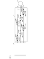
- FIG. 1 It is a block diagram which shows the control apparatus of the alternating current rotating machine by Embodiment 1 of this invention.
- FIG. 1 is a diagram showing a configuration of a control device 1 for an AC rotating machine 2 according to Embodiment 1 of the present invention and its surroundings.
- an AC rotating machine 2 and a power source 10 are provided around the control device 1.
- the AC rotating machine 2 may be a generally known one such as a permanent magnet synchronous motor or a brushless motor.
- the control device 1 controls an AC rotating machine (hereinafter also referred to as a motor) 2 having three-phase windings of U, V, and W phases.
- the control device 1 calculates the rotation angle and rotation speed of the motor 2 in the rotation detection means 7 that detects rotation information of the motor 2.
- the control apparatus 1 detects the electric current which flows into each phase of the motor 2 with the electric current detectors CU, CV, and CW.
- the control device 1 determines a three-phase voltage command according to a current command (also referred to as a q-axis current command) corresponding to a target value of the output torque of the motor 2, a detected current of each phase of the motor 2, and a rotation angle.
- the switching element control means 3 includes means 31 and switching element drive means 32 that PWM modulates the three-phase voltage command from the current control means 31 and instructs the power converter 4 to perform a switching operation. Also, by receiving a switching operation signal from the switching element driving means 32, the chopper control of the switching elements UP, UN, VP, VN, WP, and WN made of MOS-FETs is realized, and power is supplied from the power supply 10 to each phase of the motor 2. A power converter 4 to be supplied is provided.
- the current control means 31 can determine the three-phase voltage command according to the current command and the detected current of each phase of the motor 2, and the motor rotation angle is not necessarily required.
- the motor 2 generates torque by the current flowing from the power converter 4 to each phase of the motor 2.
- the current detectors CU, CV, and CW are arranged in series with the switching elements UP, UN, VP, VN, WP, and WN of the respective phases.
- the current detectors CU, CV, CW are arranged in series on the ground side of the lower switching elements UN, VN, WN.
- diodes DUP, DUN, DVP, DVN, DWP, and DWN are arranged in parallel to the switching elements UP, UN, VP, VN, WP, and WN, respectively. This is generally arranged for the purpose of protecting the switching element.
- the control apparatus 1 is provided with the abnormality determination means 9 which determines a short circuit failure location based on the detection electric current of each phase, and a motor rotation angle.
- an abnormality detection means and a short-circuit location identification means shown in International Publication WO2008 / 129658 may be used.
- This abnormality determination means 9 detects a short-circuit failure occurring in the power converter 4, the AC rotating machine 2, or its electrical connection path, identifies the short-circuit failure location, and outputs the failure location as a failure location signal To do. For example, if the switching element UP is short-circuited, or if the electrical connection path from the switching element UP to the U-phase winding is short-circuited to the bus of the power source, that is, a U-phase power fault, the information UP is Output as.
- short-circuit faults of switching elements UP, UN, VP, VN, WP, WN, and equivalent faults including short-circuit faults between the electrical connection path from the switching element to the motor winding and the power supply bus or ground bus And detect the failure location signal.
- the current control means 31 includes a normal-time current control means used in a normal state where no failure has occurred and an abnormal-time current means used in the event of a failure.
- the normal time control means may be constituted by a known device such as dq control, and detailed description thereof is omitted.
- the abnormal current control means switches the control configuration in accordance with the failure state or rotation information and performs control to generate a voltage command optimal for the failure or rotation state.
- the switch 5 is arranged on each phase wiring that connects the windings of the power converter 4 and the AC rotating machine 2, and for each phase, the switching devices UR, VR, WR made of MOS-FETs, It is composed of diodes DUR, DVR, DWR provided in parallel with the switching elements UR, VR, WR. That is, the switch according to the present embodiment is an electronic switch composed of electronic elements. Compared to a mechanical switch, it is smaller and less expensive.
- the switch control means 6 controls the switch 5 according to the failure location signal and the rotation information, and generates an open or close command to the switch elements UR, VR, WR of each phase, and at the time of failure
- the opening and closing of each open / close element UR, VR, WR is controlled to generate an optimum torque.
- the U phase of the motor wiring or the U phase of the power converter wiring, or the AC rotating machine and the power converter are connected.
- the U phase of the wiring is short-circuited to the wiring connected to the negative potential (also referred to as ground) of the power supply, or the U-phase lower switching element UN is short-circuited, that is, when a U-phase ground fault occurs explain.
- the output torque when all phase switches are closed when the U-phase lower side is short-circuited will be described.
- the state in which the switch 5, that is, the switching elements UR, VR and WR of all phases is closed is referred to as mode I.
- the torque at this time is divided into a region where the power running torque can be output and a region where the brake torque is generated.
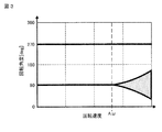
- FIG. 19 of Patent Document 3 above at low speed rotation, the brake torque can be made substantially zero as shown in (a), but at high speed rotation, the brake torque increases as shown in (b).
- the angle range in which the brake torque is generated is also widened. This phenomenon has characteristics as shown in FIG. That is, FIG. 2 shows an area where the dot display area is the brake torque and the other white area is the power running torque with respect to the rotation angle and rotation speed of the motor.
- the output torque when only the failed phase that is, the U-phase switch is opened and the others are closed will be described.
- the state in which only the faulty phase switch is opened is referred to as mode II. At this time, the state is substantially close to the U-phase open state.
- the diode DUR connected in parallel with the open / close element UR becomes conductive when the voltage on the motor side of the diode becomes lower than the ground, and thus is not completely in the U-phase open state.
- the torque at this time will be described with reference to FIG.
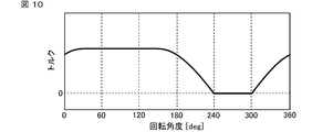
- the output torque at this time is close to the U-phase open state, and the torque becomes zero at 90 degrees and 270 degrees indicated by thick solid lines.
- the waveform at that time is as shown in FIG. 4 as described above. Since the diode DUR conducts during high-speed rotation, a brake torque is generated in the dot display area or a current is generated in the fault phase.
- the white area other than the thick solid line and the dot display area is an area where power running torque is possible.
- Mode III A state in which all-phase switches are opened.
- Mode I All-phase switches are closed
- Mode II Only the fault-phase switches are open, others are closed
- Mode III All-phase switches are opened
- the abnormality determination unit 9 supplies a failure location signal “the U-phase lower side is abnormal” to the switching element control unit 3 and the switch control unit 6.
- the switch control means 6 is configured as shown in FIG. 7, and the map selection means 61 selects a map according to the failure location signal.
- the map is a relationship diagram (also referred to as a torque region map) showing a region of powering torque with respect to the rotation angle and the rotation speed as shown in FIG. 2 described above, and is implemented using a table or the like. It ’s fine.
- FIG. 2 shows the mode I at the time of the U-phase lower side failure, that is, the state in which all the phase switches are closed. In the case of the U-phase upper side failure, the shape is inverted 180 degrees as shown in FIG.
- the area determination unit 62 refers to the map selected by the map selection unit according to the rotation angle and the rotation speed, and instructs the opening / closing command unit to switch between mode I, mode II, and mode III. Pass the mode command.
- FIG. 2 which is the torque region map of mode I
- mode I when the operating point of the rotation angle and the rotation speed is in the power running possible region of the white part, mode I, that is, all-phase switching A mode command is generated so that the device is closed.
- FIG. 2 which is the torque area map of mode I
- the switch is opened only in the mode II, that is, the fault phase. A mode command is generated.
- the switching command means 63 that has received the mode command closes all the phase switches when the mode command is mode I, and the failure phase, that is, the U phase when the mode command is mode II. In the case of mode III, all phase switches are opened. In this example, mode III is not used.
- the switching element control means 3 uses, for example, a control method such as an abnormal current control means in the case where a short-circuit fault of the switching element or a short-circuit fault occurs in one phase shown in Patent Document 2. That's fine.
- This abnormal-time current control means stops driving the abnormal phase switching element in the power converter 4 in the OFF state, and continues control with the remaining two normal phases. And an abnormal voltage command is generated according to a value obtained by adding and subtracting the current deviation of the normal phase and the current deviation of the abnormal phase.
- a control means such as an abnormal current control means shown in Japanese Patent No. 4498353 may be used.
- This abnormal current control means stops driving the abnormal phase switching element in the power converter 4 in the OFF state, and continues the control with the remaining two normal phases.
- the voltage command for each phase is generated and output as an abnormal voltage command so as to satisfy the equilibrium condition that the sum of the voltage commands for each phase is zero, and the phase current command is a cosine related to the rotation angle.
- the phase current command is calculated according to the rotation direction so that the phase current command increases as the angle approaches zero. Control suitable for each fault location can be realized.
- the map selection means 61 selects the torque region map of mode I.
- the map of mode II may be selected. In that case, if there is a rotation operating point in the area of the 90-degree thick line and dot display in mode II and the vicinity thereof, the same effect as described above can be obtained by instructing mode I and instructing mode II elsewhere. can get.
- the U phase of the motor wiring, the U phase of the power converter wiring, or the U phase of the wiring connecting the AC rotating machine and the power converter is short-circuited to the wiring connected to the positive potential of the power supply (also referred to as power supply voltage).
- the power supply also referred to as power supply voltage.
- the output torque when the all-phase switch is closed that is, the mode I of the U phase upper side failure is as shown in FIG.
- the dot display area indicates the area where the brake torque is obtained
- the other white area indicates the area where the power running torque is obtained.
- the dot display area is an area where the diode DUR is conducted, and either a brake torque is generated or a current is generated in the failure phase.
- the white area other than the thick solid line and the dot display area is an area where a power running torque is possible without passing a current through the failure phase.
- the abnormality determination unit 9 supplies a failure point signal “the U-phase upper side is abnormal” to the switching element control unit 3 and the switch control unit 6.
- the map selection means 61 selects the torque region map (FIG. 5) of the mode I of the U phase upper fault with all phase switches closed.
- the mode I that is, the state where all the phase switches are closed
- FIG. 5 which is the torque region map of mode I
- the mode III when the operating point of the rotation angle and the rotation speed is in the brake torque region of the dot display portion, the mode III, that is, the state where the all-phase switch is opened. Generate a mode command.
- the switching element control means does not require any particular operation, but all the switching elements may be turned off.
- the control device for an AC rotating machine includes a plurality of switching elements connected to the AC rotating machine, a power converter that applies a voltage to the AC rotating machine, an AC rotating machine, A power converter, an AC rotating machine, comprising: a switch that opens and closes an electrical connection path of the power converter; a switching element control unit that controls opening and closing of the switching element; and a switch control unit that controls opening and closing of the switch.
- the switch control means is configured to control the opening and closing of the switch according to the rotation information, so that the power converter, the AC rotating machine, Or, when a failure occurs in the electrical connection path, it is possible to eliminate the brake torque and obtain a power running torque of zero or more in an operation region where the brake torque is likely to be generated.
- the closed in accordance with the rotating state it is possible to reduce the angle at which the torque becomes zero. Further, not only can the output torque be improved, but there is no need to make redundant by providing two windings and power converters, and the cost can be reduced without increasing the size.
- the switching element control means is configured to control the voltage by switching the switching of the switching element.
- the switch control means is configured to repeat the opening and closing of the phase in which the fault has occurred and the other phases to maintain the connection state, so the fault phase is used only in the rotation region where no brake torque is generated, and in the other rotation regions Control can be performed in two phases without failure, and output torque can be improved.
- the switch control means is configured to repeat the opening and closing of all phases, use all phases only in the rotation region where no brake torque is generated, and block all phases in other rotation regions to eliminate the brake torque. Output torque can be improved.
- the switch control means is configured to open the switch of the phase in which the failure has occurred when powering is impossible with all the switches closed, the faulty phase is used only in the rotation region where powering is possible, In other rotation regions, control can be performed in two phases without failure, and output torque can be improved.
- the switch control means is configured to open all the switches when powering is impossible with all the switches closed, so all the phases are used only in the rotation region where powering is possible, and the other rotations In the region, the brake torque can be eliminated by blocking all phases, and the output torque can be improved.
- the switch is an electronic switch that cuts off a current in one direction, that is, a diode, and when a failure occurs in the power converter, the AC rotating machine, or the path between them, the switch Since the control means is configured to repeat opening and closing of the switch, The size can be made smaller than that using a mechanical switch, and the output torque can be improved.
- the diode of the switch is arranged in the direction from the power converter to the motor.
- the diode may be arranged in the reverse direction. If the operation is switched so that the switch control means is also symmetric, the same effect can be obtained.
- the switch 5 is configured by an electronic switch using electronic elements such as a MOS-FET and a diode.
- the switch 5 is configured by a mechanical switch, The difference in the operation of the switch control means at the time of a power fault including a short circuit fault of the upper switching element is the difference from the first embodiment, and the other is the same.
- FIG. 11 shows the control device 1 of the present embodiment. Since the switch is configured mechanically, it is not necessary to have a diode in parallel with the switch. Therefore, by opening the switch, bidirectional current can be cut off.
- a U-phase short-circuit fault will be described as a representative.
- the mode I in which all the phases of the switch are closed is the same as that in the first embodiment.
- Mode II which opens the switch only for the failed U phase, has the same characteristics both in the case of a power fault including a short circuit fault in the upper switching element and in a ground fault including a short circuit fault in the lower switching element of the U phase.
- the torque becomes zero only at the thick solid line portions of 90 and 270 degrees, and the power running torque is possible in other cases. This can be understood from the fact that the torque at the time of opening one phase is obtained because one phase of the mechanical switch is opened. In terms of the waveform, it is as shown in FIG.
- the abnormality determination unit 9 supplies a failure point signal “the U-phase upper side is abnormal” to the switching element control unit 3 and the switch control unit 6.
- the map selection means 61 selects the torque region map (FIG. 5) of the mode I of the U phase upper fault in which all the phases of the switch 5 are closed.
- mode I that is, the state in which all phases of the switch 5 are closed
- a mode command is generated so that
- FIG. 5 which is the torque area map of mode I, when the operating point of the rotation angle and the rotation speed is in the brake torque area of the dot display portion, the mode II, that is, the state where the failure phase switch is opened.
- a mode command is generated.
- the switch is capable of interrupting bidirectional current, and when a failure occurs in the power converter, the AC rotating machine, or the path between them, the switch control means opens the switch. Since the closing is repeated, the region where the torque is zero can be limited to one point, and the output torque can be improved.
- the switch 5 is a mechanical switch.
- the electronic switches such as the MOS-FET and the diode are arranged in each phase so that the directions are reversed.
- the other points are the same in that they are doubled in series.
- FIG. 14 shows the control device 1 of the present embodiment. Since the electronic switch is doubled in both directions, the bidirectional current can be cut off by opening the switch. That is, the same effect as that of the second embodiment using the mechanical switch can be obtained.
- FIG. 15 a configuration as shown in FIG. 15 may be used. Since an electronic switch is arranged in series with the upper switching element, bidirectional current can be cut off in the case of an upper short-circuit fault, and only the fault phase of mode II is cut off as in FIG. Can be realized. Therefore, a similar effect can be obtained.
- Embodiment 4 FIG.
- the operation of the switch control means at the time of a ground fault including a short-circuit failure of the lower switching element is different from that of the first embodiment, and the others are the same.
- the mode selection torque region map is selected by the map selection means.
- the mode II is used when a ground fault including a short-circuit fault of the lower switching element occurs (FIG. 3). ).
- the area determination means 62 When there is a rotational operation point in the dot display area of the torque area map of mode II, the area determination means 62 generates a mode instruction so as to instruct mode III and otherwise instruct mode II.
- the switch control means is configured so that the phase in which the failure occurs is kept open and the other phases are repeatedly opened and closed. Therefore, the output torque can be improved while the switch of the failed phase remains open.
- the switch control means is configured to open all the switches when power failure is impossible with the phase in which the fault has occurred open. In all other rotation regions, all phases can be shut off to eliminate the brake torque, and the output torque can be improved.
- the switch control means 6 generates a mode command based on two pieces of rotation information, that is, a rotation angle and a rotation speed.
- it is configured to generate a mode command using only the rotation speed as rotation information, and not configured to open and close the switch individually for each phase, but simply configured to open and close all phases at the same time. This is different from the first embodiment in that the other points are the same.
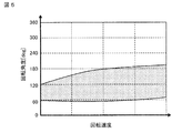
- the brake torque generated in the dot display portion in the torque region map of mode I at the time of U-phase failure increases as the rotational speed increases, and the relationship is as shown in FIG. According to FIG. 16, in the region where the rotational speed is smaller than ⁇ B, the brake torque is as small as half or less of the maximum value. Therefore, by using mode I in the low speed range and using mode III in the high speed range, it is possible to output almost the power running torque in the low speed range, and in the high speed range, the braking is prevented from becoming dominant and the torque is reduced to zero. it can.
- the map selection means selects FIG. 16, and the area determination means compares the rotation speed with the rotation speed threshold value ⁇ B. When the rotation speed is smaller, command the mode I, and when the rotation speed is larger. A mode command is generated to command mode III.
- the rotation information is only the rotation speed of the AC rotating machine, there is an effect that the output torque can be improved while simplifying the configuration of the switch control means and the configuration of the switch.
- the switch control unit 6 generates a mode command based on the rotation speed detected by the rotation detection unit 7, but the rotation detection unit 7 May be configured to estimate or detect the induced voltage of the AC rotating machine 2, and may be handled in the same manner as the rotational speed by multiplying the induced voltage by a gain.
- the induced voltage may be calculated using a generally known method such as using a current deviation or a voltage. Since the induced voltage and the rotation speed tend to be approximately proportional, the same effect as described above can be obtained.
- Embodiment 6 FIG.
- the switch control means 6 generates a mode command based on two pieces of rotation information, that is, a rotation angle and a rotation speed.
- the present embodiment is the same as the first embodiment except that the mode command is generated using only the rotation angle as the rotation information.
- the region determination means 62 determines whether the brake torque region or the power running region is on the torque region map in mode I based on the rotation speed and the rotation angle. Then, based on only the rotation angle, the mode command is selected as shown at the right end of FIG. In FIG. 17, the angle region in which the mode II or the mode III is set is determined so as to be in contact with and include the brake torque region indicated by dots.
- the map selection means 61 selects (a) in FIG. 17, and the area determination means comes into contact with and includes the brake torque area indicated by dots.
- the mode II is instructed, and in other areas, the mode instruction is instructed to instruct mode I.
- the map selection means 61 selects (b) of FIG. 17, and the area determination means contacts and includes the brake torque area indicated by dots.
- mode III is commanded, and in other regions, mode command is generated so as to command mode I.
- Embodiment 7 FIG.
- the switch 5 is configured to include a component capable of interrupting bidirectional current in each phase.
- the switch control means 6 is different from the second and third embodiments in that the mode I and the mode III are switched without using the mode II, but the other points are the same.
- the switch 5 is a mechanical type capable of interrupting the bidirectional current shown in FIG. 18 (a), or FIG. 18 (b) an electronic type doubled so that the directions of the diodes face each other only in two phases. Configure to include. Even if it is only in two phases, if all are opened, the current in three phases is cut off.
- the switch control means 6 selects the mode I torque region map by the map selection means 61 as in the second and third embodiments, and determines whether or not the rotation state is in the brake torque region indicated by dots. When in the brake torque region, a mode command is generated so as to enter mode III.
- the switch control means 6 is configured to generate a mode command using only the rotation speed as the rotation information, and is configured to open and close all phases of the switch 5 simultaneously,
- the switching element control means 3 is configured to improve the output torque by the abnormal current control means.
- the switching element control means 3 stops all the switching elements. To be configured. Others are the same.
- the switch control means controls opening and closing of the switch according to the rotation information, and the switching element control means Since the switching element is configured to be fixed in the open state, it is possible to notify the failure while the output torque is substantially zero.
- FIG. 19 shows Embodiment 9 of the present invention, and shows an example in which the control device for an AC rotating machine shown in the above-described embodiments is applied to an electric power steering device for an automobile.
- FIG. 19 is a schematic configuration diagram of an electric power steering apparatus according to Embodiment 9 of the present invention.
- a steering force applied to the steering wheel 101 by a driver passes through the steering shaft 103 and is transmitted to the rack via the rack and pinion gear 104 to steer the wheels 105.
- the AC rotating machine 2 is connected to the steering shaft 103 via the motor reduction gear 102.
- Torque (hereinafter also referred to as auxiliary force) generated by the AC rotating machine 2 is transmitted to the steering shaft 103 via the motor reduction gear 102, and reduces the steering force applied by the driver during steering.
- the torque detection means 106 detects, as an output torque, a mixed torque of the steering torque applied to the steering shaft 103 and the torque generated by the AC rotating machine 2 when the driver steers the steering wheel 101.
- the control device 1 determines the direction and magnitude of the auxiliary force applied by the AC rotary machine 2 according to the output torque detected by the torque detection means 106, and controls the current flowing through the rotary machine to generate this auxiliary force. To do.
- the control device 1 uses any one of the above-described embodiments.
- a current command generation unit 107 that calculates a current command based on the output torque detected by the torque detection unit 106 is provided.
- the switch control means Since the opening and closing of the vehicle are controlled according to the rotation information, the brake torque can be eliminated, the output torque can be improved, and the driver can feel a sense of incongruity.
- the switch is arranged on the power converter side of the motor.
- the switch may be arranged inside the motor, for example, near the neutral point of the winding. Since they are equivalent, the same action as described above can be obtained.
- the embodiments can be freely combined within the scope of the invention, and the embodiments can be appropriately changed or omitted.
Landscapes
- Engineering & Computer Science (AREA)
- Power Engineering (AREA)
- Chemical & Material Sciences (AREA)
- Combustion & Propulsion (AREA)
- Transportation (AREA)
- Mechanical Engineering (AREA)
- Control Of Ac Motors In General (AREA)
- Operating, Guiding And Securing Of Roll- Type Closing Members (AREA)
- Control Of Electric Motors In General (AREA)
Abstract
Priority Applications (5)
| Application Number | Priority Date | Filing Date | Title |
|---|---|---|---|
| US15/107,217 US9876458B2 (en) | 2014-03-19 | 2014-03-19 | Control device for AC rotating machine and electric power steering device |
| JP2016508396A JP6177426B2 (ja) | 2014-03-19 | 2014-03-19 | 交流回転機の制御装置および電動パワーステアリング装置 |
| EP14886589.2A EP3121957A4 (fr) | 2014-03-19 | 2014-03-19 | Dispositif de commande de machine rotative ca et dispositif de direction assistée électrique |
| CN201480077174.6A CN106105020B (zh) | 2014-03-19 | 2014-03-19 | 交流旋转电机的控制装置及电动助力转向装置 |
| PCT/JP2014/057546 WO2015140960A1 (fr) | 2014-03-19 | 2014-03-19 | Dispositif de commande de machine rotative ca et dispositif de direction assistée électrique |
Applications Claiming Priority (1)
| Application Number | Priority Date | Filing Date | Title |
|---|---|---|---|
| PCT/JP2014/057546 WO2015140960A1 (fr) | 2014-03-19 | 2014-03-19 | Dispositif de commande de machine rotative ca et dispositif de direction assistée électrique |
Publications (1)
| Publication Number | Publication Date |
|---|---|
| WO2015140960A1 true WO2015140960A1 (fr) | 2015-09-24 |
Family
ID=54143967
Family Applications (1)
| Application Number | Title | Priority Date | Filing Date |
|---|---|---|---|
| PCT/JP2014/057546 WO2015140960A1 (fr) | 2014-03-19 | 2014-03-19 | Dispositif de commande de machine rotative ca et dispositif de direction assistée électrique |
Country Status (5)
| Country | Link |
|---|---|
| US (1) | US9876458B2 (fr) |
| EP (1) | EP3121957A4 (fr) |
| JP (1) | JP6177426B2 (fr) |
| CN (1) | CN106105020B (fr) |
| WO (1) | WO2015140960A1 (fr) |
Cited By (1)
| Publication number | Priority date | Publication date | Assignee | Title |
|---|---|---|---|---|
| JP2017204942A (ja) * | 2016-05-12 | 2017-11-16 | オムロンオートモーティブエレクトロニクス株式会社 | モータ制御装置 |
Families Citing this family (5)
| Publication number | Priority date | Publication date | Assignee | Title |
|---|---|---|---|---|
| JP5999291B1 (ja) * | 2014-12-25 | 2016-09-28 | 日本精工株式会社 | 電動パワーステアリング装置 |
| DE102017211219A1 (de) * | 2017-06-30 | 2019-01-03 | Volkswagen Aktiengesellschaft | Verfahren und Vorrichtung zum Betreiben einer elektrischen Maschine, insbesondere eines Lenkunterstützungsantriebs |
| WO2019066021A1 (fr) * | 2017-09-29 | 2019-04-04 | アイシン・エィ・ダブリュ株式会社 | Dispositif de commande d'onduleur |
| KR20210077250A (ko) * | 2019-12-17 | 2021-06-25 | 주식회사 만도 | 이중 권선형 모터 제어장치 및 방법 |
| CN113581280B (zh) * | 2021-08-06 | 2023-07-21 | 中汽创智科技有限公司 | 一种基于六相电机的转向系统控制电路及控制方法 |
Citations (6)
| Publication number | Priority date | Publication date | Assignee | Title |
|---|---|---|---|---|
| WO2005091488A1 (fr) * | 2004-03-19 | 2005-09-29 | Mitsubishi Denki Kabushiki Kaisha | Régulateur de moteur |
| JP2010254128A (ja) * | 2009-04-24 | 2010-11-11 | Denso Corp | 車載電力変換装置 |
| JP2011051481A (ja) * | 2009-09-02 | 2011-03-17 | Nsk Ltd | 電動パワーステアリング装置 |
| WO2011048683A1 (fr) * | 2009-10-22 | 2011-04-28 | 三菱電機株式会社 | Appareil de conversion de courant pour une voiture électrique |
| WO2012160092A2 (fr) * | 2011-05-24 | 2012-11-29 | Continental Automotive Gmbh | Procédé et dispositif permettant de faire fonctionner un moteur sans balais |
| JP2013141945A (ja) * | 2012-01-12 | 2013-07-22 | Jtekt Corp | 電動パワーステアリング装置 |
Family Cites Families (12)
| Publication number | Priority date | Publication date | Assignee | Title |
|---|---|---|---|---|
| JP2861680B2 (ja) * | 1992-10-13 | 1999-02-24 | 株式会社日立製作所 | 電気自動車用故障検出法及びそれを用いたフェールセイフ制御方法 |
| DE50107806D1 (de) * | 2000-09-20 | 2005-12-01 | Thyssenkrupp Presta Steertec | Zusätzliche Rückfallebene bei Ausfall von Winkelsensoren für "Steer-by-wire"-Systeme ohne mechanische/hydraulische Rückfallverbindung und Verfahren zur Ermittlung des Verdrehwinkels der Lenkhandhabe einer Servolenkung |
| JP4701767B2 (ja) * | 2005-03-18 | 2011-06-15 | トヨタ自動車株式会社 | 電源装置 |
| US7990093B2 (en) * | 2006-04-20 | 2011-08-02 | Mitsubishi Electric Corporation | Electric motor control apparatus |
| CN101595633B (zh) | 2007-04-16 | 2012-06-06 | 三菱电机株式会社 | 电动机控制装置 |
| JP2009035155A (ja) | 2007-08-02 | 2009-02-19 | Denso Corp | 電動パワーステアリング装置 |
| JP5014034B2 (ja) * | 2007-09-12 | 2012-08-29 | オムロンオートモーティブエレクトロニクス株式会社 | 多相交流モータ駆動装置 |
| DE102008021854A1 (de) * | 2008-05-02 | 2009-11-05 | Volkswagen Ag | Vorrichtung und Verfahren zur Überwachung möglicher Fehler in einer technischen Einrichtung, insbesondere Servo-Lenksystem |
| DE102010001241A1 (de) * | 2009-04-01 | 2010-10-07 | Robert Bosch Gmbh | Elektronisch kommutierter Elektromotor mit einer Notlaufeigenschaft |
| JP4831503B2 (ja) | 2009-09-30 | 2011-12-07 | 株式会社デンソー | 多相回転機の制御装置、および、これを用いた電動パワーステアリング装置 |
| GB201013106D0 (en) * | 2010-08-04 | 2010-09-22 | Trw Ltd | Diagnostic method for electric power steering system |
| CN104185950B (zh) * | 2012-03-22 | 2016-12-07 | 日立汽车系统株式会社 | 电力变换装置、电动动力转向系统、电动汽车、电子控制节流阀、电动制动器 |
-
2014
- 2014-03-19 US US15/107,217 patent/US9876458B2/en active Active
- 2014-03-19 JP JP2016508396A patent/JP6177426B2/ja not_active Expired - Fee Related
- 2014-03-19 WO PCT/JP2014/057546 patent/WO2015140960A1/fr active Application Filing
- 2014-03-19 CN CN201480077174.6A patent/CN106105020B/zh active Active
- 2014-03-19 EP EP14886589.2A patent/EP3121957A4/fr not_active Withdrawn
Patent Citations (6)
| Publication number | Priority date | Publication date | Assignee | Title |
|---|---|---|---|---|
| WO2005091488A1 (fr) * | 2004-03-19 | 2005-09-29 | Mitsubishi Denki Kabushiki Kaisha | Régulateur de moteur |
| JP2010254128A (ja) * | 2009-04-24 | 2010-11-11 | Denso Corp | 車載電力変換装置 |
| JP2011051481A (ja) * | 2009-09-02 | 2011-03-17 | Nsk Ltd | 電動パワーステアリング装置 |
| WO2011048683A1 (fr) * | 2009-10-22 | 2011-04-28 | 三菱電機株式会社 | Appareil de conversion de courant pour une voiture électrique |
| WO2012160092A2 (fr) * | 2011-05-24 | 2012-11-29 | Continental Automotive Gmbh | Procédé et dispositif permettant de faire fonctionner un moteur sans balais |
| JP2013141945A (ja) * | 2012-01-12 | 2013-07-22 | Jtekt Corp | 電動パワーステアリング装置 |
Non-Patent Citations (1)
| Title |
|---|
| See also references of EP3121957A4 * |
Cited By (3)
| Publication number | Priority date | Publication date | Assignee | Title |
|---|---|---|---|---|
| JP2017204942A (ja) * | 2016-05-12 | 2017-11-16 | オムロンオートモーティブエレクトロニクス株式会社 | モータ制御装置 |
| CN107370443A (zh) * | 2016-05-12 | 2017-11-21 | 欧姆龙汽车电子株式会社 | 电动机控制装置 |
| CN107370443B (zh) * | 2016-05-12 | 2022-02-25 | 欧姆龙汽车电子株式会社 | 电动机控制装置 |
Also Published As
| Publication number | Publication date |
|---|---|
| JPWO2015140960A1 (ja) | 2017-04-06 |
| CN106105020A (zh) | 2016-11-09 |
| CN106105020B (zh) | 2019-03-08 |
| EP3121957A1 (fr) | 2017-01-25 |
| EP3121957A4 (fr) | 2018-03-21 |
| US20170033724A1 (en) | 2017-02-02 |
| JP6177426B2 (ja) | 2017-08-09 |
| US9876458B2 (en) | 2018-01-23 |
Similar Documents
| Publication | Publication Date | Title |
|---|---|---|
| JP6177426B2 (ja) | 交流回転機の制御装置および電動パワーステアリング装置 | |
| US8981704B2 (en) | Motor controller and electric power steering device using the same | |
| JP5229645B2 (ja) | 電動機駆動装置、および、これを用いた電動パワーステアリング装置 | |
| US8232752B2 (en) | Electric motor control apparatus | |
| JP5282376B2 (ja) | 電動パワーステアリング装置 | |
| US7990093B2 (en) | Electric motor control apparatus | |
| JP5569626B1 (ja) | モータ制御装置、これを使用した電動パワーステアリング装置及び車両 | |
| JP5195888B2 (ja) | 電動機駆動装置、および、これを用いた電動パワーステアリング装置 | |
| JP5579495B2 (ja) | モータ駆動装置 | |
| JP5229644B2 (ja) | 電動機駆動装置、および、これを用いた電動パワーステアリング装置 | |
| WO2014141342A1 (fr) | Dispositif de régulation de moteur et dispositif d'attaque à alimentation électrique et véhicule l'utilisant | |
| WO2014136166A1 (fr) | Dispositif d'alimentation de moteur, dispositif de direction à assistance électrique l'utilisant, et véhicule | |
| EP3193443B1 (fr) | Dispositif d'onduleur pour entraîner un moteur à courant alternatif polyphasé | |
| JP2007295658A (ja) | モータ制御装置及びこれを用いた電動パワーステアリング制御装置 | |
| EP2530830A1 (fr) | Système d'entraînement de moteur, procédé de contrôle du système d'entraînement de moteur, et dispositif mobile | |
| US8886411B2 (en) | Power steering system | |
| US20180191283A1 (en) | Motor Control Device and Electric Power Steering Device Mounting the Same | |
| JP4778248B2 (ja) | 電動パワーステアリング装置 | |
| US11205988B2 (en) | Motor control device | |
| US11987298B2 (en) | Motor control device and steering system having the same | |
| JP2010137627A (ja) | 電動パワーステアリング装置 | |
| JP5527182B2 (ja) | 電動パワーステアリング装置 |
Legal Events
| Date | Code | Title | Description |
|---|---|---|---|
| 121 | Ep: the epo has been informed by wipo that ep was designated in this application |
Ref document number: 14886589 Country of ref document: EP Kind code of ref document: A1 |
|
| ENP | Entry into the national phase |
Ref document number: 2016508396 Country of ref document: JP Kind code of ref document: A |
|
| WWE | Wipo information: entry into national phase |
Ref document number: 15107217 Country of ref document: US |
|
| REEP | Request for entry into the european phase |
Ref document number: 2014886589 Country of ref document: EP |
|
| WWE | Wipo information: entry into national phase |
Ref document number: 2014886589 Country of ref document: EP |
|
| NENP | Non-entry into the national phase |
Ref country code: DE |