WO2015140957A1 - 靴のアッパー - Google Patents
靴のアッパー Download PDFInfo
- Publication number
- WO2015140957A1 WO2015140957A1 PCT/JP2014/057522 JP2014057522W WO2015140957A1 WO 2015140957 A1 WO2015140957 A1 WO 2015140957A1 JP 2014057522 W JP2014057522 W JP 2014057522W WO 2015140957 A1 WO2015140957 A1 WO 2015140957A1
- Authority
- WO
- WIPO (PCT)
- Prior art keywords
- upper portion
- foot
- dividing line
- covers
- phalanx
- Prior art date
Links
Images


Classifications
-
- A—HUMAN NECESSITIES
- A43—FOOTWEAR
- A43B—CHARACTERISTIC FEATURES OF FOOTWEAR; PARTS OF FOOTWEAR
- A43B23/00—Uppers; Boot legs; Stiffeners; Other single parts of footwear
- A43B23/02—Uppers; Boot legs
- A43B23/0245—Uppers; Boot legs characterised by the constructive form
- A43B23/0265—Uppers; Boot legs characterised by the constructive form having different properties in different directions
- A43B23/027—Uppers; Boot legs characterised by the constructive form having different properties in different directions with a part of the upper particularly flexible, e.g. permitting articulation or torsion
-
- A—HUMAN NECESSITIES
- A43—FOOTWEAR
- A43B—CHARACTERISTIC FEATURES OF FOOTWEAR; PARTS OF FOOTWEAR
- A43B23/00—Uppers; Boot legs; Stiffeners; Other single parts of footwear
- A43B23/02—Uppers; Boot legs
- A43B23/0205—Uppers; Boot legs characterised by the material
- A43B23/024—Different layers of the same material
-
- A—HUMAN NECESSITIES
- A43—FOOTWEAR
- A43B—CHARACTERISTIC FEATURES OF FOOTWEAR; PARTS OF FOOTWEAR
- A43B23/00—Uppers; Boot legs; Stiffeners; Other single parts of footwear
- A43B23/02—Uppers; Boot legs
- A43B23/0245—Uppers; Boot legs characterised by the constructive form
-
- A—HUMAN NECESSITIES
- A43—FOOTWEAR
- A43B—CHARACTERISTIC FEATURES OF FOOTWEAR; PARTS OF FOOTWEAR
- A43B23/00—Uppers; Boot legs; Stiffeners; Other single parts of footwear
- A43B23/02—Uppers; Boot legs
- A43B23/0245—Uppers; Boot legs characterised by the constructive form
- A43B23/0295—Pieced uppers
-
- A—HUMAN NECESSITIES
- A43—FOOTWEAR
- A43C—FASTENINGS OR ATTACHMENTS OF FOOTWEAR; LACES IN GENERAL
- A43C1/00—Shoe lacing fastenings
Definitions
- the present invention relates to a shoe upper.
- the upper with polyurethane or the like As a structure for suppressing the “shelf drop”, it is conceivable to increase the rigidity of the upper with polyurethane or the like outside the front foot.
- the upper with high rigidity causes buckling in which the upper is locally bent at the time of dorsiflexion of the foot, and the along the foot tends to deteriorate.
- an object of the present invention is to provide an upper of a shoe that can cope with various wearers and movements and can achieve both goodness along the foot and suppression of “shelf drop”.
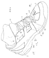
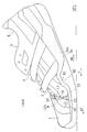
- the upper of the present invention includes a first upper portion 1 that covers the outer side L of the toe, A second upper portion 2 that covers and supports the side surface of the small ball O5 on the outer surface; In a standing position and in a dorsiflexed state where the foot is dorsiflexed, the first upper portion 1 and the second upper portion 2 overlap with each other on the outer surface, and an overlapping region ⁇ that does not restrain each other; The front end 20 of the second upper portion 2 is displaced with respect to the first upper portion 1 as the foot is bent back from the stationary standing position, so that the area of the overlapping region ⁇ is increased.
- the upper portion 1 and the second upper portion 2 are provided with a dividing line L1 that is divided from each other,
- the position in the front-rear direction Y of the foot at the lower end 11 of the dividing line L1 is set to the front YF from the midfoot phalanx joint MP5 of the gavel and the rear YR from the tip of the fourth heel.
- a dividing line L1 is provided on the outer side L of the forefoot.
- the position in the front-rear direction Y of the foot at the lower end 11 of the dividing line L1 is set to the rear YR from the tip of the fourth heel. Since the buckling of the upper U occurs at the rear R from the tip of the fourth rod, the second upper portion 2 of the upper U having the dividing line is easily bent along with the deformation of the foot when the foot is bent back. Therefore, improvement along the foot can be expected.
- the position of the lower end 11 of the dividing line L1 is set to the front YF with respect to the small foot metatarsal joint MP5. Therefore, the second upper portion 2 supports the small joint MP joint and the front and rear portions thereof. Therefore, “shelf drop” is suppressed.
- the dividing line L1 has a rear end of the first upper portion 1 or a front end 20 of the second upper portion 2 appearing in a line shape on the outer surface.
- the first upper portion 1 and the second upper portion 2 are each formed of a plate-like or fabric-like material having a predetermined thickness, and therefore the dividing line L1 is the rear end surface of the first upper portion 1 or the second upper portion. It means one side of the front end surface of the portion 2 along the surface of the material.
- “foot dorsiflexion” means that a joint in the foot, for example, a metatarsal joint joint or an intercostal joint is dorsiflexed.
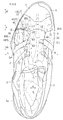
- FIG. 10A is a plan view showing the arrangement of the sensor together with the foot skeleton
- FIG. 10B is a plan view showing an array of areas for analysis in the sensor.
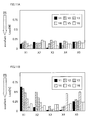
- FIG. 11A is a bar graph showing the force generated in each area in the same example
- FIG. 11B is a bar graph in the case of the comparative example.
- the position in the front-rear direction Y of the foot of the lower end 11 of the dividing line L1 is set to the front YF from the bone bottom of the small phalanx B35 and to the rear YR from the tip of the fourth heel. .
- the position of the dividing line L1 is set to the front YF from the bone bottom of the small phalanx B35.
- the second upper portion 2 supports both the small ball O5 outside the foot and the bone bottom of the small phalanx B35 from the outer surface. Therefore, the effect of suppressing the “shelf drop” will increase.
- the position of the foot of the lower end 11 of the dividing line L1 in the front-rear direction Y is YF forward of the bone bottom of the small phalanx B35 and YR posterior to the distal end of the distal phalange B14 of the fourth heel. Is set to In this case, “shelf drop” is suppressed as described above.
- the dividing line L1 is set in the rear YR from the distal end of the distal phalange B14 of the fourth heel, and further improvement along the foot can be expected.
- the overlap region ⁇ is set in a state in which the front edge portion 21 of the second upper portion 2 is under the first upper portion 1 in the static standing position. In this case, as will be described later, along the foot will be further improved.
- the overlapping state of the upper portions is guided so that the upper portions overlap each other in the overlapping region ⁇ .
- Guide means G is further provided.
- the outer surface of the upper will also bend.
- the dorsiflexion of the MP joints of the second to fourth heels is more dominant than the dorsiflexion of the MP joints of the small heels, and the second upper portion 2 contacts the toes along these dorsiflexions. It may be bent until it is done.
- the second upper portion 2 exerts pressure on the upper surface of the toes more than when standing still.
- the first upper portion 1 is disposed on the upper side of the second upper portion 2, the first upper portion 1 is difficult to bend and hardly presses the upper surface of the toes. As a result, along the foot will be further improved.
- the guide means G includes the overlapping region ⁇ in a state in which the front edge portion 21 of the second upper portion 2 is under the first upper portion 1 in the static standing position.
- the rear edge portion of the first upper portion 1 is disposed on the upper side of the front edge portion 21 of the second upper portion 2 in a stationary position, and the overlapping region ⁇ increases during dorsiflexion, so that the arrangement state is It will be maintained even when bent. Therefore, the improvement along the foot can be easily realized.
- the guide means G further includes a shoe race 4 inserted through a plurality of holes H1 and H2 for passing the upper U.
- a part of the shoelace 4 is between the holes of the first upper portion 1 of the plurality of holes H1 and H2 and the holes of the second upper portion 2 of the plurality of holes H1 and H2. It is arranged below the first upper part 1 and above the second upper part 2.
- the dividing line L1 extends downward from the upper edge 1E of the first upper portion 1 to the lower end 11 and is connected to the opening 6 in front of the foot 5 of the upper U, and from the opening 6 to the outside of the foot. Extending to the lower end 11 toward From the lower end 11 of the dividing line L1 to the upper end S1 of the shoe soles Sm, So, the first upper portion 1 and the second upper portion 2 are connected to each other more firmly in the front-rear direction Y of the foot than the overlapping region ⁇ .
- the upper U further includes a continuous portion 12.
- the outer continuous portions 12 are connected to each other more firmly than the overlapping region ⁇ , so that the effect of suppressing “shelf drop” will be enhanced.
- the outer continuous portion 12 is formed by joining the first upper portion 1 and the second upper portion 2 to each other.
- the 1st upper part 1 and the 2nd upper part 2 are couple
- the inner side further includes a third upper portion 3 that covers and supports the side surface of the main ball O1,
- the bending rigidity of the members constituting the first and second upper parts 1 and 2 is larger than that constituting the third upper part 3.
- the outer surface of the gavel is easily supported by the first and second upper portions 1 and 2 having higher bending rigidity than the third upper portion 3. Therefore, the effect of suppressing the “shelf drop” is increased, and the dorsiflexion operation on the inner side of the foot is difficult to be prevented.
- the inner side further includes a third upper portion 3 that covers and supports the side surface of the main ball O1,
- the third upper portion 3 has an inner continuous portion 32 that covers the inner surface without being divided from the bone bottom of the proximal phalanx B31 of the main shaft to the main ball O1 in the front-rear direction.
- G is further provided,
- the position in the front-rear direction Y of the foot at the lower end 11 of the dividing line L1 is set to the front YF from the bone bottom of the small phalanx B35 and to the rear YR from the tip of the fourth heel.
- the inner side further includes a third upper portion 3 that covers and supports the side surface of the main ball O1
- the bending rigidity of the members constituting the first and second upper portions 1 and 2 is larger than that constituting the third upper portion 3,
- the position in the front-rear direction Y of the foot of the lower end 11 of the dividing line L1 is set to the front YF from the bone bottom of the small phalanx B35 and to the rear YR from the distal end of the fourth phalanx B14. ing.
- the inner side further includes a third upper portion 3 that covers and supports the side surface of the main ball O1
- the bending rigidity of the members constituting the first and second upper portions 2 is larger than that constituting the third upper portion 3,
- the third upper portion 3 has an inner continuous portion 32 that covers the inner side surface and is continuous without being divided from the bone bottom of the proximal phalanx B35 of the main shaft to the main ball O1.
- the support on the outer surface of the gavel and the vicinity of the MP joint of the mother's heel is enhanced. Therefore, the effect of suppressing the “shelf drop” is increased, and the flexible third upper portion 3 makes the dorsiflexion inside the foot smooth.
- the inner side surface includes a third upper portion 3 that covers and supports the toes and the side surfaces of the main ball,
- the dividing line L1 extends downward from the upper edge 1E of the first upper portion 1 to the lower end 11 and continues to the opening 6 in front of the upper wear mouth 5 from the opening 6 toward the outside of the foot.
- the first upper portion 1 defines a front end line L2 of the opening 6;
- a continuous line L3 connecting the dividing line L1 and the front end line L2 extends in the foot width direction X so as to cross the second rib B2 of the foot and the fourth rib B4.
- the continuous line L3 connecting the dividing line L1 and the front end line L2 extends over a wide range from the second rib B2 to the fourth rib B4. Therefore, an increase in the flexibility of the entire upper toe portion can be expected.
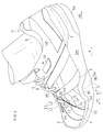
- FIGS. 1 and 2 is, for example, a handball or volleyball shoe, and includes a sole and an upper U.
- the sole includes an outsole So, a midsole Sm, a heel counter 7 and an insole (not shown) that are integrally coupled to each other. 7 to 9, the midsole Sm is provided with irregular small halftone dots.
- An upper U is fixed to the midsole Sm of FIG.
- the outsole So has a ground contact surface.
- the main material is rubber, urethane resin, etc., and the Young's modulus is larger and the bending rigidity is relatively larger than that of the midsole Sm.
- the outsole So made of rubber or the like has a winding portion 80 that reinforces the bone bottom of the proximal phalange B35 of the small heel B5 and the support of the small ball O5 from the outer surface on the outer side L of the foot (FIG. 9).
- the bone bottom refers to a portion of each bone that is close to the posterior joint and bulges slightly thickly, and is also called the proximal bone head.
- the bone head refers to a portion that is slightly thicker and bulges near the front joint in each bone, and is also called a distal head.
- the bone body means a portion between the bone bottom and the bone head, and the thickness generally changes smoothly.
- the upper U includes an interior material U1 and an exterior material U2 with halftone dots.
- the upper U defines a mouth 5 for wrapping the instep and inserting the foot.
- the upper U is tightened by the shoe race 4.
- the interior material U1 is in contact with the upper surface, side surface or rear surface of the foot.
- the interior material U1 is made of a stretchable material such as a mesh or woven fabric, and softly wraps the foot and improves the foot contact.
- the midsole Sm in FIG. 1 is mainly composed of a thermoplastic resin foam disposed on the outsole So, for example, mainly composed of EVA foam, and partly includes other cushioning members such as gel. It may be.
- the midsole Sm is sandwiched between the upper part 80 and the upper U of the outsole So, and covers the bone bottom of the proximal phalanx B35 and the outer side of the small ryukyu O5 in FIG. 81.
- the exterior material U ⁇ b> 2 includes a first upper portion 1, a second upper portion 2, and a third upper portion 3.
- a material that hardly stretches or substantially does not stretch such as a non-foamed plate material of artificial leather, synthetic leather, or thermoplastic resin, is used.
- the through-hole U0 may be provided in the exterior material U2, and the mesh material which comprises the interior material U1 from the through-hole U0 may be exposed.
- the material that is difficult to stretch means a material that is difficult to stretch, such as artificial leather, compared to the interior material U1.
- the material that does not substantially stretch means a material such as the plate material that hardly undergoes elongation during walking or running.
- the first and second upper portions 1 and 2 have small fine dots.
- the first upper portion 1 covers the outer side L of the toe.
- the second upper portion 2 covers and supports the side surface of the small ball O5 at the winding portions 80 and 81 on the outer side surface. That is, on the side surface of the small ball O5, the interior material U1, the exterior material U2 (second upper portion 2), the midsole Sm, and the sole So of FIG. 1 are laminated.
- the first and second upper portions 1 and 2 are made of, for example, a non-foamed plate material (mesh shape and / or flat plate shape) of thermoplastic resin.
- the bending rigidity of the plate material constituting the first and second upper portions 1 and 2 is larger than that constituting the third upper portion 3.
- the third upper portion 3 having a relatively small bending rigidity is provided with a large and rough halftone dot.
- the third upper portion 3 in FIG. 9 covers and supports the toes and the side surfaces of the main ball ball O1 on the inner surface.
- the difference in bending rigidity of the plate material is known to the human senses.
- the “bending rigidity” can be known from the deflection angle and the magnitude of deformation that occur when a load is applied in the normal direction of the plate material.
- the boundary between the first upper portion 1 and the second upper portion 2 appears as a dividing line L1 in appearance.
- the dividing line L1 is defined by the rear end surface LF of the first upper portion 1. 1, 3, 5, and 6, the rear end surface LF is painted black.
- the rear edge portion of the first upper portion 1 and the front edge portion 21 of the second upper portion 2 are Overlapping region ⁇ that doubles on the outer surface is formed.
- a coupling portion ⁇ C is continuous below the overlapping region ⁇ . 7 to 9, the connecting portion ⁇ C is shaded, and the overlapping region ⁇ is provided with dark and dense dots.
- the coupling portion ⁇ C constitutes the outer continuous portion 12.
- the rear edge portion of the first upper portion 1 and the front edge portion 21 of the second upper portion 2 that overlap each other are coupled to each other.
- the bond is formed by welding or adhesion and / or stitching.
- a slit is formed in a part of one material, and the slit is overlapped with each other so that the rear edge portion of the first upper portion 1 and the front edge of the second upper portion 2 overlap each other.
- a portion 21 may be formed.
- the overlapping region ⁇ is a free region where the first upper portion 1 and the second upper portion 2 are not restrained from each other. Accordingly, the area of the overlapping region ⁇ , that is, the non-bonded portion is such that the front end 20 of the second upper portion 2 is displaced with respect to the first upper portion 1 as the foot is bent back from the stationary position of FIG. That will make it bigger.
- the dividing line L1 means a line that appears when the first upper portion 1 and the second upper portion 2 are separated from each other in a non-joining portion that is an overlapping region ⁇ .
- the position in the front-rear direction Y of the foot at the lower end 11 of the dividing line L1 is, for example, anterior YF from the bone bottom of the small phalanx B35 and the distal phalanx of the fourth heel It is set to the rear YR from the tip of B14.
- the dividing line L1 in FIG. 1 extends downward from the upper edges 1E, 2E of the outer surface of the outer packaging material U2 of the upper U to the lower end 11 and the mouth of the outer packaging material U2 of the upper U. 5 extends to the lower end 11 from the opening 6 toward the outside of the foot.
- the said interior material U1 which gave the mesh pattern is exposed.
- the first upper portion 1 and the second upper portion 2 are in the front-rear direction Y of the foot from the unjoined portion of the overlapping region ⁇ .
- the coupling portion ⁇ C constitutes a part of the outer continuous portion 12 in which the first upper portion 1 and the second upper portion 2 are continuous with each other.
- the first upper portion 1 covers the outer surface of the toe and the majority of the upper surface (half or more), and at least the second rib B2 and / or the first rib. A part of the 3 ribs B3 is covered from the upper surface and the outer surface of FIG.
- the first upper portion 1 in FIG. 2 is stitched to the third upper portion 3 at the tip and inner side surfaces of the toe.
- the second upper portion 2 covers a majority of the outer surface behind the dividing line L1. At least, the second upper portion 2 may cover all of the proximal phalanges B35 and all of the metatarsals B45 of FIG.
- the third upper portion 3 in FIG. 2 covers the majority (half or more) of the inner surface.
- the third upper portion 3 does not cover the center of the upper surface at the toe.
- the said 3rd upper part 3 of FIG. 1 may cover a part of inner surface and rear surface of a collar part.
- the third upper portion 3 is connected to the inner continuous portion 32 that covers the inner surface of the third upper portion 3 from the bone bottom of the proximal phalanx B31 of the main shaft to the front ball O1 without being divided forward and backward.
- the first and third upper portions 1 and 3 define a front end line L2 of the opening 6.
- a continuous line L3 connecting the dividing line L1 and the front end line L2 extends in the foot width direction X so as to cross the second rib B2 to the fourth rib B4 in FIG.
- the exterior material U2 is not joined to the interior material U1 in the vicinity of the opening 6, but is joined to the interior material U1 in the vicinity of the soles Sm and So, around the mouth 5 and the heel. Yes. Therefore, as shown in FIGS. 7 and 8, the overlapping region ⁇ of the second upper portion 2 can be freely displaced with respect to the first upper portion 1.
- the overlapping region ⁇ that is, the non-bonded portion can be defined by the dividing line L1, the lower end 11 and the hidden line L11.
- the hidden line L11 is constituted by a part of the front end 20 of the second upper portion 2.
- the guide means G in FIG. 1 is configured so that the overlap region ⁇ in a state where the front edge portion 21 of the second upper portion 2 in FIG. Is included. That is, the guide means G includes a non-bonded portion in the stationary standing position.
- the guide means G of FIG. 1 may further include a shoe race 4 that is inserted through a plurality of holes H1 and H2 for threading the upper U.
- a part of the shoelace 4 includes a rear hole outside the first upper portion 1 of the plurality of holes H1 and H2, and a portion outside the second upper portion 2 of the plurality of holes H1 and H2. Between the front hole and the front upper hole 1, it is disposed below the first upper part 1 and above the second upper part 2.
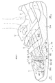
- the front end 20 of the second upper portion 2 tilts forward around the lower end 11 of the dividing line L1 along with the dorsiflexion. Displace as follows. That is, the front end 20 of the second upper portion 2 is displaced with respect to the first upper portion 1 so that the overlapping region ⁇ (non-bonded portion) increases. Therefore, even the first upper portion 1 and the second upper portion 2 having high bending rigidity are easily bent along the dorsiflexion of the foot.
- both the inner and outer upper portions 1 to 3 are easily bent, and as a result, the upper U along the foot is good.
- the front edge portion 21 of the second upper portion 2 is disposed below the first upper portion 1.
- the front edge portion 21 of the second upper portion 2 may be disposed above the first upper portion 1.
- the front end 20 of the second upper portion 2 appears as a dividing line L1, while the rear end of the first upper portion 1 becomes a hidden line.
- sample A the shoes of the embodiment shown in FIGS. 1 to 9
- sample B the shoes described in the other examples
- a pressure-sensitive sensor S shown in FIGS. 10A and 10B was prepared and arranged so as to cover the third and fourth MP joints MP3 and MP4 of the subject as shown in FIG. 10A.
- each virtual area (Xi, Yi) of the sensor S in FIG. 10B was measured.
- the measurement results are shown in FIG. 11A.
- the size and shape of each area (Xi, Yi) in FIG. 10B was a square with a side of 5 mm.
- the 2nd upper part 2 when the 2nd upper part 2 is arrange
- the upper edge 2 ⁇ / b> E faces the opening 6 in the second upper portion 2, and therefore has a flexible structure that can be deformed relatively freely as compared with the first upper portion 1. Therefore, when the front part of the second upper part 2 enters the lower side of the first upper part 1, the second upper part 2 follows the instep. For this reason, it is presumed that the pressure on the toes due to the deformation of the second upper portion 2 does not increase as a whole and does not increase locally.
- the first upper portion is deformed so that the height of the first upper portion having a rigid structure is slightly lowered at the time of dorsiflexion.
- the rear edge of the upper portion 1 (the portion corresponding to the reference symbol L1) rubs while pressing the surface of the toes.
- the footpad is subjected to the compression caused by the front portion of the second upper portion 2 pressing the upper surface of the first upper portion 1. .
- the first upper portion 1 is continuous with the third upper portion 3 in the foot width direction X, and the upper U of the toe portion is continuous in a dome shape (round roof shape). . That is, three sides of the toe portion are firmly supported by the soles Sm and So. Therefore, the first upper portion 1 has a rigid structure that cannot be freely deformed. The first upper portion 1 is also deformed when the second upper portion 2 is deformed, but the load with respect to the displacement amount of the first upper portion 1 of the rigid structure is generally larger than that of the second upper portion 2 of the flexible structure. It will increase significantly locally.
- the dividing line L1 in FIG. 1 extends to the upper end of the midsole Sm, and the outer continuous portion 12 may not be provided. Moreover, another parting line may be provided in the inner side M of FIG.
- the position in the front-rear direction Y of the dividing line L1 in FIG. 9 may be a position corresponding to the bone body of the minor phalange B35 or a position between the distal phalanx and the proximal phalanx of the fourth heel. Good.
- the number of the dividing lines L1 is not limited to one, and two or more may be provided.
- the 2nd parting line may be provided in joined part 1C where front part 1F and rear part 1B of the 1st upper part 1 of Drawing 1 were joined.
- these dividing lines L1 may be bent at a lower end portion in a gentle or steep curved shape toward the front or the rear.
- the preferred embodiments have been described with reference to the drawings. However, those skilled in the art will readily understand various changes and modifications within the obvious scope by looking at the present specification.
- the first and second upper portions do not need to be as rigid as the plate material of the above-described embodiment.
- the first and second upper portions have the same rigidity as the third upper portion or less than the rigidity of the third upper portion in artificial leather. May be.
- the structure of the present invention may be applied to both feet of shoes, or the structure of the present invention may be applied only to the axial foot. Accordingly, such changes and modifications are to be construed as within the scope of the present invention.
- the present invention is applicable not only to shoes for court competition such as handball and volleyball, but also to athletic shoes (athletic shoes) including indoor and outdoor competition shoes (shoes) and non-competitive shoes (shoes). It can also be applied to safety shoes.
Landscapes
- Chemical & Material Sciences (AREA)
- Engineering & Computer Science (AREA)
- Materials Engineering (AREA)
- Footwear And Its Accessory, Manufacturing Method And Apparatuses (AREA)
Abstract
Description
外側面において小趾球O5の側面を覆って支持する第2アッパー部2と、
静止立位および足が背屈した背屈状態において、前記第1アッパー部1と前記第2アッパー部2とが前記外側面において二重に重なり、かつ、互いに拘束しない重なり領域αと、
前記静止立位から足が背屈するのに伴い、前記第2アッパー部2の前端20が前記第1アッパー部1に対し変位することで、前記重なり領域αの面積が大きくなるように前記第1アッパー部1と第2アッパー部2とが互いに分断された分断ラインL1とを備え、
前記分断ラインL1の下端11の足の前後方向Yの位置は小趾の中足趾節関節MP5よりも前方YFで、かつ、第4趾の先端よりも後方YRに設定されている。
この場合、上記と同様に“棚落ち”が抑制される。また、第4趾の末節骨B14の先端よりも後方YRに分断ラインL1が設定されており、足沿いの更なる向上が期待できる。
この場合、後述するように、足沿いが更に向上するだろう。
前記シューレース4の一部は、前記複数の孔H1,H2のうち前記第1アッパー部1の孔と、前記複数の孔H1,H2のうち前記第2アッパー部2の孔との間において、前記第1アッパー部1の下側に配置されると共に、前記第2アッパー部2の上側に配置されている。
前記分断ラインL1の前記下端11から靴のソールSm,Soの上端S1まで前記第1アッパー部1と前記第2アッパー部2とが足の前後方向Yに前記重なり領域αよりも堅く互いに連なる外側連続部12を前記アッパーUが更に備える。
前記第1及び第2アッパー部1,2を構成する部材の曲げ剛性が前記第3アッパー部3を構成するそれよりも大きい。
前記第3アッパー部3は母趾の基節骨B31の骨底から母趾球O1まで前後に分断されることなく内側面を覆って連なる内側連続部32を有する。
前記分断ラインL1の下端11の足の前後方向Yの位置は小趾の基節骨B35の骨底よりも前方YFで、かつ、第4趾の先端よりも後方YRに設定されている。
前記第1及び第2アッパー部1,2を構成する部材の曲げ剛性が前記第3アッパー部3を構成するそれよりも大きく、
前記分断ラインL1の下端11の足の前後方向Yの位置は小趾の基節骨B35の骨底よりも前方YFで、かつ、第4趾の末節骨B14の先端よりも後方YRに設定されている。
前記第1及び第2アッパー部2を構成する部材の曲げ剛性が前記第3アッパー部3を構成するそれよりも大きく、
前記第3アッパー部3は母趾の基節骨B35の骨底から母趾球O1まで前後に分断されることなく内側面を覆って連なる内側連続部32を有する。
前記分断ラインL1は前記第1アッパー部1の上縁1Eから前記下端11まで下方に向かって、かつ、アッパーの履き口5の前方の開口6に連なり、前記開口6から足の外側に向かって延びており、
前記第1アッパー部1は前記開口6の前端ラインL2を定義し、
前記分断ラインL1と前記前端ラインL2とを連ねた連続ラインL3は、足の第2趾骨B2から第4趾骨B4を横断するように足幅方向Xに延びている。
以下、要部の説明に先立って、本実施例の全体構造が説明される。図1および図2に示す本実施例はたとえばハンドボールやバレーボール用の靴であり、ソールとアッパーUとを備える。
図1において、前記ソールは、互いに一体に結合されたアウトソールSo、ミッドソールSm、ヒールカウンタ7およびインソール(図示せず)を備える。なお、図7~図9においてミッドソールSmには不規則な小さな網点が付されている。図7の前記ミッドソールSmにはアッパーUが固着されている。
図1の前記ミッドソールSmは前記アウトソールSoの上に配置された熱可塑性樹脂の発泡体を主体とし、たとえば、EVAの発泡体を主体とし、一部にゲルなどの他の緩衝部材が含まれていてもよい。前記ミッドソールSmは前記外側Lにおいて、前記アウトソールSoの巻上部80とアッパーUとの間に挟まれ、図7の基節骨B35の骨底および小趾球O5の外側面を覆う巻上部81を有する。
前記外装材U2の材料としては、たとえば、人工皮革や合成皮革や熱可塑性樹脂の非発泡体の板材などの伸び難い又は実質的に伸びない材料を用いる。また、屈曲性を高めるために、外装材U2に貫通孔U0を設け、同貫通孔U0から内装材U1を構成するメッシュ材が露出していてもよい。
なお、前記開口6においては、メッシュ模様を施した前記内装材U1が露出する。
図1において、足の前足が外側Lに向かってアッパーU内で移動しようとすると、曲げ剛性の大きい第1アッパー部1および第2アッパー部2や前後に堅く連なった外側連続部12や巻上部80,81が図7の中足趾節関節MP5付近において前記移動を抑制する。そのため、“棚落ち”が生じにくくなるだろう。
図1~図9の前記実施例では第1アッパー部1の下側に第2アッパー部2の前縁部21が配置されている。しかし、逆に、第1アッパー部1の上側に第2アッパー部2の前縁部21が配置されてもよい。この場合、第2アッパー部2の前端20が分断ラインL1となって表れ、一方、第1アッパー部1の後端が隠れラインとなる。
今、図1の静止立位から図3の背屈姿勢への移行時において、第2アッパー部2の前部、つまり、図7の小趾の基節骨B35の前端である趾節間関節Jの付近における第2アッパー部2の変形に着目する。図1および図3からわかるように、前記第2アッパー部2の前部は足の背屈に伴って背屈する。
たとえば、シューレースが案内手段Gを構成する必要はない。
また、第1および第2アッパー部は前記実施例の板材のように剛性の大きい必要はなく、たとえば、人工皮革で第3アッパー部と同じ剛性や第3アッパー部の剛性よりも小さい剛性であってもよい。
また、シューズは両足に本発明の構造が適用されてもよいし、軸足のみに本発明の構造が適用されてもよい。
したがって、そのような変更および修正は本発明の範囲のものと解釈される。
1B:後部 1C:接合部 1E:上縁 1F:前部
2:第2アッパー部 2E:上縁 20:前端 21:前縁部
3:第3アッパー部 32:内側連続部
4:シューレース 5:履き口 6:開口
7:ヒールカウンタ
80,81:巻上部
B2:趾骨 B4:趾骨 B14:末節骨 B35:基節骨 B45:中足骨
G:案内手段 H1,H2:孔
L:外側 M:内側
L1:分断ライン L11:隠れライン L2:前端ライン L3:連続ライン
LF:後端面
MP5:中足趾節関節 O1:母趾球 O5:小趾球
α:重なり領域 αC:結合部
S:センサ Sm,So:ソール S1:上端
U:アッパー U0:貫通孔 U1:内装材 U2:外装材
X:足幅方向
Y:前後方向 YF:前方 YR:後方
Claims (15)
- 靴のアッパーUであって、
爪先の外側Lを覆う第1アッパー部1と、
外側面において小趾球O5の側面を覆って支持する第2アッパー部2と、
静止立位および足が背屈した背屈状態において、前記第1アッパー部1と前記第2アッパー部2とが前記外側面において二重に重なり、かつ、互いに拘束しない重なり領域αと、
前記静止立位から足が背屈するのに伴い、前記第2アッパー部2の前端20が前記第1アッパー部1に対し変位することで、前記重なり領域αの面積が大きくなるように前記第1アッパー部1と第2アッパー部2とが互いに分断された分断ラインL1とを備え、
前記分断ラインL1の下端11の足の前後方向Yの位置は小趾の中足趾節関節MP5よりも前方YFで、かつ、第4趾の先端よりも後方YRに設定されている。 - 請求項1のアッパーにおいて、前記分断ラインL1の下端11の足の前後方向Yの位置は小趾の基節骨B35の骨底よりも前方YFで、かつ、第4趾の先端よりも後方YRに設定されている。
- 請求項1のアッパーにおいて、前記分断ラインL1の下端11の足の前後方向Yの位置は小趾の基節骨B35の骨底よりも前方YFで、かつ、第4趾の末節骨B14の先端よりも後方YRに設定されている。
- 請求項1~3のいずれか1項のアッパーにおいて、前記重なり領域αは、前記静止立位において、前記第2アッパー部2の前縁部21が前記第1アッパー部1の下側に潜り込んだ状態に設定されている。
- 請求項1~3のいずれか1項のアッパーにおいて、前記第1アッパー部1の下側に前記第2アッパー部2が潜り込んだ状態で、前記重なり領域αにおいて前記両アッパー部が互いに重なるように、前記両アッパー部の重なり状態を案内する案内手段Gを更に備える。
- 請求項5のアッパーにおいて、前記案内手段Gは、前記静止立位において、前記第2アッパー部2の前縁部21が前記第1アッパー部1の下側に潜り込んだ状態の前記重なり領域αを包含する。
- 請求項5もしくは6のアッパーにおいて、前記案内手段Gは、前記アッパーUの紐通し用の複数の孔H1,H2に挿通されるシューレース4を更に備え、
前記シューレース4の一部は、前記複数の孔H1,H2のうち前記第1アッパー部1の孔と、前記複数の孔H1,H2のうち前記第2アッパー部2の孔との間において、前記第1アッパー部1の下側に配置されると共に、前記第2アッパー部2の上側に配置されている。 - 請求項1~7のいずれか1項のアッパーにおいて、前記分断ラインL1は前記第1アッパー部1の上縁1Eから前記下端11まで下方に向かって、かつ、アッパーUの履き口5の前方の開口6に連なり前記開口6から足の外側に向かって前記下端11まで延びており、
前記分断ラインL1の前記下端11から靴のソールSm,Soの上端S1まで前記第1アッパー部1と前記第2アッパー部2とが足の前後方向Yに前記重なり領域αよりも堅く互いに連なる外側連続部12を前記アッパーUが更に備える。 - 請求項8のアッパーにおいて、前記外側連続部12は、前記第1アッパー部1と前記第2アッパー部2とが互いに結合されて形成されている。
- 請求項1~9のいずれか1項のアッパーにおいて、内側面において母趾球O1の側面を覆って支持する第3アッパー部3を更に備え、
前記第1及び第2アッパー部1,2を構成する部材の曲げ剛性が前記第3アッパー部3を構成するそれよりも大きい。 - 請求項1~10のいずれか1項のアッパーにおいて、内側面において母趾球O1の側面を覆って支持する第3アッパー部3を更に備え、
前記第3アッパー部3は母趾の基節骨B31の骨底から母趾球O1まで前後に分断されることなく内側面を覆って連なる内側連続部32を有する。 - 請求項1のアッパーにおいて、前記第1アッパー部1の下側に前記第2アッパー部2が潜り込んだ状態で、前記重なり領域αにおいて両アッパー部が互いに重なるように、前記両アッパーの重なり状態を案内する案内手段Gを更に備え、
前記分断ラインL1の下端11の足の前後方向Yの位置は小趾の基節骨B35の骨底よりも前方YFで、かつ、第4趾の先端よりも後方YRに設定されている。 - 請求項1のアッパーにおいて、内側面において母趾球O1の側面を覆って支持する第3アッパー部3を更に備え、
前記第1及び第2アッパー部1,2を構成する部材の曲げ剛性が前記第3アッパー部3を構成するそれよりも大きく、
前記分断ラインL1の下端11の足の前後方向Yの位置は小趾の基節骨B35の骨底よりも前方YFで、かつ、第4趾の末節骨B14の先端よりも後方YRに設定されている。 - 請求項1のアッパーにおいて、内側面において母趾球O1の側面を覆って支持する第3アッパー部3を更に備え、
前記第1及び第2アッパー部2を構成する部材の曲げ剛性が前記第3アッパー部3を構成するそれよりも大きく、
前記第3アッパー部3は母趾の基節骨B35の骨底から母趾球O1まで前後に分断されることなく内側面を覆って連なる内側連続部32を有する。 - 請求項1~14のいずれか1項のアッパーにおいて、
内側面において爪先及び母趾球の側面を覆って支持する第3アッパー部3を備え、
前記分断ラインL1は前記第1アッパー部1の上縁1Eから前記下端11まで下方に向かって、かつ、アッパーの履き口5の前方の開口6に連なり、前記開口6から足の外側に向かって延びており、
前記第1アッパー部1は前記開口6の前端ラインL2を定義し、
前記分断ラインL1と前記前端ラインL2とを連ねた連続ラインL3は、足の第2趾骨B2から第4趾骨B4を横断するように足幅方向Xに延びている。
Priority Applications (3)
| Application Number | Priority Date | Filing Date | Title |
|---|---|---|---|
| PCT/JP2014/057522 WO2015140957A1 (ja) | 2014-03-19 | 2014-03-19 | 靴のアッパー |
| JP2016508393A JP6310545B2 (ja) | 2014-03-19 | 2014-03-19 | 靴のアッパー |
| EP14886036.4A EP3120721B1 (en) | 2014-03-19 | 2014-03-19 | Shoe upper |
Applications Claiming Priority (1)
| Application Number | Priority Date | Filing Date | Title |
|---|---|---|---|
| PCT/JP2014/057522 WO2015140957A1 (ja) | 2014-03-19 | 2014-03-19 | 靴のアッパー |
Publications (1)
| Publication Number | Publication Date |
|---|---|
| WO2015140957A1 true WO2015140957A1 (ja) | 2015-09-24 |
Family
ID=54143964
Family Applications (1)
| Application Number | Title | Priority Date | Filing Date |
|---|---|---|---|
| PCT/JP2014/057522 WO2015140957A1 (ja) | 2014-03-19 | 2014-03-19 | 靴のアッパー |
Country Status (3)
| Country | Link |
|---|---|
| EP (1) | EP3120721B1 (ja) |
| JP (1) | JP6310545B2 (ja) |
| WO (1) | WO2015140957A1 (ja) |
Cited By (1)
| Publication number | Priority date | Publication date | Assignee | Title |
|---|---|---|---|---|
| CN114449915A (zh) * | 2019-09-27 | 2022-05-06 | 株式会社爱世克私 | 鞋 |
Families Citing this family (2)
| Publication number | Priority date | Publication date | Assignee | Title |
|---|---|---|---|---|
| CN106993849B (zh) * | 2017-04-10 | 2022-06-10 | 北京小米移动软件有限公司 | 鞋类物品 |
| CN107549929B (zh) * | 2017-10-17 | 2020-10-27 | 北京小米移动软件有限公司 | 鞋类物品 |
Citations (2)
| Publication number | Priority date | Publication date | Assignee | Title |
|---|---|---|---|---|
| WO2008047659A1 (fr) * | 2006-10-19 | 2008-04-24 | Asics Corporation | Chaussure de sport présentant un ajustement amélioré de la partie de tige |
| JP2009254807A (ja) * | 2008-03-27 | 2009-11-05 | Mizuno Corp | シューズのアッパー構造 |
Family Cites Families (3)
| Publication number | Priority date | Publication date | Assignee | Title |
|---|---|---|---|---|
| US4677769A (en) * | 1986-02-28 | 1987-07-07 | Eddress Ahmad | Footwear with pivotal toe |
| DE112004000536B4 (de) * | 2003-04-24 | 2017-08-24 | Asics Corp. | Sportschuh mit einem Schaft, dessen Anpassungsvermögen verbessert ist |
| JP2011087893A (ja) * | 2009-10-22 | 2011-05-06 | Shigeru Nakanishi | 通気性靴 |
-
2014
- 2014-03-19 WO PCT/JP2014/057522 patent/WO2015140957A1/ja active Application Filing
- 2014-03-19 JP JP2016508393A patent/JP6310545B2/ja active Active
- 2014-03-19 EP EP14886036.4A patent/EP3120721B1/en active Active
Patent Citations (2)
| Publication number | Priority date | Publication date | Assignee | Title |
|---|---|---|---|---|
| WO2008047659A1 (fr) * | 2006-10-19 | 2008-04-24 | Asics Corporation | Chaussure de sport présentant un ajustement amélioré de la partie de tige |
| JP2009254807A (ja) * | 2008-03-27 | 2009-11-05 | Mizuno Corp | シューズのアッパー構造 |
Cited By (1)
| Publication number | Priority date | Publication date | Assignee | Title |
|---|---|---|---|---|
| CN114449915A (zh) * | 2019-09-27 | 2022-05-06 | 株式会社爱世克私 | 鞋 |
Also Published As
| Publication number | Publication date |
|---|---|
| EP3120721A4 (en) | 2017-12-27 |
| JP6310545B2 (ja) | 2018-04-11 |
| EP3120721A1 (en) | 2017-01-25 |
| EP3120721B1 (en) | 2018-10-03 |
| JPWO2015140957A1 (ja) | 2017-04-06 |
Similar Documents
| Publication | Publication Date | Title |
|---|---|---|
| EP3897266B1 (en) | Footwear article with asymmetric ankle collar | |
| US11633016B2 (en) | Footwear article with tongue reinforcer | |
| TWI680728B (zh) | 具有可調適配合度的鞋類物品(一) | |
| US20210177070A1 (en) | Method including footwear and sock having aligning indicia | |
| JP4219591B2 (ja) | フットウエアの緊締構造 | |
| JP5909032B1 (ja) | 靴のアッパー | |
| US20230012918A1 (en) | Footwear article capable of hands-free donning | |
| US10834990B2 (en) | Foot support members that provide dynamically transformative properties | |
| EP2559352B1 (en) | Structure for forefoot section of shoe upper part | |
| US8595957B2 (en) | Unitary upper and midsole | |
| US10750825B2 (en) | Shoes | |
| US20170265561A1 (en) | Standoff Unit For A Control Device In An Article Of Footwear | |
| JP6310545B2 (ja) | 靴のアッパー | |
| US11439201B2 (en) | Pair of asymmetrical footwear articles |
Legal Events
| Date | Code | Title | Description |
|---|---|---|---|
| 121 | Ep: the epo has been informed by wipo that ep was designated in this application |
Ref document number: 14886036 Country of ref document: EP Kind code of ref document: A1 |
|
| ENP | Entry into the national phase |
Ref document number: 2016508393 Country of ref document: JP Kind code of ref document: A |
|
| NENP | Non-entry into the national phase |
Ref country code: DE |
|
| REEP | Request for entry into the european phase |
Ref document number: 2014886036 Country of ref document: EP |
|
| WWE | Wipo information: entry into national phase |
Ref document number: 2014886036 Country of ref document: EP |