WO2015137154A1 - 真空精錬炉用ガス供給装置 - Google Patents
真空精錬炉用ガス供給装置 Download PDFInfo
- Publication number
- WO2015137154A1 WO2015137154A1 PCT/JP2015/055807 JP2015055807W WO2015137154A1 WO 2015137154 A1 WO2015137154 A1 WO 2015137154A1 JP 2015055807 W JP2015055807 W JP 2015055807W WO 2015137154 A1 WO2015137154 A1 WO 2015137154A1
- Authority
- WO
- WIPO (PCT)
- Prior art keywords
- gas supply
- gas
- pipe
- ladle
- pressure
- Prior art date
- Legal status (The legal status is an assumption and is not a legal conclusion. Google has not performed a legal analysis and makes no representation as to the accuracy of the status listed.)
- Ceased
Links
Images
Classifications
-
- C—CHEMISTRY; METALLURGY
- C21—METALLURGY OF IRON
- C21C—PROCESSING OF PIG-IRON, e.g. REFINING, MANUFACTURE OF WROUGHT-IRON OR STEEL; TREATMENT IN MOLTEN STATE OF FERROUS ALLOYS
- C21C7/00—Treating molten ferrous alloys, e.g. steel, not covered by groups C21C1/00 - C21C5/00
- C21C7/04—Removing impurities by adding a treating agent
- C21C7/072—Treatment with gases
-
- C—CHEMISTRY; METALLURGY
- C21—METALLURGY OF IRON
- C21C—PROCESSING OF PIG-IRON, e.g. REFINING, MANUFACTURE OF WROUGHT-IRON OR STEEL; TREATMENT IN MOLTEN STATE OF FERROUS ALLOYS
- C21C7/00—Treating molten ferrous alloys, e.g. steel, not covered by groups C21C1/00 - C21C5/00
-
- B—PERFORMING OPERATIONS; TRANSPORTING
- B22—CASTING; POWDER METALLURGY
- B22D—CASTING OF METALS; CASTING OF OTHER SUBSTANCES BY THE SAME PROCESSES OR DEVICES
- B22D1/00—Treatment of fused masses in the ladle or the supply runners before casting
-
- C—CHEMISTRY; METALLURGY
- C21—METALLURGY OF IRON
- C21C—PROCESSING OF PIG-IRON, e.g. REFINING, MANUFACTURE OF WROUGHT-IRON OR STEEL; TREATMENT IN MOLTEN STATE OF FERROUS ALLOYS
- C21C7/00—Treating molten ferrous alloys, e.g. steel, not covered by groups C21C1/00 - C21C5/00
- C21C7/10—Handling in a vacuum
Definitions
- the present invention relates to a gas supply device for supplying gas to molten metal in a vacuum refining furnace.
- refining is performed to remove carbon and impurities that deteriorate the properties of the metal from the molten metal produced by melting the raw materials.
- the refining process is composed of a primary refining process and a secondary refining process.
- decarburization is performed by blowing oxygen to the molten metal in the converter to remove the carbon contained in the molten metal, and the impurities are oxidized and taken into the slag for melting. Remove from metal.
- the molten metal after primary refining transferred from the converter to the ladle is placed in the vacuum tank of the vacuum refining furnace together with the ladle, and oxygen is blown into the molten metal while reducing the pressure in the vacuum tank.
- decarburization treatment is performed, and carbon and impurities remaining in the molten metal are oxidized and further removed.
- the molten metal is stirred by blowing an inert gas such as argon gas into the molten metal from the bottom of the ladle in order to promote the reaction between oxygen and the content of the molten metal. Is done.
- Patent Document 1 describes a gas supply device that supplies gas to molten metal in a ladle by supplying gas from a gas supply source to a gas blowing plug attached to the bottom of the ladle.
- this gas supply apparatus contains the tank which stores gas, the valve which controls the flow of gas, piping, a coupling, etc.
- the gas supply device described in Patent Document 1 is attached to a ladle and configured to move with the ladle. Moreover, a vacuum chamber may be arrange
- the present invention has been made to solve such problems, and aims to provide a gas supply device for a vacuum refining furnace which is attached to a ladle in a vacuum refining furnace and has improved heat resistance. To do.
- a gas supply apparatus for a vacuum smelting furnace supplies an inert gas from an external gas supply source to molten metal in a ladle disposed in a vacuum tank of a vacuum smelting furnace.
- a vacuum refining furnace gas supply device attached to the ladle is provided with a pipe and a valve for connecting an inert gas supply plug inserted into the ladle wall and an external gas supply source.
- the heat-resistant temperature of elements involved in sealing and the heat-resistant temperature of elements involved in valve operation are 400 ° C. or higher.
- the gas supply device for a vacuum smelting furnace it is possible to improve heat resistance so that durability can be ensured while being attached to a ladle in the vacuum smelting furnace.
- VOD vacuum refining furnace
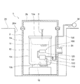
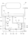
- gas supply device for vacuum refining furnace concerning an embodiment of the invention. It is a side view which shows the detail of the gas supply apparatus for vacuum smelting furnaces of FIG.
- FIG. 1 a vacuum refining furnace gas supply device 100 and a vacuum refining furnace 1 including a vacuum refining furnace gas supply device 100 according to an embodiment of the present invention are shown.
- the vacuum refining furnace 1 is a vacuum oxygen decarburizer (VOD) used in a secondary refining process in the production of stainless steel.
- VOD vacuum oxygen decarburizer
- the VOD 1 has a vacuum chamber 2 in which the ladle 10 can be placed and an airtight sealed space can be formed.
- the vacuum chamber 2 is configured in two parts.
- the vacuum chamber 2 has a bottomed cylindrical main body 2a disposed on the lower side and a lid 2b that can airtightly close the opening of the main body 2a from the upper side.
- the vacuum chamber 2 is disposed in an underground pit 20a dug down from the ground surface 20 downward. At this time, the main body portion 2a is located in the underground pit 20a, and the boundary surface between the main body portion 2a and the lid portion 2b is substantially the same level as the ground surface 20.
- an exhaust pipe 2c for discharging the air inside the vacuum chamber 2 to the outside of the vacuum chamber 2 extends from the side portion of the main body 2a.
- the exhaust pipe 2c is configured to be connected to a vacuum pump and a steam ejector (not shown). By operating the vacuum pump and the vapor ejector, the inside of the vacuum chamber 2 is depressurized.
- a ladle 10 in the vacuum chamber 2 contains a molten stainless steel 11 that is a molten metal after carbon and impurities are removed by a converter in a primary refining process.
- the VOD 1 has an oxygen lance 3 that extends from the outside of the vacuum chamber 2 to the inside of the vacuum chamber 2 through the lid 2 b.
- the oxygen lance 3 extends through the inner lid 10 a at the top of the ladle 10 installed in the vacuum chamber 2, and is configured to blow oxygen onto the surface of the molten stainless steel 11 in the ladle 10. ing.
- a porous plug 12 for sending argon gas, which is an inert gas for stirring, to the molten stainless steel 11 is inserted into the bottom wall portion 10 b of the ladle 10.
- a supply portion such as argon gas is formed of a porous material.
- the porous plug 12 is connected to a pipe 132 of a vacuum refining furnace gas supply device 100 for controlling supply of argon gas or the like to the molten stainless steel 11.
- the vacuum refining furnace gas supply device 100 is attached to the outer surface of the cylindrical side wall portion 10 c of the ladle 10 in the vacuum chamber 2.
- the vacuum refining furnace gas supply device 100 includes a control unit 110, an accumulator tank 120, and piping.
- the pressure accumulating tank 120 and the control unit 110 are arranged in the order of the pressure accumulating tank 120 and the control unit 110 from the intermediate height position of the side wall portion 10 c to the lower side with respect to the side wall portion 10 c of the ladle 10.
- Gas supply pipes 131 and 132 extend from the control unit 110.
- the gas supply pipe 131 is connected to the external gas supply pipe 130 inside the vacuum chamber 2.
- the external gas supply pipe 130 extends from the inside of the vacuum chamber 2 to the outside of the vacuum chamber 2 through the side portion of the main body 2a, and further supplies argon gas or the like disposed on the ground surface 20
- An external gas supply source 30 is connected.
- the gas supply pipe 132 is connected to the porous plug 12 as described above.
- the internal gas supply pipe 131 has two branch pipe portions 131a and 131b located in the control unit 110 in the middle thereof.
- the branch pipe part 131a is located upstream of the branch pipe part 131b, which is the gas supply source 30 side.
- a gas direct supply pipe 132 connected to the porous plug 12 (see FIG. 1) of the ladle 10 after being extended to the outside of the control unit 110 through the control unit 110 is connected to the branch pipe portion 131a.
- the gas direct supply pipe 132 has a branch pipe portion 132 a located in the control unit 110 in the middle of the gas direct supply pipe 132.
- the joint portion 141 that hermetically connects the branch pipe portion 131a and the gas direct supply pipe 132 is configured by a bite-type joint that is a double ferrule-type joint such as Swagelok (registered trademark).
- the bite type joint is configured so that elements such as a front ferrule and a back ferrule that constitute the joint part 141 are thermally expanded, thereby tightening the pipe to the joint body covering the outside, and connecting the connected pipes to each other. Acts to increase airtightness. For this reason, the bite type joint has a structure that tightens without loosening at high temperatures.
- the joint part 141 may be a screw-in type joint, and in this case, in order to improve airtightness, it is accompanied by sealing by welding.
- a tank gas supply pipe 133 connected to the branch pipe section 132a through the control unit 110 is connected to the branch pipe section 131b.
- the tank gas supply pipe 133 is composed of five pipe sections 133a, 133b, 133c, 133d and 133e connected in series.
- One end of the first pipe section 133a is connected to the branch pipe part 131b, and one end of the fifth pipe section 133e is connected to the branch pipe part 132a. From the branch pipe part 131b to the branch pipe part 132a, the first pipe section 133a to the fifth pipe section 133e are arranged in the above order and connected to each other at their ends.
- the joint part 147 between 133e and the branch pipe part 132a has the same configuration as the joint part 141.
- a second check valve 152 is provided between the branch pipe part 131 a and the branch pipe part 131 b in the internal gas supply pipe 131.
- the second check valve 152 allows a gas flow in a direction from the branch pipe portion 131a to the branch pipe portion 131b, that is, a gas flow in a direction from the gas supply source 30 to the pressure accumulation tank 120, and a gas in the opposite direction.
- a first check valve 151 is provided between the joint part 141 and the branch pipe part 132 a in the gas direct supply pipe 132.
- the first check valve 151 allows the gas flow in the direction from the branch pipe portion 131a toward the ladle 10 and blocks the gas flow in the opposite direction. Therefore, the first check valve 151 allows the gas flow in the direction from the gas supply source 30 to the ladle 10 in the gas direct supply pipe 132 and blocks the gas flow in the opposite direction.
- a third check valve 153 is provided in the middle of the fifth pipe section 133e in the tank gas supply pipe 133.
- the third check valve 153 allows the gas flow in the direction from the fourth pipe section 133d toward the branch pipe portion 132a, and blocks the gas flow in the opposite direction. Therefore, the third check valve 153 allows the gas flow in the direction from the pressure accumulation tank 120 toward the ladle 10 in the tank gas supply pipe 133 and prevents the gas flow in the opposite direction.
- the first pipe section 133a of the tank gas supply pipe 133 has a branch pipe part 133a1 in the middle thereof.
- a relief valve 156 is connected to the distal end of the branch pipe part 133a1.
- the relief valve 156 operates so as to be opened when a pressure equal to or higher than a predetermined upper limit pressure is generated in the first pipe section 133a and to release the gas inside the pipe to the outside. This prevents an excessive increase in pressure in the first pipe section 133a, that is, in the pipe from the pressure accumulation tank 120 through the tank gas supply pipe 133 to the ladle 10.
- a pressure adjustment valve 155 and a needle valve 154 are provided in the middle of the third pipe section 133c of the tank gas supply pipe 133.
- the pressure adjustment valve 155 and the needle valve 154 are arranged in the order of the pressure adjustment valve 155 and the needle valve 154 along the direction from the second pipe section 133b to the fourth pipe section 133d.
- the pressure adjustment valve 155 adjusts the pressure of the gas flowing through the tank gas supply pipe 133.
- the set pressure of the pressure adjustment valve 155 is set lower than the pressure of the gas flowing through the internal gas supply pipe 131 when the gas is supplied from the gas supply source 30.
- the pressure regulating valve 155 is configured to open when the pressure on the downstream side of the fifth pipe section 133e is equal to or lower than the set pressure, and to close when the pressure on the fifth pipe section 133e side becomes higher than the set pressure. ing. Therefore, the pressure regulating valve 155 controls the pressure of the gas flowing through the pressure regulating valve 155 to be equal to or lower than the set pressure. As a result, when the gas from the gas supply source 30 flows through the internal gas supply pipe 131 through the external gas supply pipe 130 (see FIG. 1) to the pressure accumulation tank 120 and to the gas direct supply pipe 132, the pressure is increased.
- the needle valve 154 is configured to adjust the flow rate of the gas flowing in the third pipe section 133c, that is, the tank gas supply pipe 133, by adjusting the opening degree thereof.
- the temperature around the side wall 10c (see FIG. 1) of the ladle 10 in the vacuum chamber 2 (see FIG. 1) disposed in the underground pit 20a is less than 400 ° C.
- the component whose heat-resistant temperature is 400 degreeC or more was selected as shown in Table 1 above.
- the packing has a predetermined sealing ability in an environment of a heat resistant temperature or lower.
- the spring has elasticity with a predetermined spring elastic modulus in an environment of a heat resistant temperature or lower.
- the ferrule and the joint body are thermally expanded in an environment below the heat-resistant temperature, but maintain a predetermined strength and do not deform so as to impair the function.
- the components and valve operations related to sealing in each valve and each joint portion can suppress deterioration of performance due to heat.
- the vacuum refining furnace gas supply device 100 operates as follows when the VOD 1 is operated. 1 and 2 together, after the internal gas supply pipe 131 is connected to the gas supply source 30 via the external gas supply pipe 130 of the vacuum refining furnace gas supply apparatus 100, the operation of the VOD 1 is started. Then, an inert gas such as argon gas is supplied from the gas supply source 30 to the internal gas supply pipe 131. At the same time, in the vacuum chamber 2, oxygen gas is blown from the oxygen lance 3 onto the surface of the molten stainless steel 11 in the ladle 10. Further, a vacuum pump and a steam ejector (not shown) connected to the exhaust pipe 2c are operated, and the vacuum in the vacuum chamber 2 is also reduced. By this depressurization action, the reaction between the blown oxygen gas and the carbon in the molten stainless steel 11, that is, the decarburization process is promoted.
- an inert gas such as argon gas
- an inert gas is supplied into the molten stainless steel 11 through the porous plug 12, and the molten stainless steel 11 is stirred. Thereby, reaction with the content in the stainless steel molten steel 11 and the oxygen gas blown is promoted. Therefore, when the operation of VOD 1 is started, the inert gas is supplied to the ladle 10 and stored in the pressure accumulation tank 120.
- the relief valve 156 opens to release the inert gas to the outside. To prevent excessive pressure buildup.
- the porous plug 12 Since the porous plug 12 has a porous portion, there is a possibility that the molten stainless steel 11 flows down and penetrates into the porous portion. However, when the inert gas supplied from the pressure accumulation tank 120 fills the porous plug 12 in a pressurized state, the penetration of the molten stainless steel 11 is prevented. Thereby, the penetration of the molten stainless steel 11 into the porous plug 12 is prevented until the molten stainless steel 11 in the ladle 10 is used in the casting process subsequent to the secondary refining process.
- the supply of the inert gas to the porous plug 12 is controlled by adjusting the pressure by the pressure adjusting valve 155 and adjusting the flow rate by the needle valve 154. When the molten stainless steel 11 penetrates into the porous portion of the porous plug 12, when the inert gas is supplied again to the molten stainless steel 11 in the pan 10, the penetrated portion may peel off and the porous plug 12 may be damaged. .
- the vacuum refining furnace gas supply device 100 applies an inert gas such as argon gas from the gas supply source 30 to the molten stainless steel 11 in the ladle 10 disposed in the vacuum tank 2 of the VOD 1. It is attached to the ladle 10 while being supplied.
- the gas supply device 100 for a vacuum refining furnace includes a pipe and a valve that connect an inert gas supply porous plug 12 inserted into the bottom wall portion 10 b of the ladle 10 and a gas supply source 30.
- the heat resistance temperature of the ferrule, joint body, packing, spring, etc. of the joint part which is an element related to the sealing of the piping and valve and an element related to the operation of the valve, is 400 ° C. or higher.
- the element for maintaining the airtightness in the gas supply apparatus 100 for a vacuum refining furnace attached to the ladle 10 and the element related to the operation of the valve are the high temperature states in the secondary refining at VOD1. It has a heat-resistant temperature that is higher than the ambient temperature. For this reason, even if the gas supply apparatus 100 for vacuum smelting furnaces is attached to the ladle 10, it is possible to suppress degradation in performance and durability due to the heat of the ladle 10.
- the joint portions 141 to 147 of the pipes act so as to enhance the airtightness between the pipes when the elements constituting the joint parts 141 to 147 are thermally expanded.
- the airtightness of the joints 141 to 147 is improved, so a vacuum refining furnace that handles inert gas such as pressurized argon gas.
- the working gas supply apparatus 100 can sufficiently exhibit its performance.
- the vacuum refining furnace gas supply apparatus 100 includes a pressure accumulation tank 120 capable of storing an inert gas such as argon gas, and a first pipe line (that is, an inert gas supplied from the gas supply source 30 to the porous plug 12 (that is, The external gas supply pipe 130, the internal gas supply pipe 131, and the gas direct supply pipe 132, and the second pipe for sending the inert gas from the gas supply source 30 to the pressure accumulation tank 120 (that is, An external gas supply pipe 130 and an internal gas supply pipe 131), and a third pipe (that is, the internal gas supply pipe 131) for sending the inert gas in the pressure accumulation tank 120 to the porous plug 12.
- a first pipe line that is, an inert gas supplied from the gas supply source 30 to the porous plug 12
- a first pipe line that is, an inert gas supplied from the gas supply source 30 to the porous plug 12
- a first pipe line that is, an inert gas supplied from the gas supply source 30 to the porous plug 12
- a second check valve 152 provided in the second pipe and blocking the flow of gas from the pressure accumulation tank 120 toward the gas supply source 30, and a pressure accumulation tank 120 provided in the third pipe and from the porous plug 12.
- a third check valve 153 that prevents the flow of gas toward the gas, and the pressure of the gas that flows through the third pipe can be made lower than the pressure of the gas that is provided in the third pipe and flows through the first pipe.
- a pressure regulating valve 155 a pressure regulating valve 155.
- the inert gas when the inert gas is directly supplied from the gas supply source 30 to the porous plug 12, the inert gas can also be supplied to the pressure accumulation tank 120.
- the pressure regulating valve 155 provided in the third pipeline is set so that the pressure of the gas flowing through the third pipeline is lower than the pressure of the gas flowing through the first pipeline. That is, the set pressure, which is the upper limit pressure at which the pressure regulating valve 155 opens the third pipeline, is lower than the pressure of the gas flowing through the first pipeline.
- the 155 prevents the gas in the pressure accumulation tank 120 from flowing through the third pipe line, and as a result, the pressure in the pressure accumulation tank 120 is maintained.
- the inert gas is supplied from the pressure accumulation tank 120 to the porous plug 12, and the molten stainless steel that contacts the porous plug 12 by the pressure of the supplied inert gas. 11 is prevented from penetrating into the porous plug 12.
- the vacuum refining furnace gas supply device 100 is configured to be attached to a ladle 10 for stainless steel making, it is not limited thereto.
- the vacuum refining furnace gas supply device 100 may be provided for a ladle that needs to supply gas to the internal molten metal when a metal other than stainless steel is manufactured.
Landscapes
- Chemical & Material Sciences (AREA)
- Engineering & Computer Science (AREA)
- Materials Engineering (AREA)
- Metallurgy (AREA)
- Organic Chemistry (AREA)
- Mechanical Engineering (AREA)
- Treatment Of Steel In Its Molten State (AREA)
- Waste-Gas Treatment And Other Accessory Devices For Furnaces (AREA)
Abstract
VOD1の真空槽2内に配置された取鍋10内のステンレス溶鋼11にガス供給源30のアルゴンガス等の不活性ガスを供給すると共に取鍋10に取り付けられる真空精錬炉用ガス供給装置100は、取鍋10の底壁部10bに挿入される不活性ガス供給用のポーラスプラグ12とガス供給源30とを接続する配管及び弁を備える。配管及び弁における封止に関わる要素の耐熱温度と弁の作動に関わる要素の耐熱温度とが、400℃以上である。
Description
本発明は、真空精錬炉内の溶融金属にガスを供給するためのガス供給装置に関する。
金属の製造工程では、原料を溶解させて生成した溶融金属から、金属の特性を低下させる炭素及び不純物を除去する精錬が行われる。精錬工程は、一次精錬工程と二次精錬工程とから構成されている。一次精錬工程では、転炉内の溶融金属に対して酸素を吹精することによって脱炭処理を行い、溶融金属に含有される炭素を除去すると共に、不純物を酸化させてスラグに取り込ませ、溶融金属から除去する。二次精錬工程では、転炉から取鍋に移した一次精錬後の溶融金属を取鍋と共に真空精錬炉の真空槽の中に入れ、真空槽内を減圧しつつ溶融金属に酸素を吹精することによって脱炭処理を行い、溶融金属に残存している炭素及び不純物を酸化させてさらに除去する。二次精錬工程の脱炭処理では、酸素と溶融金属の含有物との反応を促進するために、取鍋の底部からアルゴンガス等の不活性ガスを溶融金属に吹き込むことによって、溶融金属の攪拌が行われる。例えば、特許文献1には、取鍋の底部に取り付けられたガス吹き込みプラグにガス供給源からのガスを供給することによって取鍋内の溶融金属にガスを供給するガス供給装置が記載されている。そして、このガス供給装置は、ガスを貯留するタンク、ガスの流れを制御する弁、配管、継手等を含んでいる。
特許文献1に記載されるガス供給装置は、取鍋に取り付けられて取鍋と共に移動するように構成されている。また、真空槽は、地上面よりも下げられた地下ピット内に配置されることがある。この場合、地下ピット内に熱が滞留し、真空槽と真空槽の内部の取鍋とが高温になるため、ガス供給装置の弁、継手等における気密性を保つための封止要素の耐久性が低下するという問題がある。
本発明はこのような問題点を解決するためになされたものであり、真空精錬炉内の取鍋に取り付けられ、耐熱性を向上させた真空精錬炉用ガス供給装置を提供することを目的とする。
上記の課題を解決するために、本発明に係る真空精錬炉用ガス供給装置は、真空精錬炉の真空槽内に配置された取鍋内の溶融金属に外部ガス供給源の不活性ガスを供給すると共に取鍋に取り付けられる真空精錬炉用ガス供給装置において、取鍋の壁部に挿入される不活性ガス供給用のプラグと外部ガス供給源とを接続する配管及び弁を備え、配管及び弁における封止に関わる要素の耐熱温度と弁の作動に関わる要素の耐熱温度とが400℃以上である。
本発明に係る真空精錬炉用ガス供給装置によれば、真空精錬炉内の取鍋に取り付けられながらも耐久性を確保できるように、耐熱性を向上させることが可能になる。
以下、本発明の実施の形態について添付図面に基づいて説明する。
図1を参照すると、本発明の実施の形態に係る真空精錬炉用ガス供給装置100と、真空精錬炉用ガス供給装置100を含む真空精錬炉1とが、示されている。
なお、以下の実施の形態では、真空精錬炉1は、ステンレス鋼の製鋼における二次精錬工程で使用される真空酸素脱炭装置(VOD)とする。
図1を参照すると、本発明の実施の形態に係る真空精錬炉用ガス供給装置100と、真空精錬炉用ガス供給装置100を含む真空精錬炉1とが、示されている。
なお、以下の実施の形態では、真空精錬炉1は、ステンレス鋼の製鋼における二次精錬工程で使用される真空酸素脱炭装置(VOD)とする。
VOD1は、内部に取鍋10を入れることができ且つ内部に気密な密閉空間を形成することができる真空槽2を有している。真空槽2は、二分割式に構成されている。真空槽2は、下側に配置される有底筒状をした本体部2aと、上側から本体部2aの開口を気密に閉鎖することができる蓋部2bとを有している。
真空槽2は、地上面20から下方に掘り下げられた地下ピット20a内に配設される。このとき、本体部2aが、地下ピット20a内に位置し、本体部2aと蓋部2bとの境界面が、地上面20とほぼ同レベルの高さとなっている。
さらに、真空槽2では、真空槽2の内部の空気を真空槽2の外部に排出するための排気管2cが、本体部2aの側部から延出している。排気管2cは、図示しない真空ポンプ及び蒸気エジェクターに接続されるように構成されている。真空ポンプ及び蒸気エジェクターを作動することによって、真空槽2の内部が減圧される。
真空槽2は、地上面20から下方に掘り下げられた地下ピット20a内に配設される。このとき、本体部2aが、地下ピット20a内に位置し、本体部2aと蓋部2bとの境界面が、地上面20とほぼ同レベルの高さとなっている。
さらに、真空槽2では、真空槽2の内部の空気を真空槽2の外部に排出するための排気管2cが、本体部2aの側部から延出している。排気管2cは、図示しない真空ポンプ及び蒸気エジェクターに接続されるように構成されている。真空ポンプ及び蒸気エジェクターを作動することによって、真空槽2の内部が減圧される。
真空槽2内の取鍋10には、一次精錬工程において転炉で炭素及び不純物等が除去された後の溶融金属であるステンレス溶鋼11が、入れられている。
VOD1は、真空槽2の外部から蓋部2bを貫通して真空槽2の内部に延在する酸素ランス3を、有している。酸素ランス3は、真空槽2内に設置された取鍋10の上部の中蓋10aを貫通して延在し、取鍋10内のステンレス溶鋼11の表面に酸素を吹精するように構成されている。
VOD1は、真空槽2の外部から蓋部2bを貫通して真空槽2の内部に延在する酸素ランス3を、有している。酸素ランス3は、真空槽2内に設置された取鍋10の上部の中蓋10aを貫通して延在し、取鍋10内のステンレス溶鋼11の表面に酸素を吹精するように構成されている。
取鍋10の底壁部10bには、ステンレス溶鋼11に攪拌用の不活性ガスであるアルゴンガス等を送るためのポーラスプラグ12が、差し込まれている。ポーラスプラグ12では、アルゴンガス等の供給部分が、多孔質性の材料によって形成されている。
ポーラスプラグ12には、ステンレス溶鋼11へのアルゴンガス等の供給を制御するための真空精錬炉用ガス供給装置100の配管132が、接続されている。真空精錬炉用ガス供給装置100は、真空槽2内において、取鍋10の筒状の側壁部10cの外側表面に取り付けられている。
ポーラスプラグ12には、ステンレス溶鋼11へのアルゴンガス等の供給を制御するための真空精錬炉用ガス供給装置100の配管132が、接続されている。真空精錬炉用ガス供給装置100は、真空槽2内において、取鍋10の筒状の側壁部10cの外側表面に取り付けられている。
真空精錬炉用ガス供給装置100は、制御ユニット110と、蓄圧タンク120と、配管とを備えている。蓄圧タンク120及び制御ユニット110は、取鍋10の側壁部10cに対して、側壁部10cの中間高さ位置から下方に向かって、蓄圧タンク120、制御ユニット110の順で配置されている。ガス供給管131及び132が、制御ユニット110から延出している。ガス供給管131は、真空槽2の内部において、外部ガス供給管130と接続されている。外部ガス供給管130は、真空槽2の内部から、本体部2aの側部を貫通して真空槽2の外部に延び、さらに、地上面20に配設されたアルゴンガス等を供給するための外部ガス供給源30に接続されている。ガス供給管132は、上述したようにポーラスプラグ12に接続されている。
図2を参照して、真空精錬炉用ガス供給装置100の詳細な構成を説明する。
ガス供給源30(図1参照)から外部ガス供給管130(図1参照)を介して延びる内部ガス供給管131は、制御ユニット110内を通過し、蓄圧タンク120に接続されている。
内部ガス供給管131は、制御ユニット110内に位置する2つの分岐管部131a及び131bを、その途中に有している。分岐管部131aは、分岐管部131bよりも、ガス供給源30側である上流側に位置する。
ガス供給源30(図1参照)から外部ガス供給管130(図1参照)を介して延びる内部ガス供給管131は、制御ユニット110内を通過し、蓄圧タンク120に接続されている。
内部ガス供給管131は、制御ユニット110内に位置する2つの分岐管部131a及び131bを、その途中に有している。分岐管部131aは、分岐管部131bよりも、ガス供給源30側である上流側に位置する。
分岐管部131aには、制御ユニット110内を通って制御ユニット110の外部に延出した後に取鍋10のポーラスプラグ12(図1参照)に接続するガス直接供給管132が、接続されている。ガス直接供給管132は、制御ユニット110内に位置する分岐管部132aを、ガス直接供給管132の途中に有している。
分岐管部131aとガス直接供給管132との間を気密に連結する継手部141は、スウェージロック(登録商標)等のダブルフェルール式継手である喰込式継手によって、構成されている。喰込式継手は、継手部141を構成するフロントフェルール、バックフェルール等の要素が熱膨張するように構成され、それにより外側を覆う継手ボディに管を締め付けて、連結された管同士の間の気密性を高めるように作用する。このため、喰込式継手は、高温時に緩まずに締まる構造をしている。なお、継手部141は、ねじ込み式の継手であってもよく、この場合、気密性を向上するために溶接による封止を伴う。
分岐管部131aとガス直接供給管132との間を気密に連結する継手部141は、スウェージロック(登録商標)等のダブルフェルール式継手である喰込式継手によって、構成されている。喰込式継手は、継手部141を構成するフロントフェルール、バックフェルール等の要素が熱膨張するように構成され、それにより外側を覆う継手ボディに管を締め付けて、連結された管同士の間の気密性を高めるように作用する。このため、喰込式継手は、高温時に緩まずに締まる構造をしている。なお、継手部141は、ねじ込み式の継手であってもよく、この場合、気密性を向上するために溶接による封止を伴う。
分岐管部131bには、制御ユニット110内を通って分岐管部132aに接続するタンクガス供給管133が、接続されている。
タンクガス供給管133は、直列に連結された5つの管セクション133a、133b、133c、133d及び133eによって構成されている。
タンクガス供給管133は、直列に連結された5つの管セクション133a、133b、133c、133d及び133eによって構成されている。
第一管セクション133aの一端が分岐管部131bに接続され、第五管セクション133eの一端が分岐管部132aに接続されている。分岐管部131bから分岐管部132aに向かって、第一管セクション133a~第五管セクション133eが、上記の順で配置され且つ互いの端部同士で連結されている。
分岐管部131bと第一管セクション133aとの間の継手部142、第一管セクション133aと第二管セクション133bとの間の継手部143、第二管セクション133bと第三管セクション133cとの間の継手部144、第三管セクション133cと第四管セクション133dとの間の継手部145、第四管セクション133dと第五管セクション133eとの間の継手部146、並びに、第五管セクション133eと分岐管部132aとの間の継手部147はいずれも、継手部141と同様の構成を有している。
内部ガス供給管131における分岐管部131aと分岐管部131bとの間には、第二逆止弁152が設けられている。第二逆止弁152は、分岐管部131aから分岐管部131bに向かう方向のガスの流れ、つまりガス供給源30から蓄圧タンク120に向かう方向のガスの流れを許容し、その反対方向のガスの流れを阻止する。
さらに、ガス直接供給管132における継手部141と分岐管部132aとの間には、第一逆止弁151が設けられている。第一逆止弁151は、分岐管部131aから取鍋
10に向かう方向のガスの流れを許容し、その反対方向のガスの流れを阻止する。よって、第一逆止弁151は、ガス直接供給管132におけるガス供給源30から取鍋10に向かう方向のガスの流れを許容し、その反対方向のガスの流れを阻止する。
さらに、ガス直接供給管132における継手部141と分岐管部132aとの間には、第一逆止弁151が設けられている。第一逆止弁151は、分岐管部131aから取鍋
10に向かう方向のガスの流れを許容し、その反対方向のガスの流れを阻止する。よって、第一逆止弁151は、ガス直接供給管132におけるガス供給源30から取鍋10に向かう方向のガスの流れを許容し、その反対方向のガスの流れを阻止する。
さらにまた、タンクガス供給管133における第五管セクション133eの途中には、第三逆止弁153が設けられている。第三逆止弁153は、第四管セクション133dから分岐管部132aに向かう方向のガスの流れを許容し、その反対方向のガスの流れを阻止する。よって、第三逆止弁153は、タンクガス供給管133において、蓄圧タンク120から取鍋10に向かう方向のガスの流れを許容し、その反対方向のガスの流れを阻止する。
タンクガス供給管133の第一管セクション133aは、その途中に分岐管部133a1を有している。分岐管部133a1の先端部には、リリーフ弁156が接続されている。リリーフ弁156は、第一管セクション133aに所定の上限圧力以上の圧力が生じる場合に開放して管内部のガスを外部に放出するように動作する。これによって、第一管セクション133a内、つまり蓄圧タンク120からタンクガス供給管133を通って取鍋10に至る配管内の圧力の過度な上昇が、防がれる。
タンクガス供給管133の第三管セクション133cの途中には、圧力調整弁155及びニードル弁154が設けられている。圧力調整弁155及びニードル弁154は、第二管セクション133bから第四管セクション133dに向かう方向に沿って、圧力調整弁155、ニードル弁154の順で配置されている。
圧力調整弁155は、タンクガス供給管133内を流れるガスの圧力を調節する。なお、圧力調整弁155の設定圧力は、ガス供給源30からのガスの供給時に内部ガス供給管131を流れるガスの圧力よりも、低く設定される。圧力調整弁155は、下流側である第五管セクション133e側の圧力が上記設定圧力以下である場合に開き、第五管セクション133e側の圧力が上記設定圧力よりも高くなると閉じるように構成されている。よって、圧力調整弁155は、圧力調整弁155を通過して流れるガスの圧力を上記設定圧力以下に制御する。
これにより、ガス供給源30からのガスが外部ガス供給管130(図1参照)を介して内部ガス供給管131を流れて蓄圧タンク120に流れると共にガス直接供給管132に流れている際、圧力調整弁155の下流側のガス圧力が上記設定圧力を超えるため、圧力調整弁155は、蓄圧タンク120内のガスがタンクガス供給管133を通って取鍋10に流れることを防止することができる。
ニードル弁154は、その開度を調節することによって、第三管セクション133c内、つまりタンクガス供給管133内を流れるガスの流量を調節するように構成されている。
圧力調整弁155は、タンクガス供給管133内を流れるガスの圧力を調節する。なお、圧力調整弁155の設定圧力は、ガス供給源30からのガスの供給時に内部ガス供給管131を流れるガスの圧力よりも、低く設定される。圧力調整弁155は、下流側である第五管セクション133e側の圧力が上記設定圧力以下である場合に開き、第五管セクション133e側の圧力が上記設定圧力よりも高くなると閉じるように構成されている。よって、圧力調整弁155は、圧力調整弁155を通過して流れるガスの圧力を上記設定圧力以下に制御する。
これにより、ガス供給源30からのガスが外部ガス供給管130(図1参照)を介して内部ガス供給管131を流れて蓄圧タンク120に流れると共にガス直接供給管132に流れている際、圧力調整弁155の下流側のガス圧力が上記設定圧力を超えるため、圧力調整弁155は、蓄圧タンク120内のガスがタンクガス供給管133を通って取鍋10に流れることを防止することができる。
ニードル弁154は、その開度を調節することによって、第三管セクション133c内、つまりタンクガス供給管133内を流れるガスの流量を調節するように構成されている。
各弁及び各継手部では、気密性を保つための封止に関わる要素及び弁の作動に関わる構成要素に、以下の表1に示すような材質の材料が使用される。

なお、地下ピット20a内に配置された真空槽2(図1参照)内における取鍋10の側壁部10c(図1参照)周辺の温度は、400℃未満である。このため、各弁及び各継手において、上記の表1のように耐熱温度が400℃以上である構成要素を選定した。例えば、パッキンは、耐熱温度以下の環境下で所定の封止能力を有する。ばねは、耐熱温度以下の環境下で所定のばね弾性係数の弾性を有する。フェルール及び継手ボディは、耐熱温度以下の環境下で、熱膨張はするが所定の強度を維持し、機能を損なうような変形を生じない。これにより、ステンレス溶鋼11が入れられて高温になった取鍋10に真空精錬炉用ガス供給装置100が取り付けられていても、各弁及び各継手部における封止に関わる構成要素及び弁の作動に関わる構成要素は、熱による性能の劣化を抑えることができる。
上述のような真空精錬炉用ガス供給装置100は、VOD1の操業時に以下のように作用する。
図1及び図2をあわせて参照すると、ガス供給源30に真空精錬炉用ガス供給装置100の外部ガス供給管130を介して内部ガス供給管131が接続された後に、VOD1の操業が開始されると、ガス供給源30から内部ガス供給管131にアルゴンガス等の不活性ガスが供給される。同時に、真空槽2では、酸素ランス3から取鍋10内のステンレス溶鋼11の表面に、酸素ガスが吹精される。さらに、排気管2cに接続された図示しない真空ポンプ及び蒸気エジェクターが作動され、真空槽2内の減圧も行われる。この減圧作用によって、吹精される酸素ガスとステンレス溶鋼11内の炭素との反応、つまり脱炭処理が促進される。
図1及び図2をあわせて参照すると、ガス供給源30に真空精錬炉用ガス供給装置100の外部ガス供給管130を介して内部ガス供給管131が接続された後に、VOD1の操業が開始されると、ガス供給源30から内部ガス供給管131にアルゴンガス等の不活性ガスが供給される。同時に、真空槽2では、酸素ランス3から取鍋10内のステンレス溶鋼11の表面に、酸素ガスが吹精される。さらに、排気管2cに接続された図示しない真空ポンプ及び蒸気エジェクターが作動され、真空槽2内の減圧も行われる。この減圧作用によって、吹精される酸素ガスとステンレス溶鋼11内の炭素との反応、つまり脱炭処理が促進される。
内部ガス供給管131内に供給されたアルゴンガス等の不活性ガスの一部は、第二逆止弁152を通って蓄圧タンク120に流れ、他の不活性ガスは、ガス直接供給管132内に分岐して流れ、第一逆止弁151を通って取鍋10へと流れる。このとき、ガス直接供給管132の不活性ガスは、第三逆止弁153の作用によってタンクガス供給管133には流れ込まない。取鍋10では、不活性ガスが、ポーラスプラグ12を介してステンレス溶鋼11の内部に供給され、ステンレス溶鋼11を攪拌する。これにより、ステンレス溶鋼11内の含有物と吹精される酸素ガスとの反応が促進される。
よって、VOD1の操業が開始されると、不活性ガスは、取鍋10へ供給されると共に蓄圧タンク120内に貯留される。
よって、VOD1の操業が開始されると、不活性ガスは、取鍋10へ供給されると共に蓄圧タンク120内に貯留される。
なお、第二逆止弁152の下流側の内部ガス供給管131及びタンクガス供給管133内の圧力が所定の上限圧力に達する場合には、リリーフ弁156が、開放して不活性ガスを外部に逃がし、圧力の過度な上昇を防ぐ。
ステンレス溶鋼11の脱炭処理等が終了し、取鍋10への不活性ガスの供給が不要になると、ガス供給源30からの不活性ガスの供給が停止される。
これにより、不活性ガスの供給を受けない内部ガス供給管131及びガス直接供給管132内の圧力が低下するため、蓄圧タンク120内の不活性ガスが自動的に、タンクガス供給管133を通ってガス直接供給管132に流れ込むようになる。この不活性ガスは、第一逆止弁151及び第二逆止弁152の作用によって、内部ガス供給管131におけるガス供給源30との接続部側へ流れることが阻止される。このため、不活性ガスの全てが、取鍋10のポーラスプラグ12へと流れる。
これにより、不活性ガスの供給を受けない内部ガス供給管131及びガス直接供給管132内の圧力が低下するため、蓄圧タンク120内の不活性ガスが自動的に、タンクガス供給管133を通ってガス直接供給管132に流れ込むようになる。この不活性ガスは、第一逆止弁151及び第二逆止弁152の作用によって、内部ガス供給管131におけるガス供給源30との接続部側へ流れることが阻止される。このため、不活性ガスの全てが、取鍋10のポーラスプラグ12へと流れる。
ポーラスプラグ12は多孔質な部分を有するため、ステンレス溶鋼11がこの多孔質部分に流下して浸透する可能性がある。しかしながら、蓄圧タンク120から供給される不活性ガスが加圧状態でポーラスプラグ12内を満たすことによって、ステンレス溶鋼11の浸透が防がれる。これにより、二次精錬工程に続く鋳造工程で取鍋10内のステンレス溶鋼11が使用されるまで、ポーラスプラグ12へのステンレス溶鋼11の浸透が防がれる。そして、ポーラスプラグ12への不活性ガスの供給は、圧力調整弁155によって圧力を調節し且つニードル弁154によって流量を調節することによって、制御される。
なお、ポーラスプラグ12の多孔質部分にステンレス溶鋼11が浸透すると、再度不活性ガスを取鍋10内のステンレス溶鋼11に供給する際、浸透部分が剥離してポーラスプラグ12が破損することがある。
なお、ポーラスプラグ12の多孔質部分にステンレス溶鋼11が浸透すると、再度不活性ガスを取鍋10内のステンレス溶鋼11に供給する際、浸透部分が剥離してポーラスプラグ12が破損することがある。
このように、本発明に係る真空精錬炉用ガス供給装置100は、VOD1の真空槽2内に配置された取鍋10内のステンレス溶鋼11にガス供給源30のアルゴンガス等の不活性ガスを供給すると共に取鍋10に取り付けられる。この真空精錬炉用ガス供給装置100は、取鍋10の底壁部10bに挿入される不活性ガス供給用のポーラスプラグ12とガス供給源30とを接続する配管及び弁を備える。上記配管及び弁における封止に関わる要素及び弁の作動に関わる要素である継手部のフェルール及び継手ボディ、パッキン、ばね等の耐熱温度が400℃以上である。これにより、取鍋10に取り付けられる真空精錬炉用ガス供給装置100における気密性を保つための要素及び弁の作動に関わる要素は、VOD1での二次精錬時において高温状態となる取鍋10の周囲の温度以上の耐熱温度を有している。このため、真空精錬炉用ガス供給装置100は、取鍋10に取り付けられていても取鍋10の熱による性能及び耐久性の低下を抑えることができる。
真空精錬炉用ガス供給装置100において、配管の継手部141~147は、継手部141~147を構成する要素が熱膨張することによって、配管同士の間の気密性を高めるように作用する。これにより、VOD1での二次精錬時において取鍋10の周囲が高温になると、継手部141~147の気密性が向上するため、加圧されたアルゴンガス等の不活性ガスを扱う真空精錬炉用ガス供給装置100は、その性能を十分に発揮することができる。
真空精錬炉用ガス供給装置100は、アルゴンガス等の不活性ガスを貯留可能な蓄圧タンク120と、ガス供給源30からの不活性ガスをポーラスプラグ12に送るための第一管路(つまり、外部ガス供給管130と、内部ガス供給管131と、ガス直接供給管132とからなる管路)と、ガス供給源30からの不活性ガスを蓄圧タンク120に送るための第二管路(つまり、外部ガス供給管130と内部ガス供給管131とからなる管路)と、蓄圧タンク120内の不活性ガスをポーラスプラグ12に送るための第三管路(つまり、内部ガス供給管131と、タンクガス供給管133と、ガス直接供給管132とからなる管路)と、第一管路に設けられ且つポーラスプラグ12からガス供給源30に向かうガスの流れを阻止する第一逆止弁151と、第二管路に設けられ且つ蓄圧タンク120からガス供給源30に向かうガスの流れを阻止する第二逆止弁152と、第三管路に設けられ且つポーラスプラグ12から蓄圧タンク120に向かうガスの流れを阻止する第三逆止弁153と、第三管路に設けられ且つ第一管路を流れるガスの圧力よりも第三管路を流れるガスの圧力を低くすることができる圧力調整弁155とを備えている。
上述の構成において、ガス供給源30からポーラスプラグ12に不活性ガスを直接供給する際、蓄圧タンク120にも不活性ガスを供給することができる。そして、第三管路に設けられた圧力調整弁155は、第三管路を流れるガスの圧力を第一管路を流れるガスの圧力よりも低くするように設定されている。つまり、圧力調整弁155が第三管路を開放する上限圧力である設定圧力は、第一管路を流れるガスの圧力よりも低い。これにより、ガス供給源30からのガスが第一管路を流れてポーラスプラグ12に供給されている際、圧力調整弁155の下流側の圧力が上記設定圧力よりも高くなるため、圧力調整弁155は、蓄圧タンク120内のガスが第三管路を流れることを防止し、その結果、蓄圧タンク120の圧力は維持される。一方、ガス供給源30からの不活性ガスの供給が停止すると、蓄圧タンク120からポーラスプラグ12に不活性ガスが供給され、供給された不活性ガスの圧力によって、ポーラスプラグ12に接触するステンレス溶鋼11のポーラスプラグ12への浸透が防がれる。
実施の形態に係る真空精錬炉用ガス供給装置100は、ステンレス鋼の製鋼用の取鍋10に取り付けられるように構成されていたが、これに限定されるものでない。真空精錬炉用ガス供給装置100は、ステンレス鋼以外の金属の製造時において、内部溶融金属へのガスの供給が必要な取鍋に対して設けられてもよい。
Claims (3)
- 真空精錬炉の真空槽内に配置された取鍋内の溶融金属に外部ガス供給源の不活性ガスを供給すると共に前記取鍋に取り付けられる真空精錬炉用ガス供給装置において、
前記取鍋の壁部に挿入される不活性ガス供給用のプラグと前記外部ガス供給源とを接続する配管及び弁を備え、
前記配管及び前記弁における封止に関わる要素の耐熱温度と前記弁の作動に関わる要素の耐熱温度とが400℃以上である真空精錬炉用ガス供給装置。 - 前記配管の継手部は、前記継手部を構成する要素が熱膨張することによって、前記配管同士の間の気密性を高めるように作用する請求項1に記載の真空精錬炉用ガス供給装置。
- 前記不活性ガスを貯留可能な蓄圧タンクと、
前記外部ガス供給源からの前記不活性ガスを前記プラグに送るための第一管路と、
前記外部ガス供給源からの前記不活性ガスを前記蓄圧タンクに送るための第二管路と、
前記蓄圧タンク内の前記不活性ガスを前記プラグに送るための第三管路と、
前記第一管路に設けられ、前記プラグから前記外部ガス供給源に向かうガスの流れを阻止する第一逆止弁と、
前記第二管路に設けられ、前記蓄圧タンクから前記外部ガス供給源に向かうガスの流れを阻止する第二逆止弁と、
前記第三管路に設けられ、前記プラグから前記蓄圧タンクに向かうガスの流れを阻止する第三逆止弁と、
前記第三管路に設けられ、前記第一管路を流れるガスの圧力よりも前記第三管路を流れるガスの圧力を低くすることができる圧力調整弁と
を備える請求項1または2に記載の真空精錬炉用ガス供給装置。
Applications Claiming Priority (2)
| Application Number | Priority Date | Filing Date | Title |
|---|---|---|---|
| JP2014-049980 | 2014-03-13 | ||
| JP2014049980A JP2015175007A (ja) | 2014-03-13 | 2014-03-13 | 真空精錬炉用ガス供給装置 |
Publications (1)
| Publication Number | Publication Date |
|---|---|
| WO2015137154A1 true WO2015137154A1 (ja) | 2015-09-17 |
Family
ID=54071602
Family Applications (1)
| Application Number | Title | Priority Date | Filing Date |
|---|---|---|---|
| PCT/JP2015/055807 Ceased WO2015137154A1 (ja) | 2014-03-13 | 2015-02-27 | 真空精錬炉用ガス供給装置 |
Country Status (3)
| Country | Link |
|---|---|
| JP (1) | JP2015175007A (ja) |
| TW (1) | TW201544598A (ja) |
| WO (1) | WO2015137154A1 (ja) |
Cited By (1)
| Publication number | Priority date | Publication date | Assignee | Title |
|---|---|---|---|---|
| EP4082689A4 (en) * | 2019-12-26 | 2023-05-31 | Posco | DEVICE AND METHOD FOR TREATMENT OF MOLTEN MATERIAL |
Families Citing this family (1)
| Publication number | Priority date | Publication date | Assignee | Title |
|---|---|---|---|---|
| JP6715729B2 (ja) * | 2016-08-23 | 2020-07-01 | 東京窯業株式会社 | ガス供給装置 |
Citations (4)
| Publication number | Priority date | Publication date | Assignee | Title |
|---|---|---|---|---|
| JPH03199304A (ja) * | 1989-12-28 | 1991-08-30 | Toshiba Ceramics Co Ltd | 高耐熱性シール部材 |
| JP2003027125A (ja) * | 2001-07-17 | 2003-01-29 | Nippon Steel Corp | 高温用シールフランジ継手ならびにそれを用いた操業方法 |
| JP2003239010A (ja) * | 2002-02-19 | 2003-08-27 | Tokyo Yogyo Co Ltd | 取鍋用蓄圧ボンベ式ガス吹込み装置を備えた取鍋。 |
| JP2011168822A (ja) * | 2010-02-17 | 2011-09-01 | Jfe Steel Corp | 蓄圧ボンベ式ガス吹込み装置を備えた取鍋 |
-
2014
- 2014-03-13 JP JP2014049980A patent/JP2015175007A/ja active Pending
-
2015
- 2015-02-27 WO PCT/JP2015/055807 patent/WO2015137154A1/ja not_active Ceased
- 2015-03-06 TW TW104107191A patent/TW201544598A/zh unknown
Patent Citations (4)
| Publication number | Priority date | Publication date | Assignee | Title |
|---|---|---|---|---|
| JPH03199304A (ja) * | 1989-12-28 | 1991-08-30 | Toshiba Ceramics Co Ltd | 高耐熱性シール部材 |
| JP2003027125A (ja) * | 2001-07-17 | 2003-01-29 | Nippon Steel Corp | 高温用シールフランジ継手ならびにそれを用いた操業方法 |
| JP2003239010A (ja) * | 2002-02-19 | 2003-08-27 | Tokyo Yogyo Co Ltd | 取鍋用蓄圧ボンベ式ガス吹込み装置を備えた取鍋。 |
| JP2011168822A (ja) * | 2010-02-17 | 2011-09-01 | Jfe Steel Corp | 蓄圧ボンベ式ガス吹込み装置を備えた取鍋 |
Cited By (1)
| Publication number | Priority date | Publication date | Assignee | Title |
|---|---|---|---|---|
| EP4082689A4 (en) * | 2019-12-26 | 2023-05-31 | Posco | DEVICE AND METHOD FOR TREATMENT OF MOLTEN MATERIAL |
Also Published As
| Publication number | Publication date |
|---|---|
| TW201544598A (zh) | 2015-12-01 |
| JP2015175007A (ja) | 2015-10-05 |
Similar Documents
| Publication | Publication Date | Title |
|---|---|---|
| CN102912051A (zh) | 一种在线更换高炉铁口冷却壁的方法 | |
| JP2015175007A (ja) | 真空精錬炉用ガス供給装置 | |
| CN108774659A (zh) | 一种转炉留渣法的开吹打火方法 | |
| RU2008133318A (ru) | Уплотнительное устройство для газового подвода печи или подобного аппарата | |
| CN102925630B (zh) | 一种rh炉真空料斗及下料溜管防水汽方法 | |
| CN103980919A (zh) | 一种锅炉焦炉煤气管道及其清理方法 | |
| CN204628880U (zh) | 一种用于低压气体管道的磁控防爆软连接 | |
| KR102105225B1 (ko) | 열처리 장치 | |
| CN107676801A (zh) | 一种沸腾炉安全排渣装置 | |
| US673556A (en) | Iron notch for blast-furnaces and means for plugging same. | |
| US7959853B2 (en) | Stopper rod | |
| CN114635002A (zh) | 一种高炉开炉用的氧枪及其使用方法 | |
| CN105135035B (zh) | 一种蒸汽调压控制装置 | |
| JP2015531828A (ja) | ガスパージ要素および対応するガス供給ライン | |
| JPH08509424A (ja) | 金属製容器用の栓止め棒を吊上げ装置と結合する装置、該装置に適当な栓止め棒、及び装置を製造する方法 | |
| JP5724654B2 (ja) | 高炉への還元材吹込み装置および方法 | |
| KR100931655B1 (ko) | 미분탄 취입랜스 교환장치 | |
| CN110586915A (zh) | 用于防止在线钢包透气砖堵塞的施工方法 | |
| CN209024619U (zh) | 一种取向硅钢用炼钢炉辅助进氧风道设备 | |
| JP6789787B2 (ja) | 油焚きバーナガン、ボイラ、ボイラに対する油焚きバーナガンの着脱方法 | |
| JP6623081B2 (ja) | 高圧ガス容器接続用のグランドを備えた管接続具 | |
| PL228805B1 (pl) | Zespół regulacji ciśnienia gazu w komorze pieca koksowniczego | |
| CN208936780U (zh) | 烧氧管 | |
| CN107955850A (zh) | 一种高炉开炉用氧枪 | |
| CN118999161A (zh) | 一种炉盖及工业炉 |
Legal Events
| Date | Code | Title | Description |
|---|---|---|---|
| 121 | Ep: the epo has been informed by wipo that ep was designated in this application |
Ref document number: 15762402 Country of ref document: EP Kind code of ref document: A1 |
|
| NENP | Non-entry into the national phase |
Ref country code: DE |
|
| 32PN | Ep: public notification in the ep bulletin as address of the adressee cannot be established |
Free format text: NOTING OF LOSS OF RIGHTS PURSUANT TO RULE 112(1) EPC (EPO FORM 1205A DATED 20/12/2016) |
|
| 122 | Ep: pct application non-entry in european phase |
Ref document number: 15762402 Country of ref document: EP Kind code of ref document: A1 |