WO2015137010A1 - 排気室入口側部材、排気室、ガスタービンおよび最終段タービン動翼取出方法 - Google Patents
排気室入口側部材、排気室、ガスタービンおよび最終段タービン動翼取出方法 Download PDFInfo
- Publication number
- WO2015137010A1 WO2015137010A1 PCT/JP2015/053007 JP2015053007W WO2015137010A1 WO 2015137010 A1 WO2015137010 A1 WO 2015137010A1 JP 2015053007 W JP2015053007 W JP 2015053007W WO 2015137010 A1 WO2015137010 A1 WO 2015137010A1
- Authority
- WO
- WIPO (PCT)
- Prior art keywords
- exhaust chamber
- diffuser
- chamber inlet
- inlet side
- side member
- Prior art date
- Legal status (The legal status is an assumption and is not a legal conclusion. Google has not performed a legal analysis and makes no representation as to the accuracy of the status listed.)
- Ceased
Links
Images





Classifications
-
- F—MECHANICAL ENGINEERING; LIGHTING; HEATING; WEAPONS; BLASTING
- F01—MACHINES OR ENGINES IN GENERAL; ENGINE PLANTS IN GENERAL; STEAM ENGINES
- F01D—NON-POSITIVE DISPLACEMENT MACHINES OR ENGINES, e.g. STEAM TURBINES
- F01D25/00—Component parts, details, or accessories, not provided for in, or of interest apart from, other groups
- F01D25/30—Exhaust heads, chambers, or the like
-
- F—MECHANICAL ENGINEERING; LIGHTING; HEATING; WEAPONS; BLASTING
- F01—MACHINES OR ENGINES IN GENERAL; ENGINE PLANTS IN GENERAL; STEAM ENGINES
- F01D—NON-POSITIVE DISPLACEMENT MACHINES OR ENGINES, e.g. STEAM TURBINES
- F01D25/00—Component parts, details, or accessories, not provided for in, or of interest apart from, other groups
- F01D25/16—Arrangement of bearings; Supporting or mounting bearings in casings
- F01D25/162—Bearing supports
-
- F—MECHANICAL ENGINEERING; LIGHTING; HEATING; WEAPONS; BLASTING
- F01—MACHINES OR ENGINES IN GENERAL; ENGINE PLANTS IN GENERAL; STEAM ENGINES
- F01D—NON-POSITIVE DISPLACEMENT MACHINES OR ENGINES, e.g. STEAM TURBINES
- F01D25/00—Component parts, details, or accessories, not provided for in, or of interest apart from, other groups
- F01D25/24—Casings; Casing parts, e.g. diaphragms, casing fastenings
-
- F—MECHANICAL ENGINEERING; LIGHTING; HEATING; WEAPONS; BLASTING
- F01—MACHINES OR ENGINES IN GENERAL; ENGINE PLANTS IN GENERAL; STEAM ENGINES
- F01D—NON-POSITIVE DISPLACEMENT MACHINES OR ENGINES, e.g. STEAM TURBINES
- F01D25/00—Component parts, details, or accessories, not provided for in, or of interest apart from, other groups
- F01D25/24—Casings; Casing parts, e.g. diaphragms, casing fastenings
- F01D25/243—Flange connections; Bolting arrangements
-
- F—MECHANICAL ENGINEERING; LIGHTING; HEATING; WEAPONS; BLASTING
- F01—MACHINES OR ENGINES IN GENERAL; ENGINE PLANTS IN GENERAL; STEAM ENGINES
- F01D—NON-POSITIVE DISPLACEMENT MACHINES OR ENGINES, e.g. STEAM TURBINES
- F01D5/00—Blades; Blade-carrying members; Heating, heat-insulating, cooling or antivibration means on the blades or the members
- F01D5/02—Blade-carrying members, e.g. rotors
-
- F—MECHANICAL ENGINEERING; LIGHTING; HEATING; WEAPONS; BLASTING
- F01—MACHINES OR ENGINES IN GENERAL; ENGINE PLANTS IN GENERAL; STEAM ENGINES
- F01D—NON-POSITIVE DISPLACEMENT MACHINES OR ENGINES, e.g. STEAM TURBINES
- F01D5/00—Blades; Blade-carrying members; Heating, heat-insulating, cooling or antivibration means on the blades or the members
- F01D5/12—Blades
-
- F—MECHANICAL ENGINEERING; LIGHTING; HEATING; WEAPONS; BLASTING
- F01—MACHINES OR ENGINES IN GENERAL; ENGINE PLANTS IN GENERAL; STEAM ENGINES
- F01D—NON-POSITIVE DISPLACEMENT MACHINES OR ENGINES, e.g. STEAM TURBINES
- F01D9/00—Stators
- F01D9/02—Nozzles; Nozzle boxes; Stator blades; Guide conduits, e.g. individual nozzles
-
- F—MECHANICAL ENGINEERING; LIGHTING; HEATING; WEAPONS; BLASTING
- F01—MACHINES OR ENGINES IN GENERAL; ENGINE PLANTS IN GENERAL; STEAM ENGINES
- F01D—NON-POSITIVE DISPLACEMENT MACHINES OR ENGINES, e.g. STEAM TURBINES
- F01D9/00—Stators
- F01D9/02—Nozzles; Nozzle boxes; Stator blades; Guide conduits, e.g. individual nozzles
- F01D9/04—Nozzles; Nozzle boxes; Stator blades; Guide conduits, e.g. individual nozzles forming ring or sector
- F01D9/041—Nozzles; Nozzle boxes; Stator blades; Guide conduits, e.g. individual nozzles forming ring or sector using blades
-
- F—MECHANICAL ENGINEERING; LIGHTING; HEATING; WEAPONS; BLASTING
- F02—COMBUSTION ENGINES; HOT-GAS OR COMBUSTION-PRODUCT ENGINE PLANTS
- F02C—GAS-TURBINE PLANTS; AIR INTAKES FOR JET-PROPULSION PLANTS; CONTROLLING FUEL SUPPLY IN AIR-BREATHING JET-PROPULSION PLANTS
- F02C3/00—Gas-turbine plants characterised by the use of combustion products as the working fluid
- F02C3/04—Gas-turbine plants characterised by the use of combustion products as the working fluid having a turbine driving a compressor
-
- F—MECHANICAL ENGINEERING; LIGHTING; HEATING; WEAPONS; BLASTING
- F05—INDEXING SCHEMES RELATING TO ENGINES OR PUMPS IN VARIOUS SUBCLASSES OF CLASSES F01-F04
- F05D—INDEXING SCHEME FOR ASPECTS RELATING TO NON-POSITIVE-DISPLACEMENT MACHINES OR ENGINES, GAS-TURBINES OR JET-PROPULSION PLANTS
- F05D2220/00—Application
- F05D2220/30—Application in turbines
- F05D2220/32—Application in turbines in gas turbines
-
- F—MECHANICAL ENGINEERING; LIGHTING; HEATING; WEAPONS; BLASTING
- F05—INDEXING SCHEMES RELATING TO ENGINES OR PUMPS IN VARIOUS SUBCLASSES OF CLASSES F01-F04
- F05D—INDEXING SCHEME FOR ASPECTS RELATING TO NON-POSITIVE-DISPLACEMENT MACHINES OR ENGINES, GAS-TURBINES OR JET-PROPULSION PLANTS
- F05D2220/00—Application
- F05D2220/30—Application in turbines
- F05D2220/32—Application in turbines in gas turbines
- F05D2220/321—Application in turbines in gas turbines for a special turbine stage
- F05D2220/3215—Application in turbines in gas turbines for a special turbine stage the last stage of the turbine
-
- F—MECHANICAL ENGINEERING; LIGHTING; HEATING; WEAPONS; BLASTING
- F05—INDEXING SCHEMES RELATING TO ENGINES OR PUMPS IN VARIOUS SUBCLASSES OF CLASSES F01-F04
- F05D—INDEXING SCHEME FOR ASPECTS RELATING TO NON-POSITIVE-DISPLACEMENT MACHINES OR ENGINES, GAS-TURBINES OR JET-PROPULSION PLANTS
- F05D2230/00—Manufacture
- F05D2230/70—Disassembly methods
-
- F—MECHANICAL ENGINEERING; LIGHTING; HEATING; WEAPONS; BLASTING
- F05—INDEXING SCHEMES RELATING TO ENGINES OR PUMPS IN VARIOUS SUBCLASSES OF CLASSES F01-F04
- F05D—INDEXING SCHEME FOR ASPECTS RELATING TO NON-POSITIVE-DISPLACEMENT MACHINES OR ENGINES, GAS-TURBINES OR JET-PROPULSION PLANTS
- F05D2240/00—Components
- F05D2240/35—Combustors or associated equipment
-
- F—MECHANICAL ENGINEERING; LIGHTING; HEATING; WEAPONS; BLASTING
- F05—INDEXING SCHEMES RELATING TO ENGINES OR PUMPS IN VARIOUS SUBCLASSES OF CLASSES F01-F04
- F05D—INDEXING SCHEME FOR ASPECTS RELATING TO NON-POSITIVE-DISPLACEMENT MACHINES OR ENGINES, GAS-TURBINES OR JET-PROPULSION PLANTS
- F05D2240/00—Components
- F05D2240/60—Shafts
Definitions
- the present invention relates to an exhaust chamber inlet side member of a gas turbine, an exhaust chamber of a gas turbine, a gas turbine, and a final stage turbine blade extraction method of the gas turbine.
- the gas turbine is composed of a compressor, a combustor, and a turbine.
- the compressor compresses the air taken in from the air intake to produce high-temperature and high-pressure compressed air.
- the combustor generates high-temperature and high-pressure combustion gas by supplying fuel to the compressed air and burning it.
- the turbine is configured by alternately arranging a plurality of turbine stationary blades and turbine rotor blades in a passage in a casing, and the turbine rotor blades are driven by combustion gas supplied to the passage, thereby generating a generator.
- the rotor (rotating shaft) connected to the rotor is rotated.
- the combustion gas that has driven the turbine is released into the atmosphere as exhaust gas in the exhaust chamber.
- the gas turbine described in Patent Document 1 is shown with respect to a cooling structure of an exhaust chamber.
- the exhaust chamber is disposed on the downstream side in the axial direction of the rotating shaft in the flow direction of the combustion gas with respect to the final stage turbine rotor blade of the gas turbine, and includes a casing wall and a strut.
- the casing wall is formed in a cylindrical shape so as to form the outer shape of the exhaust chamber.
- a plurality of struts are arranged in the circumferential direction on the radially inner side of the passenger compartment wall, and are connected to a bearing cover that houses a bearing portion that supports the rotating shaft.
- the exhaust chamber is provided with a cylindrical outer diffuser disposed on the radially inner side of the casing wall and a cylindrical inner diffuser disposed on the radially outer side of the bearing cover.
- an inlet on the upstream side in the axial direction of the flow direction of the combustion gas is arranged toward the final stage turbine blade.
- the inlet on the upstream side in the axial direction is arranged toward the base end portion (blade root portion) of the final stage turbine rotor blade.
- the outer diffuser and the inner diffuser have struts penetrating them, and through holes are connected by strut covers that cover the outer periphery of the struts.
- the last stage turbine blade located on the most downstream side in the axial direction is provided with a tip shroud at the base end, and the tip shrouds of turbine blades adjacent in the circumferential direction mesh with each other.
- the turbine rotor blade is attached by being inserted from the downstream side in the axial direction to the upstream side in the axial direction with respect to the turbine disk at the base end portion thereof.
- the inner diffuser is arranged on the downstream side in the axial direction facing the base end of the final stage turbine blade.
- the axial space between the inner diffuser and the inner diffuser is not large. Therefore, one notch is provided in the circumferential direction of the upstream end of the inner diffuser in the axial direction, and the blade is pulled out downstream in the axial direction using the notch, and one last stage turbine blade is provided. Removed one by one.
- An object of the present invention is to solve the above-described problems, and to provide an exhaust chamber inlet side member, an exhaust chamber, a gas turbine, and a final stage turbine blade extraction method capable of easily taking out the final stage turbine blade.
- the exhaust chamber inlet side member according to the first aspect of the present invention is provided with a plurality of members around the rotating shaft and with a plurality of stages in the axial direction in which the rotating shaft extends.
- a turbine wall provided with a rotating turbine rotor blade is disposed adjacent to the downstream side of the turbine and formed in a cylindrical shape around the axis of the rotation shaft, and an inner peripheral surface of the vehicle chamber wall
- An exhaust chamber inlet side member provided on an inlet side of the exhaust chamber divided into an upper half portion and a lower half portion in the circumferential direction, and the exhaust chamber inlet side member is disposed on the most downstream side in the axial direction.
- the annular diffuser is formed annularly around the rotation shaft so as to form a part of the inner diffuser at a position opposed to the base end of the final stage turbine rotor blade in the axial direction, and is divided in the circumferential direction. It is provided detachably with respect to the inner diffuser.
- the tip portions adjacent to each other in the circumferential direction are arranged in mesh with each other by opening the downstream side in the axial direction of each final stage turbine blade by being removed from the inner diffuser. Even for the final stage turbine blades, all the final stage turbine blades can be slid little by little in the axial direction and removed. As a result, the final stage turbine rotor blade can be easily taken out from the turbine.
- the exhaust chamber inlet side member of the second invention is characterized in that, in the first invention, the member is divided into at least an upper half member and a lower half member in the circumferential direction.
- the exhaust chamber inlet side member can be removed by being divided into at least an upper half member and a lower half member.
- the number of parts to be removed can be reduced, and the working time for taking out the final stage turbine blade can be reduced.
- the exhaust chamber inlet side member of the third invention is divided into a plurality of parts in the circumferential direction so as to pass through the combustion gas passage formed between the struts in the first or second invention. It is characterized by being.
- this exhaust chamber inlet side member it is divided into a plurality of portions in the circumferential direction so as to be able to pass through the combustion gas passage between the struts, so that the exhaust chamber can be passed through without opening the exhaust chamber. It can be taken out from the downstream side in the axial direction of the exhaust chamber. That is, the exhaust chamber inlet side member and the final stage turbine blade can be taken out while leaving the exhaust chamber. As a result, the number of parts to be removed can be further reduced, and the work time for taking out the final stage turbine blade can be further reduced.
- the exhaust chamber inlet side member according to a fourth aspect of the present invention is, in any one of the first to third aspects, formed with an axial dimension that is at least larger than the axial dimension of the blade root portion of the last stage turbine blade. It is characterized by.
- each final stage turbine blade when the axial downstream side of each final stage turbine blade is opened by being removed from the inner diffuser, an area for sliding the final stage turbine blade to the axial downstream side is secured.
- the final stage turbine rotor blade can be taken out reliably.
- An exhaust chamber inlet side member is the exhaust chamber inlet-side member according to any one of the first to fourth aspects, wherein the axial direction fastening means fastened in the axial direction with respect to the inner diffuser on the radially inner side, A circumferential fastening means in which the members divided in the circumferential direction on the inner side in the direction are fastened in the circumferential direction, and an opening formed so as to communicate with the fastening means from the radially outer side.
- the axial direction fastening means and the circumferential direction fastening means are arranged radially inside, and when removing the exhaust chamber inlet side member, each fastening is performed from the radially outside through the opening. Operate means.
- the exhaust chamber inlet side member according to a sixth aspect of the present invention is the annular member according to any one of the first to fifth aspects, wherein the end portion on the downstream side in the axial direction is formed in an annular shape projecting radially inward. It has a collar part which attaches a means, and has a notch part corresponding to the peripheral direction position of the strut in the diameter direction inner peripheral end of the collar part.
- the flow of the cooling air flowing in the strut cover is discharged to the combustion gas passage without being disturbed by the exhaust chamber inlet side member, so that the combustion gas flow is adversely affected during operation of the turbine. Can be prevented.
- the exhaust chamber inlet side member according to a seventh aspect of the present invention is the member according to any one of the first to sixth aspects, wherein the exhaust chamber inlet side member projects radially inward on the upstream side in the axial direction, and a plurality of opening holes are arranged in the circumferential direction. It is characterized by having an adjusted plate.
- the cooling air flowing in the strut cover forms a uniform flow in the circumferential direction and is discharged to the combustion gas passage by the opening hole of the adjustment plate, so that the combustion gas flow is disturbed. There is nothing.
- the exhaust chamber inlet side member according to the eighth invention is characterized in that, in the seventh invention, the exhaust chamber inlet side member has a sealing portion which is provided at the protruding end of the adjusting plate and seals the radially inner space.
- the sealing portion prevents a part of the combustion gas flowing through the combustion gas passage from entering the bearing portion side, thereby preventing the influence of the combustion gas on the bearing portion. Can do.
- the exhaust chamber of the ninth invention is provided with a plurality of exhaust chambers around the rotating shaft and is provided with a plurality of stages in the axial direction in which the rotating shaft extends and rotates together with the rotating shaft.
- a turbine wall provided with a moving blade is disposed adjacent to the downstream side of the turbine and is formed in a cylindrical shape around the axis of the rotating shaft, and along an inner peripheral surface of the vehicle chamber wall.
- the tips adjacent to each other in the circumferential direction are arranged to mesh with each other. All the last stage turbine blades can be removed even with the last stage turbine blades. As a result, the final stage turbine blade can be easily taken out from the turbine.
- a gas turbine according to a tenth aspect of the present invention supplies a combustor to compressed air compressed by a compressor and burns it, and sends the generated combustion gas to the turbine to rotate a rotating shaft.
- the exhaust chamber of the ninth invention is applied.
- the tips adjacent to each other in the circumferential direction are arranged to mesh with each other.
- all the last stage turbine blades can be removed downstream in the axial direction.
- the last stage turbine blade can be easily taken out or attached in a short period of time. For this reason, the work time for carrying out the regular inspection of the last stage turbine rotor blade can be reduced, and the operation stop time of the gas turbine can be reduced.
- a final stage turbine blade extraction method is provided with a plurality of stages around a rotating shaft and a plurality of stages in the axial direction in which the rotating shaft extends.
- a turbine wall provided with a turbine rotor blade that rotates together with a shaft, and a casing wall that is disposed adjacent to the downstream side of the turbine and that is formed in a cylindrical shape around the axis of the rotating shaft, and the interior of the casing wall
- An outer annular diffuser that is provided along the circumferential surface and formed annularly around the rotation shaft, and an annular inner that is disposed inside the outer diffuser in the radial direction and forms a combustion gas passage between the outer diffuser.
- a final stage turbine for taking out a final stage turbine rotor blade arranged on the most downstream side in the axial direction in a gas turbine provided with an exhaust chamber divided into an upper half part and a lower half part in the circumferential direction A moving blade extraction method, wherein a step of removing an upper half portion of the exhaust chamber and a part of the inner diffuser are formed at a position facing the base end portion of the final stage turbine moving blade on the downstream side in the axial direction.
- the lower half member of the exhaust chamber inlet side member formed annularly around the rotation shaft and divided into at least an upper half member and a lower half member in the circumferential direction is connected to the inner diffuser in the lower half portion of the exhaust chamber. , Removing the lower half member of the exhaust chamber inlet side member from the open portion of the exhaust chamber, and removing all the final stages in which the downstream side in the axial direction is opened by removing the exhaust chamber inlet side member.
- the final stage turbine rotor blades in a predetermined position in the circumferential direction of the bin rotor blades are slid in the axial direction to remove the final stage turbine rotor blades, and the removed last stage turbine rotor blades are Removing from the open part of the upper half of the exhaust chamber.
- the final stage turbine blade extraction method is a turbine blade provided with a plurality of stages around the rotation shaft and provided with a plurality of stages in the axial direction in which the rotation shaft extends to rotate together with the rotation shaft.
- a casing wall disposed adjacent to the downstream side of the turbine and formed in a cylindrical shape around the axis of the rotation shaft, and an inner peripheral surface of the casing wall.
- An outer diffuser formed annularly around the rotation shaft, an annular inner diffuser disposed inside the outer diffuser in the radial direction and forming a combustion gas passage with the outer diffuser, and the outer diffuser, A plurality of circumferentially arranged bearings between the inner diffusers and an annular bearing cover that covers the bearing portion of the rotary shaft and a strut that connects between the casing walls; and a circumferential direction
- An annular diffuser is formed around the rotating shaft and formed between the struts so as to form a part of the inner diffuser at a position facing the base end of the stage turbine rotor blade on the downstream side in the axial direction.
- a step of removing through the combustion gas passage, a step of sliding the last stage turbine blades to remove each of the last stage turbine blades, and the removed last stage turbine The bottle blades be between the struts, characterized in that it comprises a taking out through the combustion gas passage.
- the exhaust chamber inlet side member is removed from the inner diffuser and the axial downstream side of each final stage turbine blade is opened, so that the tips adjacent to each other in the circumferential direction Even if the final stage turbine rotor blades are arranged in mesh with each other, all the final stage turbine rotor blades can be slid little by little in the axial direction and removed.
- the exhaust chamber inlet side member divided into a plurality of pieces in the circumferential direction and having a size capable of passing through the combustion gas passage formed between the struts is removed from the inner diffuser. The removed last stage turbine blade can be taken out between the struts and through the combustion gas passage. As a result, the final stage turbine rotor blade can be easily taken out without opening the entire exhaust chamber.
- the exhaust chamber inlet-side member is a shaft that is fastened in the axial direction with respect to the inner diffuser on the radially inner side.
- Direction fastening means circumferential fastening means for fastening the circumferentially divided members in the circumferential direction, and openings formed to communicate with the fastening means from the radially outer side
- each fastening means is operated from the radially outer side through the opening.
- the axial direction fastening means and the circumferential direction fastening means are arranged radially inside, and when removing the exhaust chamber inlet side member from the radially outside through the opening, Operate each fastening means.
- the final stage turbine blade can be easily taken out.
- FIG. 1 is a schematic configuration diagram of a gas turbine according to an embodiment of the present invention.
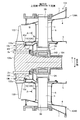
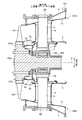
- FIG. 2 is a cross-sectional view of the exhaust chamber in the gas turbine according to the embodiment of the present invention.
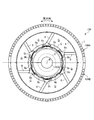
- FIG. 3 is an AA arrow view in FIG.
- FIG. 4A is a schematic view showing a tip shroud.
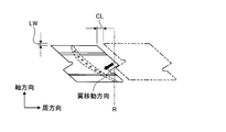
- FIG. 4B is a diagram illustrating a positional relationship between turbine blades.
- FIG. 5 is a perspective view of an exhaust chamber inlet side member in the gas turbine according to the first embodiment of the present invention.
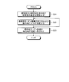
- FIG. 6 is a flowchart of a method of removing the last stage turbine rotor blade in the gas turbine according to the first embodiment of the present invention.
- FIG. 7 is a process diagram of a method of removing the last stage turbine rotor blade in the gas turbine according to the first embodiment of the present invention.
- FIG. 8 is a process diagram of a method for removing the last stage turbine rotor blade in the gas turbine according to the first embodiment of the present invention.
- FIG. 9 is a process diagram of a method for removing the last stage turbine rotor blade in the gas turbine according to the first embodiment of the present invention.
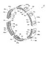
- FIG. 10 is a perspective view of an exhaust chamber inlet side member in the gas turbine according to the second embodiment of the present invention.
- FIG. 11 is a flowchart of a method of removing the last stage turbine rotor blade in the gas turbine according to the second embodiment of the present invention.
- FIG. 12 is a process diagram of a method for removing the last stage turbine rotor blade in the gas turbine according to the second embodiment of the present invention.
- FIG. 13 is a process diagram of a method for removing the last stage turbine rotor blade in the gas turbine according to the second embodiment of the present invention.
- FIG. 1 is a schematic configuration diagram of a gas turbine according to the present embodiment.
- the gas turbine 100 includes a compressor 101, a combustor 102, a turbine 103, an exhaust chamber 134, and a rotor 104 that is a rotating shaft. Further, the gas turbine 100 is arranged in the order of the compressor 101, the combustor 102, the turbine 103, and the exhaust chamber 134 along the axis R that is the center of the rotor 104 from the upstream side to the downstream side in the flow direction of the cooling air. Is arranged.
- the axial direction refers to a direction extending along the axis R and parallel to the axis R
- the radial direction refers to a direction orthogonal to the axis R
- the circumferential direction is centered on the axis R. As the circumferential direction perpendicular to the radial direction.
- Compressor 101 compresses air to generate compressed air.
- a compressor stationary blade 113 and a compressor moving blade 114 are provided in a compressor casing 112 having an air intake port 111 for taking in air.
- a plurality of compressor vanes 113 are attached to the compressor casing 112 side and arranged in the circumferential direction.
- a plurality of compressor blades 114 are attached to the rotor 104 side and arranged in the circumferential direction.
- the compressor stationary blades 113 and the compressor rotor blades 114 are alternately provided in the axial direction.
- the combustor 102 generates high-temperature and high-pressure combustion gas by supplying fuel to the compressed air compressed by the compressor 101.
- a plurality of (for example, 16) combustors 102 are arranged in a ring shape around the rotor 104 that is a rotating shaft.
- the turbine 103 generates rotational power by the combustion gas generated by the combustor 102.
- a turbine stationary blade 132 and a turbine rotor blade 133 are provided in a casing casing 131.
- a plurality of turbine vanes 132 are attached to the casing casing 131 side and arranged in the circumferential direction.
- a plurality of turbine rotor blades 133 are attached to the rotor 104 side and arranged in the circumferential direction.
- These turbine stationary blades 132 and turbine rotor blades 133 are provided alternately along the axial direction.
- the rotor 104 is rotatably provided about the axis R with the end on the compressor 101 side supported by the bearing 141 and the end on the exhaust chamber 134 supported by the bearing 142.
- the rotor 104 is connected to a drive shaft of a generator (not shown) at the end on the compressor 101 side.
- the air taken in from the air intake port 111 of the compressor 101 is compressed by passing through a plurality of compressor stationary blades 113 and compressor blades 114, thereby compressing at a high temperature and high pressure. It becomes air.
- the compressed air is mixed with fuel in the combustor 102 and burned, whereby high-temperature and high-pressure combustion gas is generated.
- the combustion gas passes through the turbine stationary blade 132 and the turbine rotor blade 133 of the turbine 103, so that the rotor 104 is rotationally driven. Electric power is generated by applying rotational power to the generator connected to the rotor 104.
- the combustion gas after rotationally driving the rotor 104 is discharged out of the system as exhaust gas in the exhaust chamber 134.
- FIG. 2 is a cross-sectional view of the exhaust chamber in the gas turbine according to the present embodiment
- FIG. 3 is a view taken along the line AA in FIG.
- the exhaust chamber 134 has a casing wall 1 that forms its outer shape.
- the exhaust chamber 134 includes a bearing cover 2 disposed on the radially inner side of the casing wall 1, and a strut 3 that connects the casing wall 1 and the bearing cover 2.
- the exhaust chamber 134 includes an outer diffuser 4 provided along the inner peripheral surface of the vehicle interior wall 1, an inner diffuser 5 provided along the outer peripheral surface of the bearing cover 2, which is further disposed on the radially inner side thereof, A strut cover 6 that connects the outer diffuser 4 and the inner diffuser 5 and covers the outer periphery of the strut 3 is provided.
- the casing wall 1 is a member that forms an outer shape of the exhaust chamber 134 in a cylindrical shape formed around the rotor 104 around the axis R.
- the vehicle interior wall 1 is disposed adjacent to the axial direction on the downstream side of the vehicle interior casing 131.
- the bearing cover 2 is a member that is disposed inside the casing wall 1 in the radial direction and has a cylindrical shape formed around the rotor 104 around the axis R.
- the bearing cover 2 supports the bearing portion 142 by accommodating the bearing portion 142 of the rotor 104 therein.
- the strut 3 has one end 3 ⁇ / b> A coupled to the outer peripheral surface of the bearing cover 2 and the other end 3 ⁇ / b> B coupled to the passenger compartment wall 1. That is, the casing wall 1 and the bearing cover 2 are connected by the strut 3.
- the strut 3 extends from the one end 3A to the other end 3B so as to incline in a tangential direction around the axis R as it goes radially outward, and a plurality of struts 3 (six in this embodiment) are spaced apart in the circumferential direction. ) Is provided.
- the outer diffuser 4 is provided along the inner peripheral surface of the passenger compartment wall 1 on the radially inner side of the passenger compartment wall 1 and has a substantially cylindrical shape formed in an annular shape around the rotor 104 around the axis R. It is a member.
- the outer diffuser 4 is penetrated by the strut 3.
- the inner diffuser 5 is provided along the outer peripheral surface of the bearing cover 2 on the outer side in the radial direction of the bearing cover 2, and is a member having a substantially cylindrical shape formed in an annular shape around the rotor 104 around the axis R. .
- the inner diffuser 5 is penetrated by the strut 3.
- the cylindrical space surrounded by the inner diffuser 5 and the outer diffuser 4 forms a combustion gas passage G through which the combustion gas passes.
- the dynamic pressure of the combustion gas after the rotor 104 is driven to rotate can be reduced. It has a function to convert pressure.
- the strut cover 6 is a member that covers the outer periphery of the strut 3, and has a function of taking cooling air from the outside of the exhaust chamber 134 and flowing the cooling air around the outer periphery of the strut 3 to cool the strut 3.
- the cooling air that has cooled the strut 3 cools internal members such as the bearing cover 2 and is discharged to the combustion gas passage G.
- six struts 3 are arranged and each is covered with a strut cover 6 to connect the outer diffuser 4 and the inner diffuser 5. Therefore, as shown in FIG. 3, the combustion gas passage G between the outer diffuser 4 and the inner diffuser 5 is also formed between the adjacent strut covers 6.
- the exhaust chamber 134 configured in this way is formed by dividing into two upper half parts 134A and lower half parts 134B on the horizontal plane with reference to the axis R (see FIG. 3). Further, the upstream end of the outer diffuser 4 faces the tip shroud at the tip of the final stage turbine blade 133 with respect to the final stage turbine blade 133 arranged on the most downstream side in the axial direction in the turbine 103, and the inner diffuser. 5 is opposed to the base end (blade root) of the final stage turbine rotor blade 133.
- the final stage turbine blade 133 is attached to a turbine disk 104 a in which a member on the radially inner side of the base end is formed integrally with the rotor 104.
- FIG. 4A is a schematic view showing the tip shroud in an assembled state
- FIG. 4B is a view showing the positional relationship of the turbine rotor blades in the process of removing the turbine rotor blades.
- the tip shrouds 133b adjacent to each other at the tip of the blades are formed in a hook shape with a predetermined gap between the adjacent dividing surfaces 133c in the circumferential direction.
- the contact surface 133d is formed at the central portion in the axial direction of the dividing surface 133c and having an inclination with respect to the axial direction so that the chip shrouds 133b come into contact with each other.
- a contact surface circumferential length L larger than the circumferential maximum clearance CL may be provided in order to maintain the contact length of the contact surface 133d.
- the circumferential maximum clearance CL is defined by moving the proximal end portions (blade root portions 133a) of adjacent blades slightly in the circumferential direction by the clearance of the blade root portion 133a. This refers to the maximum clearance formed on the dividing surface 133c of 133b. In the case of such a blade, as shown in FIG.
- the predetermined turbine blade 133 is moved along the contact surface 133d in a direction away from the reference blade in the circumferential direction with respect to the reference final stage turbine blade 133.
- the predetermined turbine blade 133 moves by the maximum clearance CL in the circumferential direction, and moves by the axial movement distance LW downstream in the axial direction.
- the adjacent turbine blades 133 are moved one after another by the same operation, and the turbine blades 133 arranged on the entire circumference in the circumferential direction are moved, so that the blade can be taken out from the base end portion (blade root portion 133a). It becomes.
- the blade root axial width W axial dimension
- the cumulative length of the axial movement distance LW of the adjacent last stage turbine blade 133 that makes one turn in the circumferential direction from the reference blade is the blade root portion. If the axial width W (axial dimension) is exceeded, all the final stage turbine blades 133 can be taken out.
- each turbine blade 133 is moved little by little along the contact surface 133d in the axial direction and the circumferential direction, and the entire turbine blade 133 is moved so as to be pushed in the downstream direction in the axial direction, the blades can be removed. Is possible.
- slide movement the operation of moving the turbine rotor blade 133 in the circumferential direction and the axial direction along the contact surface 133d of the tip shroud 133b is referred to as slide movement.
- the rotor (rotary shaft) 104 is rotated to move the final stage turbine rotor blade to a predetermined position (for example, the highest position in the circumferential direction), and the turbine operation is performed at the predetermined position.
- the slide movement of the wing may be performed.
- FIG. 5 is a perspective view of an exhaust chamber inlet side member in the gas turbine according to the present embodiment.
- the exhaust chamber inlet side member 10 is provided as an upstream end portion of the inner diffuser 5 and is configured to be detachable from the inner diffuser 5.
- the exhaust chamber inlet side member 10 is a cylindrical member formed in an annular shape around the rotor 104 around the axis R.
- the exhaust chamber inlet side member 10 is formed in an annular shape at a portion that is an inlet for the flow of combustion gas (exhaust gas) in the exhaust chamber 134 and an outlet for the flow of combustion gas from the turbine 103. It is also called the entrance ring.
- the exhaust chamber inlet side member 10 is formed such that its axial dimension (width) is larger than the axial dimension of the blade root 133a of the final stage turbine rotor blade 133.
- the exhaust chamber 134 is formed in an annular shape with respect to the axis R of the rotor (rotating shaft) 104, and is formed by dividing the upper half portion 134A and the lower half portion 134B into two in a horizontal plane (see FIGS. 2 and 3). ). Further, as shown in FIG. 5, the exhaust chamber inlet side member 10 is also formed in an annular shape with respect to the axis R of the rotor (rotating shaft) 104, and is divided into two parts, an upper half member 10A and a lower half member 10B, on a horizontal plane. Is formed.
- the upper half member 10A and the lower half member 10B are fastened by the circumferential fastening means 20 at the mutually divided portions.
- the circumferential fastening means 20 is configured by bolts and nuts extending along the axial direction and penetrating along the circumferential direction with respect to the rib 10a protruding radially inward.
- the upper half member 10 ⁇ / b> A and the lower half member 10 ⁇ / b> B are connected to each other in a ring shape by the ribs 10 a being fastened by the circumferential fastening means (bolts and nuts) 20.
- the upper half member 10A and the lower half member 10B are fastened to the inner diffuser 5 by the axial fastening means 21 as shown in FIGS. That is, as shown in FIG. 2 and FIG. 3, a rib (ridge part) 5 b that protrudes radially inward along the circumferential direction is provided at the upstream end in the axial direction on the inner diffuser 5 side. A rib 10b protruding radially inward along the circumferential direction is provided so as to face the rib 5b in the axial direction at the axially downstream end on the side.
- the axial fastening means 21 is composed of bolts and nuts.
- the upper half member 10 ⁇ / b> A and the lower half member 10 ⁇ / b> B are formed with openings 10 c so that the circumferential fastening means 20 and the axial fastening means 21 can be accessed from the outside in the radial direction.
- the opening 10c is closed by a lid member (not shown) during operation of the gas turbine 100.
- the rib (bump) 5 b attached to the inner diffuser 5 has an inner circumferential end along the circumferential direction of the rib 5 b corresponding to the circumferential position of the strut 3.
- a notch 5h that is recessed radially outward from the radially inner peripheral end is formed.
- the rib 10b adjacent to the upstream side in the axial direction of the rib 5b is located at a position corresponding to the circumferential position of the notch 5h along the circumferential direction at the radially inner peripheral end.
- a notch 10h is formed.
- the notch 5h and the notch 10h are notches penetrating in the axial direction of substantially the same size.
- the notch portion 5 h and the notch portion 10 h are provided, so that the cooling air flowing in the strut cover 6 flows upstream in the axial direction toward the exhaust chamber inlet side member 10. In the process of flowing, the flow of the cooling air is not disturbed because it flows through the notch 5h and the notch 10h without being obstructed by the rib 5b and the rib 10b.
- the upper half member 10A and the lower half member 10B of the exhaust chamber inlet side member 10 connected to the inner diffuser 5 are upstream end portions of the inner diffuser 5 as a part of the inner diffuser 5 as shown in FIG.
- the combustion gas passage G is formed together with the outer diffuser 4 to constitute the exhaust chamber 134 of the gas turbine 100.
- the exhaust chamber inlet side member 10 has an adjustment plate 10d as shown in FIGS.
- the adjustment plate 10d protrudes inward in the radial direction on the upstream side in the axial direction, is provided in an annular shape around the rotor 104, and a plurality of opening holes 10e are arranged in the circumferential direction.
- the exhaust chamber inlet side member 10 has a sealing portion 10f. The sealing portion 10f is provided at the protruding end of the adjustment plate 10d and abuts against a cover member 2a connected to a bearing cover 2 provided on the radially inner side of the inner diffuser 5 to thereby provide a radially inner space. It is to be sealed.
- the adjusting plate 10d has a function of reducing the amount of cooling air when the cooling air flowing on the outer periphery of the strut 3 is discharged to the combustion gas passage G. Thereby, even if the gas pressure of the combustion gas passage G varies in the circumferential direction, the amount of cooling air discharged from the opening hole 10e is reduced to some extent, so that the amount of cooling air discharged into the combustion gas varies in the circumferential direction. It is possible to prevent the combustion gas flow from being disturbed. Further, the sealing portion 10f prevents the combustion gas from entering the bearing portion 142 side of the inner diffuser 5.
- FIG. 6 is a flowchart of a method for removing the last stage turbine rotor blade in the gas turbine according to the present embodiment.
- 7 to 9 are process diagrams of a method for removing the last stage turbine rotor blade in the gas turbine according to the present embodiment.
- the exhaust chamber inlet side member 10 is removed from the inner diffuser 5 when the final stage turbine blade 133 is taken out.
- the circumferential fastening means (bolts and nuts) 20 are removed, and the connection between the upper half member 10A and the lower half member 10B of the exhaust chamber inlet side member 10 is disconnected (step S1).
- the upper half 134A of the exhaust chamber 134 is cut off from the lower half 134B, and the upper half of the exhaust chamber 134 is opened (step S2). Specifically, as shown in FIGS. 2 and 7, the upper half portion 134 ⁇ / b> A of the exhaust chamber 134, from the state shown in FIG. 2, the vehicle compartment wall 1, the outer diffuser 4, the strut 3, and the strut cover described above. 6. Remove the inner diffuser 5, the bearing cover 2, and the bearing portion 142. FIG. 7 shows a state where the upper half compartment is opened.
- the upper half member 10 ⁇ / b> A of the exhaust chamber inlet side member 10 may be removed integrally with the inner diffuser 5, or may be separated from the inner diffuser 5 by removing the bolt that is the axial fastening means 21.
- the lower half compartment of the exhaust chamber 134 is installed, and the compartment wall 1 of the lower half compartment, the outer diffuser 4, the strut 3, the strut cover 6, the inner diffuser 5, the bearing cover 2, and The bearing portion 142 is in a state where it is assembled to the lower half portion 134B. Therefore, the rotor 104 is rotatably supported.
- the axial fastening means (bolts and nuts) 21 shown in FIG. 5 for fixing the lower half member 10B to the inner diffuser 5 are removed, and as shown in FIG. 8, the exhaust chamber inlet side shown in FIG.
- the lower half member 10B of the member 10 is separated from the inner diffuser 5 and removed from the lower half portion 134B of the exhaust chamber 134 (step S3).
- a portion surrounded by a one-dot chain line in FIG. 8 indicates a corresponding portion in step S3.
- the lower half member 10B of the exhaust chamber inlet side member 10 separated from the inner diffuser 5 is rotated in the circumferential direction around the axis R and is extracted from the upper half of the opened exhaust chamber 134.
- step S4 all the final stage turbine blades 133 are slid little by little along the axis R from the state shown in FIG. Remove from the unit (step S4).
- the part enclosed with the dashed-dotted line of FIG. 9 shows the applicable location of step S4.
- the final stage turbine blade 133 is removed downstream in the axial direction (step S5).
- the drawn last stage turbine blade 133 is taken out from the upper half of the opened exhaust chamber 134.
- the tip end portions (chip shrouds 133 b) adjacent to each other in the circumferential direction are removed by opening the downstream side in the axial direction of each final stage turbine rotor blade 133 by being removed from the inner diffuser 5. Even if the last stage turbine blades 133 are meshed with each other, all the last stage turbine blades 133 are slid little by little in the axial direction and removed from the base end of the turbine disk 104a. Can do. As a result, the final stage turbine rotor blade 133 can be easily taken out by removing only the upper half part 134A without removing the entire exhaust chamber 134.
- exhaust chamber inlet side member 10 of the present embodiment is divided into at least an upper half member 10A and a lower half member 10B in the circumferential direction so as to be easily disassembled and assembled.
- the upper half member 10A when removing the upper half portion 134A of the exhaust chamber 134, the upper half member 10A can be removed as a unit.
- the upper half member 10A of the exhaust chamber inlet side member 10 is removed together with the upper half portion 134A of the exhaust chamber 134, and the lower half member 134 of the exhaust chamber inlet side member 10 is removed from the lower half portion 134B of the exhaust chamber 134 left thereafter. 10B can be removed. Therefore, it is possible to reduce the number of parts to be removed and reduce the work time for taking out the final stage turbine blade 133.
- the axial width of the exhaust chamber inlet side member 10 of the present embodiment is formed to have an axial dimension that is at least larger than the axial dimension (blade root axial width W) of the blade root 133a in the final stage turbine rotor blade 133. ing.
- each final stage turbine blade 133 when the axial downstream side of each final stage turbine blade 133 is opened by being removed from the inner diffuser 5, the final stage turbine blade 133 is slid to the downstream side in the axial direction.
- the region to be secured can be secured, and the final stage turbine rotor blade 133 can be reliably taken out.
- the exhaust chamber inlet side member 10 of the present embodiment is divided into an axial fastening means 21 fastened in the axial direction with respect to the inner diffuser 5 on the radial inner side of the inner diffuser 5 and a circumferential direction on the radial inner side. And a circumferential fastening means 20 fastened to each other, and an opening 10c formed so as to communicate (access to) each fastening means from the outside in the radial direction.
- the axial direction fastening means 21 and the circumferential direction fastening means 20 are arranged on the radially inner side of the inner diffuser 5.
- the opening 10 c is used.
- Each fastening means is operated from outside in the radial direction via
- the axial fastening means 21 and the circumferential fastening means 20 are disposed radially inward from the inner diffuser 5 and there are no obstacles in the combustion gas passage G. Therefore, the flow of the combustion gas is not disturbed, A situation that adversely affects the operation of the turbine 103 can be prevented.
- the present embodiment is for obtaining the effect of easily taking out the final stage turbine blade 133 with respect to the first embodiment described above. Therefore, in the present embodiment, the same reference numerals are given to the same portions as those in the first embodiment, and the description thereof will be omitted, and only the portions improved from the first embodiment will be described by adding new symbols.
- FIG. 10 is a perspective view of an exhaust chamber inlet side member in the gas turbine according to the present embodiment.
- the exhaust chamber inlet side member 10 is formed in an annular shape around the rotor 104, and is divided into a plurality of portions in the circumferential direction so as to be able to pass through the combustion gas passage G between the struts 3 (strut covers 6).
- the exhaust chamber inlet side member 10 is formed by being divided into an upper half member 10A and a lower half member 10B in a horizontal plane with respect to the axis R of the rotation axis, and the upper half member 10A and the lower half member 10B is divided into three equal parts and formed as divided members 10Aa, 10Ab, 10Ac, 10Ba, 10Bb, 10Bc in six equal parts in the circumferential direction.
- the divided members 10Aa, 10Ab, 10Ac, 10Ba, 10Bb, 10Bc are fastened by the circumferential fastening means 20 at the mutual divided portions.
- the circumferential fastening means 20 is constituted by bolts and nuts penetrating along the circumferential direction with respect to the rib 10a extending along the axial direction and projecting radially inward in each divided member.
- the dividing members 10Aa, 10Ab, 10Ac, 10Ba, 10Bb, and 10Bc are connected to each other in a ring shape by the ribs 10a being fastened by the circumferential fastening means (bolts and nuts) 20.
- the divided members 10Aa, 10Ab, 10Ac, 10Ba, 10Bb, and 10Bc are fastened to the inner diffuser 5 by the axial fastening means 21 as shown in FIGS.
- the axial fastening means 21 is composed of bolts and nuts, and on the inner diffuser 5 side, protrudes radially inward in the circumferential direction along the circumferential direction, and an exhaust chamber inlet side member. It is constituted by axial fastening means (bolts, nuts) 21 penetrating along the axial direction with respect to the rib 10b protruding radially inward along the circumferential direction so as to face the rib 5b in the axial direction on the 10th side.
- the divided members 10 ⁇ / b> Aa, 10 ⁇ / b> Ab, 10 ⁇ / b> Ac, 10 ⁇ / b> Ba, 10 ⁇ / b> Bb, and 10 ⁇ / b> Bc are connected to the inner diffuser 5 with the ribs 5 b and the ribs 10 b being fastened by the axial fastening means (bolts and nuts) 21. Further, as shown in FIG.
- the divided members 10 ⁇ / b> Aa, 10 ⁇ / b> Ab, 10 ⁇ / b> Ac, 10 ⁇ / b> Ba, 10 ⁇ / b> Bb and 10 ⁇ / b> Bc have an opening 10 c so that the circumferential fastening means 20 and the axial fastening means 21 can be accessed from the radially outer side. Is formed.
- the opening 10c is closed by a lid member (not shown) during operation of the gas turbine 100.
- the divided members 10Aa, 10Ab, 10Ac, 10Ba, 10Bb, 10Bc of the exhaust chamber inlet side member 10 connected to the inner diffuser 5 are part of the inner diffuser 5 as shown in FIG.
- An upstream end portion is formed, and a combustion gas passage G is formed together with the outer diffuser 4 to constitute an exhaust chamber 134 of the gas turbine 100.
- the exhaust gas adjacent to the upstream side in the axial direction of the rib (rib) 5b provided at the upstream end in the axial direction of the inner diffuser 5 is used.
- a notch 10 h is formed in the rib 10 b of the chamber inlet side member 10 along the circumferential direction at the radially inner peripheral end.
- the position in the circumferential direction of the notch 10h corresponds to the position in the circumferential direction of the notch 5h, and corresponds to the position in the circumferential direction of the strut 3 as in the first embodiment.
- FIG. 11 is a flowchart of a method for removing the last stage turbine rotor blade in the gas turbine according to the present embodiment.
- 12 and 13 are process diagrams of a method for removing the last stage turbine rotor blade in the gas turbine according to the present embodiment.
- the exhaust chamber inlet side member 10 is removed from the inner diffuser 5 when the final stage turbine blade 133 is taken out.
- the circumferential fastening means (bolts, nuts) 20 and the axial fastening means (bolts, nuts) 21 are removed, and the exhaust chamber inlet side member 10 shown in FIG. 2 is divided.
- the members 10Aa, 10Ab, 10Ac, 10Ba, 10Bb, 10Bc are removed from the inner diffuser 5 and taken out from the downstream side in the axial direction of the exhaust chamber 134 through the strut 3 (strut cover 6) (step S21).
- the part enclosed with the dashed-dotted line of FIG. 12 shows the applicable location of step S21.
- the casing wall 1, the outer diffuser 4, the strut 3, the strut cover 6, the inner diffuser 5, the bearing cover 2, and the bearing portion 142 that constitute the casing of the exhaust chamber 134 are left in the exhaust chamber 134 as they are.
- the cabin is not open. For this reason, the state which supported the rotor 104 rotatably is maintainable.
- the final stage turbine rotor blade 133 is arranged with the tip portions (chip shrouds 133b) adjacent to each other in the circumferential direction being arranged, but by adjusting the clearance of the blade root portion 133a, The turbine rotor blade 133 can be removed from the base end by slidingly moving the blade little by little along the blade contact surface 133d of the tip shroud 133b and successively moving adjacent blades.
- the drawn last stage turbine blade 133 is taken out from the downstream side in the axial direction of the exhaust chamber 134 through the combustion gas passage G between the struts 3 (strut cover 6).
- the tip end portions (chip shrouds 133 b) adjacent to each other in the circumferential direction are removed by opening the downstream side in the axial direction of each final stage turbine rotor blade 133 by being removed from the inner diffuser 5. Even if the last stage turbine blades 133 are meshed with each other, all the last stage turbine blades 133 are slid little by little in the axial direction and removed from the base end of the turbine disk 104a. Can do. As a result, the final stage turbine blade 133 can be easily taken out without opening the exhaust chamber 134.
- the exhaust chamber inlet side member 10 of the present embodiment is formed in an annular shape around the rotor (rotating shaft) 104 and has a size that can pass through the combustion gas passage G between the struts 3. It is formed in the axial width of the member 10 or is divided into a plurality in the circumferential direction.
- the exhaust chamber inlet side member 10 is divided into a plurality of portions in the axial width or circumferential direction of the exhaust chamber inlet side member 10 so as to be able to pass through the combustion gas passage G between the struts 3.
- the exhaust chamber 134 can be taken out from the downstream side in the axial direction of the exhaust chamber 134 without opening the exhaust chamber 134. That is, the exhaust chamber inlet side member 10 and the final stage turbine rotor blade 133 can be taken out while leaving the exhaust chamber 134.
- the number of parts to be removed can be further reduced as compared with the first embodiment, and the working time for taking out the final stage turbine blade 133 can be further reduced.
- the present invention is not limited to this example.
- the same concept can be applied to at least an example in which the entire exhaust chamber inlet side member 10 is divided into three or more in the circumferential direction.
- the other structures are the same as those in the first embodiment, and the operations and effects are the same as those in the first embodiment. .
Landscapes
- Engineering & Computer Science (AREA)
- Mechanical Engineering (AREA)
- General Engineering & Computer Science (AREA)
- Chemical & Material Sciences (AREA)
- Combustion & Propulsion (AREA)
- Supercharger (AREA)
- Turbine Rotor Nozzle Sealing (AREA)
- Structures Of Non-Positive Displacement Pumps (AREA)
Abstract
Description
本実施形態では、タービンディスク104aから最終段タービン動翼133を取り外すための排気室入口側部材、排気室、ガスタービンおよび最終段タービン動翼の取外しおよび取出方法について説明する。
本実施形態は、上述した実施形態1に対し、最終段タービン動翼133を容易に取り出す効果をより顕著に得るためのものである。従って、本実施形態では、上述した実施形態1と同一の部分に同一の符号を付して説明を省略し、実施形態1から改良された部分にのみ新たな符号を付して説明する。
2 軸受カバー
3 ストラット
4 外側ディフューザ
5 内側ディフューザ
5b リブ(鍔部)
5h 切欠き部
6 ストラットカバー
10 排気室入口側部材
10A 上半部材
10B 下半部材
10a リブ
10b リブ
10c 開口部
10d 調整板
10e 開口穴
10f 封止部
10h 切欠き部
10Aa,10Ab,10Ac,10Ba,10Bb,10Bc 分割部材
20 周方向締結手段
21 軸方向締結手段
100 ガスタービン
101 圧縮機
102 燃焼器
103 タービン
104 ロータ(回転軸)
133 最終段タービン動翼
133a 翼根部(基端部)
133b チップシュラウド
133c 分割面
133d 当り面
134 排気室
134A 上半部
134B 下半部
142 軸受部
G 燃焼ガス通路
R 軸線
Claims (13)
- 回転軸廻りに複数設けられているとともに前記回転軸が延在する軸方向に複数段設けられて前記回転軸とともに回転するタービン動翼を備えるタービンに対し、
当該タービンの下流側に隣接して配置されて前記回転軸の軸線を中心として円筒状に形成された車室壁と、
前記車室壁の内周面に沿って設けられて前記回転軸廻りに環状に形成された外側ディフューザと、
前記外側ディフューザの径方向の内側に配置されて前記外側ディフューザとの間で燃焼ガス通路を形成する環状の内側ディフューザと、
前記外側ディフューザと前記内側ディフューザの間で周方向に複数配置されて前記回転軸の軸受部を覆う環状の軸受カバーと前記車室壁の間を接続するストラットと、
を備え、
周方向に上半部と下半部とに分割された排気室の入口側に設けられる排気室入口側部材であって、
該排気室入口側部材は、軸方向の最も下流側に配置された最終段タービン動翼の基端部に対して軸方向下流側の対向する位置において前記内側ディフューザの一部を形成するように前記回転軸廻りに環状に形成され、かつ周方向に分割されて前記内側ディフューザに対して着脱可能に設けられていることを特徴とする排気室入口側部材。 - 周方向において少なくとも上半部材と下半部材とに分割されていることを特徴とする請求項1に記載の排気室入口側部材。
- 前記ストラットの間に形成された前記燃焼ガス通路を通過し得る大きさで周方向において複数に分割されていることを特徴とする請求項1または2に記載の排気室入口側部材。
- 少なくとも前記最終段タービン動翼における翼根部の軸方向寸法よりも大きい軸方向寸法に形成されていることを特徴とする請求項1~3のいずれか一つに記載の排気室入口側部材。
- 径方向内側において前記内側ディフューザに対して軸方向で締結される軸方向締結手段と、
径方向内側において周方向に分割された分割部材の相互間が周方向に締結される周方向締結手段と、
径方向外側から各前記締結手段に通じるように形成された開口部と、
を有することを特徴とする請求項1~4のいずれか一つに記載の排気室入口側部材。 - 軸方向下流側の端部において、径方向内側に突出して環状に形成された鍔部が設けられ、該鍔部の径方向内周端には前記ストラットの周方向位置に対応した位置に前記鍔部の周方向に沿った切欠き部を有することを特徴とする請求項1~5のいずれか一つに記載の排気室入口側部材。
- 軸方向上流側において径方向内側に突出して設けられて周方向に複数の開口穴が配列された調整板を有することを特徴とする請求項1~6のいずれか一つに記載の排気室入口側部材。
- 前記調整板の突出端に設けられて径方向内側の空間をシールする封止部を有することを特徴とする請求項7に記載の排気室入口側部材。
- 回転軸廻りに複数設けられているとともに前記回転軸が延在する軸方向に複数段設けられて前記回転軸とともに回転するタービン動翼を備えるタービンに対し、当該タービンの下流側に隣接して配置されて前記回転軸の軸線を中心として円筒状に形成された車室壁と、
前記車室壁の内周面に沿って設けられて前記回転軸廻りに環状に形成された外側ディフューザと、
前記外側ディフューザの径方向の内側に配置されて前記外側ディフューザとの間で燃焼ガス通路を形成する環状の内側ディフューザと、
前記外側ディフューザと前記内側ディフューザの間で周方向に複数配置されて前記回転軸の軸受部を覆う環状の軸受カバーと前記車室壁の間を接続するストラットと、
請求項1~8のいずれか一つに記載の排気室入口側部材と、
を備えることを特徴とする排気室。 - 圧縮機で圧縮した圧縮空気に燃焼器で燃料を供給して燃焼させ、発生した燃焼ガスをタービンに送って回転軸の回転動力を得て、前記タービンの下流側に至る燃焼ガスを排気室から排出するガスタービンにおいて、
請求項9に記載の排気室が適用されることを特徴とするガスタービン。 - 回転軸廻りに複数設けられているとともに前記回転軸が延在する軸方向に複数段設けられて前記回転軸とともに回転するタービン動翼を備えるタービンに対し、
当該タービンの下流側に隣接して配置されて前記回転軸の軸線を中心として円筒状に形成された車室壁と、
前記車室壁の内周面に沿って設けられて前記回転軸廻りに環状に形成された外側ディフューザと、
前記外側ディフューザの径方向の内側に配置されて前記外側ディフューザとの間で燃焼ガス通路を形成する環状の内側ディフューザと、
前記外側ディフューザと前記内側ディフューザの間で周方向に複数配置されて前記回転軸の軸受部を覆う環状の軸受カバーと前記車室壁の間を接続するストラットと、
を備える排気室が設けられたガスタービンにおける軸方向の最も下流側に配置された最終段タービン動翼を取り出す最終段タービン動翼取出方法であって、
前記排気室の上半部を取り外す工程と、
最終段タービン動翼の基端部に軸方向下流側で対向する位置において前記内側ディフューザの一部を形成するように、前記回転軸廻りに環状に形成されて周方向において少なくとも上半部材と下半部材に分割された排気室入口側部材のうちの下半部材を、前記排気室の下半部における前記内側ディフューザから取り外す工程と、
前記排気室入口側部材の前記下半部材を前記排気室の開放部分から取り出す工程と、
前記排気室入口側部材を取り外すことで軸方向下流側が開放された全ての前記最終段タービン動翼のうちの周方向の所定位置にある前記最終段タービン動翼を軸方向にスライド移動させ、各前記最終段タービン動翼を取り外す工程と、
取り外された前記最終段タービン動翼を前記排気室の上半部の開放部分から取り出す工程と、
を含むことを特徴とする最終段タービン動翼取出方法。 - 回転軸廻りに複数設けられているとともに前記回転軸が延在する軸方向に複数段設けられて前記回転軸とともに回転するタービン動翼を備えるタービンに対し、
当該タービンの下流側に隣接して配置されて前記回転軸の軸線を中心として円筒状に形成された車室壁と、
前記車室壁の内周面に沿って設けられて前記回転軸廻りに環状に形成された外側ディフューザと、
前記外側ディフューザの径方向の内側に配置されて前記外側ディフューザとの間で燃焼ガス通路を形成する環状の内側ディフューザと、
前記外側ディフューザと前記内側ディフューザの間で周方向に複数配置されて前記回転軸の軸受部を覆う環状の軸受カバーと前記車室壁の間を接続するストラットと、
を備え、周方向に上半部と下半部とに分割された排気室が設けられたガスタービンにおける軸方向の最も下流側に配置された最終段タービン動翼を取り出す最終段タービン動翼取出方法であって、
最終段タービン動翼の基端部に対して軸方向下流側で対向する位置において前記内側ディフューザの一部を形成するように、前記回転軸廻りに環状に形成されて前記ストラットの間に形成された前記燃焼ガス通路を通過し得る大きさで周方向において複数に分割された排気室入口側部材を、前記内側ディフューザから取り外す工程と、
前記複数に分割された排気室入口側部材を、前記ストラットの間の燃焼ガス通路を通じて取り外す工程と、
前記最終段タービン動翼をスライド移動させ、各前記最終段タービン動翼を取り外す工程と、
取り外された前記最終段タービン動翼を前記ストラットの間であって前記燃焼ガス通路を通じて取り出す工程と、
を含むことを特徴とする最終段タービン動翼取出方法。 - 前記排気室入口側部材は、径方向内側において前記内側ディフューザに対して軸方向で締結される軸方向締結手段と、径方向内側において周方向に分割された分割部材の相互間が周方向に締結される周方向締結手段と、径方向外側から各前記締結手段に通じるように形成された開口部と、を有しており、
前記排気室入口側部材を前記内側ディフューザから取り外す工程では、前記開口部を通して径方向外側から各前記締結手段を操作することを特徴とする請求項11または12に記載の最終段タービン動翼取出方法。
Priority Applications (4)
| Application Number | Priority Date | Filing Date | Title |
|---|---|---|---|
| KR1020167022633A KR101821915B1 (ko) | 2014-03-14 | 2015-02-03 | 배기실 입구측 부재, 배기실, 가스 터빈 및 최종단 터빈 동익 취출 방법 |
| DE112015001259.1T DE112015001259T5 (de) | 2014-03-14 | 2015-02-03 | Abgaskammer-Einlassseitenelement, Abgaskammer, Gasturbine und Verfahren zum Entfernen einer Turbinenschaufel der letzten Stufe |
| US15/118,706 US10662819B2 (en) | 2014-03-14 | 2015-02-03 | Exhaust chamber inlet-side member, exhaust chamber, gas turbine, and last-stage turbine blade removal method |
| CN201580008663.0A CN106030049B (zh) | 2014-03-14 | 2015-02-03 | 排气室入口侧构件、排气室、燃气涡轮以及最末级涡轮动叶片取出方法 |
Applications Claiming Priority (2)
| Application Number | Priority Date | Filing Date | Title |
|---|---|---|---|
| JP2014052157A JP6203090B2 (ja) | 2014-03-14 | 2014-03-14 | 排気室入口側部材、排気室、ガスタービンおよび最終段タービン動翼取出方法 |
| JP2014-052157 | 2014-03-14 |
Publications (1)
| Publication Number | Publication Date |
|---|---|
| WO2015137010A1 true WO2015137010A1 (ja) | 2015-09-17 |
Family
ID=54071462
Family Applications (1)
| Application Number | Title | Priority Date | Filing Date |
|---|---|---|---|
| PCT/JP2015/053007 Ceased WO2015137010A1 (ja) | 2014-03-14 | 2015-02-03 | 排気室入口側部材、排気室、ガスタービンおよび最終段タービン動翼取出方法 |
Country Status (6)
| Country | Link |
|---|---|
| US (1) | US10662819B2 (ja) |
| JP (1) | JP6203090B2 (ja) |
| KR (1) | KR101821915B1 (ja) |
| CN (1) | CN106030049B (ja) |
| DE (1) | DE112015001259T5 (ja) |
| WO (1) | WO2015137010A1 (ja) |
Families Citing this family (11)
| Publication number | Priority date | Publication date | Assignee | Title |
|---|---|---|---|---|
| US10330011B2 (en) * | 2013-03-11 | 2019-06-25 | United Technologies Corporation | Bench aft sub-assembly for turbine exhaust case fairing |
| CN108005732B (zh) * | 2017-12-20 | 2024-04-19 | 华瑞(江苏)燃机服务有限公司 | 一种燃气轮机透平静叶组件的拆卸机构 |
| CN111727310B (zh) * | 2018-02-19 | 2022-07-08 | 株式会社Ihi | 涡轮 |
| JP7254472B2 (ja) * | 2018-09-28 | 2023-04-10 | 三菱重工業株式会社 | 蒸気タービンの排気室、蒸気タービン及び蒸気タービンの換装方法 |
| US11391179B2 (en) | 2019-02-12 | 2022-07-19 | Pratt & Whitney Canada Corp. | Gas turbine engine with bearing support structure |
| US11346249B2 (en) | 2019-03-05 | 2022-05-31 | Pratt & Whitney Canada Corp. | Gas turbine engine with feed pipe for bearing housing |
| CN110905605B (zh) * | 2019-12-17 | 2024-07-09 | 河北国源电气股份有限公司 | 一种汽轮机蒸汽导向控制装置 |
| CN112253547B (zh) * | 2020-10-22 | 2022-11-18 | 湖南南方通用航空发动机有限公司 | 一种转子叶片的分解方法 |
| US11448097B1 (en) * | 2021-05-27 | 2022-09-20 | Pratt & Whitney Canada Corp. | Turbine exhaust strut internal core structure |
| US11629615B2 (en) * | 2021-05-27 | 2023-04-18 | Pratt & Withney Canada Corp. | Strut reinforcing structure for a turbine exhaust case |
| JP7299945B2 (ja) * | 2021-06-04 | 2023-06-28 | 三菱重工業株式会社 | タービン車室、ガスタービン及び位置合わせ方法 |
Citations (4)
| Publication number | Priority date | Publication date | Assignee | Title |
|---|---|---|---|---|
| JP2005083199A (ja) * | 2003-09-04 | 2005-03-31 | Hitachi Ltd | ガスタービン設備及び冷却空気供給方法 |
| WO2013035391A1 (ja) * | 2011-09-09 | 2013-03-14 | 三菱重工業株式会社 | ガスタービン |
| US20130149107A1 (en) * | 2011-12-08 | 2013-06-13 | Mrinal Munshi | Gas turbine outer case active ambient cooling including air exhaust into a sub-ambient region of exhaust flow |
| WO2013128683A1 (ja) * | 2012-02-27 | 2013-09-06 | 三菱重工業株式会社 | ガスタービン |
Family Cites Families (5)
| Publication number | Priority date | Publication date | Assignee | Title |
|---|---|---|---|---|
| US5104286A (en) * | 1991-02-08 | 1992-04-14 | Westinghouse Electric Corp. | Recirculation seal for a gas turbine exhaust diffuser |
| DE4232088A1 (de) * | 1992-09-25 | 1994-03-31 | Asea Brown Boveri | Gasturbine mit Abgasgehäuse und Abgaskanal |
| JP4969500B2 (ja) * | 2008-03-28 | 2012-07-04 | 三菱重工業株式会社 | ガスタービン |
| JP5951187B2 (ja) * | 2011-03-29 | 2016-07-13 | 三菱重工業株式会社 | タービン排気構造及びガスタービン |
| JP6466647B2 (ja) | 2014-03-27 | 2019-02-06 | 三菱日立パワーシステムズ株式会社 | ガスタービンの分割環の冷却構造及びこれを有するガスタービン |
-
2014
- 2014-03-14 JP JP2014052157A patent/JP6203090B2/ja active Active
-
2015
- 2015-02-03 US US15/118,706 patent/US10662819B2/en active Active
- 2015-02-03 CN CN201580008663.0A patent/CN106030049B/zh active Active
- 2015-02-03 WO PCT/JP2015/053007 patent/WO2015137010A1/ja not_active Ceased
- 2015-02-03 KR KR1020167022633A patent/KR101821915B1/ko active Active
- 2015-02-03 DE DE112015001259.1T patent/DE112015001259T5/de active Pending
Patent Citations (4)
| Publication number | Priority date | Publication date | Assignee | Title |
|---|---|---|---|---|
| JP2005083199A (ja) * | 2003-09-04 | 2005-03-31 | Hitachi Ltd | ガスタービン設備及び冷却空気供給方法 |
| WO2013035391A1 (ja) * | 2011-09-09 | 2013-03-14 | 三菱重工業株式会社 | ガスタービン |
| US20130149107A1 (en) * | 2011-12-08 | 2013-06-13 | Mrinal Munshi | Gas turbine outer case active ambient cooling including air exhaust into a sub-ambient region of exhaust flow |
| WO2013128683A1 (ja) * | 2012-02-27 | 2013-09-06 | 三菱重工業株式会社 | ガスタービン |
Also Published As
| Publication number | Publication date |
|---|---|
| JP6203090B2 (ja) | 2017-09-27 |
| CN106030049B (zh) | 2017-08-01 |
| US20170067369A1 (en) | 2017-03-09 |
| KR20160108550A (ko) | 2016-09-19 |
| DE112015001259T5 (de) | 2016-12-01 |
| JP2015175287A (ja) | 2015-10-05 |
| CN106030049A (zh) | 2016-10-12 |
| US10662819B2 (en) | 2020-05-26 |
| KR101821915B1 (ko) | 2018-01-24 |
Similar Documents
| Publication | Publication Date | Title |
|---|---|---|
| JP6203090B2 (ja) | 排気室入口側部材、排気室、ガスタービンおよび最終段タービン動翼取出方法 | |
| US8727703B2 (en) | Gas turbine engine | |
| KR101182625B1 (ko) | 가스 터빈 | |
| RU2532479C2 (ru) | Турбореактивный двигатель, содержащий улучшенные средства регулирования расхода потока воздуха охлаждения, отбираемого с выхода компрессора высокого давления | |
| US10865658B2 (en) | Gas turbine exhaust member, and exhaust chamber maintenance method | |
| JP2015175287A5 (ja) | ||
| US9371737B2 (en) | Gas turbine | |
| US10844750B2 (en) | Method of disassembling and assembling gas turbine and gas turbine assembled thereby | |
| JP2013221513A (ja) | タービンブレードのブレード取り付け領域をカバーするためのシステムおよび方法 | |
| JP2016505111A (ja) | ガスタービンエンジンの内側シュラウドに溝を含むシール組立体 | |
| US10808609B2 (en) | Method of assembling and disassembling gas turbine and gas turbine assembled thereby | |
| JP2015045333A (ja) | ガスタービンシステムのためのインデューサおよびディフューザの構成 | |
| JP6586389B2 (ja) | 圧縮機ディフューザおよびガスタービン | |
| JP5495893B2 (ja) | ガスタービンおよびその改造方法 | |
| CN104769235A (zh) | 燃气涡轮发动机排气系统和进入涡轮叶片的方法 | |
| US11603775B2 (en) | Removable pin on a turbomachine nozzle | |
| US20250198305A1 (en) | Gas turbine engine with turbine vane carrier cooling flow path | |
| US11834953B2 (en) | Seal assembly in a gas turbine engine | |
| CN108661727A (zh) | 涡轮发动机轴承组件及其组装方法 | |
| JP7171297B2 (ja) | タービン排気ディフューザ | |
| JP2018516330A (ja) | 冷却フィンを備えたケーシングを有するガスタービンエンジン | |
| JP7496930B2 (ja) | ガスタービンの静翼組立体、静止部材セグメント及びガスタービンの静翼組立体の製造方法 | |
| JP2019163755A (ja) | 翼の取り外し方法及び支持リング |
Legal Events
| Date | Code | Title | Description |
|---|---|---|---|
| 121 | Ep: the epo has been informed by wipo that ep was designated in this application |
Ref document number: 15761330 Country of ref document: EP Kind code of ref document: A1 |
|
| WWE | Wipo information: entry into national phase |
Ref document number: 15118706 Country of ref document: US |
|
| ENP | Entry into the national phase |
Ref document number: 20167022633 Country of ref document: KR Kind code of ref document: A |
|
| WWE | Wipo information: entry into national phase |
Ref document number: 112015001259 Country of ref document: DE |
|
| 122 | Ep: pct application non-entry in european phase |
Ref document number: 15761330 Country of ref document: EP Kind code of ref document: A1 |