WO2015136927A1 - Heat-treatment device and heat-treatment method - Google Patents
Heat-treatment device and heat-treatment method Download PDFInfo
- Publication number
- WO2015136927A1 WO2015136927A1 PCT/JP2015/001334 JP2015001334W WO2015136927A1 WO 2015136927 A1 WO2015136927 A1 WO 2015136927A1 JP 2015001334 W JP2015001334 W JP 2015001334W WO 2015136927 A1 WO2015136927 A1 WO 2015136927A1
- Authority
- WO
- WIPO (PCT)
- Prior art keywords
- heat treatment
- workpiece
- pair
- cooling water
- peripheral surface
- Prior art date
Links
Images


Classifications
-
- C—CHEMISTRY; METALLURGY
- C21—METALLURGY OF IRON
- C21D—MODIFYING THE PHYSICAL STRUCTURE OF FERROUS METALS; GENERAL DEVICES FOR HEAT TREATMENT OF FERROUS OR NON-FERROUS METALS OR ALLOYS; MAKING METAL MALLEABLE, e.g. BY DECARBURISATION OR TEMPERING
- C21D9/00—Heat treatment, e.g. annealing, hardening, quenching or tempering, adapted for particular articles; Furnaces therefor
- C21D9/40—Heat treatment, e.g. annealing, hardening, quenching or tempering, adapted for particular articles; Furnaces therefor for rings; for bearing races
-
- C—CHEMISTRY; METALLURGY
- C21—METALLURGY OF IRON
- C21D—MODIFYING THE PHYSICAL STRUCTURE OF FERROUS METALS; GENERAL DEVICES FOR HEAT TREATMENT OF FERROUS OR NON-FERROUS METALS OR ALLOYS; MAKING METAL MALLEABLE, e.g. BY DECARBURISATION OR TEMPERING
- C21D1/00—General methods or devices for heat treatment, e.g. annealing, hardening, quenching or tempering
- C21D1/34—Methods of heating
- C21D1/42—Induction heating
-
- C—CHEMISTRY; METALLURGY
- C21—METALLURGY OF IRON
- C21D—MODIFYING THE PHYSICAL STRUCTURE OF FERROUS METALS; GENERAL DEVICES FOR HEAT TREATMENT OF FERROUS OR NON-FERROUS METALS OR ALLOYS; MAKING METAL MALLEABLE, e.g. BY DECARBURISATION OR TEMPERING
- C21D1/00—General methods or devices for heat treatment, e.g. annealing, hardening, quenching or tempering
- C21D1/62—Quenching devices
- C21D1/667—Quenching devices for spray quenching
-
- C—CHEMISTRY; METALLURGY
- C21—METALLURGY OF IRON
- C21D—MODIFYING THE PHYSICAL STRUCTURE OF FERROUS METALS; GENERAL DEVICES FOR HEAT TREATMENT OF FERROUS OR NON-FERROUS METALS OR ALLOYS; MAKING METAL MALLEABLE, e.g. BY DECARBURISATION OR TEMPERING
- C21D9/00—Heat treatment, e.g. annealing, hardening, quenching or tempering, adapted for particular articles; Furnaces therefor
- C21D9/0062—Heat-treating apparatus with a cooling or quenching zone
-
- H—ELECTRICITY
- H05—ELECTRIC TECHNIQUES NOT OTHERWISE PROVIDED FOR
- H05B—ELECTRIC HEATING; ELECTRIC LIGHT SOURCES NOT OTHERWISE PROVIDED FOR; CIRCUIT ARRANGEMENTS FOR ELECTRIC LIGHT SOURCES, IN GENERAL
- H05B6/00—Heating by electric, magnetic or electromagnetic fields
- H05B6/02—Induction heating
- H05B6/10—Induction heating apparatus, other than furnaces, for specific applications
- H05B6/101—Induction heating apparatus, other than furnaces, for specific applications for local heating of metal pieces
-
- H—ELECTRICITY
- H05—ELECTRIC TECHNIQUES NOT OTHERWISE PROVIDED FOR
- H05B—ELECTRIC HEATING; ELECTRIC LIGHT SOURCES NOT OTHERWISE PROVIDED FOR; CIRCUIT ARRANGEMENTS FOR ELECTRIC LIGHT SOURCES, IN GENERAL
- H05B6/00—Heating by electric, magnetic or electromagnetic fields
- H05B6/02—Induction heating
- H05B6/10—Induction heating apparatus, other than furnaces, for specific applications
- H05B6/105—Induction heating apparatus, other than furnaces, for specific applications using a susceptor
- H05B6/109—Induction heating apparatus, other than furnaces, for specific applications using a susceptor using magnets rotating with respect to a susceptor
-
- H—ELECTRICITY
- H05—ELECTRIC TECHNIQUES NOT OTHERWISE PROVIDED FOR
- H05B—ELECTRIC HEATING; ELECTRIC LIGHT SOURCES NOT OTHERWISE PROVIDED FOR; CIRCUIT ARRANGEMENTS FOR ELECTRIC LIGHT SOURCES, IN GENERAL
- H05B6/00—Heating by electric, magnetic or electromagnetic fields
- H05B6/02—Induction heating
- H05B6/10—Induction heating apparatus, other than furnaces, for specific applications
- H05B6/14—Tools, e.g. nozzles, rollers, calenders
-
- H—ELECTRICITY
- H05—ELECTRIC TECHNIQUES NOT OTHERWISE PROVIDED FOR
- H05B—ELECTRIC HEATING; ELECTRIC LIGHT SOURCES NOT OTHERWISE PROVIDED FOR; CIRCUIT ARRANGEMENTS FOR ELECTRIC LIGHT SOURCES, IN GENERAL
- H05B6/00—Heating by electric, magnetic or electromagnetic fields
- H05B6/02—Induction heating
- H05B6/36—Coil arrangements
- H05B6/42—Cooling of coils
-
- H—ELECTRICITY
- H05—ELECTRIC TECHNIQUES NOT OTHERWISE PROVIDED FOR
- H05B—ELECTRIC HEATING; ELECTRIC LIGHT SOURCES NOT OTHERWISE PROVIDED FOR; CIRCUIT ARRANGEMENTS FOR ELECTRIC LIGHT SOURCES, IN GENERAL
- H05B6/00—Heating by electric, magnetic or electromagnetic fields
- H05B6/02—Induction heating
- H05B6/36—Coil arrangements
- H05B6/44—Coil arrangements having more than one coil or coil segment
-
- Y—GENERAL TAGGING OF NEW TECHNOLOGICAL DEVELOPMENTS; GENERAL TAGGING OF CROSS-SECTIONAL TECHNOLOGIES SPANNING OVER SEVERAL SECTIONS OF THE IPC; TECHNICAL SUBJECTS COVERED BY FORMER USPC CROSS-REFERENCE ART COLLECTIONS [XRACs] AND DIGESTS
- Y02—TECHNOLOGIES OR APPLICATIONS FOR MITIGATION OR ADAPTATION AGAINST CLIMATE CHANGE
- Y02P—CLIMATE CHANGE MITIGATION TECHNOLOGIES IN THE PRODUCTION OR PROCESSING OF GOODS
- Y02P10/00—Technologies related to metal processing
- Y02P10/25—Process efficiency
Definitions
- the present invention relates to a heat treatment apparatus and a heat treatment method in which heat treatment is performed over the entire circumference of a circumferential surface of an annular workpiece.
- a method of surface hardening treatment for an annular member made of steel for example, quenching using a heating coil is used.
- a quenching device is known in which an annular member is heated using one or two heating coils, and then cooled and quenched.
- Patent Document 1 a hardened and hardened layer that is uniform over the entire circumference of the circumferential groove of the workpiece is obtained by heating and cooling the heated portion of the workpiece using two high-frequency induction heating coils.
- An induction hardening apparatus for forming a steel is disclosed.
- the outer periphery of the ring work is heated using two or more even number of movable high frequency inductors, and the coolant is ejected from the coolant ejection holes provided in the high frequency inductor.
- an induction hardening method is disclosed in which the ring work is cooled and quenched.
- JP 2010-222672 A Japanese Patent Publication No. 36-505
- the work in order to quench the work as a processing material, after heating the work so that the temperature becomes higher than the temperature at which the work becomes austenitic, the work becomes a temperature below the martensite start (Ms) point in the austenite state. It is necessary to cause the transformation of the work structure from austenite to martensite.
- Ms martensite start
- the workpiece cannot be quenched. Further, even if the workpiece can be heated once more than the temperature at which the workpiece becomes austenitic, if the workpiece is not properly cooled thereafter, the workpiece cannot be quenched. Furthermore, after the workpiece is heated and cooled, that is, after the workpiece is quenched, if the workpiece is heated again, annealing occurs and the surface layer of the workpiece is softened.
- the two moving cooling jackets for cooling the workpiece heated by the two high frequency induction heating coils at the position where the quenching of the ring-shaped workpiece is started Is considered to be installed between two high-frequency induction heating coils. Since two moving cooling jackets are installed between the two high-frequency induction heating coils, a space is created between the two high-frequency induction heating coils at the position where quenching is started. There was a problem that it was difficult to heat the workpiece to a temperature above which austenite was formed, and it was difficult to form a uniform hardened layer.
- the position where the annular workpiece is located is set.
- beginning of quenching quenching
- quenching finish the work at the portion where quenching is to be completed
- the present invention has been made in view of the above problems, and an object of the present invention is to provide a heat treatment apparatus and a heat treatment method capable of realizing that uniform heat treatment is performed over the entire circumference of the circumferential surface of the annular workpiece. Is to provide.
- a heat treatment apparatus includes a table on which an annular work can be placed, and a pair of heat treatment parts for heat-treating a peripheral surface of the work, and the pair of heat treatment parts includes the workpiece.
- the workpiece can be moved relative to the table by subjecting the workpiece to heat treatment while moving in the opposite directions along the circumferential surface.
- a pair of swivel arms heat-treats the peripheral surface of the work by swinging the pair of heat-treatment parts relative to the work.
- the heat treatment method according to the present invention uses a heat treatment apparatus including a table on which an annular work can be placed and a pair of heat treatment parts for heat-treating the peripheral surface of the work.
- a pair of swivel arms capable of relatively swiveling movement with respect to the workpiece the pair of heat treatment parts are swung relative to the workpiece to perform heat treatment, and then the pair of heat treatment parts are Heat treatment is performed over the entire circumference of the peripheral surface of the workpiece by performing heat treatment on the workpiece while moving in opposite directions along the peripheral surface of the workpiece.
- the heat treatment apparatus includes a table on which an annular workpiece can be placed, and a pair of heat treatment portions for heat treatment of the peripheral surface of the workpiece, the pair of heat treatment portions, A heat treatment apparatus used for obtaining a workpiece having a desired property by subjecting the workpiece to heat treatment while moving in opposite directions along the peripheral surface of the workpiece, wherein the heat treatment section includes A heating coil that can be disposed opposite to the peripheral surface of the workpiece, a first cooling water discharge portion that is provided in the heating coil and discharges cooling water, and is installed at a position overlapping the heating coil.
- a second cooling water discharge part for discharging cooling water so that when the pair of heat treatment parts move in opposite directions along the peripheral surface of the workpiece, the heating
- the peripheral surface of the workpiece heated by the cooling is sequentially cooled by the cooling water discharged from the first cooling water discharge portion and the pair of heat treatment processing portions move to adjacent positions, the workpiece is heated by the heating coil.
- heat treatment is performed over the entire periphery of the peripheral surface of the workpiece. it can.
- the heat treatment method according to the present invention can be disposed opposite to the work surface, a table on which an annular work can be placed, a pair of heat treatment parts for heat-treating the work surface.
- the pair of heat treatment processing portions perform heat treatment on the workpiece while moving in opposite directions along the peripheral surface of the workpiece, thereby obtaining desired properties.
- FIG. 1 is a schematic diagram illustrating a configuration example of a heat treatment apparatus according to the present embodiment.
- FIG. 2 is a schematic diagram for explaining an example of swinging operation of the heat treatment apparatus according to the present embodiment.
- FIG. 3 is a schematic diagram for explaining an example of the heat treatment operation of the heat treatment apparatus according to the present embodiment.
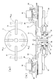
- FIG. 4 is a diagram illustrating an overall configuration example of an example of the heat treatment apparatus according to the present embodiment.
- FIG. 5 is a schematic diagram for explaining a table of an example of the heat treatment apparatus according to the present embodiment, and FIG. 5A is a plan view of the table of the example, and FIG. Part (b) is a side view of the table of this embodiment.
- FIG. 5 is a schematic diagram for explaining a table of an example of the heat treatment apparatus according to the present embodiment, and FIG. 5A is a plan view of the table of the example, and FIG. Part (b) is a side view of the table of this embodiment.
- FIG. 6 is a schematic view for explaining a heating coil of an example of the heat treatment apparatus according to the present embodiment.
- FIG. 7 is a perspective view including a partial cross section of the slewing bearing.
- FIG. 8 is a cross-sectional view of the slewing bearing.
- FIG. 9 is a schematic diagram illustrating a basic configuration example of the heat treatment apparatus according to the present embodiment.
- FIG. 10 is a schematic diagram illustrating a basic operation example of the heat treatment apparatus according to the present embodiment, in which a partial diagram (a) in the drawing is a schematic diagram illustrating a state of firing, and a partial diagram ( b) is a schematic diagram showing a state between the start and end of firing, and a partial diagram (c) and a partial diagram (d) in the drawing are schematic diagrams showing a state after the firing.
- FIG. 11 is a schematic diagram for explaining a state in which cooling water is discharged by the first cooling water discharge unit and the second cooling water discharge unit at the end of the heat treatment apparatus according to the present embodiment.
- FIG. 12 is a schematic diagram for illustrating various configuration examples of the heat treatment apparatus according to the present invention.
- FIG. 1 is a schematic diagram illustrating a configuration example of the heat treatment apparatus according to the present embodiment.
- the heat treatment apparatus 10 includes a table 11 on which an annular workpiece W can be placed, and a pair of heat treatment portions 20 ( 20a, 20b) and a pair of swivel arms 30 (30a, 30b) movable relative to the table 11.
- Work W is a processed material that is heat treated.
- the workpiece W in the present embodiment is, for example, an outer ring or an inner ring that constitutes a slewing bearing, and has a substantially rectangular shape or a substantially trapezoidal shape having a substantially U-shaped (substantially inverted L-shaped) notch in cross-sectional view. It has become.
- the workpiece W can be heat-treated on the rolling element rolling surface of the slewing bearing, for example.
- the table 11 is formed in a substantially circular shape in plan view, and can place the workpiece W thereon. Then, by placing and fixing the workpiece W on the table 11 by a crane 17 which will be described later, it is possible to perform a heat treatment process.
- the table 11 is configured to be rotatable about the center of the table 11 as a rotation center axis.
- the heat treatment part 20 (20a, 20b) is for heat-treating the peripheral surface of the workpiece W.
- the heating coil 21 (21a, 21b) for heating the workpiece W and the workpiece W are cooled.
- the heat treatment processing unit 20 is installed on the swivel arm 30 that can move relative to the table 11, and can perform heat treatment on the peripheral surface of the workpiece W.
- the heating coil 21 is configured so that it can be disposed opposite to the peripheral surface of the workpiece W. And the surrounding surface of the workpiece
- work W can be heated now. And in the heat processing apparatus 10 which concerns on this embodiment, the heating coil 21 is comprised so that it may install in the turning arm 30 mentioned later.
- the cooling water discharge part 23 is provided along with the heating coil 21 and can discharge cooling water. Then, for example, a plurality of holes can be formed in the side surface of the cooling water discharge portion 23 opposite to the side surface of the cooling water discharge portion 23 provided with the heating coil 21 to discharge the cooling water. Can do. Moreover, it is good also as being able to open a some hole in the surface facing the workpiece
- the swivel arm 30 is configured to be movable relative to the table 11, and the heat treatment processing unit 20 can be installed on the swivel arm 30.
- the heating coil 21 is installed on the turning arm 30.
- the swivel arm 30 allows the heat treatment processing unit 20 to move along the circumferential surface of the annular workpiece W, and to perform heat treatment on the circumferential surface of the workpiece W.
- the pair of turning arms 30 is configured to be able to swing with respect to the workpiece W.
- the cooling device 26 for cooling the work W after the heat treatment processing unit 20 is retracted from the burning end portion of the work W It is fixedly installed on the table 11 which is the end of baking.
- the cooling device 26 is installed, for example, facing a workpiece W that is an outer ring or an inner ring of a slewing bearing, and a plurality of holes are formed in a surface facing the workpiece W so that cooling water can be discharged. be able to.
- FIG. 2 is a schematic diagram for explaining an example of swinging operation of the heat treatment apparatus according to the present embodiment.
- FIG. 3 is a schematic diagram for explaining an example of the heat treatment operation of the heat treatment apparatus according to the present embodiment.
- the shaded portion indicates a portion of the workpiece W that has been heat-treated by the heat treatment apparatus 10 according to the present embodiment.
- a pair of heat treatment parts 20 (20a, 20b) are arranged adjacent to each other as shown in a partial diagram (a) of FIG. .
- release part 23 (23a, 23b) is each installed between a pair of heating coils 21 (21a, 21b)
- release part 23 ( 23a, 23b) is opposed to the peripheral surface of the workpiece W and is heated from the heating coil 21 (21a, 21b), which is located apart by the width dimension of the cooling water discharge part 23 (23a, 23b). It will be difficult. Further, it is not sufficient to heat the portion only by heat conduction in the heated workpiece W.
- the pair of swivel arms 30 (30a, 30b) is swung relative to the workpiece W to sufficiently heat the vicinity of the start position of the heat treatment process. Therefore, a suitable heat treatment process is performed.
- specific steps of the heat treatment method using the heat treatment apparatus 10 according to the present embodiment will be described.
- the pair of heat treatment parts 20 (20a, 20b) and the pair of swivel arms 30 (30a, 30b) shown in the partial diagram (a) of FIG. 2 are transferred to the workpiece W by the pair of heat treatment parts 20 (20a, 20b).
- the peripheral surface of the work W can be heated to a temperature higher than the temperature at which the work W becomes austenite by swinging in the left-right direction on the paper surface.
- a pair of heat processing part 20 (20a, 20b) and a pair of turning arm 30 (30a, 30b) are rock
- the peripheral surface of the workpiece W to be heated can be heated by the heating coil 21b included in the heat treatment part 20b on the right side of the drawing.
- the state shown by the solid line in FIG. In such a state, the cooling water discharge parts 23 (23a, 23b) included in the pair of heat treatment parts 20 (20a, 20b) shown in the partial diagram (d) of FIG.
- the peripheral surface of the workpiece W can be heated by a heating coil 21a included in the heat treatment part 20a on the left side of the drawing.
- the pair of heat treatment parts 20 (20a, 20b) and the pair of swivel arms 30 (30a, 30b) are swung in the left direction on the sheet and then are swung in the right direction on the sheet (FIG. 2).
- the starting direction of the swing of the pair of heat treatment parts 20 (20a, 20b) may be either the left or right direction.
- the pair of heat treatment parts 20 (20a, 20b) and the pair of swivel arms 30 (30a, 30b) may be swung first in the left direction on the sheet, and then swung in the right direction on the sheet (in that case).
- quenching is performed at the position where the heat treatment is started by swinging the pair of heat treatment parts 20 (20a, 20b) and the pair of swivel arms 30 (30a, 30b) in the left-right direction. Since appropriate heating can be performed, a uniform heat treatment can be performed over the entire circumference of the peripheral surface of the workpiece W.
- the pair of heat treatment parts 20 (20a, 20b) swings with the pair of heating coils 21 (21a, 21b) sandwiching the pair of cooling water discharge parts 23 (23a, 23b). It is supposed to be. With such a configuration, since it is possible to perform appropriate heating because quenching is performed at the position where the heat treatment is started, it is possible to perform uniform heat treatment over the entire circumference of the peripheral surface of the workpiece W. Become.
- the number of times and the swing range in which the pair of heat treatment parts 20 (20a, 20b) and the pair of swivel arms 30 (30a, 30b) are swung in the left-right direction of the drawing are Any condition may be used as long as the workpiece W is heated to a temperature above the austenitizing temperature and has a desired property, and can be adjusted as appropriate.
- the table 11 is rotated about the rotation center axis of the table 11 and rotated in the opposite direction at a predetermined position, so that the workpiece W placed on the table 11 is swung, and a pair of heat treatment processing units
- the workpiece W placed on the table is moved by swinging the pair of heat treatment parts 20 (20a, 20b) and the pair of turning arms 30 (30a, 30b) and swinging the table 11. It is good also as heating.
- a pair of turning arm 30 (30a, 30b) is rock
- the pair of heat treatment parts 20 (20a, 20b) move in opposite directions along the peripheral surface of the workpiece W. It will be hardened.
- the heating coil 21a included in the heat treatment processing part 20a heats the work W while the heat treatment processing part 20a on the left side of the paper moves in the upper left direction along the peripheral surface of the work W. And the workpiece
- the cooling water discharge part 23a discharges the cooling water, the workpiece W is cooled and heat treatment (quenching) is performed.
- the heat treatment part 20b on the right side of the paper moves along the peripheral surface of the workpiece W in the upper right direction on the paper surface, while the heating coil 21b included in the heat treatment part 20b has the workpiece W is heated, and the heated workpiece W is sequentially cooled by the cooling water discharge portion 23b. More specifically, the heating coil 21b heats the peripheral surface of the workpiece W on the surface facing the heat treatment processing portion 20b while the heat treatment processing portion 20b pivots in the upper right direction on the paper surface, and then the heated workpiece W is heated.
- the cooling water discharge part 23b discharges the cooling water, whereby the workpiece W is cooled and heat treatment (quenching) is performed.
- the pair of heat treatment parts 20 (20a, 20b) performs heat treatment (quenching) over the entire circumference of the peripheral surface of the workpiece W.
- the heat treatment processing unit 20 a on the left side of the drawing is included in the heat treatment processing unit 20 a while turning and moving in the upper right direction on the drawing along the peripheral surface of the workpiece W.
- the peripheral surface of the workpiece W is heated by the heating coil 21a, and the heated workpiece W is sequentially cooled by the cooling water discharged from the cooling water discharge portion 23a that turns.
- the heat treatment processing part 20b on the right side of the paper is heated by heating the peripheral surface of the work W by the heating coil 21b included in the heat treatment processing part 20b while turning in the upper left direction of the paper along the peripheral surface of the work W. Then, the workpiece W is sequentially cooled by the cooling water discharged from the cooling water discharge portion 23b that turns and moves thereafter.
- the pair of heat treatment parts 20 (20a, 20b) move to positions adjacent to each other as shown in the partial diagram (b) of FIG.
- the pair of heat treatment parts 20 (20a, 20b) are retracted from the places where the quenching is finished,
- the work W is cooled by the cooling device 26 fixedly installed at the end of firing.
- heat treatment quenching
- the retreating of the pair of heat treatment parts 20 (20a, 20b) from the end of firing is a pair of heat treatment parts 20 in a direction opposite to the moving direction of the heat treatment parts 20 (20a, 20b) subjected to the heat treatment. (20a, 20b) may be moved.
- the heat treatment apparatus 10 it is possible to perform appropriate heating because quenching is performed at the position where the heat treatment is started, and the heat treatment is performed over the entire circumference of the peripheral surface of the workpiece W. As a result, an annular workpiece W in which a uniform hardened layer is formed over the entire circumference can be obtained.
- FIG. 4 is a diagram illustrating an overall configuration example of an example of the heat treatment apparatus according to the present embodiment
- FIG. 5 is a schematic diagram for explaining a table of an example of the heat treatment apparatus according to the present embodiment.
- FIG. 1A is a plan view of a table of a heat treatment apparatus according to the present embodiment
- FIG. 2B is a side view of the table of the heat treatment apparatus according to the present embodiment.
- FIG. 6 is the schematic for demonstrating the heating coil of the Example of the heat processing apparatus which concerns on this embodiment.
- the heat treatment apparatus 100 includes a base 13 that serves as a basis for a table 11, a rotating unit 15 for rotating the table 11, and a table 11 placed on the rotating unit 15. And a pair of swivel arms 30 capable of swiveling relative to the table 11 and a pair of heat treatment parts 20 respectively installed on the pair of swivel arms 30.
- the base 13 is the basis of the heat treatment apparatus 100 according to the present embodiment.
- the rotating unit 15 is installed on the base 13.
- the rotating portion 15 is provided upright inside the fixed casing 16 with a bearing 14 interposed therebetween.
- the rotating part 15 is rotatable by transmission from the motor 12 by being gear-connected to the motor 12.
- the table 11 is fixedly installed above the rotating unit 15, and the rotation center axis of the rotating unit 15 coincides with the center of the table 11. It is in a state. Therefore, when the rotating unit 15 is rotated by the transmission from the motor 12, the table 11 installed above the rotating unit 15 rotates.
- the table 11 and the workpiece W placed on the table 11 are swung as a movable side, and at the position where heat treatment is started, appropriate heating can be performed because quenching is performed, A uniform heat treatment can be performed over the entire circumference of the peripheral surface of the workpiece W.
- a bearing 34 is installed on the outer peripheral side of the fixed casing 16, and a lower arm 33 of a swing arm 30 described later is connected via the bearing 34.
- the table 11 has a substantially circular shape in plan view, and a clamp mechanism 19 for mounting the workpiece W is installed on the table 11.
- the workpiece W can be attached to the table 11.
- the clamp mechanism 19 is configured to be able to expand and contract in accordance with the diameter of the annular workpiece W or the like. Then, as shown in FIG. 5A, for example, the workpiece Wmin or the workpiece max corresponding to the workpiece Wmax having a minimum diameter of 1500 mm to a workpiece Wmax having a maximum diameter of 3100 mm is placed on the table 11 and fixed. In addition, heat treatment can be performed.
- an electric crane 17 can be used.
- the crane 17 according to the present embodiment is configured by being hooked on an I-shaped steel.
- the crane 17 should just be what can move the workpiece
- the revolving arm 30 is capable of revolving relative to the table 11 and can be rotated by transmission from the motor 35 by being connected to the motor 35 via a timing belt or the like.
- the heat treatment processing unit 20 is installed via a transformer 41 or the like.
- the swivel arm 30 allows the heat treatment portion 20 to move along the circumferential surface of the annular workpiece W, so that the heat treatment can be performed on the circumferential surface of the workpiece W. It has become.
- the swivel arm 30 includes an upper arm 31 that constitutes the upper side of the swivel arm 30, a vertical arm 32 that is disposed so as to be substantially perpendicular to the upper arm 31, and a lower arm 33. It has a substantially U-shape (substantially inverted U-shape) when viewed from the side.
- the lower arm 33 is pivotally connected to the fixed casing 16 via a bearing 34 as shown in FIG.
- the revolving arm 30 including the lower arm 33 can rotate separately from the rotating unit 15 (that is, the table 11). That is, even if the rotating part 15 is rotating, the turning arm 30 including the lower arm 33 can be stopped. Moreover, even if the rotation part 15 is not rotating, the turning arm 30 including the lower arm 33 can be rotated.
- the rotating unit 15 that is, the table 11
- the turning arm 30 including the lower arm 33 is rotated by transmission from the motor 35. It is the composition to do.
- the lower arm 33 can be configured by incorporating a spline shaft as a track member of the motion guide device on the upper surface thereof.
- the transformer support 43 described later can be configured by incorporating a spline nut as a moving member of the motion guide device.
- a transformer 41 that adjusts the current of the heating coil 21 included in the heat treatment processing unit 20 is installed via a transformer support 43 that supports the transformer 41.
- the transformer 41 is for adjusting the current flowing through the heating coil 21.
- the transformer 41 according to the present embodiment has a thin outer shape with a small lateral width. With this configuration, the distance between the pair of turning arms 30 can be reduced.
- the transformer 41 is provided with a heating coil attachment portion 27 for allowing the heating coil 21 to be attached or detached.
- the heating coil 21 according to the present embodiment is configured to be attachable to and detachable from the heating coil attachment portion 27. Therefore, it is possible to heat-treat all parts of the workpiece W, such as the outer peripheral side and the inner peripheral side of the annular workpiece W, by simply replacing the heating coil 21, and to perform the heat-treatment processing of the workpiece W having various shapes. Can be done.
- a heating coil 21c having a shape along the trapezoidal shape as shown in the partial diagram (a) of FIG. is there.
- a substantially U-shaped notch substantially inverted L shape
- a heating coil 21d in which a portion close to the workpiece W is formed in a triangular shape in cross section so as to correspond to a generally square shape (substantially inverted L shape).
- the heating coil 21 is provided with the cooling water discharge portion 23, and the cooling water discharge portion 23 and the cooling device 26 fixedly installed on the table 11 that is the place where the workpiece W is burned off.
- the workpiece W is cooled.
- the heat treatment apparatus described with reference to FIGS. 2 and 3 can be realized by the heat treatment apparatus 100 having the specific apparatus configuration as described above.
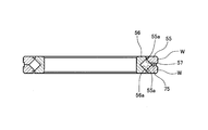
- FIG. 7 is a perspective view including a partial cross section of the slewing bearing
- FIG. 8 is a sectional view of the slewing bearing.
- FIG. 7 and 8 show a slewing bearing incorporating a slewing bearing spacer.
- V-shaped rolling surfaces 55a and 56a are formed on the outer ring 55 and the inner ring 56, respectively, and the rolling surfaces 55a and 56a are formed.
- a plurality of rollers 58a, 58b,... are arranged and stored in the roller rolling path with their inclination directions being alternately intersected.
- a slewing bearing spacer 59 (hereinafter referred to as a spacer) indicated by diagonal lines is interposed between the plurality of rollers 58a, 58b, and holds the rollers 58a, 58b in a predetermined posture.
- the outer ring 55 has a V-shaped rolling surface 55a formed on the inner periphery thereof.
- the opening angle of the V shape is set to approximately 90 degrees.
- the outer ring 55 is composed of a pair of annular workpieces W and is divided into two in the vertical direction for filling the rollers 58 and spacers 59.
- the outer ring 55 is formed with an oil supply hole 75 extending from the outer periphery to the outer ring rolling surface 55a at one place in the circumferential direction.
- the inner ring 56 is fitted on the inner peripheral side of the outer ring 55 so that the outer diameter is substantially matched with the inner diameter of the outer ring 55.
- An inner ring rolling surface 56a is formed on the outer periphery of the inner ring 56 so as to face the outer ring rolling surface 55a.
- the inner ring rolling surface 56a is also V-shaped, and the opening angle is set to approximately 90 degrees.
- the outer ring rolling surface 55a and the inner ring rolling surface 56a constitute a roller rolling path 57 having a substantially square cross section.
- the height of the rollers 58a, 58b,... Is set slightly smaller than their outer diameter.
- the rollers 58 a, 58 b... Adjacent to the left and right of the spacer 59 are classified into an outward roller 58 a and an inward roller 58 b with their axes orthogonal to each other.
- the outward roller 58 a is held by the spacer 59 so that its axis 60 faces the turning center point P ⁇ b> 1 located on the rotation center line P of the outer ring 55 and the inner ring 56.
- the inward roller 58b is also held by the spacer 59 in such a posture that its axis 61 faces the turning center point P2 located on the rotation center line P. Therefore, the axes of the rollers 58a, 58b,... Always keep a right angle with respect to the roller rolling path 57, and the rollers 58a, 58b,.
- the roller rolling path 57 can be formed by the outer ring rolling surface 55a and the inner ring rolling surface 56a by combining the workpieces W heat-treated by the heat treatment apparatus 100 according to the present embodiment.
- a plurality of rollers are arranged and stored in the roller rolling path, and spacers are disposed between the plurality of rollers. And a roller will roll in the roller rolling path.
- An annular workpiece W having a substantially trapezoidal cross-sectional view and heat-treated by the heat treatment apparatus 100 according to the present embodiment is arranged vertically.
- this inner ring is comprised from the substantially rectangular-shaped workpiece
- work W which has the notch of the cross-sectional view substantially U-shape (substantially fallen L-shape) heat-processed by the heat processing apparatus 100 which concerns on a present Example. Become.
- the heating coil 21 and the cooling water discharge unit 23 are provided adjacent to each other in the moving direction of the heat treatment processing unit 20.
- the scope of the present invention is not limited to this. That is, in the direction of the normal use state of the heat treatment apparatus 100, for example, the cooling water discharge portion 23 may be installed on the heating coil 21 and provided side by side.
- the heat treatment apparatus 100 can be applied not only to quenching but also to tempering and annealing.
- tempering the workpiece W for example, the workpiece W can be heated to an appropriate temperature by the heating coil 21 and then cooled by the cooling water discharge portion 23. Even when the workpiece W is annealed, for example, the workpiece W can be gradually cooled by the cooling water discharge portion 23 after being heated to an appropriate temperature by the heating coil 21.
- the pair of swing arms 30 (30a, 30b) swings the pair of heating coils 20 (20a, 20b) relative to the workpiece W, and the pair of heating coils 20 (20a, 20b) starts quenching.
- the workpiece W is fixed on the table 11 and the heat treatment processing is performed by turning the heat treatment processing portion 20 by the swivel arm 30 for explanation.
- the relative positional relationship between the workpiece W and the heat treatment processing unit 20 may be any as long as it can realize the operation example of the heat treatment apparatus described with reference to FIG. 3, for example, while rotating the workpiece W on the table 11.
- the heat treatment apparatus 100 may be operated so that the heat treatment portion 20 is swung by the swivel arm 30.
- the present invention is not limited thereto, and is used for any annular work. be able to.
- a motion guide device is installed on the lower arm 33 so that the swivel arm 30 including the lower arm 33 can be moved in the diametrical direction with respect to the annular workpiece W.
- a spline shaft as a track member of the motion guide device may be incorporated into the lower surface of the upper arm 31 and a spline nut as a movement member of the motion guide device may be incorporated into the vertical arm 32.
- the heat treatment apparatus 10 according to the present embodiment as an example that the present invention can take has been described.
- the present invention and the method of the present invention can take further forms. Therefore, next, a heat treatment apparatus according to the present embodiment having further morphological features will be described with reference to FIGS.
- members that are the same as or similar to those in the above-described embodiment may be denoted by the same reference numerals and description thereof may be omitted.
- FIG. 9 is a schematic diagram illustrating a basic configuration example of the heat treatment apparatus according to the present embodiment.
- FIG. 11 is a schematic diagram for explaining a state in which cooling water is discharged by the first cooling water discharge portion and the second cooling water discharge portion at the end of the heat treatment apparatus according to the present embodiment.
- the heat treatment apparatus 200 includes a table 11 on which an annular workpiece W can be placed, and a pair of heat treatment portions 20 (for heat treatment of the peripheral surface of the workpiece W). 20a, 20b).
- Work W is a processed material that is heat treated.
- the workpiece W in the present embodiment is, for example, an outer ring or an inner ring constituting a slewing bearing, and has a substantially trapezoidal shape or a substantially rectangular shape in cross section.
- the heat treatment is performed on the rolling element rolling surface of the slewing bearing.
- the table 11 can place the workpiece W, and the table 11 according to the present embodiment has a substantially circular shape in plan view. Then, by placing and fixing the workpiece W on the table 11 by a crane 17 which will be described later, it is possible to perform a heat treatment process. And the table 11 is comprised so that it can rotate by making the center of the table 11 into a rotation center axis
- the heat treatment part 20 is for heat-treating the peripheral surface of the work W, and includes a heating coil 21 (21a, 21b) for heating the work W and a first cooling water discharge for cooling the work W. A portion 223 (223a, 223b) and a second cooling water discharge portion 225 (225a, 225b) for cooling the workpiece W are provided.
- the heat treatment part 20 is installed on a revolving arm 30 that can be revolved relative to the table 11 so that heat treatment can be performed on the peripheral surface of the workpiece W.
- the heating coil 21 is configured so as to be disposed to face the peripheral surface of the workpiece W. And the surrounding surface of the workpiece
- work W can be heated now.
- the first cooling water discharge unit 223 is provided in the heating coil 21 and configured to discharge cooling water.
- release part 223 is the 1st cooling water discharge
- a plurality of holes may be formed in the side surface of the slab to release the cooling water.
- release part 225 is comprised so that cooling water can be discharge
- the cooling device 26 for cooling the work W after the heat treatment part 20 is retracted from the burning end portion of the work W includes It is fixedly installed on the table 11 which is the end of baking.
- the cooling device 26 is installed, for example, facing a workpiece W that is an outer ring or an inner ring of a slewing bearing, and a plurality of holes are formed in a surface facing the workpiece W so that cooling water can be discharged. be able to.
- FIG. 10 is a schematic diagram showing a state of the heat treatment apparatus according to the present embodiment
- a partial diagram (a) in the drawing is a schematic diagram showing a state at the start of firing
- a partial diagram (b) in the drawing Is a schematic diagram showing a state between the start and end of firing
- a partial diagram (c) and a partial diagram (d) in the drawing are schematic diagrams showing a state after the firing.
- the shaded portion indicates the portion of the workpiece W that has been heat-treated by the heat treatment apparatus 200 according to the present embodiment.
- the pair of heat treatment parts 20 (20a, 20b) are arranged adjacent to each other.
- the heating coil 21a included in the heat treatment portion 20a heats the workpiece W while the heat treatment portion 20a on the left side of the drawing moves in the upper left direction along the peripheral surface of the workpiece W. And the workpiece
- the first cooling water discharge part 223a discharges the cooling water, the workpiece W is cooled and heat treatment (quenching) is performed.
- the heat treatment part 20b on the right side of the paper moves along the peripheral surface of the workpiece W in the upper right direction on the paper surface, while the heating coil 21b included in the heat treatment part 20b has the workpiece W is heated, and the heated workpiece W is sequentially cooled by the first cooling water discharge portion 223b. More specifically, the heating coil 21b heats the peripheral surface of the workpiece W on the surface facing the heat treatment processing portion 20b while the heat treatment processing portion 20b pivots in the upper right direction on the paper surface, and then the heated workpiece W is heated.
- the first cooling water discharge part 223b discharges the cooling water, the workpiece W is cooled and heat treatment (quenching) is performed.
- the pair of heat treatment parts 20 (20a, 20b) performs heat treatment (quenching) over the entire circumference of the peripheral surface of the workpiece W.
- the heat treatment processing unit 20a on the left side of the drawing is included in the heat treatment processing unit 20a while turning in the upper right direction on the drawing along the peripheral surface of the workpiece W.
- the peripheral surface of the workpiece W is heated by the heating coil 21a, and the heated workpiece W is sequentially cooled by the cooling water discharged from the first cooling water discharge portion 223a that turns.
- the heat treatment processing part 20b on the right side of the paper is heated by heating the peripheral surface of the work W by the heating coil 21b included in the heat treatment processing part 20b while turning in the upper left direction of the paper along the peripheral surface of the work W. Then, the workpiece W is sequentially cooled by the cooling water discharged from the first cooling water discharge portion 223b that subsequently turns.
- the pair of heat treatment parts 20 (20a, 20b) move to positions adjacent to each other as shown in the partial diagram (c) of FIG.
- the heat treatment parts 20 (20a, 20b) are discharged from the first cooling water discharge part 223 (223a, 223b).
- the cooling is performed including the cooling by the cooling water discharged from the second cooling water discharge portion 225 (225a, 225b). More specifically, for example, as shown in FIG. 11, the cooling water discharged from the side surface of the first cooling water discharge portion 223 (223a, 223b) and the heating coil 21 (21a, 21b) are installed at a position overlapping.
- the cooling water discharged from the second cooling water discharge portion 225 (225a, 225b) cools the entire peripheral surface of the workpiece W at the end of firing.
- the pair of heat treatment portions 20 (20a, 20b) are retracted from the end of firing, and the components shown in FIG. As shown in FIG. 4D, the cooling of the workpiece W is further advanced by the cooling device 26 fixedly installed at the end of firing. It should be noted that the retreating of the pair of heat treatment parts 20 (20a, 20b) from the end of firing is a pair of heat treatment parts 20 in a direction opposite to the moving direction of the heat treatment parts 20 (20a, 20b) subjected to the heat treatment. (20a, 20b) may be moved.
- the first cooling is performed. Cooling is not sufficiently performed at the first cooling water discharge portion 223 (223a, 223b) at locations other than the peripheral surface portion of the work W facing the location where the water discharge portion 223 (223a, 223b) is located. . Therefore, in the prior art, a separate cooling device is installed at the end of firing, and cooling water is discharged toward the center of the end of firing.
- the cooling of the peripheral surface of the work W heated by the heating coil 21 (21a, 21b) is cooled by the second cooling water discharge unit 225 (225a, 225b).
- the second cooling water discharge unit 225 225a, 225b
- the moving speed of the pair of heat treatment parts 20 (20a, 20b) is reduced, and the workpiece W heated by the heating coils 21 (21a, 21b) is transferred to the first cooling water discharge part 223. (223a, 223b), the second cooling water discharge section 225 (225a, 225b) and the cooling device 26, the entire region from the start to the end of baking can be quenched sequentially. It became possible to prevent cracking.
- the cracking occurs due to thermal expansion when the workpiece W is quenched, the workpiece W is sequentially quenched from the start to the end of quenching as in the present embodiment.
- the heat treatment is performed over the entire circumference of the peripheral surface of the work W, and an annular work W in which a uniform hardened layer is formed over the entire circumference is obtained. Will be able to.
- the scope of the present invention is not limited to these, and any conditions may be used as long as quenching is performed sequentially from the start of firing to the end of firing and a workpiece W having desired properties is obtained. It can be appropriately adjusted depending on the heating / cooling conditions, the composition of the workpiece W, and the like.
- the heat treatment apparatus 200 according to this embodiment also realizes the heat treatment processing according to the present embodiment with the specific apparatus configuration described with reference to FIGS. 4 to 6, similarly to the above-described embodiment. Can do. Further, for the workpiece W that has been heat-treated by the heat treatment apparatus 200 according to the present embodiment, the outer ring 55 and the inner ring 56 of the slewing bearing described with reference to FIGS. 7 and 8, for example, as in the above-described embodiment. Can be used as
- the heat treatment apparatus 200 according to the present embodiment is configured to include only one pair of the pair of heat treatment parts 20, but the heat treatment apparatus according to the present invention includes a plurality of pairs of the heat treatment parts 20. It is possible.
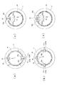
- FIG. 12 is a schematic diagram for illustrating various configuration examples of the heat treatment apparatus according to the present invention.
- each heat treatment part 20 quenches approximately 1/6 of the annular workpiece W. can do. Further, as shown in the partial diagram (b) of FIG. 12, when four pairs of the heat treatment parts 20 are arranged, each heat treatment part 20 quenches approximately 1/8 of the annular workpiece W. can do.
- the quenching time can be shortened compared to the case of using a pair of the heat treatment parts 20 and a heat treatment apparatus with high productivity can be realized. It becomes like this. Further, by arranging a plurality of sets of the pair of heat treatment parts 20, it is possible to prevent the distortion of the workpiece W from being accumulated and to reduce the distortion of the hardened workpiece W.
- the heating coil 21 and the first cooling water discharge unit 223 are provided adjacent to each other in the moving direction of the heat treatment processing unit 20.
- the range is not limited to this. That is, in the direction of the normal use state of the heat treatment apparatus 200, for example, the first cooling water discharge unit 223 may be installed on the heating coil 21 and provided side by side.
- the heat treatment apparatus 200 can be applied not only to quenching but also to tempering and annealing.
- tempering the workpiece W for example, after heating to an appropriate temperature by the heating coil 21, it can be cooled by the first cooling water discharge portion 223 or the second cooling water discharge portion 225.
- the relative positional relationship between the workpiece W and the heat treatment portion 20 may be any as long as it can realize the basic operation example of the heat treatment apparatus described with reference to FIGS. 10 and 11, and the workpiece W on the table 11 is rotated.
- the heat treatment apparatus 200 may be operated so that the heat treatment processing unit 20 is swung by the swivel arm 30.
- the present invention is not limited to this and is used for any annular work. be able to.
- a motion guide device is installed on the lower arm 33 so that the swivel arm 30 including the lower arm 33 can be moved in the diameter direction with respect to the annular workpiece W.
- a spline shaft as a track member of the motion guide device may be incorporated into the lower surface of the upper arm 31 and a spline nut as a movement member of the motion guide device may be incorporated into the vertical arm 32.
Abstract
Description
図4に示すように、本実施例に係る熱処理装置100は、テーブル11などの基礎となるベース13と、テーブル11を回転させるための回転部15と、回転部15に載置されるテーブル11と、テーブル11に対して相対的に旋回移動が可能な一対の旋回アーム30と、一対の旋回アーム30にそれぞれ設置される一対の熱処理加工部20と、を有して構成される。 [Example]
As shown in FIG. 4, the
Claims (8)
- 環状のワークを載置可能なテーブルと、
前記ワークの周面を熱処理加工するための一対の熱処理加工部と、
を備え、
前記一対の熱処理加工部が、前記ワークの周面に沿って互いに反対方向に移動しながら当該ワークに熱処理加工を施すことで、所望の性質を有するワークを得るために用いられる熱処理装置において、
前記テーブルに対して相対的に移動可能な一対の旋回アームが、前記ワークに対して前記一対の熱処理加工部を相対的に揺動することにより、前記ワークの周面を熱処理加工することを特徴とする熱処理装置。 A table on which an annular workpiece can be placed;
A pair of heat treatment parts for heat treating the peripheral surface of the workpiece;
With
In the heat treatment apparatus used for obtaining a workpiece having a desired property by performing a heat treatment on the workpiece while moving the pair of heat treatment portions in opposite directions along the peripheral surface of the workpiece,
A pair of revolving arms movable relative to the table swings the pair of heat treatment parts relative to the work, thereby heat treating the peripheral surface of the work. Heat treatment equipment. - 請求項1に記載の熱処理装置において、
前記一対の熱処理加工部は、
前記ワークの周面に対して対向配置可能な一対の加熱コイルと、
前記加熱コイルに併設されるとともに冷却水を放出するための一対の冷却水放出部と、
を備え、
前記一対の熱処理加工部が揺動するときは、前記一対の加熱コイルが前記一対の冷却水放出部を挟んでいることを特徴とする熱処理装置。 The heat treatment apparatus according to claim 1,
The pair of heat treatment parts are:
A pair of heating coils that can be arranged opposite to the peripheral surface of the workpiece;
A pair of cooling water discharge portions that are provided alongside the heating coil and discharge cooling water;
With
When the pair of heat treatment parts swings, the pair of heating coils sandwich the pair of cooling water discharge parts. - 請求項1又は2に記載の熱処理装置において、
前記一対の熱処理加工部が複数組設置されるととともに前記一対の旋回アームが複数組設置されることを特徴とする熱処理装置。 In the heat treatment apparatus according to claim 1 or 2,
A heat treatment apparatus, wherein a plurality of sets of the pair of heat treatment parts are installed and a plurality of sets of the pair of turning arms are installed. - 環状のワークを載置可能なテーブルと、
前記ワークの周面を熱処理加工するための一対の熱処理加工部と、
を備える熱処理装置を用いて、
前記テーブルに対して相対的に旋回移動が可能な一対の旋回アームが、前記ワークに対して前記一対の熱処理加工部を相対的に揺動して熱処理加工をした後に、前記一対の熱処理加工部が、前記ワークの周面に沿って互いに反対方向に移動しながら当該ワークに熱処理加工を施すことで、前記ワークの周面の全周にわたって熱処理加工が行われることを特徴とする熱処理方法。 A table on which an annular workpiece can be placed;
A pair of heat treatment parts for heat treating the peripheral surface of the workpiece;
Using a heat treatment apparatus comprising
A pair of swivel arms capable of swiveling relative to the table performs a heat treatment by swinging the pair of heat treatment parts relative to the workpiece, and then the pair of heat treatment parts. However, the heat treatment is performed over the entire circumference of the peripheral surface of the workpiece by performing the heat treatment on the workpiece while moving in the opposite directions along the peripheral surface of the workpiece. - 請求項1に記載の熱処理装置において、
前記熱処理加工部が、
前記ワークの周面に対して対向配置可能な加熱コイルと、
前記加熱コイルに併設されるとともに冷却水を放出するための第一冷却水放出部と、
前記加熱コイルと重畳する位置に設置されるとともに冷却水を放出するための第二冷却水放出部と、
を備えることにより、
前記一対の熱処理加工部が前記ワークの周面に沿って互いに反対方向に移動するときには、前記加熱コイルによって加熱された前記ワークの周面を前記第一冷却水放出部から放出される冷却水によって順次冷却し、
前記一対の熱処理加工部が隣り合う位置まで移動したときには、前記加熱コイルによって加熱された前記ワークの周面の冷却を、前記第二冷却水放出部から放出される冷却水を含めて実施することで、前記ワークの周面の全周にわたって熱処理加工が行われることを特徴とする熱処理装置。 The heat treatment apparatus according to claim 1,
The heat treatment part is
A heating coil that can be disposed opposite to the peripheral surface of the workpiece;
A first cooling water discharge part for discharging cooling water, which is attached to the heating coil;
A second cooling water discharge part which is installed at a position overlapping with the heating coil and discharges cooling water;
By providing
When the pair of heat treatment parts move in directions opposite to each other along the peripheral surface of the workpiece, the peripheral surface of the workpiece heated by the heating coil is cooled by the cooling water discharged from the first cooling water discharge unit. Cool sequentially,
When the pair of heat treatment parts move to adjacent positions, cooling of the peripheral surface of the workpiece heated by the heating coil is performed including the cooling water discharged from the second cooling water discharge part. In the heat treatment apparatus, heat treatment is performed over the entire circumference of the peripheral surface of the workpiece. - 請求項5に記載の熱処理装置において、
前記一対の熱処理加工部は、前記テーブルに対して相対的に旋回移動が可能な一対の旋回アームにそれぞれ設置されていることを特徴とする熱処理装置。 The heat treatment apparatus according to claim 5,
The pair of heat treatment parts are respectively installed on a pair of swivel arms that can swivel relative to the table. - 請求項5又は6に記載の熱処理装置において、
前記一対の熱処理加工部が複数組設置されていることを特徴とする熱処理装置。 In the heat treatment apparatus according to claim 5 or 6,
A heat treatment apparatus comprising a plurality of sets of the pair of heat treatment parts. - 環状のワークを載置可能なテーブルと、
前記ワークの周面を熱処理加工するための一対の熱処理加工部と、
前記ワークの周面に対して対向配置可能な加熱コイルと、
前記加熱コイルに併設されるとともに冷却水を放出するための第一冷却水放出部と、
前記加熱コイルと重畳する位置に設置されるとともに冷却水を放出するための第二冷却水放出部と、
を備える熱処理装置を用いて、
前記一対の熱処理加工部が、前記ワークの周面に沿って互いに反対方向に移動しながら当該ワークに熱処理加工を施すことで、所望の性質を有するワークを得る熱処理方法において、
前記一対の熱処理加工部が前記ワークの周面に沿って互いに反対方向に移動するときには、前記加熱コイルによって加熱された前記ワークの周面を前記第一冷却水放出部から放出される冷却水によって順次冷却し、
前記一対の熱処理加工部が隣り合う位置まで移動したときには、前記加熱コイルによって加熱された前記ワークの周面の冷却を、前記第二冷却水放出部から放出される冷却水を含めて実施し、前記ワークの周面の全周にわたって熱処理加工を行うことを特徴とする熱処理方法。 A table on which an annular workpiece can be placed;
A pair of heat treatment parts for heat treating the peripheral surface of the workpiece;
A heating coil that can be disposed opposite to the peripheral surface of the workpiece;
A first cooling water discharge part for discharging cooling water, which is attached to the heating coil;
A second cooling water discharge part which is installed at a position overlapping with the heating coil and discharges cooling water;
Using a heat treatment apparatus comprising
In the heat treatment method for obtaining a workpiece having a desired property by performing a heat treatment on the workpiece while the pair of heat treatment portions move in opposite directions along the peripheral surface of the workpiece,
When the pair of heat treatment parts move in directions opposite to each other along the peripheral surface of the workpiece, the peripheral surface of the workpiece heated by the heating coil is cooled by the cooling water discharged from the first cooling water discharge unit. Cool sequentially,
When the pair of heat treatment parts move to adjacent positions, cooling of the peripheral surface of the workpiece heated by the heating coil is performed including cooling water discharged from the second cooling water discharge part, A heat treatment method comprising performing heat treatment over the entire circumference of the peripheral surface of the workpiece.
Priority Applications (5)
| Application Number | Priority Date | Filing Date | Title |
|---|---|---|---|
| EP15761594.9A EP3119161B1 (en) | 2014-03-11 | 2015-03-11 | Heat-treatment device and heat-treatment method |
| US15/122,313 US10422014B2 (en) | 2014-03-11 | 2015-03-11 | Heat-treatment device and heat-treatment method |
| CN201580009832.2A CN106031301B (en) | 2014-03-11 | 2015-03-11 | Annealing device and heat treatment method |
| ES15761594T ES2784781T3 (en) | 2014-03-11 | 2015-03-11 | Heat treatment device and heat treatment procedure |
| KR1020167024759A KR102207032B1 (en) | 2014-03-11 | 2015-03-11 | Heat-treatment device and heat-treatment method |
Applications Claiming Priority (4)
| Application Number | Priority Date | Filing Date | Title |
|---|---|---|---|
| JP2014-047840 | 2014-03-11 | ||
| JP2014047839A JP5903455B2 (en) | 2014-03-11 | 2014-03-11 | Heat treatment apparatus and heat treatment method |
| JP2014047840A JP6146916B2 (en) | 2014-03-11 | 2014-03-11 | Heat treatment apparatus and heat treatment method |
| JP2014-047839 | 2014-03-11 |
Publications (1)
| Publication Number | Publication Date |
|---|---|
| WO2015136927A1 true WO2015136927A1 (en) | 2015-09-17 |
Family
ID=54071384
Family Applications (1)
| Application Number | Title | Priority Date | Filing Date |
|---|---|---|---|
| PCT/JP2015/001334 WO2015136927A1 (en) | 2014-03-11 | 2015-03-11 | Heat-treatment device and heat-treatment method |
Country Status (7)
| Country | Link |
|---|---|
| US (1) | US10422014B2 (en) |
| EP (1) | EP3119161B1 (en) |
| KR (1) | KR102207032B1 (en) |
| CN (1) | CN106031301B (en) |
| ES (1) | ES2784781T3 (en) |
| TW (1) | TWI639707B (en) |
| WO (1) | WO2015136927A1 (en) |
Cited By (2)
| Publication number | Priority date | Publication date | Assignee | Title |
|---|---|---|---|---|
| CN106636566A (en) * | 2016-12-07 | 2017-05-10 | 苏州欣航微电子有限公司 | Heat treatment device for engraved lines of metal shell of intelligent door lock |
| CN111385932A (en) * | 2018-12-29 | 2020-07-07 | 同济大学 | Electromagnetic induction heating coil and heating device for isothermal biaxial tension test |
Families Citing this family (4)
| Publication number | Priority date | Publication date | Assignee | Title |
|---|---|---|---|---|
| JP1662789S (en) * | 2019-07-16 | 2020-06-29 | ||
| JP2021072456A (en) | 2019-07-16 | 2021-05-06 | 電気興業株式会社 | Cover assembly |
| DE102020122863A1 (en) * | 2020-09-01 | 2022-03-03 | Sms Elotherm Gmbh | Process and device for the inductive hardening of a surface layer |
| CN113278786B (en) * | 2021-04-29 | 2022-11-29 | 恒进感应科技(十堰)股份有限公司 | Heating quenching method and heating quenching device for surface induction of annular workpiece |
Citations (4)
| Publication number | Priority date | Publication date | Assignee | Title |
|---|---|---|---|---|
| JPH06200326A (en) * | 1992-12-28 | 1994-07-19 | Ntn Corp | Method for hardening bearing ring |
| JP2003342632A (en) * | 2002-05-28 | 2003-12-03 | High Frequency Heattreat Co Ltd | Method and device for induction hardening pin shaft of crank shaft |
| JP2010222672A (en) * | 2009-03-25 | 2010-10-07 | Denki Kogyo Co Ltd | High frequency-induction hardening apparatus for large-size material |
| JP2012219311A (en) * | 2011-04-07 | 2012-11-12 | Neturen Co Ltd | Induction heating apparatus and induction heating method |
Family Cites Families (11)
| Publication number | Priority date | Publication date | Assignee | Title |
|---|---|---|---|---|
| JPS515258A (en) * | 1974-07-03 | 1976-01-16 | Hitachi Cable | EKIATSUOSHI DASHISOCHI |
| JP4097417B2 (en) * | 2001-10-26 | 2008-06-11 | 株式会社ルネサステクノロジ | Semiconductor device |
| DE102005006701B3 (en) * | 2005-02-15 | 2006-03-30 | Rothe Erde Gmbh | Production of bearing ring for large rolling bearing comprises arranging inductors over common zone of annular track to be hardened, heating the opposite-lying edge layer to the hardening temperature and further processing |
| DE102006003014B3 (en) | 2006-01-23 | 2007-10-18 | Sms Elotherm Gmbh | Method for hardening a workpiece describing a closed curve |
| DE102008033735A1 (en) | 2008-07-18 | 2010-02-18 | Rothe Erde Gmbh | Method for hardening at least one raceway of a bearing race for a slewing bearing |
| US20100243643A1 (en) * | 2009-03-30 | 2010-09-30 | Cesano Mariolino | Device and method for performing a localized induction hardening treatment on mechanical components, specifically thrust blocks for large-sized rolling bearings |
| RU2520569C2 (en) * | 2009-07-30 | 2014-06-27 | Нетурен Ко., Лтд. | Device for inductive tempering, inductive tempering process, inductor to this end, device for heat treatment and heat treatment process |
| DE102009053197A1 (en) * | 2009-11-06 | 2011-05-12 | Imo Holding Gmbh | Method and device for inductive hardening of large annular workpieces |
| IT1398579B1 (en) * | 2010-03-05 | 2013-03-01 | Saet Spa | METHOD AND DEVICE FOR TEMPERING WITH LOCALIZED INDUCTION OF CIRCULAR COMPONENTS OF LARGE SIZE, IN PARTICULAR RALLE FOR ROLLING BEARINGS |
| WO2011130387A2 (en) | 2010-04-13 | 2011-10-20 | Inductoheat, Inc. | Induction heat treatment of an annular workpiece |
| US10057945B2 (en) | 2011-04-07 | 2018-08-21 | Neturen Co., Ltd. | Induction heating device, induction heating equipment, induction heating method, and heat treatment method |
-
2015
- 2015-03-11 EP EP15761594.9A patent/EP3119161B1/en not_active Revoked
- 2015-03-11 WO PCT/JP2015/001334 patent/WO2015136927A1/en active Application Filing
- 2015-03-11 US US15/122,313 patent/US10422014B2/en active Active
- 2015-03-11 CN CN201580009832.2A patent/CN106031301B/en active Active
- 2015-03-11 ES ES15761594T patent/ES2784781T3/en active Active
- 2015-03-11 TW TW104107862A patent/TWI639707B/en active
- 2015-03-11 KR KR1020167024759A patent/KR102207032B1/en active IP Right Grant
Patent Citations (4)
| Publication number | Priority date | Publication date | Assignee | Title |
|---|---|---|---|---|
| JPH06200326A (en) * | 1992-12-28 | 1994-07-19 | Ntn Corp | Method for hardening bearing ring |
| JP2003342632A (en) * | 2002-05-28 | 2003-12-03 | High Frequency Heattreat Co Ltd | Method and device for induction hardening pin shaft of crank shaft |
| JP2010222672A (en) * | 2009-03-25 | 2010-10-07 | Denki Kogyo Co Ltd | High frequency-induction hardening apparatus for large-size material |
| JP2012219311A (en) * | 2011-04-07 | 2012-11-12 | Neturen Co Ltd | Induction heating apparatus and induction heating method |
Non-Patent Citations (1)
| Title |
|---|
| See also references of EP3119161A4 * |
Cited By (2)
| Publication number | Priority date | Publication date | Assignee | Title |
|---|---|---|---|---|
| CN106636566A (en) * | 2016-12-07 | 2017-05-10 | 苏州欣航微电子有限公司 | Heat treatment device for engraved lines of metal shell of intelligent door lock |
| CN111385932A (en) * | 2018-12-29 | 2020-07-07 | 同济大学 | Electromagnetic induction heating coil and heating device for isothermal biaxial tension test |
Also Published As
| Publication number | Publication date |
|---|---|
| EP3119161A1 (en) | 2017-01-18 |
| EP3119161A4 (en) | 2017-03-01 |
| TWI639707B (en) | 2018-11-01 |
| US20160369366A1 (en) | 2016-12-22 |
| KR20160132837A (en) | 2016-11-21 |
| CN106031301B (en) | 2019-12-03 |
| EP3119161B1 (en) | 2020-03-11 |
| KR102207032B1 (en) | 2021-01-22 |
| CN106031301A (en) | 2016-10-12 |
| TW201544600A (en) | 2015-12-01 |
| US10422014B2 (en) | 2019-09-24 |
| ES2784781T3 (en) | 2020-09-30 |
Similar Documents
| Publication | Publication Date | Title |
|---|---|---|
| WO2015136927A1 (en) | Heat-treatment device and heat-treatment method | |
| RU2448168C2 (en) | Method and device for hardening of part described with closed curve | |
| JP4674932B2 (en) | Crawler belt bush, manufacturing method and manufacturing apparatus thereof | |
| JP2010222672A (en) | High frequency-induction hardening apparatus for large-size material | |
| JP2012144768A (en) | Method of quenching crankshaft and crankshaft | |
| JP5553440B2 (en) | Heat treatment method and heat treatment apparatus | |
| JP2004052013A (en) | High frequency induction heating coil body | |
| CN109439852A (en) | A kind of drive shaft quenching unit and process for quenching with the angle R | |
| JP5557235B2 (en) | Heat treatment method for ring-shaped member, method for manufacturing ring-shaped member | |
| JP5179203B2 (en) | Heat treatment equipment for cylindrical metal members | |
| JP6146916B2 (en) | Heat treatment apparatus and heat treatment method | |
| JP5455031B2 (en) | Manufacturing method of bearing ring and manufacturing method of rolling bearing | |
| JP5903455B2 (en) | Heat treatment apparatus and heat treatment method | |
| JP6671830B2 (en) | Heat treatment equipment | |
| JP6229226B2 (en) | Heat treatment method | |
| JP2013216959A (en) | Thermal treatment equipment for ring-shaped member | |
| JP6403960B2 (en) | Heat treatment equipment | |
| KR20140089667A (en) | High freguency induction heat teratment for inner and outer race of ring gear | |
| JP5765684B2 (en) | Heat treatment method | |
| JP2016089183A (en) | Heat treatment method for workpiece | |
| JP6009708B2 (en) | Method for surface hardening of steel parts | |
| JP5527154B2 (en) | Induction hardening equipment for shaft-shaped members | |
| US20230220512A1 (en) | Induction hardening system and induction hardening method | |
| WO2024057405A1 (en) | Traverse hardening method and traverse hardening device | |
| JP2017036507A (en) | Method of performing surface hardening to steel component |
Legal Events
| Date | Code | Title | Description |
|---|---|---|---|
| 121 | Ep: the epo has been informed by wipo that ep was designated in this application |
Ref document number: 15761594 Country of ref document: EP Kind code of ref document: A1 |
|
| WWE | Wipo information: entry into national phase |
Ref document number: 15122313 Country of ref document: US |
|
| REEP | Request for entry into the european phase |
Ref document number: 2015761594 Country of ref document: EP |
|
| WWE | Wipo information: entry into national phase |
Ref document number: 2015761594 Country of ref document: EP |
|
| ENP | Entry into the national phase |
Ref document number: 20167024759 Country of ref document: KR Kind code of ref document: A |
|
| NENP | Non-entry into the national phase |
Ref country code: DE |