WO2015133406A1 - シール構造、及びそれを用いた歯車ポンプ又はモータ - Google Patents
シール構造、及びそれを用いた歯車ポンプ又はモータ Download PDFInfo
- Publication number
- WO2015133406A1 WO2015133406A1 PCT/JP2015/055942 JP2015055942W WO2015133406A1 WO 2015133406 A1 WO2015133406 A1 WO 2015133406A1 JP 2015055942 W JP2015055942 W JP 2015055942W WO 2015133406 A1 WO2015133406 A1 WO 2015133406A1
- Authority
- WO
- WIPO (PCT)
- Prior art keywords
- cover
- outside
- gear
- gasket
- groove
- Prior art date
- Legal status (The legal status is an assumption and is not a legal conclusion. Google has not performed a legal analysis and makes no representation as to the accuracy of the status listed.)
- Ceased
Links
Images







Classifications
-
- F—MECHANICAL ENGINEERING; LIGHTING; HEATING; WEAPONS; BLASTING
- F04—POSITIVE - DISPLACEMENT MACHINES FOR LIQUIDS; PUMPS FOR LIQUIDS OR ELASTIC FLUIDS
- F04C—ROTARY-PISTON, OR OSCILLATING-PISTON, POSITIVE-DISPLACEMENT MACHINES FOR LIQUIDS; ROTARY-PISTON, OR OSCILLATING-PISTON, POSITIVE-DISPLACEMENT PUMPS
- F04C2/00—Rotary-piston machines or pumps
- F04C2/08—Rotary-piston machines or pumps of intermeshing-engagement type, i.e. with engagement of co-operating members similar to that of toothed gearing
- F04C2/12—Rotary-piston machines or pumps of intermeshing-engagement type, i.e. with engagement of co-operating members similar to that of toothed gearing of other than internal-axis type
- F04C2/14—Rotary-piston machines or pumps of intermeshing-engagement type, i.e. with engagement of co-operating members similar to that of toothed gearing of other than internal-axis type with toothed rotary pistons
- F04C2/18—Rotary-piston machines or pumps of intermeshing-engagement type, i.e. with engagement of co-operating members similar to that of toothed gearing of other than internal-axis type with toothed rotary pistons with similar tooth forms
-
- F—MECHANICAL ENGINEERING; LIGHTING; HEATING; WEAPONS; BLASTING
- F04—POSITIVE - DISPLACEMENT MACHINES FOR LIQUIDS; PUMPS FOR LIQUIDS OR ELASTIC FLUIDS
- F04C—ROTARY-PISTON, OR OSCILLATING-PISTON, POSITIVE-DISPLACEMENT MACHINES FOR LIQUIDS; ROTARY-PISTON, OR OSCILLATING-PISTON, POSITIVE-DISPLACEMENT PUMPS
- F04C15/00—Component parts, details or accessories of machines, pumps or pumping installations, not provided for in groups F04C2/00 - F04C14/00
- F04C15/0003—Sealing arrangements in rotary-piston machines or pumps
- F04C15/0007—Radial sealings for working fluid
- F04C15/0015—Radial sealings for working fluid of resilient material
-
- F—MECHANICAL ENGINEERING; LIGHTING; HEATING; WEAPONS; BLASTING
- F16—ENGINEERING ELEMENTS AND UNITS; GENERAL MEASURES FOR PRODUCING AND MAINTAINING EFFECTIVE FUNCTIONING OF MACHINES OR INSTALLATIONS; THERMAL INSULATION IN GENERAL
- F16J—PISTONS; CYLINDERS; SEALINGS
- F16J15/00—Sealings
- F16J15/002—Sealings comprising at least two sealings in succession
- F16J15/004—Sealings comprising at least two sealings in succession forming of recuperation chamber for the leaking fluid
-
- F—MECHANICAL ENGINEERING; LIGHTING; HEATING; WEAPONS; BLASTING
- F16—ENGINEERING ELEMENTS AND UNITS; GENERAL MEASURES FOR PRODUCING AND MAINTAINING EFFECTIVE FUNCTIONING OF MACHINES OR INSTALLATIONS; THERMAL INSULATION IN GENERAL
- F16J—PISTONS; CYLINDERS; SEALINGS
- F16J15/00—Sealings
- F16J15/02—Sealings between relatively-stationary surfaces
- F16J15/06—Sealings between relatively-stationary surfaces with solid packing compressed between sealing surfaces
- F16J15/062—Sealings between relatively-stationary surfaces with solid packing compressed between sealing surfaces characterised by the geometry of the seat
-
- F—MECHANICAL ENGINEERING; LIGHTING; HEATING; WEAPONS; BLASTING
- F04—POSITIVE - DISPLACEMENT MACHINES FOR LIQUIDS; PUMPS FOR LIQUIDS OR ELASTIC FLUIDS
- F04C—ROTARY-PISTON, OR OSCILLATING-PISTON, POSITIVE-DISPLACEMENT MACHINES FOR LIQUIDS; ROTARY-PISTON, OR OSCILLATING-PISTON, POSITIVE-DISPLACEMENT PUMPS
- F04C2240/00—Components
- F04C2240/30—Casings or housings
Definitions
- the present invention is used in a hydraulic / pneumatic device, and has a seal structure for a part that joins between joint surfaces of first and second parts having a path through which a fluid such as hydraulic fluid flows, and such a seal structure.
- the present invention relates to a gear pump or a motor adopting the above.
- a seal groove for arranging a seal member is formed in one of the first and second parts to be joined, and the seal member is arranged inside the seal groove. I am doing so.
- the seal member protrudes outside the seal groove during the process of joining the first and second parts, or there is a defect in the seal member.
- a gap is generated between the mating surfaces of the components, causing a problem that fluid leaks from the seal member to the outside air side.
- the present invention focuses on the above points and aims to make it possible to detect the occurrence of a gap in the mating surfaces of the components in a short time.
- the seal structure for parts according to the present invention has a configuration as described below.
- the component seal structure according to the present invention is a member seal structure that uses an annular seal member provided between the joint surfaces of the first component and the second component facing each other.
- a groove is provided on at least one of the two parts and on the outside air side of the seal member, and the groove is an open groove communicating with the outside of the first and second parts.
- the open groove is located on the outside air side of the seal member, and an annular portion, and the annular portion And an opening that communicates with the outside of the first and second parts, and is partitioned into a plurality of compartments, and the annular portion is independent and intermittently arranged in each compartment It is composed of a plurality of partial annular portions that are made to communicate with each other through the openings.
- each compartment communicates with the outside only by the opening, and the hydraulic fluid leaks from the opening belonging to the compartment closest to the location where the gap is generated, so that fluid leakage is detected. This is because it can be determined that the gap is generated in the section corresponding to the opened opening.
- a body that is a first part having a gear housing chamber therein and a cover that is a second part that closes the gear housing chamber of the body are joined.
- a circumscribed gear pair housed and held in a gear housing chamber of the casing and meshed with each other, and the above-described joint portion between the body and the cover of the casing.
- Examples thereof include a gear pump or a motor that employs the seal structure described in 1 or 2.
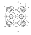
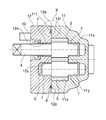
- FIG. 3 is a sectional view taken along line AA in FIG. 2.
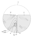
- BB sectional drawing in FIG. The enlarged view of the X section in FIG.
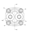
- the enlarged view of the Y section in FIG. The side view which shows the gear pump which concerns on 2nd embodiment of this invention.
- CC sectional drawing in FIG. DD sectional drawing in FIG. The enlarged view of the XX part in FIG.
- the enlarged view of the Z section in FIG. The figure which shows the junctional part of the body and cover in the conventional gear pump.
- the gear pump mainly includes a body 11 that is a first part having a gear housing chamber 11a therein and a gear housing chamber 11a that closes the gear housing chamber 11a. 2, a casing 1 formed by joining a cover 12, a circumscribed gear pair housed and held in a gear housing chamber 11 a of the casing 1, that is, a drive gear 2 and a driven gear 3, and the drive A bush 7 disposed between the bearing holes 11x, 11y, 12x, 12y and the shafts 4 and 5 for housing the drive shaft 4 and the driven shaft 5 for supporting the gear 2 and the driven gear 3, respectively; A gasket 8 is provided as a seal member located between the body 11 and the cover 12.
- the drive gear 2 and the driven gear 3 are well-known ones having a plurality of tooth bodies provided at predetermined intervals along the outer peripheral surface as shown in FIG.
- the drive shaft 4 is integrally extended from the center of the drive gear 2 in the rotational axis direction
- the driven shaft 5 is integrally extended from the driven gear 3 in the rotational axis direction.
- the drive gear 2 and the drive shaft 4 may be configured separately, and the driven gear 3 and the driven shaft 5 may be configured separately.
- the casing 1 is formed by joining a body 11 and a cover 12 with a bolt 10 which is a fastening tool.
- the body 11 includes a gear housing chamber 11a for housing the drive gear 2 and the driven gear 3, a high-pressure side port 11b communicating with the gear housing chamber 11a, and a gear housing.
- a low-pressure side port 11c communicating with the chamber 11a and shaft holes 11x and 11y for inserting the drive shaft 4 and the driven shaft 5 respectively are formed.
- the bush 7 is disposed between the inner surface of the shaft hole 11 x and the drive shaft 4 and between the inner surface of the shaft hole 11 y and the driven shaft 5.
- the front surface 11 f of the body 11 faces the cover 12. In other words, the front surface 11 f of the body 11 is a seal surface (joint surface) with the cover 12.
- the cover 12 is provided with shaft holes 12x and 12y for inserting the drive shaft 2 and the driven shaft 3 respectively.
- the bush 7 is disposed between the inner surface of the shaft hole 12 x and the drive shaft 4 and between the inner surface of the shaft hole 12 y and the driven shaft 5.
- the rear surface 12r of the cover 12 faces the body 11, in other words, the rear surface 12r is a sealing surface (joint surface) with the body 11, and the gasket 8 is disposed on the rear surface 12r.
- the gasket groove 12z is provided.
- the gasket groove 12z has an annular shape, and is entirely disposed on the outside air side of the portion facing the gear housing chamber 11a.
- an open groove 12a that communicates with the outside of the gear pump is provided further on the outside air side than the gasket groove 12z on the rear surface 12r of the cover 12.
- the open groove 12a includes an annular portion 12a1 that is located on the outside air side of the gasket groove 12z and has an annular shape, and two openings 12a2 that communicate the annular portion 12a1 and the outside.
- the gasket 8 protrudes from the gasket groove 12z.
- a gap is generated between the front surface 11f of the body 11 and the rear surface 12r of the cover 12 at the location where the gasket or the gasket is missing.
- the body a11 and the cover a12 are joined with the gasket a8 protruding from the gasket groove a12z, or the gasket a8 has a defective portion.
- the gear pump is operated in the presence of the hydraulic fluid, as described above, the hydraulic fluid that has leaked from the gear housing chamber (not shown) and reached the gasket groove a12z further flows between the front surface a12f of the body a11 and the rear surface a12r of the cover a12 Is leaked to the outside of the gear pump only after a long distance from the gasket groove a12z to the outside of the gear pump.
- the hydraulic fluid leaks from the opening 12a2 only when the hydraulic fluid passes through a long distance from the gasket groove 12z to the outside of the gear pump.
- the joining structure of the body 11 and the cover 12 when the working fluid flows through a short distance from the gasket groove 12z to the open groove 12a, leakage of the working fluid from the opening 12a2 is visually recognized. Therefore, by adopting the configuration of the present embodiment, it is possible to confirm the leakage of the hydraulic fluid due to the attachment failure or missing of the gasket 8 in a shorter time. That is, it is possible to easily find defective attachment or missing gasket 8 during inspection at the time of shipment with a limited time.
- the open groove 12a communicates with the outside only through the opening 12a2 at a finite location, the hydraulic fluid leaks only from the opening 12a2, and when the fluid leakage is discovered, the opening 12a2 Just pay attention. Therefore, it is possible to detect a defective attachment or a defect of the gasket 8 more efficiently.
- annular portion of the open groove is not limited to one that is continuous over the entire circumference like the one according to the first embodiment described above, for example, as according to the second embodiment of the present invention as described below, It may be provided with a plurality of partial annular portions arranged annularly intermittently.
- the second embodiment will be described below with reference to FIGS.
- symbol are attached
- the gear pump according to the present embodiment also mainly includes a body 11 that is a first part having a gear housing chamber 11a therein and a gear housing chamber 11a of the body 11 as shown in FIGS. 2, a casing 1 formed by joining a cover 12, a circumscribed gear pair housed and held in a gear housing chamber 11 a of the casing 1, that is, a drive gear 2 and a driven gear 3, and the drive A bush 7 disposed between the bearing holes 11x, 11y, 12x, 12y and the shafts 4 and 5 for housing the drive shaft 4 and the driven shaft 5 for supporting the gear 2 and the driven gear 3, respectively;
- a gasket 8 is provided as a seal member located between the body 11 and the cover 12.
- the drive gear 2 and the driven gear 3 are well-known ones having a plurality of tooth bodies provided at predetermined intervals along the outer peripheral surface as shown in FIG.
- the drive shaft 4 is integrally extended from the center of the drive gear 2 in the rotational axis direction
- the driven shaft 5 is integrally extended from the driven gear 3 in the rotational axis direction.
- the drive gear 2 and the drive shaft 4 may be configured separately, and the driven gear 3 and the driven shaft 5 may be configured separately.
- the casing 1 is formed by joining a body 11 and a cover 12 with a bolt 10 which is a fastening tool.
- the body 11 has a gear housing chamber 11a for housing the drive gear 2 and the driven gear 3, a high-pressure side port 11b communicating with the gear housing chamber 11a, and a gear housing.
- a low-pressure side port 11c communicating with the chamber 11a and shaft holes 11x and 11y for inserting the drive shaft 4 and the driven shaft 5 respectively are formed.
- the bush 7 is disposed between the inner surface of the shaft hole 11 x and the drive shaft 4 and between the inner surface of the shaft hole 11 y and the driven shaft 5.
- the front surface 11 f of the body 11 faces the cover 12. In other words, the front surface 11 f of the body 11 is a seal surface (joint surface) with the cover 12.
- the cover 12 is provided with shaft holes 12x and 12y through which the drive shaft 2 and the driven shaft 3 are inserted, respectively.
- the bush 7 is disposed between the inner surface of the shaft hole 12 x and the drive shaft 4 and between the inner surface of the shaft hole 12 y and the driven shaft 5.
- the rear surface 12r of the cover 12 faces the body 11, in other words, the rear surface 12r is a sealing surface (joint surface) with the body 11, and the gasket 8 is disposed on the rear surface 12r.
- the gasket groove 12z is provided.
- the gasket groove 12z has an annular shape, and is entirely disposed on the outside air side of the portion facing the gear housing chamber 11a.
- an open groove 12a communicating with the outside of the gear pump is provided further on the outside air side than the gasket groove 12z on the rear surface 12r of the cover 12. .
- the open groove 12a is also provided with an annular portion 12a1 that is located on the outside air side of the gasket groove 12z and has an annular shape, and an opening portion 12a2 that communicates the annular portion 12a1 with the outside.
- the open groove 12a is divided into a plurality of sections 12aA.
- the annular portion 12a1 includes a plurality of partial annular portions 12a3 that are independently and intermittently arranged annularly for each section 12aA, and a blocking portion 12a4 that blocks between the partial annular portions 12a2.
- Each of the partial annular portions 12a3 communicates with the outside through one opening 12a2.
- each partial annular portion 12 a 3 is provided outside the gasket groove 12 z in other portions except for the vicinity of the bolt hole 12 b for inserting the bolt 10. .
- the gasket 8 protrudes from the gasket groove 12z.
- a gap is generated between the front surface 11f of the body 11 and the rear surface 12r of the cover 12 at the location where the gasket or the gasket is missing.
- the open groove 12a includes an annular portion 12a1 that is positioned on the outside air side of the gasket 8 and has an annular shape, and an opening portion 12a2 that communicates the annular portion 12a1 and the outside, and is divided into a plurality of sections 12aA.
- the annular portion 12a1 is composed of a plurality of partial annular portions 12a3 that are independent of each section 12aA and are intermittently annularly arranged.
- the partial annular portions 12a3 communicate with the outside through the openings 12a2, respectively. Therefore, the following effects can be obtained.
- the partial annular portion 12a3 is not provided in the vicinity of the bolt hole 12b for inserting the bolt 10 that connects the body 11 and the cover 12, the following is provided when the partial annular portion 12a3 is provided in the vicinity of the bolt hole 12b. It is possible to prevent the occurrence of problems described in (1).
- the cover 12 becomes thin at the corresponding portion and the strength is reduced, and the bolt hole 12b is sufficiently provided from the partial annular portion 12a3 to prevent such strength reduction. It is possible to prevent both the problem that the cover 12 and the body 11 are increased in size when they are provided in spaced apart locations.
- the gear housing chamber of the body is opened only forward, and the front of the gear housing chamber is closed by a cover.
- the joint of the body and the front cover and the joint of the body and the rear cover are A seal structure may be adopted.
- the seal structure of the present invention may be adopted at the joint portion with the body cover. .
- the present invention may be applied not only to the joint between the body of the gear pump and the cover, but also to the overall seal structure between two members constituting a device having a path for flowing liquid or gas inside. .
- an open groove is provided only in one of the first component and the second component
- an open groove is provided at a position where the seal surfaces (joint surfaces) of these first and second components face each other. You may employ
- the partial annular portions forming the annular portion are arranged so as not to overlap each other in the radial direction.
- the partial annular portions are independent from each other via the blocking portion. If it is, you may employ
- one opening communicates with each of the partial annular portions, and the partial annular portions communicate with the outside through the openings.
Landscapes
- Engineering & Computer Science (AREA)
- General Engineering & Computer Science (AREA)
- Mechanical Engineering (AREA)
- Physics & Mathematics (AREA)
- Geometry (AREA)
- Details And Applications Of Rotary Liquid Pumps (AREA)
- Rotary Pumps (AREA)
- Gasket Seals (AREA)
Abstract
本発明のシール構造は、第1の部品と第2の部品とが互いに向かい合う接合面間に設けた環状のシール部材を利用する部材のシール構造において、部品同士の合わせ面に隙間が生じていることを短時間の運転で検出可能にすべく、第1の部品であるボディ(11)と第2の部品であるカバー(12)とが互いに向かい合う接合面(11f)、(12r)間に設けた環状のシール部材であるガスケット(8)を利用する部材のシール構造において、(ボディ(11)又は)カバー(12)(の少なくとも一方)におけるガスケット(8)の外気側に、ボディ(11)及びカバー(12)の外部に連通している開放溝(12a)を設ける構成を採用するものである。
Description
本発明は、油空圧機器に用いられ、内部に作動液等の流体が流通する経路を有する第1及び第2の部品の接合面間を接合する部品のシール構造、及びこのようなシール構造を採用した歯車ポンプ又はモータに関する。
歯車ポンプのボディとカバーとの間など、内部に作動液等の流体が流通する経路を有する部品同士を接合するにあたっては、従来より、流体が外部に漏出することを防ぐべく、部品同士が向かい合う接合面間にガスケット等の環状をなすシール部材を配することが行われてきている(例えば、特許文献1を参照)。
ところで、このような部品のシール構造では、接合対象である第1及び第2の部品のうち一方にシール部材を配するためのシール溝を形成し、このシール溝の内部にシール部材を配するようにしている。しかし、第1及び第2の部品を接合する工程中にシール溝の外部にシール部材がはみ出した状態のままこれら第1及び第2の部品が接合されると、あるいはシール部材に欠損箇所が存在すると、部品同士の合わせ面に隙間が生じ、シール部材から外気側に流体が漏出する不具合が発生する。
ところが、従来のシール構造においては、シール溝と第1及び第2の部品の外部との距離が長く、流体がシール溝から部品の外部に達するまで長い時間を要する。そのため、時間が限られた出荷時の検査中に前段で述べた不具合を発見することが困難であった。
本発明は以上の点に着目し、部品同士の合わせ面に隙間が生じていることを短時間の運転で検出可能にすることを目的とする。
以上の課題を解決すべく、本発明に係る部品のシール構造は、以下に述べるような構成を有する。すなわち本発明に係る部品のシール構造は、第1の部品と第2の部品とが互いに向かい合う接合面間に設けた環状のシール部材を利用する部材のシール構造であって、前記第1又は第2の部品の少なくとも一方かつシール部材の外気側に溝が設けられ、この溝が第1及び第2の部品の外部に連通している開放溝である構成を有する。
このようなものであれば、部品同士の合わせ面に隙間が生じている場合、流体はこの隙間から前記開放溝に達し、この開放溝が外部に連通している箇所から流体が漏出するが、シール部材と前記開放溝との間の距離は、従来のシール構造におけるシール部材と部品の外部との間の距離よりも短いので、前記隙間から漏れた流体が外部に導かれるまでの時間も従来よりも短くなる。従って、時間が限られた出荷時の検査中であってもその間に流体が漏出する不具合を発見することが容易となる。
流体の漏出をさらに容易に発見できるようにするための構成として、前記開放溝と前記第1及び第2の部品の外部とを有限箇所の開口により連通させているものが挙げられる。このようなものであれば、流体が外部に漏出する箇所は有限箇所の開口箇所のうちいずれかのみであるので、開口箇所にのみ着目すればよいからである。
さらに、部品同士の合わせ面に隙間が生じている箇所を容易に検知できるようにするための構成として、前記開放溝が、シール部材の外気側に位置し環状をなす環状部と、この環状部と前記第1及び第2の部品の外部とを連通する開口部とを備え、複数の区画に区切られたものであり、前記環状部が、前記各区画ごとに独立し、間欠的に環状配置された複数の部分環状部からなり、これら部分環状部をそれぞれ前記開口部を介して外部に連通させているものが挙げられる。このようなものであれば、各区画が開口部のみで外部に連通しており、前記隙間が生じている箇所に最も近い区画に属する開口部から作動液が漏出するので、流体の漏出が検知された開口部に対応する区画で前記隙間が生じているものと判定できるからである。
本発明による効果を好適に得ることができる利用形態の一例として、歯車収納室を内部に有する第1の部品であるボディ及びこのボディの歯車収納室を閉塞する第2の部品であるカバーを接合してなるケーシングと、このケーシングの歯車収納室内に収納保持され互いに噛み合わせてなる外接歯車対とを有し、前記ケーシングの前記ボディと前記カバーとの間の接合部位に上述したような請求項1又は2記載のシール構造を採用している歯車ポンプ又はモータが挙げられる。
本発明によれば、部品同士の合わせ面に隙間が生じていることを短時間の運転で検出可能にすることができる。
本発明の第一実施形態を、図1~図6を参照しつつ以下に述べる。
本実施形態に係る歯車ポンプは、主として、図1~図4に示すように、歯車収納室11aを内部に有する第1の部品であるボディ11及びこのボディ11の歯車収納室11aを閉塞する第2の部品であるカバー12を接合してなるケーシング1と、このケーシング1の歯車収納室11a内に収納保持され互いに噛み合わせてなる外接歯車対、すなわち駆動歯車2及び従動歯車3と、前記駆動歯車2及び従動歯車3を支持する駆動軸4及び従動軸5をそれぞれ収納するための軸受孔11x、11y,12x、12yと前記軸4、5との間に配設されるブッシュ7と、前記ボディ11と前記カバー12との間に位置するシール部材であるガスケット8とを具備する。
駆動歯車2及び従動歯車3は、図3に示すように、複数の歯体を外周面に沿って所定間隔で設けた周知のものである。なお、本実施形態では、前記駆動歯車2の中心から駆動軸4を回転軸方向に一体に延伸させて設けているとともに、従動歯車3から従動軸5を回転軸方向に一体に延伸させて設けているが、駆動歯車2と駆動軸4とを別体に構成してもよく、また、従動歯車3と従動軸5とを別体に構成してもよい。
前記ケーシング1は、止着具であるボルト10によりボディ11とカバー12とを接合させてなるものである。
ボディ11には、図3に示すように、前記駆動歯車2及び前記従動歯車3を収納するための前記歯車収納室11aと、この歯車収納室11aに連通する高圧側ポート11bと、同じく歯車収納室11aに連通する低圧側ポート11cと、駆動軸4及び従動軸5をそれぞれ挿し通すための軸穴11x、11yとを形成している。前述したように、軸穴11xの内面と駆動軸4との間、及び軸穴11yの内面と従動軸5との間には、ブッシュ7を配している。そして、このボディ11は、前面11fがカバー12に対向している。換言すれば、ボディ11の前面11fがカバー12とのシール面(接合面)である。
カバー12には、図3及び図4に示すように、駆動軸2及び従動軸3をそれぞれ挿し通すための軸穴12x、12yを設けている。前述したように、軸穴12xの内面と駆動軸4との間、及び軸穴12yの内面と従動軸5との間には、ブッシュ7を配している。さらに、このカバー12は、後面12rがボディ11に対向しており、換言すれば後面12rがボディ11とのシール面(接合面)であり、この後面12rに前記ガスケット8を内部に配するためのガスケット溝12zを設けている。このガスケット溝12zは環状のものであり、全体が前記歯車収納室11aと向かい合う部位よりも外気側に配されている。
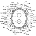
その上で本実施形態では、図3~図6に示すように、前記カバー12の後面12rにおける前記ガスケット溝12zよりもさらに外気側に、歯車ポンプの外部に連通する開放溝12aを設けている。この開放溝12aは、前記ガスケット溝12zの外気側に位置し環状をなす環状部12a1と、この環状部12a1と外部とを連通する2箇所の開口部12a2とを備えている。
ここで、前記ガスケット8がガスケット溝12zからはみ出た状態のままボディ11とカバー12とが接合された場合、あるいはガスケット8に欠損箇所が存在する場合には、ガスケット8がガスケット溝12zからはみ出た箇所あるいはガスケットの欠損箇所においてボディ11の前面11fとカバー12の後面12rとの間に隙間が生じる。このような状態で歯車ポンプを運転すると、歯車収納室11aから漏出してガスケット溝12zに達した作動液は、さらにボディ11とカバー12との隙間、より正確にはボディ11の前面11fとカバー12の後面12rとの間の隙間を流通し開放溝12aに達する。開放溝12aに達した作動液は、開口部12a2から歯車ポンプの外側に漏出する。
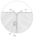
これに対して、従来の構成の歯車ポンプでは、図14に示すように、ガスケットa8がガスケット溝a12zからはみ出た状態のままボディa11とカバーa12とが接合された状態、あるいはガスケットa8に欠損箇所が存在する状態で歯車ポンプを運転すると、前述したように、図示しない歯車収納室から漏出してガスケット溝a12zに達した作動液は、さらにボディa11の前面a12fとカバーa12の後面a12rとの隙間をガスケット溝a12zから歯車ポンプの外部までの長い距離を流通してはじめて歯車ポンプの外側に漏出する。
すなわち、従来の構成の歯車ポンプでは作動液がガスケット溝12zから歯車ポンプの外部までの長い距離を通過してはじめて開口部12a2からの作動液の漏出が視認されるのに対し、本実施形態のボディ11とカバー12との接合構造を採用した場合、作動液がガスケット溝12zから開放溝12aまでの短い距離を流通すると開口部12a2からの作動液の漏出が視認される。従って、本実施形態の構成を採用することにより、より短い時間でガスケット8の取り付け不良又は欠損に伴う作動液の漏出を確認できる。すなわち、時間の限られた出荷時の検査中にガスケット8の取り付け不良又は欠損を容易に発見することができる。
また、開放溝12aが有限箇所の開口部12a2のみで外部に連通しているので、作動液が漏出するのは開口部12a2からのみであり、流体の漏出を発見する際には開口部12a2にのみ着目すればよい。従って、より効率的にガスケット8の取り付け不良又は欠損を発見することができる。
なお、開放溝の環状部は、上述した第一実施形態に係るもののように全周にわたって連続したものに限られず、例えば、以下に述べるような本発明の第二実施形態に係るもののように、間欠的に環状配置された複数の部分環状部を備えたものでもよい。ここで、第二実施形態を、図7~図13を参照しつつ以下に述べる。なお、前述した第一実施形態におけるものに対応する各部位には、同一の名称及び符号を付している。
本実施形態に係る歯車ポンプも、主として、図7~図10に示すように、歯車収納室11aを内部に有する第1の部品であるボディ11及びこのボディ11の歯車収納室11aを閉塞する第2の部品であるカバー12を接合してなるケーシング1と、このケーシング1の歯車収納室11a内に収納保持され互いに噛み合わせてなる外接歯車対、すなわち駆動歯車2及び従動歯車3と、前記駆動歯車2及び従動歯車3を支持する駆動軸4及び従動軸5をそれぞれ収納するための軸受孔11x、11y,12x、12yと前記軸4、5との間に配設されるブッシュ7と、前記ボディ11と前記カバー12との間に位置するシール部材であるガスケット8とを具備する。
駆動歯車2及び従動歯車3は、図9に示すように、複数の歯体を外周面に沿って所定間隔で設けた周知のものである。なお、本実施形態では、前記駆動歯車2の中心から駆動軸4を回転軸方向に一体に延伸させて設けているとともに、従動歯車3から従動軸5を回転軸方向に一体に延伸させて設けているが、駆動歯車2と駆動軸4とを別体に構成してもよく、また、従動歯車3と従動軸5とを別体に構成してもよい。
前記ケーシング1は、止着具であるボルト10によりボディ11とカバー12とを接合させてなるものである。
ボディ11には、図9に示すように、前記駆動歯車2及び前記従動歯車3を収納するための前記歯車収納室11aと、この歯車収納室11aに連通する高圧側ポート11bと、同じく歯車収納室11aに連通する低圧側ポート11cと、駆動軸4及び従動軸5をそれぞれ挿し通すための軸穴11x、11yとを形成している。前述したように、軸穴11xの内面と駆動軸4との間、及び軸穴11yの内面と従動軸5との間には、ブッシュ7を配している。そして、このボディ11は、前面11fがカバー12に対向している。換言すれば、ボディ11の前面11fがカバー12とのシール面(接合面)である。
カバー12には、図9及び図10に示すように、駆動軸2及び従動軸3をそれぞれ挿し通すための軸穴12x、12yを設けている。前述したように、軸穴12xの内面と駆動軸4との間、及び軸穴12yの内面と従動軸5との間には、ブッシュ7を配している。さらに、このカバー12は、後面12rがボディ11に対向しており、換言すれば後面12rがボディ11とのシール面(接合面)であり、この後面12rに前記ガスケット8を内部に配するためのガスケット溝12zを設けている。このガスケット溝12zは環状のものであり、全体が前記歯車収納室11aと向かい合う部位よりも外気側に配されている。
その上で本実施形態では、図9~図12に示すように、前記カバー12の後面12rにおける前記ガスケット溝12zよりもさらに外気側に、歯車ポンプの外部に連通する開放溝12aを設けている。この開放溝12aも、ガスケット溝12zの外気側に位置し環状をなす環状部12a1と、この環状部12a1と外部とを連通する開口部12a2とを備えている。また、本実施形態では、開放溝12aが、複数の区画12aAに分割されている。前記環状部12a1は、前記各区画12aAごとに独立し間欠的に環状配置された複数の部分環状部12a3と、これら部分環状部12a2間を遮断する遮断部12a4とからなる。各部分環状部12a3は、それぞれ1箇所の前記開口部12a2を介して外部に連通させている。本実施形態では、図13に示すように、各部分環状部12a3は、前記ボルト10を挿し通すためのボルト孔12b近傍を除いて、その他の部位におけるガスケット溝12zの外方にそれぞれ設けている。
ここで、前記ガスケット8がガスケット溝12zからはみ出た状態のままボディ11とカバー12とが接合された場合、あるいはガスケット8に欠損箇所が存在する場合には、ガスケット8がガスケット溝12zからはみ出た箇所あるいはガスケットの欠損箇所においてボディ11の前面11fとカバー12の後面12rとの間に隙間が生じる。このような状態で歯車ポンプを運転すると、歯車収納室11aから漏出してガスケット溝12zに達した作動液は、さらにボディ11とカバー12との隙間、より正確にはボディ11の前面11fとカバー12の後面12rとの間の隙間を流通し、最も近い位置にある開放溝12aの区画12aAに属する部分環状部12a3に達する。部分環状部12a3に達した作動液は、該部分環状部12a3に連通する開口部12a2から歯車ポンプの外側に漏出する。
すなわち、本実施形態のボディ11とカバー12との接合構造を採用した場合も、作動液がガスケット溝12zから開放溝12aの部分環状部12a3までの短い距離を流通すると、該部分環状部12a3に連通する開口部12a2からの作動液の漏出が視認される。従って、本実施形態の構成を採用することにより、より短い時間でガスケット8の取り付け不良又は欠損に伴う作動液の漏出を確認できる。すなわち、時間の限られた出荷時の検査中にガスケット8の取り付け不良又は欠損を容易に発見することができる。
さらに、開放溝12aが、ガスケット8の外気側に位置し環状をなす環状部12a1と、この環状部12a1と外部とを連通する開口部12a2とを備え、複数の区画12aAに区切られており、前記環状部12a1が、前記各区画12aAごとに独立し、間欠的に環状配置された複数の部分環状部12a3からなり、これら部分環状部12a3をそれぞれ前記開口部12a2を介して外部に連通させているので、以下のような効果を得ることができる。すなわち、流体の漏出を発見する際には開口部12a2にのみ着目すればよく、また、ガスケット8の取り付け不良又は欠損の箇所に最も近い区画12aAに属する開口部12a2から作動液が漏出するので、より効率的にガスケット8の取り付け不良又は欠損の箇所を発見することができる。加えて、ボディ11とカバー12とを接続するボルト10を挿し通すためのボルト孔12b近傍には部分環状部12a3を設けていないので、ボルト孔12b近傍に部分環状部12a3を設けた場合の以下に述べる不具合の発生を防ぐことができる。すなわち、ボルト孔12b近傍に部分環状部12a3を設けた場合、該当箇所でカバー12が薄肉になり強度が低下する不具合、及びこのような強度低下を防ぐべくボルト孔12bを部分環状部12a3から十分離間した箇所に設けるようにしたときに生じる、カバー12及びボディ11が大型化するという不具合をともに防ぐことができる。
なお、本発明は以上に述べた実施形態に限らない。
例えば、上述した実施形態に係る歯車ポンプでは、ボディの歯車収納室は前方にのみ開口しており、歯車収納室の前方をカバーにより閉塞する態様を採用しているが、ボディの歯車収納室が前方及び後方に開口し、歯車収納室の前方及び後方をそれぞれフロントカバー及びリアカバーにより閉塞する態様の歯車ポンプにおいて、ボディとフロントカバーとの接合箇所及びボディとリアカバーとの接合箇所それぞれに本発明のシール構造を採用してもよい。一方、ボディの歯車収納室が後方にのみ開口しており、歯車収納室の後方をカバーにより閉塞する態様の歯車ポンプにおいて、ボディカバーとの接合箇所に本発明のシール構造を採用してももちろんよい。
また、歯車ポンプのボディとカバーとの接合部に限らず、内部に液体又は気体を流通させるための経路を有する装置を構成する2つの部材間のシール構造全般に本発明を適用してもよい。
さらに、第1の部品と第2の部品とのうち一方にのみ開放溝を設ける態様に代えて、これら第1及び第2の部品のシール面(接合面)の互いに向かい合う位置にそれぞれ開放溝を設ける態様を採用してもよい。
加えて、上述した第二実施形態では、環状部を形成する部分環状部同士が径方向に互いに重なり合わないように配置しているが、前記部分環状部同士が遮断部を介して互いに独立していれば、前記部分環状部のうち1つの外方に他の部分環状部が位置する構成を採用してもかまわない。
そして、上述した第二実施形態では、前記各部分環状部ごとに1つの開口部が連通し、この開口部を介して前記各部分環状部が外部に連通するようにしているが、前記各部分環状部の一部又は全部が複数の開口部を介して外部に連通する構成を採用してももちろんよい。
その他、本発明の趣旨を損ねない範囲で種々に変更してよい。
11…第1の部品(ボディ)
11f…第1の部品のシール面(ボディの前面)
12…第2の部品(カバー)
12a…開放溝
12a1…環状部
12a2…開口部
12a3…部分環状部
12aA…区画
12r…第2の部品のシール面(カバーの後面)
8…シール部材(ガスケット)
11f…第1の部品のシール面(ボディの前面)
12…第2の部品(カバー)
12a…開放溝
12a1…環状部
12a2…開口部
12a3…部分環状部
12aA…区画
12r…第2の部品のシール面(カバーの後面)
8…シール部材(ガスケット)
Claims (4)
- 第1の部品と第2の部品とが互いに向かい合う接合面間に設けた環状のシール部材を利用する部材のシール構造であって、前記第1又は第2の部品の少なくとも一方かつシール部材の外気側に溝が設けられ、この溝が第1及び第2の部品の外部に連通している開放溝である部品のシール構造。
- 前記開放溝と前記第1及び第2の部品の外部とを有限箇所の開口により連通させている請求項1記載の部品のシール構造。
- 前記開放溝が、シール部材の外気側に位置し環状をなす環状部と、この環状部と前記第1及び第2の部品の外部とを連通する開口部とを備え、複数の区画に区切られたものであり、
前記環状部が、前記各区画ごとに独立し、間欠的に環状配置された複数の部分環状部からなり、これら部分環状部をそれぞれ前記開口部を介して外部に連通させている請求項1又は2記載の部品のシール構造。 - 歯車収納室を内部に有する第1の部品であるボディ及びこのボディの歯車収納室を閉塞する第2の部品であるカバーを接合してなるケーシングと、このケーシングの歯車収納室内に収納保持され互いに噛み合わせてなる外接歯車対とを有し、
前記ケーシングの前記ボディと前記カバーとの間の接合部位に請求項1、2又は3記載のシール構造を採用している歯車ポンプ又はモータ。
Priority Applications (2)
| Application Number | Priority Date | Filing Date | Title |
|---|---|---|---|
| JP2016506464A JP6256590B2 (ja) | 2014-03-03 | 2015-02-27 | シール構造、並びにそれを用いた歯車ポンプ及び歯車モータ |
| CN201580008719.2A CN106030165B (zh) | 2014-03-03 | 2015-02-27 | 密封构造、及使用有所述密封构造的齿轮泵或马达 |
Applications Claiming Priority (4)
| Application Number | Priority Date | Filing Date | Title |
|---|---|---|---|
| JP2014-040833 | 2014-03-03 | ||
| JP2014040833 | 2014-03-03 | ||
| JP2014101284 | 2014-05-15 | ||
| JP2014-101284 | 2014-05-15 |
Publications (1)
| Publication Number | Publication Date |
|---|---|
| WO2015133406A1 true WO2015133406A1 (ja) | 2015-09-11 |
Family
ID=54055213
Family Applications (1)
| Application Number | Title | Priority Date | Filing Date |
|---|---|---|---|
| PCT/JP2015/055942 Ceased WO2015133406A1 (ja) | 2014-03-03 | 2015-02-27 | シール構造、及びそれを用いた歯車ポンプ又はモータ |
Country Status (3)
| Country | Link |
|---|---|
| JP (1) | JP6256590B2 (ja) |
| CN (1) | CN106030165B (ja) |
| WO (1) | WO2015133406A1 (ja) |
Cited By (1)
| Publication number | Priority date | Publication date | Assignee | Title |
|---|---|---|---|---|
| JP2019143420A (ja) * | 2018-02-23 | 2019-08-29 | 株式会社Lixil | 床置き式便器 |
Citations (3)
| Publication number | Priority date | Publication date | Assignee | Title |
|---|---|---|---|---|
| JPS58106260A (ja) * | 1981-12-21 | 1983-06-24 | Nissan Motor Co Ltd | 機器の密封構造 |
| JPH03107566U (ja) * | 1990-02-20 | 1991-11-06 | ||
| JP2002235678A (ja) * | 2001-02-07 | 2002-08-23 | Koyo Seiko Co Ltd | ギアポンプ |
Family Cites Families (4)
| Publication number | Priority date | Publication date | Assignee | Title |
|---|---|---|---|---|
| CN1006176B (zh) * | 1984-10-08 | 1989-12-20 | 株式会社岛津制作所 | 齿轮泵或马达 |
| CN2685724Y (zh) * | 2004-02-13 | 2005-03-16 | 中国石油锦西炼油化工总厂 | 手动快开风门的密封装置 |
| JP3107566U (ja) * | 2004-09-03 | 2005-02-03 | 株式会社ワコ−産業 | 救命胴衣の充気装置取付け用ナットの防護キャップ。 |
| CN101153682A (zh) * | 2006-09-30 | 2008-04-02 | 上海恒安空调设备有限公司 | 空调管路端径密封结构 |
-
2015
- 2015-02-27 JP JP2016506464A patent/JP6256590B2/ja not_active Expired - Fee Related
- 2015-02-27 CN CN201580008719.2A patent/CN106030165B/zh not_active Expired - Fee Related
- 2015-02-27 WO PCT/JP2015/055942 patent/WO2015133406A1/ja not_active Ceased
Patent Citations (3)
| Publication number | Priority date | Publication date | Assignee | Title |
|---|---|---|---|---|
| JPS58106260A (ja) * | 1981-12-21 | 1983-06-24 | Nissan Motor Co Ltd | 機器の密封構造 |
| JPH03107566U (ja) * | 1990-02-20 | 1991-11-06 | ||
| JP2002235678A (ja) * | 2001-02-07 | 2002-08-23 | Koyo Seiko Co Ltd | ギアポンプ |
Cited By (2)
| Publication number | Priority date | Publication date | Assignee | Title |
|---|---|---|---|---|
| JP2019143420A (ja) * | 2018-02-23 | 2019-08-29 | 株式会社Lixil | 床置き式便器 |
| JP7093146B2 (ja) | 2018-02-23 | 2022-06-29 | 株式会社Lixil | 床置き式便器 |
Also Published As
| Publication number | Publication date |
|---|---|
| CN106030165A (zh) | 2016-10-12 |
| CN106030165B (zh) | 2018-08-31 |
| JPWO2015133406A1 (ja) | 2017-04-06 |
| JP6256590B2 (ja) | 2018-01-10 |
Similar Documents
| Publication | Publication Date | Title |
|---|---|---|
| CN102405365A (zh) | 机械密封装置 | |
| US20120195752A1 (en) | Stiffening system for steam turbine casing | |
| US9890752B2 (en) | Muffler | |
| JP2010121463A (ja) | 増速機内蔵型遠心圧縮機のガスシール構造 | |
| WO2017061276A1 (ja) | 接合体、流体圧シリンダ、及び接合体の製造方法 | |
| JP6256590B2 (ja) | シール構造、並びにそれを用いた歯車ポンプ及び歯車モータ | |
| CN104364528B (zh) | 齿轮泵 | |
| JP5461506B2 (ja) | 油路の接続構造 | |
| JP6565284B2 (ja) | 歯車ポンプ又はモータ | |
| JP2014206161A (ja) | ガスエンジンのための燃料供給・洗浄装置 | |
| CN103946488B (zh) | 旋转机械的密封结构及具备该密封结构的燃气轮机 | |
| JP6154739B2 (ja) | 減速装置 | |
| WO2006087785A1 (ja) | 歯車継手 | |
| JP4885253B2 (ja) | 流体機械 | |
| JP6212969B2 (ja) | メカニカルシール | |
| US20110193295A1 (en) | Sealing arrangement between a stationary first machine part and a second machine part that rotates around the first machine part | |
| JP6954366B2 (ja) | 歯車ポンプ又はモータ | |
| JP2017096182A (ja) | 多段ポンプ | |
| JP5042046B2 (ja) | 減速機付油圧駆動装置のリーク検査方法 | |
| JP2010265797A (ja) | 歯車ポンプまたはモータ | |
| TW201000276A (en) | Sealing structure | |
| CN105765176A (zh) | 用于旋转机械的外壳和包括这种外壳的旋转机械 | |
| CN216922477U (zh) | 泵 | |
| JP5287313B2 (ja) | 内燃機関のシール構造 | |
| JP6141059B2 (ja) | ロータリーベーン舵取機のアクチュエーター内部シールの構造 |
Legal Events
| Date | Code | Title | Description |
|---|---|---|---|
| 121 | Ep: the epo has been informed by wipo that ep was designated in this application |
Ref document number: 15758125 Country of ref document: EP Kind code of ref document: A1 |
|
| ENP | Entry into the national phase |
Ref document number: 2016506464 Country of ref document: JP Kind code of ref document: A |
|
| NENP | Non-entry into the national phase |
Ref country code: DE |
|
| 122 | Ep: pct application non-entry in european phase |
Ref document number: 15758125 Country of ref document: EP Kind code of ref document: A1 |