WO2015129852A1 - ブレーキ制御装置 - Google Patents
ブレーキ制御装置 Download PDFInfo
- Publication number
- WO2015129852A1 WO2015129852A1 PCT/JP2015/055798 JP2015055798W WO2015129852A1 WO 2015129852 A1 WO2015129852 A1 WO 2015129852A1 JP 2015055798 W JP2015055798 W JP 2015055798W WO 2015129852 A1 WO2015129852 A1 WO 2015129852A1
- Authority
- WO
- WIPO (PCT)
- Prior art keywords
- motor
- brake control
- estimated
- load
- control device
- Prior art date
- Legal status (The legal status is an assumption and is not a legal conclusion. Google has not performed a legal analysis and makes no representation as to the accuracy of the status listed.)
- Ceased
Links
Images





Classifications
-
- B—PERFORMING OPERATIONS; TRANSPORTING
- B60—VEHICLES IN GENERAL
- B60T—VEHICLE BRAKE CONTROL SYSTEMS OR PARTS THEREOF; BRAKE CONTROL SYSTEMS OR PARTS THEREOF, IN GENERAL; ARRANGEMENT OF BRAKING ELEMENTS ON VEHICLES IN GENERAL; PORTABLE DEVICES FOR PREVENTING UNWANTED MOVEMENT OF VEHICLES; VEHICLE MODIFICATIONS TO FACILITATE COOLING OF BRAKES
- B60T8/00—Arrangements for adjusting wheel-braking force to meet varying vehicular or ground-surface conditions, e.g. limiting or varying distribution of braking force
- B60T8/17—Using electrical or electronic regulation means to control braking
- B60T8/1755—Brake regulation specially adapted to control the stability of the vehicle, e.g. taking into account yaw rate or transverse acceleration in a curve
Definitions
- the present invention relates to a brake control device.
- Patent Document 1 discloses a brake control device that increases the wheel cylinder hydraulic pressure by sucking brake fluid in a master cylinder or a reservoir with a hydraulic pressure source and discharging the brake fluid to the wheel cylinder.
- the control accuracy of the wheel cylinder hydraulic pressure can be improved.
- the objective of this invention is providing the brake control apparatus which can estimate the pressure of the discharge side of a hydraulic pressure source accurately, without adding an additional member.
- the load applied to the motor is estimated based on the difference between the model rotational speed estimated from the motor characteristics and the actual rotational speed calculated from the voltage between the terminals of the motor, and the discharge side of the hydraulic pressure source is estimated based on the estimated load. Estimate pressure.
- the pressure on the discharge side of the hydraulic pressure source can be accurately estimated without adding an additional member.
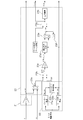
- FIG. 4 is a control block diagram of a voltage conversion motor rotation speed estimation unit 21, a motor OFF time calculation unit 22, and a pump discharge side pressure estimation unit 23 in the brake control unit BCU of the first embodiment.
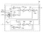
- FIG. 3 is a control block diagram of a motor model rotation speed estimation unit 24 in the brake control unit BCU of the first embodiment.
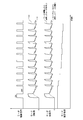
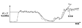
- 6 is a flowchart illustrating a flow of a pump discharge side pressure calculation process in the brake control unit BCU according to the first embodiment. It is a time chart of the motor rotation speed of Example 1, motor electromotive force, and a motor estimated load. 3 is a time chart of pump discharge side pressure according to the first embodiment.
- FIG. 7 is a control block diagram of a voltage conversion motor rotation speed estimation unit 21, a motor OFF time calculation unit 22, and a pump discharge side pressure estimation unit 23 in the brake control unit BCU of the second embodiment. It is a flowchart which shows the flow of the pump discharge side pressure calculation process in the brake control unit BCU of Example 2.
- Example 4 It is a time chart of the rotation speed difference integral value in Example 2, motor rotation speed, and pump discharge side pressure. It is a flowchart which shows the flow of the pump discharge side pressure calculation process in the brake control unit BCU of Example 3. It is a time chart of the voltage conversion motor rotation speed in Example 3, and a pump discharge side pressure. It is a time chart of the motor drive signal and pump discharge side pressure before the vehicle behavior stability control intervention in Example 4.
- FIG. 1 is a configuration diagram of the brake control device according to the first embodiment.
- the hydraulic control unit HU adjusts the braking force applied to each wheel of the vehicle.
- the hydraulic pressure control unit HU is based on commands from the brake control unit BCU, the left rear wheel wheel cylinder W / C (RL), the right front wheel wheel cylinder W / C (FR), and the left front wheel wheel cylinder W / C. (FL) Increase / decrease or maintain each hydraulic pressure of wheel cylinder W / C (RR) on the right rear wheel.
- the hydraulic control unit HU has a piping structure called X piping, which is composed of two systems, a P system and an S system.
- part described in FIG. 1 shows P system
- S shows S system
- RL, FR, FL, RR is a left rear wheel, a right front wheel, a left front wheel, and a right rear. Indicates that it corresponds to a ring.
- the description of P, S or RL, FR, FL, RR is omitted when the P, S system or each wheel is not distinguished.
- the hydraulic control unit HU uses a closed hydraulic circuit.
- the “closed hydraulic circuit” refers to a hydraulic circuit that returns the brake fluid supplied to the wheel cylinder W / C to the reservoir tank RSV via the master cylinder M / C.
- the hydraulic circuit that can return the brake fluid supplied to the wheel cylinder W / C directly to the reservoir tank RSV without passing through the master cylinder M / C is called “Open hydraulic circuit”. That's it.
- the brake pedal BP is connected to the master cylinder M / C via the input rod IR.
- the pedal depression force input to the brake pedal BP is boosted by the brake booster BB.
- the master cylinder M / C generates brake fluid pressure according to the output of the brake booster BB.
- a wheel cylinder W / C (FL) for the left front wheel FL and a wheel cylinder W / C (RR) for the right rear wheel RR are connected to the P system.
- the S system is connected to the wheel cylinder W / C (RL) of the left rear wheel RL and the wheel cylinder W / C (FR) of the right front wheel FR.
- the P system and the S system are provided with oil pumps (pumps) PP and PS.
- the oil pumps PP and PS are driven by one motor M.
- the motor M is a direct current motor.
- the oil pumps PP and PS are plunger pumps.
- the pipeline 2S is branched into pipelines 2RL and 2FR, the pipeline 2RL is connected to the wheel cylinder W / C (RL), and the pipeline 2FR is connected to the wheel cylinder W / C (FR).
- the pipe line 2P branches into pipe lines 2FL and 2RR, the pipe line 2FL is connected to the wheel cylinder W / C (FL), and the pipe line 2RR is connected to the wheel cylinder W / C (RR).
- a gate-out valve 3 which is a normally open type proportional control valve is provided.
- a pressure sensor 17 for detecting the master cylinder hydraulic pressure is provided at a position closer to the master cylinder side than the gate-out valve 3P of the pipe line 1P of the P system.
- a pipeline 4 is provided in parallel with the gate-out valve 3.
- a check valve 5 is provided on the pipeline 4. The check valve 5 allows the flow of brake fluid from the master cylinder M / C to the wheel cylinder W / C and prohibits the flow in the opposite direction.
- a solenoid-in valve 6 which is a normally open proportional control valve corresponding to each wheel cylinder W / C is provided on the pipe line 2.
- a pipe 7 is provided in parallel with the solenoid-in valve 6.
- a check valve 8 is provided on the pipeline 7. The check valve 8 allows the brake fluid to flow in the direction from the wheel cylinder W / C toward the master cylinder M / C, and prohibits the flow in the opposite direction.
- a discharge valve 10 is provided on the pipeline 9.
- the discharge valve 10 allows the flow of brake fluid in the direction from the oil pump P toward the pipe 2 and prohibits the flow in the opposite direction.
- the position on the master cylinder side of the gate line 1 relative to the gate-out valve 3 of the pipe line 1 and the suction side of the oil pump P are connected by a pipe line 11 and a pipe line 12.
- a pressure regulating reservoir 13 is provided between the pipe line 11 and the pipe line 12.
- a position on the wheel cylinder side of the solenoid valve 6 in the pipeline 2 and the pressure adjusting reservoir 13 are connected by a pipeline 14.
- the pipeline 14S branches to pipelines 14RL and 14FR, and the pipeline 14P branches to pipelines 14FL and 14RR and is connected to the corresponding wheel cylinder W / C.
- a solenoid-out valve 15 that is a normally closed solenoid valve is provided on the pipeline 14.
- the pressure regulating reservoir 13 includes a reservoir piston (piston) 13a, a reservoir spring 13b, and a check valve 16.
- the reservoir piston 13a is provided so as to be able to stroke up and down in the reservoir.
- the reservoir piston 13a descends as the amount of brake fluid flowing into the reservoir increases and rises as the amount of brake fluid decreases.
- the reservoir spring 13b biases the reservoir piston 13a in the upward direction.
- the check valve 16 includes a ball valve (valve element) 16a and a valve seat 16b.
- the ball valve 16a is provided integrally with the reservoir piston 13a and moves up and down according to the stroke of the reservoir piston 13a.
- the ball valve 16a is urged in the downward direction by a valve spring (not shown).
- the elastic force of the valve spring is set to be weaker than the elastic force of the reservoir spring 13b.
- the valve seat 16b contacts the ball valve 16a when the ball valve 16a is lowered.
- the reservoir piston 13a descends against the urging force of the reservoir spring 13b when brake fluid flows from the conduit 14. As a result, the brake fluid flows into the reservoir.
- the brake fluid that has flowed into the reservoir is supplied to the suction side of the oil pump P via the conduit 12.
- the ball valve 16a is also lowered as the reservoir piston 13a is lowered, and is seated (contacted) on the valve seat 16b by the urging force of the valve spring.
- the check valve 16 is closed.
- the check valve 16 is closed to the pressure adjustment reservoir 13 from the master cylinder side. The brake fluid inflow stops.
- the reservoir piston 13a rises due to the pressure in the conduit 12 being lowered.
- the ball valve 16a is also raised and separated from the valve seat 16b.
- the check valve 16 is opened. Therefore, since the master cylinder side and the suction side of the oil pump P are communicated with each other, the brake fluid flows from the master cylinder side into the pressure regulating reservoir 13.
- the check valve 16 is closed when the pressure in the pipe line 11 exceeds a predetermined pressure, such as when the driver depresses the brake pedal BP. As a result, the brake fluid does not flow from the master cylinder side to the pressure regulating reservoir 13, and high pressure can be prevented from acting on the suction side of the oil pump P.
- ABS control The brake control unit BCU performs anti-lock brake (ABS) control as brake control.
- ABS control detects that a wheel has become locked during brake operation by the driver, the wheel cylinder hydraulic pressure is reduced, held, and increased in order to generate the maximum braking force while preventing the wheel from locking. It is a control that repeats the pressure.
- ABS pressure reduction control the solenoid in valve 6 is closed and the solenoid out valve 15 is opened from the state shown in FIG. 1 (each valve is OFF), and the brake fluid in the wheel cylinder W / C is released to the pressure adjusting reservoir 13 to release the foil. Reduce cylinder hydraulic pressure.
- ABS holding control the wheel cylinder hydraulic pressure is held by closing both the solenoid-in valve 6 and the solenoid-out valve 15.
- ABS pressure increase control the solenoid in valve 6 is controlled in the opening direction and the solenoid out valve 15 is closed, and the brake fluid is supplied from the master cylinder M / C to the wheel cylinder W / C to increase the wheel cylinder hydraulic pressure.
- the hydraulic pressure control unit HU of the first embodiment can perform automatic brake control such as vehicle behavior stability control, brake assist control, and preceding vehicle follow-up control by operating each valve and oil pump P as brake control. It is.
- the vehicle behavior stabilization control is a control for stabilizing the vehicle behavior by controlling the wheel cylinder hydraulic pressure of a predetermined wheel to be controlled when it is detected that the oversteer tendency or the understeer tendency becomes strong when the vehicle turns.
- the brake assist control is a control in which the wheel cylinder W / C generates a pressure higher than the pressure actually generated in the master cylinder M / C when the driver operates the brake.
- the preceding person follow-up control is a control that automatically generates a braking force according to the relative relationship with the preceding vehicle by auto-cruise control.
- the brake control unit BCU determines the target of the wheel cylinder W / C based on signals from the pressure sensor 17 and other in-vehicle sensors (wheel speed sensor, steering angle sensor, yaw rate sensor, lateral acceleration sensor, etc.) in each brake control described above. Generate hydraulic pressure. Then, each valve and the motor M of the hydraulic pressure control unit HU are driven so that the wheel cylinder hydraulic pressure matches the target hydraulic pressure.
- the gate-out valve 3 and the solenoid-in valve 6 are PWM controlled with a constant control cycle, and the motor M is ON / OFF controlled with a constant control cycle. The control period of the motor M is set to be sufficiently longer than the PWM control.
- the solenoid out valve 15 is ON / OFF controlled.
- the brake control unit BCU includes a motor driving unit 20 that drives the motor M ON / OFF.
- the desired differential pressure is generated upstream and downstream of the gate-out valve 3 by closing or controlling the gate-out valve 3 in the closing direction (proportional control), and the wheel cylinder hydraulic pressure is set as the target. Match with hydraulic pressure. For this reason, in order to set the differential pressure to a desired value, it is necessary to know the actual differential pressure.
- the hydraulic pressure control unit HU of the first embodiment is provided with the pressure sensor 17 on the upstream side of the gate-out valve 3, the downstream side of the gate-out valve 3, that is, the discharge side of the oil pump P Since no pressure sensor is provided, the pressure on the discharge side of the oil pump P (hereinafter referred to as pump discharge side pressure) is estimated based on other parameters.
- the pump discharge side pressure is estimated as described below with the aim of accurately estimating the pump discharge side pressure without adding an additional member such as a pressure sensor. Even when proportional control of the gate-out valve 3 is not performed, it is important for improving the controllability of the wheel cylinder hydraulic pressure that the pump discharge side pressure can be accurately estimated.
- it is possible to estimate the pressure on the discharge side of the hydraulic pressure source from the deceleration generated in the vehicle there is a problem of a decrease in estimation accuracy.
- FIG. 2 shows a voltage-converted motor rotation number estimation unit (motor actual rotation number calculation unit, motor rotation number calculation unit, motor rotation number estimation unit) 21 and motor OFF time calculation unit (drive cycle) in the brake control unit BCU of the first embodiment.
- 7 is a control block diagram of a calculation unit) 22 and a pump discharge side pressure estimation unit (fluid pressure source discharge side pressure estimation unit) 23.
- FIG. Voltage conversion motor speed estimation part
- the voltage conversion motor rotation speed estimation unit 21 estimates the voltage conversion motor rotation speed ⁇ raw from the voltage across the terminals of the motor M (hereinafter referred to as motor end voltage) E.
- the voltage conversion motor rotation speed estimation unit 21 calculates the voltage conversion motor rotation speed ⁇ raw by multiplying the motor end voltage E by 1 / K e .
- K e is the counter electromotive force constant.
- the motor rotational speed ⁇ the counter electromotive force constant the motor electromotive force
- the motor rotational speed can be obtained if the motor electromotive force and the counter electromotive force constant are known.
- the motor M is ON / OFF controlled, and the motor electromotive force cannot be obtained when the motor M is ON.
- the motor end voltage is equal to the motor electromotive force when OFF, the motor rotation speed can be obtained from the motor end voltage and the counter electromotive force constant when OFF.
- the voltage-converted motor rotation speed ⁇ raw is output to the pump discharge side pressure estimation section 23 and the motor model rotation speed estimation section (motor model rotation speed calculation section) 24 (see FIG. 3).
- the motor OFF time calculation unit 22 calculates the motor OFF time T off from the motor drive signal.
- the motor OFF time calculation unit 22 includes an ON ⁇ OFF timing detection unit 22a, an OFF ⁇ ON timing detection unit 22b, and a motor OFF time calculation unit 22c.
- the ON ⁇ OFF timing detection unit 22a detects a motor ON ⁇ OFF timing f ON_OFF that is a timing at which the motor M is switched from ON to OFF from the motor drive signal.
- the OFF ⁇ ON timing detection unit 22b detects a motor OFF ⁇ ON timing f OFF_ON that is a timing at which the motor M is switched from OFF to ON from the motor drive signal.
- the motor OFF time calculation unit 22c calculates a motor OFF time T OFF that is an OFF time of the motor M from the motor ON ⁇ OFF timing f ON_OFF and the motor OFF ⁇ ON timing f OFF_ON .
- Motor OFF time T off is outputted to the pump discharge side pressure estimating unit 23, the motor OFF ⁇ ON timing f OFF_ON is outputted to the pump discharge side pressure estimating unit 23 and the motor model rotational speed estimation unit 24.
- the pump discharge side pressure estimation unit 23 is based on the voltage conversion motor rotational speed ⁇ raw , the estimated motor model rotational speed ⁇ estimated by the motor model rotational speed estimation unit 24, the motor OFF time T off, and the motor OFF ⁇ ON timing f OFF_ON. Thus, the pump discharge side pressure P est is estimated.
- the rotation speed difference calculation block 23a calculates a rotation speed difference ⁇ by subtracting the voltage conversion motor rotation speed ⁇ raw from the motor model estimated rotation speed ⁇ .
- the rotation speed difference change rate calculation block 23b calculates a rotation speed difference change rate ⁇ / T off obtained by dividing the rotation speed difference ⁇ by the motor OFF time T off .
- the motor estimated load correction value change rate calculation block 23c calculates the motor estimated load correction value change rate ⁇ T load_core by multiplying the rotation speed difference change rate ⁇ / T off by the motor estimated load correction coefficient C corr .
- the correction output determination block 23d outputs the motor estimated load correction value change rate ⁇ T load_corr calculated by the motor estimated load correction value change rate calculation block 23c when the motor OFF ⁇ ON timing f OFF_ON is input. Otherwise , 0 is output as the motor estimated load correction value change rate ⁇ T load_corr .
- Estimated motor load selection block 23e is the estimated motor load correction value T Load_corr by adding the previous value of the corrected output decision block estimated motor load correction value change rate is output from 23d ⁇ T load_corr and the estimated motor load correction value T Load_corr Calculate.
- the previous value calculation block 23f calculates the previous value of the motor estimated load correction value Tload_corr .
- Estimated motor load calculation block (motor state estimator, the load estimating unit) 23 g calculates the estimated motor load T load by adding the motor load based constant preset and the estimated motor load correction value T load_corr.
- the estimated motor load T load is output to the subsequent pressure conversion block 23h and the motor model rotation speed estimation unit 24.
- the pressure conversion block 23h calculates the pump discharge side pressure P est by converting the estimated motor load T load into a pressure.
- FIG. 3 is a control block diagram of the motor model rotation speed estimation unit 24 in the brake control unit BCU of the first embodiment.
- the motor model rotational speed estimation unit 24 is preset according to the characteristics of the motor M based on the motor end voltage E, the voltage conversion motor rotational speed ⁇ raw , the motor OFF ⁇ ON timing f OFF_ON, and the motor estimated load T load .
- a motor model estimated rotational speed ⁇ is estimated from the motor model.
- the motor model rotational speed estimation unit 24 includes a motor rotational speed estimation model 25 and a motor current estimation model 26 as motor models.
- the motor rotational speed estimation model 25 inputs the motor estimated load T load , the OFF ⁇ ON timing f OFF_ON , the voltage conversion motor rotational speed ⁇ raw, and the estimated motor current I, and outputs the estimated motor model rotational speed ⁇ .
- Motor current estimation model 26 inputs the induced electromotive force E m of the motor end voltage E and the motor M, and outputs the estimated motor current I.
- the motor rotational speed estimation model 25 constitutes a model for obtaining the motor model estimated rotational speed ⁇ from the following relational expression representing the mechanical characteristics of the motor M.
- T K t * I
- T rot J * d ⁇ / dt
- T is the motor torque
- K t the motor torque constant
- I the motor estimated current
- T rot is the rotational torque
- J is the motor inertia moment
- d ⁇ / dt is the motor angular acceleration
- T f is the rotational speed dependent torque
- T load is an estimated motor load
- K f is a motor friction constant.
- the rotation speed switching block (motor rotation speed correction unit) 25a outputs the voltage conversion motor rotation speed ⁇ raw as the motor model estimated rotation speed when the motor OFF ⁇ ON timing f OFF_ON is input, and otherwise the input motor
- the model estimated rotation speed ⁇ is output as it is.
- Motor torque calculation block 25b calculates the motor torque T is multiplied by a motor torque constant K t to the estimated motor current I.
- Gain multiplication block 25c calculates the rotational speed-dependent torque T f is multiplied by a motor friction constant K f to the motor model estimation rotational speed omega.
- the rotational torque calculation block 25d calculates the rotational torque T rot by subtracting the motor estimated load T load and the rotational speed dependent torque T f from the motor torque T.
- the motor angular acceleration calculation block 25e calculates the motor angular acceleration d ⁇ / dt by dividing the rotational torque T rot by the motor moment of inertia J.
- the motor rotation speed calculation block 25f calculates the motor model estimated rotation speed ⁇ by integrating the motor angular acceleration d ⁇ / dt.
- the motor model estimated rotation speed ⁇ is output to the back electromotive force calculation block 25g and the pump discharge side pressure estimation unit 23 in the subsequent stage.
- Counter electromotive force calculation block 25g calculates the counter electromotive force (induced electromotive force) E m by multiplying the back electromotive force constant K e to the motor model estimation rotational speed omega.
- the motor current estimation model 26 constitutes a model for obtaining the motor estimated current I from the following relational expression representing the electrical characteristics of the motor M.
- E R is the voltage drop due to the motor resistance
- E L is a voltage drop due to inductance of the motor
- the E m is the counter-electromotive force
- dI / dt is the motor current change rate
- K e is a counter electromotive force constant.
- the motor resistance voltage calculation unit 26a calculates the voltage drop E R due to the motor resistance by multiplying the estimated motor current I by the internal resistance R of the motor M.
- Brush voltage drop calculation block 26b from the motor end voltage E by subtracting the voltage drop E R by the counter-electromotive force E m and the motor resistance calculating the voltage drop E L due to the inductance of the motor.
- Motor current change rate calculating section 26c calculates a motor current change rate dI / dt by dividing the voltage drop E L due to the inductance of the motor in self-inductance L.
- the motor current calculation block 26d calculates the motor estimated current I by integrating the motor current change rate dI / dt.
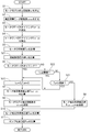
- FIG. 4 is a flowchart showing the flow of the pump discharge side pressure calculation process in the brake control unit BCU of the first embodiment. Each step will be described below.
- the motor model rotational speed estimation unit 24 estimates the motor model estimated rotational speed ⁇ .
- the voltage conversion motor rotation speed estimation unit 21 estimates the voltage conversion motor rotation speed ⁇ raw .
- the motor OFF ⁇ ON timing f OFF_ON is detected by the OFF ⁇ ON timing detection unit 22b of the motor OFF time calculation unit 22.
- the ON ⁇ OFF timing detection unit 22a of the motor OFF time calculation unit 22 detects the motor ON ⁇ OFF timing f ON_OFF .
- step S5 the motor OFF time calculation unit 22c of the motor OFF time calculation unit 22 calculates the motor OFF time T off.
- step S6 the correction output determination block 23d of the pump discharge side pressure estimation unit 23 determines whether or not the motor OFF ⁇ ON timing f OFF_ON has been input. If YES, the process proceeds to step S7. If NO, the process proceeds to step S8.
- step S7 the motor estimated load correction value T load_corr is calculated in the motor estimated load selection block 23e of the pump discharge side pressure estimating unit 23.
- the motor estimated load correction value T load_corr is a value obtained by adding the motor estimated load correction value change rate ⁇ T load_corr and the previous value of the motor estimated load correction value T load_corr .
- a motor estimated load correction value T load_corr is calculated in the motor estimated load selection block 23e of the pump discharge side pressure estimating unit 23. Since it is not the motor OFF ⁇ ON timing, the motor estimated load correction value T load_corr is the previous value.
- the voltage conversion motor rotation speed ⁇ raw is output as the motor model estimated rotation speed.
- the estimated motor load T load is calculated in the estimated motor load calculation block 23g of the pump discharge side pressure estimation unit 23.
- the pump discharge side pressure P est is calculated in the pressure conversion block 23h of the pump discharge side pressure estimation unit 23.
- the motor electromotive force of the DC motor can be obtained by multiplying the motor rotational speed and the counter electromotive force constant. In other words, if the motor electromotive force and the electromotive force constant are known, the motor rotation speed can be known.
- motor ON / OFF control a switch is provided in a part of a circuit, and the motor is controlled by turning it ON / OFF. When the switch is ON, the motor electromotive force cannot be known, but when the switch is OFF, the motor electromotive force can be determined by measuring the voltage between the motor terminals. That is, when the switch is OFF, the motor speed can be known from the voltage between the motor terminals.
- the motor model rotational speed estimation unit 24 uses a motor M plant model (motor rotational speed estimation model 25 and motor current estimation model 26) having a parameter of the motor estimated load T load , and the motor rotational speed. (Motor model estimated rotation speed ⁇ ) is estimated. Further, the voltage conversion motor rotation speed estimation unit 21 calculates the actual motor rotation speed (voltage conversion motor rotation speed ⁇ raw ) while the switch is OFF.
- the difference (rotational speed difference ⁇ ) between the motor model estimated rotational speed ⁇ and the voltage-converted motor rotational speed ⁇ raw before the motor M is turned OFF ⁇ ON is estimated as an estimation error of the motor estimated load T load.
- the motor estimated load correction value change rate ⁇ T load_corr is calculated by multiplying the rotational speed difference ⁇ by the motor OFF time T off and the motor estimated load correction coefficient C corr , and the estimated motor load in the model according to ⁇ T load_corr Increase or decrease the correction value T load_corr . That is, by correcting the motor estimated load T load so as to eliminate the rotation speed difference ⁇ , the motor estimated load T load can be brought close to the actual motor load.
- the motor model estimated rotational speed ⁇ is matched with the voltage conversion motor rotational speed ⁇ raw at the timing of motor OFF ⁇ ON.
- the motor torque changes in proportion to the pump discharge pressure. Since the pump discharge pressure is proportional to the pump discharge side pressure P est , the pump discharge side pressure is calculated by substituting the estimated motor load T load obtained by adding the motor estimated load correction value T load_corr to the motor load base constant into the pressure conversion formula. P est can be estimated.
- FIG. 5 is a time chart of the motor rotation speed, the motor electromotive force, and the motor estimated load according to the first embodiment.
- the motor rotation speed (voltage conversion motor rotation speed ⁇ raw ) estimated from the motor end voltage when the motor is OFF is substantially equal to the actual motor rotation speed.
- the motor model estimated rotational speed ⁇ estimated from the motor model is processed so as to coincide with the voltage-converted motor rotational speed ⁇ raw at each motor OFF ⁇ ON timing.
- the motor estimated load correction value T load_corr and the motor estimated load T load are corrected by the motor estimated load correction value ⁇ T load_corr corresponding to ⁇ .
- ⁇ > ⁇ raw that is, when ⁇ is a positive value
- the motor estimated load correction value T load_corr is increased and corrected by the positive motor estimated load correction value ⁇ T load_corr corresponding to ⁇ , and the motor estimated load T load is corrected to be increased.
- the motor estimated load correction value T load_corr is decreased and corrected by the negative motor estimated load correction value ⁇ T load_corr corresponding to ⁇ , and the motor estimated load T load is decreased and corrected.
- the estimation accuracy of the estimated motor load T load is improved, so that the pump discharge side pressure P est obtained by converting the estimated motor load T load into a pressure can be accurately estimated.
- the cost increase by addition of additional members, such as a pressure sensor can be suppressed.
- the pump discharge side pressure P est since the pump discharge side pressure P est can be accurately estimated, the pump discharge side pressure P est is made to follow the actual pump discharge side pressure (measured value) with a slight delay. Can do.
- the pump discharge side pressure estimation unit 23 calculates the rotational speed difference change rate ⁇ / T off by dividing the rotational speed difference ⁇ between the motor model estimated rotational speed ⁇ and the voltage conversion motor rotational speed ⁇ raw by the motor OFF time T off.
- the motor estimated load correction value change rate ⁇ T load_corr is calculated by multiplying the rotational speed difference change rate ⁇ / T off by the motor estimated load correction coefficient C corr .
- the rotation speed switching block 25a When the motor OFF ⁇ ON timing f OFF_ON is input, the rotation speed switching block 25a outputs the voltage conversion motor rotation speed ⁇ raw as the motor model estimated rotation speed ⁇ .
- the motor end voltage is not equal to the motor electromotive force.
- the motor model estimated rotational speed ⁇ matches the actual motor rotational speed.
- the estimation accuracy of the model estimated rotational speed ⁇ can be improved. Since the motor end voltage is equal to the motor electromotive force even when the motor is off, the actual rotational speed may be corrected whenever the motor is off, but the timing immediately before turning on the motor M is the largest and the difference of ⁇ coming out. Therefore, by correcting the motor model estimated rotation speed ⁇ with the voltage-converted motor rotation speed ⁇ raw at the motor OFF ⁇ ON timing, it is possible to suppress a decrease in estimation accuracy of the motor estimated load T load .
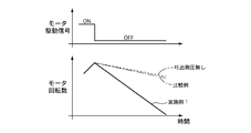
- FIG. 7 is a time chart of the amount of brake fluid in the reservoir, the motor speed, and the pump discharge side pressure in the comparative example.
- the (inertia) rotation speed of the motor decreases according to the motor load.
- the oil pump pumps all of the brake fluid in the reservoir at time t2
- there is no brake fluid to be discharged so no load is generated on the motor even when pressure is generated on the discharge side. Is inertial rotating in a state close to idling (see FIG. 8). Therefore, since the influence of the pressure on the discharge side does not appear in the rotation speed or voltage of the motor, the estimated motor load T load is smaller than the actual motor load.
- the pump discharge side pressure P est estimated from the motor OFF ⁇ ON timing at time t3 greatly deviates from the actually measured value.
- the time t4 to t6 is the same as the time t1 to t3, and no load is generated on the motor. Therefore, the pump discharge side pressure P est estimated at the time t5 is greatly different from the actual measurement value.
- the pump discharge side pressure P est cannot be estimated.
- it is possible to always store the brake fluid in the reservoir but in this case, it is necessary to open the solenoid-out valve, and the pedal feel deteriorates due to the suction of the brake pedal, and the wheel cylinder hydraulic pressure decreases. This causes a decrease in deceleration.
- the check valve 16 is opened when the motor M rotates. Accordingly, since the master cylinder side and the suction side of the oil pump P are in communication, the oil pump P sucks, pressurizes and discharges the brake fluid from the master cylinder M / C. That is, regardless of the presence or absence of the brake fluid in the pressure adjusting reservoir 13, the oil pump P always discharges the brake fluid while the motor M is rotating. As a result, a load corresponding to the pressure on the discharge side (pipe line 2) is always applied to the oil pump P, and the motor rotation speed decreases according to the motor load (see FIG. 8).
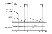
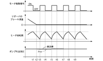
- FIG. 9 is a time chart of the brake fluid amount of the pressure regulating reservoir, the motor rotation speed, and the pump discharge side pressure in the first embodiment.
- the pump discharge side pressure P est approximated to the actual measurement value can be estimated.
- the time t4 to t5, the time t6 to t7, and the time t8 to t9 are the same as the time t1 to t3, and the pump discharge side pressure P est estimated at the times t5, t7, and t9 is a value that approximates the actually measured value.
- Example 1 A hydraulic pressure source (oil pump P) for increasing the wheel cylinder hydraulic pressure by sending it to the wheel cylinder W / C using the brake fluid in the master cylinder M / C or the pressure regulating reservoir 13, and the hydraulic pressure
- the motor M that drives the power source, the motor drive unit 20 that drives the motor M ON / OFF, and the voltage conversion that calculates the motor rotation speed ⁇ raw that is the actual rotation speed of the motor M based on the voltage across the terminals of the motor M
- a motor rotation speed estimation unit 21 a motor model rotation speed estimation unit 24 that estimates a motor model estimated rotation speed ⁇ that is a model rotation speed of the motor M from a preset motor model based on the characteristics of the motor M, and a motor model rotation
- the load applied to the motor M based on the rotational speed difference ⁇ that is the difference between the motor model estimated rotational speed ⁇ estimated by the speed estimating unit 24 and the voltage-converted motor rotational speed ⁇ raw calculated by the voltage-converted motor rotational speed estimating unit 21
- the pressure regulating reservoir 13 is provided in an oil passage (the pipelines 11 and 12) between the master cylinder M / C and the hydraulic pressure source, and is stored inside.
- the hydraulic pressure source is supplied with brake fluid from the master cylinder M / C via the pressure regulating reservoir 13. Therefore, the pump discharge side pressure P est can always be estimated while the motor M is rotating.
- the motor model estimated rotational speed ⁇ estimated by the motor model rotational speed estimating unit 24 is used as the voltage converted motor rotational speed ⁇ calculated by the voltage converted motor rotational speed estimating unit 21.
- a rotation speed switching block 25a for correcting based on raw is provided. Therefore, the estimation accuracy of the motor model estimated rotation speed ⁇ can be improved.
- a motor OFF time calculation unit 22 that calculates a motor OFF time T off that represents the ON / OFF drive cycle of the motor M is provided, and the pump discharge side pressure estimation unit 23 Based on the rotational speed difference ⁇ and the motor OFF time T off calculated by the motor OFF time calculator 22, the estimated motor load T load is estimated.
- the hydraulic pressure source is an oil pump P. Therefore, since the pressure at the time of pump-up can be estimated with high accuracy, the control accuracy of brake control can be improved.
- Oil pump P that sucks brake fluid in the master cylinder M / C or the pressure regulating reservoir 13 and discharges it to the wheel cylinder W / C side, a motor M that drives the oil pump P, and a motor that drives the motor M
- the drive unit 20 the voltage conversion motor rotation number estimation unit 21 that calculates the voltage conversion motor rotation number ⁇ raw that is the rotation number of the motor M based on the voltage between the terminals of the motor M, and the electric characteristics of the motor M
- the motor model rotational speed estimation unit 24 that calculates the motor model estimated rotational speed ⁇ that is the model rotational speed, the motor model estimated rotational speed ⁇ calculated by the motor model rotational speed estimation unit 24, and the voltage conversion motor rotational speed estimation unit 21 and the estimated motor load calculating block 23g from the difference between the calculated voltage conversion motor revolution number omega raw estimating the estimated motor load T load in the state of the motor M, Oirupo based on the estimated motor estimated load T load
- the voltage conversion motor rotation speed estimation unit 21 calculates the actual rotation speed as the voltage conversion motor rotation speed ⁇ raw . Therefore, the estimation accuracy of the motor estimated load T load can be improved by using the actual rotational speed.
- the motor estimated load calculation block 23g is calculated by the motor model estimated rotational speed ⁇ calculated by the motor model rotational speed estimating unit 24 and the voltage conversion motor rotational speed estimating unit 21.
- the estimated motor load T load is estimated based on the rotational speed difference ⁇ that is a deviation from the voltage converted motor rotational speed ⁇ raw . Therefore, the estimation accuracy of the motor estimated load T load can be improved.
- the pressure regulating reservoir 13 is provided in an oil passage (the pipelines 11 and 12) between the master cylinder M / C and the oil pump P, and is stored therein.
- the oil pump P sucks brake fluid from the master cylinder M / C via the pressure regulating reservoir 13. Therefore, the pump discharge side pressure P est can always be estimated while the motor M is rotating.
- Voltage conversion motor rotation speed estimation section 21 motor model rotation speed estimation section 24 for calculating motor model estimated rotation speed ⁇ , which is the model rotation speed of motor M from the electrical characteristics of motor M, and motor model rotation speed estimation section 24
- the estimated motor model load T load corresponding to the load applied to the oil pump P is estimated from the difference between the estimated motor model speed ⁇ calculated by the above and the voltage converted motor speed ⁇ raw estimated by the voltage converted motor speed estimator 21.
- Motor A load calculation block 23g, the pump discharge side pressure estimating unit 23 for estimating a pump discharge side pressure P est is the pressure at the discharge side of the oil pump P based on the estimated motor load T load, comprising a. Therefore, it is possible to accurately estimate the pump discharge side pressure P est without adding an additional member.
- a motor OFF time calculation unit 22 that calculates a motor OFF time T off that represents the ON / OFF drive cycle of the motor M
- the motor estimated load calculation block 23g includes: The rotation speed difference ⁇ that is the difference between the motor model estimated rotation speed ⁇ calculated by the motor model rotation speed estimation section 24 and the voltage conversion motor rotation speed ⁇ raw estimated by the voltage conversion motor rotation speed estimation section 21 and the motor OFF
- the estimated motor load T load is estimated based on the motor OFF time T off calculated by the time calculation unit 22. Therefore, the estimation accuracy of the motor estimated load T load can be improved.
- the oil pump P sucks brake fluid from the master cylinder M / C or the pressure regulating reservoir 13, and the pressure regulating reservoir 13 is an oil passage (pipe). It is provided in the oil passage (pipes 11, 12) between the master cylinder M / C and the suction side of the oil pump P among the passages 1, 11, 12), and operates according to the amount of brake fluid stored inside.
- a reservoir piston 13a and a ball valve 16a that operates in conjunction with the reservoir piston 13a, opens the oil passage when the reservoir piston 13a is raised, and closes the oil passage when the reservoir piston 13a is lowered are provided. Therefore, the pump discharge side pressure P est can always be estimated while the motor M is rotating.
- FIG. 10 is a control block diagram of the voltage conversion motor rotation speed estimation unit 21, the motor OFF time calculation unit 22, and the pump discharge side pressure estimation unit 23 in the brake control unit BCU of the second embodiment.
- the rotational speed difference integral value calculation block 23i integrates the rotational speed difference ⁇ to calculate the rotational speed difference integral value I ⁇ .
- FIG. 11 is a flowchart showing the flow of the pump discharge side pressure calculation process in the brake control unit BCU of the second embodiment. Steps that perform the same processing as in the flowchart of FIG. 4 are denoted by the same step numbers and description thereof is omitted.
- step S21 the rotational speed difference integral value calculation block 23i of the pump discharge side pressure estimating unit 23 calculates the rotational speed difference integral value I omega.
- step S22 in the correction output determination block 23d of the pump discharge side pressure estimation unit 23, it is determined whether or not the rotational speed difference integral value I ⁇ has reached a threshold value. If YES, the process proceeds to step S23, and if NO, the process proceeds to step S8.
- Example 1 [Correction of estimated motor load according to the speed difference integral value]
- the timing at which the motor M was switched from OFF to ON was used as a correction trigger, and the estimated motor load T load was corrected by the estimated motor load correction value T load_corr corresponding to the rotation speed difference ⁇ .
- the motor estimated load T load is corrected using the timing at which the rotational speed difference integral value I ⁇ reaches the threshold as a correction trigger.
- the rotational speed difference integral value I ⁇ reaches the threshold value while the motor is OFF, it can be determined that the difference between the motor model estimated rotational speed ⁇ and the actual motor rotational speed is large.
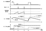
- FIG. 12 is a time chart of the rotational speed difference integral value, the motor rotational speed, and the pump discharge side pressure in the second embodiment.
- the rotational speed difference integral value I ⁇ is reset, and the motor model estimated rotational speed ⁇ is made to coincide with the voltage conversion motor rotational speed ⁇ raw .
- the voltage conversion motor rotation speed ⁇ raw is the same as the actual measurement.
- the motor estimated load T load is increased and corrected by the motor estimated load correction value T load_corr corresponding to the rotation speed difference ⁇ , and the pump discharge side pressure P est is corrected.
- the pump discharge side pressure P est approaches the measured value.
- the motor estimated load Tload is corrected to be increased.
- the pump discharge side pressure P est matches the measured value.
- the motor estimated load T load is not corrected until the motor M is switched from OFF to ON at time t4 after the motor M is switched from ON to OFF at time t1.
- the motor estimated load T in order to correct the motor estimated load T load even when the rotational speed difference integral value I ⁇ reaches the threshold, the motor estimated load T waits for the motor M to switch from OFF to ON. as compared with the case of correcting the load, it can be improved followability to the measured value of the pump discharge side pressure P est.
- Example 2 the following effects are exhibited.
- the pump discharge side pressure estimation unit 23 estimates the load applied to the motor M by integrating the rotation speed difference ⁇ . Therefore, it is possible to improve the followability with respect to the actually measured value of the pump discharge side pressure P est .
- a motor OFF time calculation unit 22 that calculates a motor OFF time T off that represents the ON / OFF drive cycle of the motor M is provided, and the pump discharge side pressure estimation unit 23 includes: estimating the estimated motor load T load based on the motor OFF time T off, which is calculated by the integral value of the rotation speed difference ⁇ rotational speed difference integral value I omega motor OFF time calculation unit 22.
- the estimation accuracy of the motor estimated load T load can be improved.
- the motor model estimated rotational speed ⁇ estimated by the motor model rotational speed estimating unit 24 is converted into the voltage converted motor rotational speed ⁇ calculated by the voltage converted motor rotational speed estimating unit 21.
- a rotation speed switching block 25a for correcting based on raw is provided. Therefore, the estimation accuracy of the motor model estimated rotation speed ⁇ can be improved.
- the estimated motor load calculating block 23g estimates the estimated motor load T load based on the rotation speed difference rotational speed difference integral value is an integral value of [Delta] [omega I omega. Therefore, it is possible to improve the followability with respect to the actually measured value of the pump discharge side pressure P est .
- the pressure regulating reservoir 13 is provided in an oil passage (the pipelines 11 and 12) between the master cylinder M / C and the oil pump P, and is stored therein.
- the oil pump P sucks brake fluid from the master cylinder M / C via the pressure regulating reservoir 13. Therefore, the pump discharge side pressure P est can always be estimated while the motor M is rotating.
- the estimated motor load calculating block 23g the motor calculated by the rotation speed difference integral value is an integration value of the rotational speed difference [Delta] [omega I omega motor OFF time calculator 22
- the estimated motor load T load is estimated based on the OFF time T off . Therefore, it is possible to improve the followability with respect to the actually measured value of the pump discharge side pressure P est .
- the oil pump P sucks brake fluid from the master cylinder M / C or the pressure regulating reservoir 13, and the pressure regulating reservoir 13 is included in the oil passage.
- a reservoir piston 13a that is provided between the master cylinder M / C and the suction side of the oil pump P and operates in accordance with the amount of brake fluid stored inside, and operates in conjunction with the reservoir piston 13a.
- a ball valve 16a that opens the oil passage when ascending and closes the oil passage when descending. Therefore, the pump discharge side pressure P est can always be estimated while the motor M is rotating.
- Example 3 The third embodiment is different from the first embodiment only in the configuration of the pump discharge side pressure estimation unit 23.
- the same components as those in the first embodiment are denoted by the same reference numerals, and illustration and description thereof are omitted.
- (Pump discharge side pressure estimation part) Corrected output decision block 23d, when the motor OFF ⁇ ON timing f OFF_ON is input, when the rotation speed difference integral value I omega has reached the threshold, or when the motor OFF time T off has reached the threshold, the estimated motor load
- the motor estimated load correction value change rate ⁇ T load_corr calculated by the correction value change rate calculation block 23c is output. Otherwise , 0 is output as the motor estimated load correction value change rate ⁇ T load_corr .
- the timing at which the motor M is switched from OFF to ON and the timing at which the rotational speed difference integral value I ⁇ reaches the threshold is used as a correction trigger.
- the estimated load T load is corrected. If the motor load decreases during inertial rotation of the motor M, the motor M idles. As shown in FIG. 14, by following the load estimation at regular intervals while the motor M is idling, the followability of the pump discharge side pressure P est to the measured value can be improved.
- Example 4 The fourth embodiment is different from the first embodiment in that the oil pump P is driven and the pump discharge side pressure P est is estimated before the brake control intervention.
- the same components as those in the first embodiment are denoted by the same reference numerals, and illustration and description thereof are omitted.
- increasing the estimation accuracy of the pump discharge side pressure P est can contribute to improving the control accuracy of each brake control.
- the brake control can be performed using the accurate pump discharge side pressure immediately after the control intervention, which is advantageous in accuracy.
- the motor M is turned before the brake control intervention, and the pump discharge side pressure P est is estimated.
- the motor M is rotated to estimate the pump discharge side pressure P est .
- vehicle behavior stabilization control is as follows.
- the brake control unit BCU calculates the yaw rate (steering angle conversion yaw rate) acting on the vehicle from the steering angle and the vehicle speed while the vehicle is running, and is the difference between the steering angle conversion yaw rate and the sensor value (actual measurement value) of the yaw rate sensor.
- the yaw rate difference is always calculated.
- the brake control unit BCU starts the vehicle behavior stabilization control when the yaw rate difference reaches the control intervention threshold.
- the control intervention threshold is set to positive and negative.
- the understeer tendency is strong.
- the front wheel inside the turn is set as the control target wheel, and the wheel cylinder hydraulic pressure of the control target wheel is increased.
- the target hydraulic pressure is determined according to the yaw rate difference.
- the oversteer tendency is strong.
- the front wheel outside the turn is set as the control target wheel, and the wheel cylinder hydraulic pressure of the control target wheel is increased.
- the target hydraulic pressure is determined according to the yaw rate difference. Thereby, an oversteer tendency can be suppressed.
- the pre-control intervention threshold having an absolute value smaller than the control intervention threshold is set to the positive side and the negative side, respectively.
- the motor M is switched from OFF to ON, and the pump discharge side pressure P est is estimated.
- the motor M is turned ON at regular intervals, and the ON time of the motor M is limited to the shortest time that the pump discharge side pressure P est can be estimated.
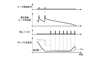
- FIG. 15 is a time chart of the motor drive signal and the pump discharge side pressure before the vehicle behavior stabilization control intervention in the fourth embodiment.
- the motor M is switched from OFF to ON, and the pump discharge side pressure P est is corrected.
- the pump discharge side pressure P est approaches the measured value. Since a certain time has elapsed from time t1 at time t2, the motor M is switched from OFF to ON again, and the pump discharge side pressure P est is corrected. The pump discharge side pressure P est further approaches the actually measured value. Since the yaw rate difference reaches the control intervention threshold at time t3, the wheel cylinder hydraulic pressure of the wheel to be controlled (turning inner front wheel) is increased by vehicle behavior stabilization control. At this time, since the pump discharge side pressure P est is corrected to a value close to the actually measured value, highly accurate vehicle behavior stability control can be performed using the accurate pump discharge side pressure immediately after the control intervention.
- the concrete structure of this invention is not limited to the structure shown in the Example, and is the range which does not deviate from the summary of invention. Any design changes are included in the present invention.
- the present invention can accurately estimate the pump discharge side pressure without providing a pressure sensor, but is also useful in a hydraulic control unit including a pressure sensor for detecting the pump discharge side pressure. In other words, by using the sensor value of the pressure sensor and using the pump discharge side pressure obtained by the estimation of the present invention when the pressure sensor fails, the brake control can be continued even when the pressure sensor fails, and the reliability of the device It can contribute to improvement.
Landscapes
- Engineering & Computer Science (AREA)
- Transportation (AREA)
- Mechanical Engineering (AREA)
- Regulating Braking Force (AREA)
Abstract
モータ特性から推定したモデル回転数と、モータの端子間電圧から推定した実回転数との差分に基づきモータにかかる負荷を推定し、推定した負荷に基づき液圧源の吐出側の圧力を推定する。
Description
本発明は、ブレーキ制御装置に関する。
特許文献1には、マスタシリンダまたはリザーバ内のブレーキ液を液圧源で吸入し、ホイルシリンダへ吐出することでホイルシリンダ液圧を増圧するブレーキ制御装置が開示されている。
上記従来技術において、液圧源の吐出側の圧力がわかればホイルシリンダ液圧の制御精度を向上できる。ここで、液圧源の吐出側の圧力を知るために圧力センサを設けることが考えられるが、コストアップを招く。
本発明の目的は、付加的な部材を追加することなく液圧源の吐出側の圧力を精度よく推定できるブレーキ制御装置を提供することにある。
本発明の目的は、付加的な部材を追加することなく液圧源の吐出側の圧力を精度よく推定できるブレーキ制御装置を提供することにある。
本発明では、モータ特性から推定したモデル回転数と、モータの端子間電圧から算出した実回転数との差分に基づきモータにかかる負荷を推定し、推定した負荷に基づき液圧源の吐出側の圧力を推定する。
よって、付加的な部材を追加することなく液圧源の吐出側の圧力を精度よく推定できる。
M モータ
M/C マスタシリンダ
P オイルポンプ(液圧源)
W/C ホイルシリンダ
1 管路(油路)
11 管路(油路)
12 管路(油路)
13 調圧リザーバ(リザーバ)
20 モータ駆動部
21 電圧換算モータ回転数推定部(モータ実回転数算出部,モータ回転数算出部,モータ回転数推定部)
23 ポンプ吐出側圧推定部(液圧源吐出側圧推定部)
23g モータ推定負荷演算ブロック(モータ状態推定部,負荷推定部)
24 モータモデル回転数推定部(モータモデル回転数算出部)
M/C マスタシリンダ
P オイルポンプ(液圧源)
W/C ホイルシリンダ
1 管路(油路)
11 管路(油路)
12 管路(油路)
13 調圧リザーバ(リザーバ)
20 モータ駆動部
21 電圧換算モータ回転数推定部(モータ実回転数算出部,モータ回転数算出部,モータ回転数推定部)
23 ポンプ吐出側圧推定部(液圧源吐出側圧推定部)
23g モータ推定負荷演算ブロック(モータ状態推定部,負荷推定部)
24 モータモデル回転数推定部(モータモデル回転数算出部)
〔実施例1〕
[システム構成]
図1は、実施例1のブレーキ制御装置の構成図である。
液圧制御ユニットHUは、車両の各車輪に付与する制動力を調整する。液圧制御ユニットHUは、ブレーキコントロールユニットBCUからの指令に基づき、左後輪のホイルシリンダW/C(RL)、右前輪のホイルシリンダW/C(FR)、左前輪のホイルシリンダW/C(FL)、右後輪のホイルシリンダW/C(RR)の各液圧を増減または保持する。
液圧制御ユニットHUは、P系統とS系統との2系統からなる、X配管と呼ばれる配管構造を有している。X配管を採用することで、一方の配管系統が故障した場合であっても、他方の配管系統を用いて正常時の半分の制動力を発生できる。なお、図1に記載された各部位の符号の末尾に付けられたPはP系統、SはS系統を示し、RL,FR,FL,RRは左後輪、右前輪、左前輪、右後輪に対応することを示す。以下の説明では、P,S系統または各輪を区別しないとき、P,SまたはRL,FR,FL,RRの記載を省略する。
実施例1の液圧制御ユニットHUは、クローズド油圧回路を用いている。ここで、「クローズド油圧回路」とは、ホイルシリンダW/Cへ供給されたブレーキ液を、マスタシリンダM/Cを介してリザーバタンクRSVへと戻す油圧回路をいう。ちなみに、クローズド油圧回路に対し、ホイルシリンダW/Cへ供給されたブレーキ液を、マスタシリンダM/Cを介すことなく直接リザーバタンクRSVへ戻すことが可能な油圧回路を、「オープン油圧回路」という。
ブレーキペダルBPは、インプットロッドIRを介してマスタシリンダM/Cに接続されている。ブレーキペダルBPへ入力されたペダル踏力は、ブレーキブースタBBによって倍力される。マスタシリンダM/Cは、ブレーキブースタBBの出力に応じたブレーキ液圧を発生させる。
P系統には、左前輪FLのホイルシリンダW/C(FL)、右後輪RRのホイルシリンダW/C(RR)が接続されている。S系統には、左後輪RLのホイルシリンダW/C(RL)、右前輪FRのホイルシリンダW/C(FR)が接続されている。また、P系統、S系統には、オイルポンプ(ポンプ)PP,PSが設けられている。オイルポンプPP,PSは、1つのモータMにより駆動される。モータMは直流モータである。また、オイルポンプPP,PSはプランジャポンプである。
マスタシリンダM/CとホイルシリンダW/Cは、管路1と管路2により接続される。管路2Sは、管路2RL,2FRに分岐し、管路2RLはホイルシリンダW/C(RL)と接続され、管路2FRはホイルシリンダW/C(FR)と接続される。管路2Pは、管路2FL,2RRに分岐し、管路2FLはホイルシリンダW/C(FL)と接続され、管路2RRはホイルシリンダW/C(RR)と接続される。
管路1上には、常開型の比例制御弁であるゲートアウトバルブ3が設けられている。P系統の管路1Pのゲートアウトバルブ3Pよりもマスタシリンダ側の位置には、マスタシリンダ液圧を検出する圧力センサ17が設けられている。管路1上には、ゲートアウトバルブ3と並列に管路4が設けられている。管路4上には、チェックバルブ5が設けられている。チェックバルブ5は、マスタシリンダM/CからホイルシリンダW/Cへ向かうブレーキ液の流れを許容し、反対方向の流れを禁止する。
管路2上には、各ホイルシリンダW/Cに対応する常開型の比例制御弁であるソレノイドインバルブ6が設けられている。管路2上には、ソレノイドインバルブ6と並列に管路7が設けられている。管路7上には、チェックバルブ8が設けられている。チェックバルブ8は、ホイルシリンダW/CからマスタシリンダM/Cへ向かう方向へのブレーキ液の流れを許容し、反対方向の流れを禁止する。
オイルポンプPの吐出側と管路2とは、管路9により接続される。管路9上には、吐出バルブ10が設けられている。吐出バルブ10は、オイルポンプPから管路2へ向かう方向へのブレーキ液の流れを許容し、反対方向の流れを禁止する。
管路1のゲートアウトバルブ3よりもマスタシリンダ側の位置と、オイルポンプPの吸入側とは、管路11と管路12により接続される。管路11と管路12との間には、調圧リザーバ13が設けられている。
管路2のソレノイドインバルブ6よりもホイルシリンダ側の位置と調圧リザーバ13とは管路14により接続される。管路14Sは管路14RL,14FRに分岐し、管路14Pは管路14FL,14RRに分岐し、対応するホイルシリンダW/Cと接続される。
管路14上には、常閉型の電磁弁であるソレノイドアウトバルブ15が設けられている。
調圧リザーバ13は、リザーバピストン(ピストン)13aとリザーバスプリング13bおよびチェックバルブ16を備える。リザーバピストン13aは、リザーバ内部を上下にストローク可能に設けられている。リザーバピストン13aは、リザーバ内部に流入したブレーキ液量が増加するに従い下降し、ブレーキ液量が減少するに従い上昇する。リザーバスプリング13bは、リザーバピストン13aを上昇する方向に付勢する。チェックバルブ16は、ボール弁(弁体)16aおよび弁座16bを有する。ボール弁16aは、リザーバピストン13aと一体に設けられ、リザーバピストン13aのストロークに応じて上下動する。ボール弁16aは、図外のバルブスプリングにより下降方向に付勢されている。バルブスプリングの弾性力は、リザーバスプリング13bの弾性力よりも弱く設定されている。弁座16bは、ボール弁16aの下降時にボール弁16aと当接する。
リザーバピストン13aは、管路14からブレーキ液が流入した場合にはリザーバスプリング13bの付勢力に抗して下降する。これにより、リザーバ内部にブレーキ液が流入する。リザーバ内部に流入したブレーキ液は、管路12を経由してオイルポンプPの吸入側へ供給される。このとき、リザーバピストン13aの下降に伴ってボール弁16aも下降し、バルブスプリングの付勢力によって弁座16bに着座(当接)する。これにより、チェックバルブ16は閉弁状態となる。よって、オイルポンプPの作動時、オイルポンプPの吸引能力よりも多くのブレーキ液が調圧リザーバ13に流入すれば、チェックバルブ16は閉弁状態となってマスタシリンダ側から調圧リザーバ13へのブレーキ液の流入は停止する。一方、オイルポンプPの作動時に調圧リザーバ13へ流入するブレーキ液がオイルポンプPの吸引能力よりも少ない場合は、管路12内の圧力が低下することでリザーバピストン13aが上昇する。このとき、リザーバピストン13aの上昇に伴ってボール弁16aも上昇し弁座16bから離間する。これにより、チェックバルブ16は開弁状態となる。よって、マスタシリンダ側とオイルポンプPの吸入側とが連通されるため、マスタシリンダ側から調圧リザーバ13へブレーキ液が流入する。なお、チェックバルブ16は、ドライバがブレーキペダルBPを踏み込んでいる場合等、管路11内の圧力が所定圧を超える高圧となった場合には閉弁状態となる。これにより、マスタシリンダ側から調圧リザーバ13へのブレーキ液の流動は起こらず、オイルポンプPの吸入側に高圧が作用するのを防止できる。
[ブレーキ制御]
ブレーキコントロールユニットBCUは、ブレーキ制御として、アンチロックブレーキ(ABS)制御を実施する。ABS制御は、ドライバのブレーキ操作時に車輪がロック傾向になったことを検知すると、当該車輪に対し、ロックを防止しつつ最大の制動力を発生させるためにホイルシリンダ液圧の減圧、保持、増圧を繰り返す制御である。ABS減圧制御時には、図1の状態(各バルブがOFFの状態)からソレノイドインバルブ6を閉じると共にソレノイドアウトバルブ15を開き、ホイルシリンダW/Cのブレーキ液を調圧リザーバ13に逃がすことでホイルシリンダ液圧を低下させる。ABS保持制御では、ソレノイドインバルブ6およびソレノイドアウトバルブ15を共に閉じることでホイルシリンダ液圧を保持する。ABS増圧制御では、ソレノイドインバルブ6を開方向へ制御すると共にソレノイドアウトバルブ15を閉じ、マスタシリンダM/Cからブレーキ液をホイルシリンダW/Cへ供給することでホイルシリンダ液圧を増加させる。
また、実施例1の液圧制御ユニットHUは、ブレーキ制御として、各バルブおよびオイルポンプPを作動させることにより、車両挙動安定制御、ブレーキアシスト制御、先行車追従制御等の自動ブレーキ制御を実施可能である。車両挙動安定制御は、車両旋回時にオーバーステア傾向やアンダーステア傾向が強くなったことを検出すると、所定の制御対象輪のホイルシリンダ液圧を制御して車両挙動安定化を図る制御である。ブレーキアシスト制御は、ドライバのブレーキ操作時に実際にマスタシリンダM/Cで発生する圧力よりも高い圧力をホイルシリンダW/Cで発生させる制御である。先行者追従制御は、オートクルーズコントロールにより先行車との相対関係に応じて自動的に制動力を発生させる制御である。
ブレーキコントロールユニットBCUは、上記各ブレーキ制御において、圧力センサ17や他の車載センサ(車輪速センサ、操舵角センサ、ヨーレイトセンサ、横加速度センサ等)からの信号に基づいてホイルシリンダW/Cの目標液圧を生成する。そして、ホイルシリンダ液圧が目標液圧と一致するように、液圧制御ユニットHUの各バルブおよびモータMを駆動する。ゲートアウトバルブ3とソレノイドインバルブ6は一定の制御周期でPWM制御し、モータMは一定の制御周期でON/OFF制御する。モータMの制御周期はPWM制御よりも十分に長い制御周期とする。ソレノイドアウトバルブ15はON/OFF制御する。ブレーキコントロールユニットBCUは、モータMをON/OFF駆動するモータ駆動部20を有する。
ここで、上記自動ブレーキ制御では、ゲートアウトバルブ3を閉じる、または閉じ方向に制御(比例制御)することでゲートアウトバルブ3の上下流に所望の差圧を発生させ、ホイルシリンダ液圧を目標液圧と一致させる。このため、差圧を所望の値とするためには、実際の差圧を知る必要がある。ここで、実施例1の液圧制御ユニットHUには、ゲートアウトバルブ3の上流側には圧力センサ17が設けられているものの、ゲートアウトバルブ3の下流側、すなわち、オイルポンプPの吐出側には圧力センサが設けられていないため、他のパラメータに基づきオイルポンプPの吐出側の圧力(以下、ポンプ吐出側圧)の推定を行う。実施例1では、圧力センサ等の付加的な部材を追加することなくポンプ吐出側圧を精度よく推定することを狙いとし、以下に示すようなポンプ吐出側圧の推定を行う。なお、ゲートアウトバルブ3の比例制御を実施しない場合であっても、ポンプ吐出側圧を精度よく推定できることは、ホイルシリンダ液圧の制御性向上にとって重要である。ここで、車両に発生する減速度から液圧源の吐出側の圧力を推定することも可能であるが、推定精度の低下が問題となる。
ここで、上記自動ブレーキ制御では、ゲートアウトバルブ3を閉じる、または閉じ方向に制御(比例制御)することでゲートアウトバルブ3の上下流に所望の差圧を発生させ、ホイルシリンダ液圧を目標液圧と一致させる。このため、差圧を所望の値とするためには、実際の差圧を知る必要がある。ここで、実施例1の液圧制御ユニットHUには、ゲートアウトバルブ3の上流側には圧力センサ17が設けられているものの、ゲートアウトバルブ3の下流側、すなわち、オイルポンプPの吐出側には圧力センサが設けられていないため、他のパラメータに基づきオイルポンプPの吐出側の圧力(以下、ポンプ吐出側圧)の推定を行う。実施例1では、圧力センサ等の付加的な部材を追加することなくポンプ吐出側圧を精度よく推定することを狙いとし、以下に示すようなポンプ吐出側圧の推定を行う。なお、ゲートアウトバルブ3の比例制御を実施しない場合であっても、ポンプ吐出側圧を精度よく推定できることは、ホイルシリンダ液圧の制御性向上にとって重要である。ここで、車両に発生する減速度から液圧源の吐出側の圧力を推定することも可能であるが、推定精度の低下が問題となる。
[ポンプ吐出側圧力の推定]
図2は、実施例1のブレーキコントロールユニットBCUにおける電圧換算モータ回転数推定部(モータ実回転数算出部,モータ回転数算出部,モータ回転数推定部)21とモータOFF時間算出部(駆動周期算出部)22とポンプ吐出側圧推定部(液圧源吐出側圧推定部)23の制御ブロック図である。
(電圧換算モータ回転数推定部)
電圧換算モータ回転数推定部21は、モータMの端子間電圧(以下、モータ端電圧)Eから電圧換算モータ回転数ωrawを推定する。電圧換算モータ回転数推定部21は、モータ端電圧Eに1/Keを乗じて電圧換算モータ回転数ωrawを演算する。Keは逆起電力定数である。直流モータでは、モータ回転数×逆起電力定数=モータ起電力であるから、モータ起電力と逆起電力定数がわかればモータ回転数を求めることができる。ここで、モータMはON/OFF制御されており、ON時はモータ起電力を求めることができない。一方、OFF時はモータ端電圧=モータ起電力であるため、OFF時のモータ端電圧と逆起電力定数からモータ回転数を求めることができる。電圧換算モータ回転数ωrawは、ポンプ吐出側圧推定部23とモータモデル回転数推定部(モータモデル回転数算出部)24(図3参照)とに出力される。
(モータOFF時間算出部)
モータOFF時間算出部22は、モータ駆動信号からモータOFF時間Toffを算出する。モータOFF時間算出部22は、ON→OFFタイミング検出部22aとOFF→ONタイミング検出部22bとモータOFF時間計算部22cとを有する。ON→OFFタイミング検出部22aは、モータ駆動信号からモータMがONからOFFに切り替わるタイミングであるモータON→OFFタイミングfON_OFFを検出する。OFF→ONタイミング検出部22bは、モータ駆動信号からモータMがOFFからONに切り替わるタイミングであるモータOFF→ONタイミングfOFF_ONを検出する。モータOFF時間計算部22cは、モータON→OFFタイミングfON_OFFとモータOFF→ONタイミングfOFF_ONとからモータMのOFF時間であるモータOFF時間TOFFを計算する。モータOFF時間Toffはポンプ吐出側圧推定部23に出力され、モータOFF→ONタイミングfOFF_ONはポンプ吐出側圧推定部23とモータモデル回転数推定部24とに出力される。
モータOFF時間算出部22は、モータ駆動信号からモータOFF時間Toffを算出する。モータOFF時間算出部22は、ON→OFFタイミング検出部22aとOFF→ONタイミング検出部22bとモータOFF時間計算部22cとを有する。ON→OFFタイミング検出部22aは、モータ駆動信号からモータMがONからOFFに切り替わるタイミングであるモータON→OFFタイミングfON_OFFを検出する。OFF→ONタイミング検出部22bは、モータ駆動信号からモータMがOFFからONに切り替わるタイミングであるモータOFF→ONタイミングfOFF_ONを検出する。モータOFF時間計算部22cは、モータON→OFFタイミングfON_OFFとモータOFF→ONタイミングfOFF_ONとからモータMのOFF時間であるモータOFF時間TOFFを計算する。モータOFF時間Toffはポンプ吐出側圧推定部23に出力され、モータOFF→ONタイミングfOFF_ONはポンプ吐出側圧推定部23とモータモデル回転数推定部24とに出力される。
(ポンプ吐出側圧推定部)
ポンプ吐出側圧推定部23は、電圧換算モータ回転数ωrawとモータモデル回転数推定部24により推定されたモータモデル推定回転数ωとモータOFF時間ToffとモータOFF→ONタイミングfOFF_ONとに基づいて、ポンプ吐出側圧Pestを推定する。
回転数差分演算ブロック23aは、モータモデル推定回転数ωから電圧換算モータ回転数ωrawを減算して回転数差分Δωを演算する。
回転数差分変化率演算ブロック23bは、回転数差分ΔωをモータOFF時間Toffで除算した回転数差分変化率Δω/Toffを演算する。
モータ推定負荷補正値変化率演算ブロック23cは、回転数差分変化率Δω/Toffにモータ推定負荷補正係数Ccorrを乗算してモータ推定負荷補正値変化率ΔTload_coreを演算する。
補正出力判断ブロック23dは、モータOFF→ONタイミングfOFF_ONが入力されたときモータ推定負荷補正値変化率演算ブロック23cで演算されたモータ推定負荷補正値変化率ΔTload_corrを出力する。それ以外はモータ推定負荷補正値変化率ΔTload_corrとして0を出力する。
モータ推定負荷選択ブロック23eは、補正出力判断ブロック23dから出力されたモータ推定負荷補正値変化率ΔTload_corrとモータ推定負荷補正値Tload_corrの前回値とを加算してモータ推定負荷補正値Tload_corrを演算する。
前回値演算ブロック23fは、モータ推定負荷補正値Tload_corrの前回値を演算する。
モータ推定負荷演算ブロック(モータ状態推定部,負荷推定部)23gは、あらかじめ設定されたモータ負荷ベース定数とモータ推定負荷補正値Tload_corrとを加算してモータ推定負荷Tloadを演算する。モータ推定負荷Tloadは、後段の圧力換算ブロック23hとモータモデル回転数推定部24とに出力される。
圧力換算ブロック23hは、モータ推定負荷Tloadを圧力換算してポンプ吐出側圧Pestを演算する。
(モータモデル回転数推定部)
図3は、実施例1のブレーキコントロールユニットBCUにおけるモータモデル回転数推定部24の制御ブロック図である。
モータモデル回転数推定部24は、モータ端電圧Eと電圧換算モータ回転数ωrawとモータOFF→ONタイミングfOFF_ONとモータ推定負荷Tloadとに基づき、モータMの特性に応じてあらかじめ設定されたモータモデルから、モータモデル推定回転数ωを推定する。
モータモデル回転数推定部24は、モータモデルとして、モータ回転数推定モデル25とモータ電流推定モデル26とを有する。モータ回転数推定モデル25は、モータ推定負荷TloadとOFF→ONタイミングfOFF_ONと電圧換算モータ回転数ωrawとモータ推定電流Iとを入力し、モータモデル推定回転数ωを出力する。モータ電流推定モデル26は、モータ端電圧EとモータMの誘導起電力Emとを入力し、モータ推定電流Iを出力する。
まず、モータ回転数推定モデル25について説明する。
モータ回転数推定モデル25では、モータMの機械的特性を表す下記の関係式からモータモデル推定回転数ωを求めるためのモデルを構成している。
T = Kt * I
Trot = J * dω/dt
Trot = T - Tf - Tload
= Kt * I - ω * Kf - Tload
ここで、Tはモータトルク、Ktはモータトルク定数、Iはモータ推定電流、Trotは回転トルク、Jはモータ慣性モーメント、dω/dtはモータ角加速度、Tfは回転数依存トルク、Tloadはモータ推定負荷、Kfはモータ摩擦定数である。
回転数切り替えブロック(モータ回転数補正部)25aは、モータOFF→ONタイミングfOFF_ONが入力されたとき、モータモデル推定回転数として電圧換算モータ回転数ωrawを出力し、それ以外は入力したモータモデル推定回転数ωをそのまま出力する。
モータトルク演算ブロック25bは、モータ推定電流Iにモータトルク定数Ktを乗算してモータトルクTを演算する。
ゲイン乗算ブロック25cは、モータモデル推定回転数ωにモータ摩擦定数Kfを乗算して回転数依存トルクTfを演算する。
回転トルク演算ブロック25dは、モータトルクTからモータ推定負荷Tloadと回転数依存トルクTfとを減算して回転トルクTrotを演算する。
モータ角加速度演算ブロック25eは、回転トルクTrotをモータ慣性モーメントJで除算してモータ角加速度dω/dtを演算する。
モータ回転数演算ブロック25fは、モータ角加速度dω/dtを積分してモータモデル推定回転数ωを演算する。モータモデル推定回転数ωは、後段の逆起電力演算ブロック25gとポンプ吐出側圧推定部23に出力される。
逆起電力演算ブロック25gは、モータモデル推定回転数ωに逆起電力定数Keを乗算して逆起電力(誘導起電力)Emを演算する。
次に、モータ電流推定モデル26について説明する。
モータ電流推定モデル26では、モータMの電気的特性を表す下記の関係式からモータ推定電流Iを求めるためのモデルを構成している。
E = ER + EL + Em
= RI + L * dI/dt + Ke * ω
ここで、ERはモータ抵抗による電圧降下、ELはモータのインダクタンスによる電圧降下、Emは逆起電力、dI/dtはモータ電流変化速度、Keは逆起電力定数である。
モータ抵抗電圧演算部26aでは、モータ推定電流IにモータMの内部抵抗Rを乗算してモータ抵抗による電圧降下ERを演算する。
ブラシ電圧降下演算ブロック26bは、モータ端電圧Eから逆起電力Emとモータ抵抗による電圧降下ERを減算してモータのインダクタンスによる電圧降下ELを演算する。
モータ電流変化速度演算部26cは、モータのインダクタンスによる電圧降下ELを自己インダクタンスLで除算してモータ電流変化速度dI/dtを演算する。
モータ電流演算ブロック26dは、モータ電流変化速度dI/dtを積分してモータ推定電流Iを演算する。
[ポンプ吐出側圧演算処理]
図4は、実施例1のブレーキコントロールユニットBCUにおけるポンプ吐出側圧演算処理の流れを示すフローチャートであり、以下、各ステップについて説明する。
ステップS1では、モータモデル回転数推定部24において、モータモデル推定回転数ωを推定する。
ステップS2では、電圧換算モータ回転数推定部21において、電圧換算モータ回転数ωrawを推定する。
ステップS3では、モータOFF時間算出部22のOFF→ONタイミング検出部22bにおいて、モータOFF→ONタイミングfOFF_ONを検出する。
ステップS4では、モータOFF時間算出部22のON→OFFタイミング検出部22aにおいて、モータON→OFFタイミングfON_OFFを検出する。
ステップS5では、モータOFF時間算出部22のモータOFF時間計算部22cにおいて、モータOFF時間Toffを計算する。
ステップS6では、ポンプ吐出側圧推定部23の補正出力判断ブロック23dにおいて、モータOFF→ONタイミングfOFF_ONが入力されたか否かを判断する。YESの場合はステップS7へ進み、NOの場合はステップS8へ進む。
ステップS7では、ポンプ吐出側圧推定部23のモータ推定負荷選択ブロック23eにおいて、モータ推定負荷補正値Tload_corrを計算する。モータOFF→ONタイミングであるため、モータ推定負荷補正値Tload_corrはモータ推定負荷補正値変化率ΔTload_corrとモータ推定負荷補正値Tload_corrの前回値とを加算した値となる。
ステップS8では、ポンプ吐出側圧推定部23のモータ推定負荷選択ブロック23eにおいて、モータ推定負荷補正値Tload_corrを計算する。モータOFF→ONタイミングではないため、モータ推定負荷補正値Tload_corrは前回値となる。
ステップS9では、モータ回転数推定モデル25の回転数切り替えブロック25aにおいて、モータモデル推定回転数として電圧換算モータ回転数ωrawを出力する。
ステップS10では、ポンプ吐出側圧推定部23のモータ推定負荷演算ブロック23gにおいて、モータ推定負荷Tloadを計算する。
ステップS11では、ポンプ吐出側圧推定部23の圧力換算ブロック23hにおいて、ポンプ吐出側圧Pestを計算する。
[モータ推定負荷に応じたポンプ吐出側圧の推定]
直流モータのモータ起電力は、モータ回転数と逆起電力定数とを乗じて求めることができる。換言すると、モータ起電力と起電力定数がわかれば、モータ回転数を知ることができる。一般的なモータのON/OFF制御では、回路の一部にスイッチを持ち、それをON/OFFすることによってモータを制御する。スイッチのON時はモータ起電力を知ることはできないが、スイッチのOFF時にはモータ端子間電圧を測定することでモータ起電力がわかる。つまり、スイッチのOFF時にはモータ端子間電圧からモータ回転数を知ることができる。
そこで、実施例1では、モータモデル回転数推定部24において、モータ推定負荷Tloadのパラメータを持つモータMのプラントモデル(モータ回転数推定モデル25およびモータ電流推定モデル26)を用い、モータ回転数(モータモデル推定回転数ω)を推定する。また、電圧換算モータ回転数推定部21において、スイッチをOFFしている間の実際のモータ回転数(電圧換算モータ回転数ωraw)を計算する。
ポンプ吐出側圧推定部23では、モータMをOFF→ONする手前のモータモデル推定回転数ωと電圧換算モータ回転数ωrawとの差(回転数差分Δω)をモータ推定負荷Tloadの推定誤差として、回転数差分ΔωをモータOFF時間Toffで除算したものにモータ推定負荷補正係数Ccorrを掛けてモータ推定負荷補正値変化率ΔTload_corrを演算し、ΔTload_corrに応じてモデル内のモータ推定負荷補正値Tload_corrを上下させる。つまり、回転数差分Δωを無くすようにモータ推定負荷Tloadを補正することにより、モータ推定負荷Tloadを実際のモータ負荷に近付けることができる。また、モータOFF→ONタイミングでモータモデル推定回転数ωを電圧換算モータ回転数ωrawへ合わせる。
オイルポンプPはポンプ吐出圧に比例してモータトルクが変化する。ポンプ吐出圧はポンプ吐出側圧Pestに比例するため、モータ負荷ベース定数にモータ推定負荷補正値Tload_corrを加算して求めたモータ推定負荷Tloadを圧力換算式へ代入することにより、ポンプ吐出側圧Pestを推定できる。
図5は、実施例1のモータ回転数、モータ起電力およびモータ推定負荷のタイムチャートである。
上述したように、モータON時はモータ端電圧≠モータ起電力であるが、モータOFFの間はモータ端電圧=モータ起電力である。このため、モータOFF時にモータ端電圧から推定したモータ回転数(電圧換算モータ回転数ωraw)は実際のモータ回転数とほぼ一致している。
モータモデルから推定したモータモデル推定回転数ωは、モータOFF→ONタイミング毎に電圧換算モータ回転数ωrawと一致させる処理を行う。ここで、モータ推定負荷Tloadが実際のモータ負荷と異なる場合、モータOFFの間、ωとωrawとの間に回転数差分Δωが生じる。そこで、Δωに応じたモータ推定負荷補正値ΔTload_corrによりモータ推定負荷補正値Tload_corrおよびモータ推定負荷Tloadを補正する。ω>ωrawの場合、すなわち、Δωが正の値である場合には、モータ推定負荷Tloadが実際のモータ負荷よりも小さい。よって、この場合はΔωに応じた正のモータ推定負荷補正値ΔTload_corrによりモータ推定負荷補正値Tload_corrを増加補正し、モータ推定負荷Tloadを増加補正する。一方、ω<ωrawの場合、すなわち、Δωが負の値である場合には、モータ推定負荷Tloadが実際のモータ負荷よりも大きい。よって、この場合はΔωに応じた負のモータ推定負荷補正値ΔTload_corrによりモータ推定負荷補正値Tload_corrを減少補正し、モータ推定負荷Tloadを減少補正する。これにより、モータ推定負荷Tloadの推定精度が向上するため、モータ推定負荷Tloadを圧力換算して求まるポンプ吐出側圧Pestを精度よく推定できる。また、圧力センサ等の付加的な部材の追加によるコストアップを抑制できる。図6に示すように、実施例1では、ポンプ吐出側圧Pestを精度よく推定できるため、ポンプ吐出側圧Pestを実際のポンプ吐出側圧(実測値)に対し僅かな遅れを持って追従させることができる。
ポンプ吐出側圧推定部23は、モータモデル推定回転数ωと電圧換算モータ回転数ωrawとの回転数差分ΔωをモータOFF時間Toffで除算して回転数差分変化率Δω/Toffを演算し、回転数差分変化率Δω/Toffにモータ推定負荷補正係数Ccorrを乗算してモータ推定負荷補正値変化率ΔTload_corrを演算している。回転数差分ΔωをモータOFF時間Toffで除算することにより、モータOFF時間における回転数差分Δωのバラツキを抑制できるため、モータ推定負荷Tloadの推定精度を向上できる。
回転数切り替えブロック25aは、モータOFF→ONタイミングfOFF_ONが入力されたとき、モータモデル推定回転数ωとして電圧換算モータ回転数ωrawを出力する。モータON時はモータ端電圧≠モータ起電力であるが、モータOFF→ONタイミングではモータ端電圧=モータ起電力であるため、モータモデル推定回転数ωを実際のモータ回転数に一致させることでモータモデル推定回転数ωの推定精度を向上できる。なお、モータOFF時もモータ端電圧=モータ起電力となるため、モータOFF時であれば実回転数をいつ補正してもよいが、モータMをONする直前のタイミングが一番大きくΔωの差が出る。よって、モータOFF→ONタイミングにモータモデル推定回転数ωを電圧換算モータ回転数ωrawで補正することにより、モータ推定負荷Tloadの推定精度低下を抑制できる。
回転数切り替えブロック25aは、モータOFF→ONタイミングfOFF_ONが入力されたとき、モータモデル推定回転数ωとして電圧換算モータ回転数ωrawを出力する。モータON時はモータ端電圧≠モータ起電力であるが、モータOFF→ONタイミングではモータ端電圧=モータ起電力であるため、モータモデル推定回転数ωを実際のモータ回転数に一致させることでモータモデル推定回転数ωの推定精度を向上できる。なお、モータOFF時もモータ端電圧=モータ起電力となるため、モータOFF時であれば実回転数をいつ補正してもよいが、モータMをONする直前のタイミングが一番大きくΔωの差が出る。よって、モータOFF→ONタイミングにモータモデル推定回転数ωを電圧換算モータ回転数ωrawで補正することにより、モータ推定負荷Tloadの推定精度低下を抑制できる。
[調圧リザーバの採用]
実施例1では、リザーバとして、圧力感応型のチェックバルブ16を有する調圧リザーバ13を採用している。調圧リザーバ13の採用は、モータMの負荷推定を行う上で有利となる。以下にその理由を説明する。
まず、比較例として、チェックバルブを持たないリザーバを採用した場合について説明する。図7は、比較例におけるリザーバのブレーキ液量、モータ回転数およびポンプ吐出側圧のタイムチャートである。時刻t1でモータがONからOFFに切り替わると、リザーバにブレーキ液が貯留されている間は、モータが回転するとオイルポンプがリザーバのブレーキ液を吸い込んで吐出側へ吐出するため、モータに負荷が発生する。モータの(惰性)回転数はモータ負荷に応じて低下する。ところが、時刻t2でオイルポンプがリザーバのブレーキ液を全て汲み出してしまうと、吐出するブレーキ液が無いため、吐出側に圧力が発生している場合であってもモータに負荷は発生せず、モータは空転に近い状態で惰性回転している(図8参照)。よって、吐出側の圧力による影響がモータの回転数や電圧に現れないため、モータ推定負荷Tloadは実際のモータ負荷よりも小さな値となる。この結果、時刻t3のモータOFF→ONタイミングで推定されるポンプ吐出側圧Pestは、実測値と大きく乖離する。時刻t4~t6についても時刻t1~t3と同様であり、モータに負荷が発生しないため、時刻t5で推定されるポンプ吐出側圧Pestは実測値と大きく乖離している。以上のように、比較例では、リザーバのブレーキ液量が0になると、ポンプ吐出側圧Pestが推定できない。なお、比較例において、リザーバに常時ブレーキ液を貯留する方法も考えられるが、この場合、ソレノイドアウトバルブを開く必要があり、ブレーキペダルの吸い込まれによるペダルフィールの悪化や、ホイルシリンダ液圧の低下による減速度の低下を招く。
これに対し、実施例1の調圧リザーバ13は、内部にブレーキ液が貯留されていない場合であっても、モータMが回転するとチェックバルブ16が開弁状態となる。よって、マスタシリンダ側とオイルポンプPの吸入側とが連通状態となるため、オイルポンプPはマスタシリンダM/Cからブレーキ液を吸入、加圧して吐出する。すなわち、調圧リザーバ13におけるブレーキ液の有無にかかわらず、モータMの回転中はオイルポンプPが常にブレーキ液を吐出する。これにより、オイルポンプPには常に吐出側(管路2)の圧力相当の負荷が作用し、モータ回転数はモータ負荷に応じて低下している(図8参照)。つまり、モータMの回転中は吐出側の圧力による影響がモータMの回転数や電圧に反映されるため、モータMの回転中は常時ポンプ吐出側圧Pestを推定できる。
図9は、実施例1における調圧リザーバのブレーキ液量、モータ回転数およびポンプ吐出側圧のタイムチャートである。時刻t1でモータMがONからOFFに切り替わると、モータMの(惰性)回転数はモータ負荷に応じて低下する。時刻t2では調圧リザーバ13のブレーキ液が0となるが、オイルポンプPはマスタシリンダM/Cからブレーキ液を吸入して吐出し続ける。このため、モータMにはオイルポンプPの吐出側の圧力相当の負荷が作用し、モータ回転数はモータ負荷に応じて低下する。時刻t3のモータOFF→ONタイミングでは、実測値に近似したポンプ吐出側圧Pestを推定できる。時刻t4~t5、時刻t6~t7、時刻t8~t9についても時刻t1~t3と同様であり、時刻t5,t7,t9で推定されるポンプ吐出側圧Pestは実測値に近似した値である。
図9は、実施例1における調圧リザーバのブレーキ液量、モータ回転数およびポンプ吐出側圧のタイムチャートである。時刻t1でモータMがONからOFFに切り替わると、モータMの(惰性)回転数はモータ負荷に応じて低下する。時刻t2では調圧リザーバ13のブレーキ液が0となるが、オイルポンプPはマスタシリンダM/Cからブレーキ液を吸入して吐出し続ける。このため、モータMにはオイルポンプPの吐出側の圧力相当の負荷が作用し、モータ回転数はモータ負荷に応じて低下する。時刻t3のモータOFF→ONタイミングでは、実測値に近似したポンプ吐出側圧Pestを推定できる。時刻t4~t5、時刻t6~t7、時刻t8~t9についても時刻t1~t3と同様であり、時刻t5,t7,t9で推定されるポンプ吐出側圧Pestは実測値に近似した値である。
実施例1にあっては、以下に列挙する効果を奏する。
(1) マスタシリンダM/Cまたは調圧リザーバ13内のブレーキ液を用いてホイルシリンダW/Cへ送ることでホイルシリンダ液圧を増圧するための液圧源(オイルポンプP)と、液圧源を駆動するモータMと、モータMをON/OFF駆動するモータ駆動部20と、モータMの端子間電圧に基づきモータMの実回転数である電圧換算モータ回転数ωrawを算出する電圧換算モータ回転数推定部21と、モータMの特性に基づきあらかじめ設定されたモータモデルからモータMのモデル回転数であるモータモデル推定回転数ωを推定するモータモデル回転数推定部24と、モータモデル回転数推定部24により推定されたモータモデル推定回転数ωと電圧換算モータ回転数推定部21により算出された電圧換算モータ回転数ωrawとの差分である回転数差分Δωに基づきモータMにかかる負荷であるモータ推定負荷Tloadを推定し、モータ推定負荷Tloadに基づき液圧源の吐出側の圧力であるポンプ吐出側圧Pestを推定するポンプ吐出側圧推定部23と、を備えた。
よって、付加的な部材を追加することなくポンプ吐出側圧Pestを精度よく推定できる。
(2) (1)に記載のブレーキ制御装置において、調圧リザーバ13は、マスタシリンダM/Cと液圧源との間の油路(管路11,12)に設けられ、内部に貯留したブレーキ液量に応じて作動するリザーバピストン13aと、リザーバピストン13aに連動して作動し、リザーバピストン13aの上昇時に油路を開放し、下降時に油路を閉塞するボール弁16aと、を備え、液圧源は、調圧リザーバ13を介してマスタシリンダM/Cからブレーキ液が供給される。
よって、モータMの回転中は常時ポンプ吐出側圧Pestを推定できる。
(3) (2)に記載のブレーキ制御装置において、モータモデル回転数推定部24により推定されたモータモデル推定回転数ωを電圧換算モータ回転数推定部21により算出された電圧換算モータ回転数ωrawに基づき補正する回転数切り替えブロック25aを備えた。
よって、モータモデル推定回転数ωの推定精度を向上できる。
(4) (1)に記載のブレーキ制御装置において、モータMのON/OFFの駆動周期を表すモータOFF時間Toffを算出するモータOFF時間算出部22を備え、ポンプ吐出側圧推定部23は、回転数差分ΔωとモータOFF時間算出部22により算出されたモータOFF時間Toffとに基づきモータ推定負荷Tloadを推定する。
よって、モータ推定負荷Tloadの推定精度を向上できる。
(5) (1)に記載のブレーキ制御装置において、液圧源は、オイルポンプPである。
よって、ポンプアップ時の圧力を精度よく推定できるため、ブレーキ制御の制御精度を向上できる。
(6) マスタシリンダM/Cまたは調圧リザーバ13内のブレーキ液を吸入しホイルシリンダW/C側へ吐出するオイルポンプPと、オイルポンプPを駆動するモータMと、モータMを駆動するモータ駆動部20と、モータMの端子間電圧に基づきモータMの回転数である電圧換算モータ回転数ωrawを算出する電圧換算モータ回転数推定部21と、モータMの電気的特性からモータMのモデル回転数であるモータモデル推定回転数ωを算出するモータモデル回転数推定部24と、モータモデル回転数推定部24により算出されたモータモデル推定回転数ωと電圧換算モータ回転数推定部21により算出された電圧換算モータ回転数ωrawとの違いからモータMの状態であるモータ推定負荷Tloadを推定するモータ推定負荷演算ブロック23gと、推定されたモータ推定負荷Tloadに基づきオイルポンプPの吐出側の圧力であるポンプ吐出側圧Pestを推定するポンプ吐出側圧推定部23と、を備えた。
よって、付加的な部材を追加することなくポンプ吐出側圧Pestを精度よく推定できる。
(7) (6)に記載のブレーキ制御装置において、電圧換算モータ回転数推定部21は、電圧換算モータ回転数ωrawとして実回転数を算出している。
よって、実回転数を用いることでモータ推定負荷Tloadの推定精度を向上できる。
よって、付加的な部材を追加することなくポンプ吐出側圧Pestを精度よく推定できる。
(7) (6)に記載のブレーキ制御装置において、電圧換算モータ回転数推定部21は、電圧換算モータ回転数ωrawとして実回転数を算出している。
よって、実回転数を用いることでモータ推定負荷Tloadの推定精度を向上できる。
(8) (7)に記載のブレーキ制御装置において、モータ推定負荷演算ブロック23gは、モータモデル回転数推定部24により算出されたモータモデル推定回転数ωと電圧換算モータ回転数推定部21により算出された電圧換算モータ回転数ωrawとの偏差である回転数差分Δωに基づきモータ推定負荷Tloadを推定する。
よって、モータ推定負荷Tloadの推定精度を向上できる。
(9) (6)に記載のブレーキ制御装置において、調圧リザーバ13は、マスタシリンダM/CとオイルポンプPとの間の油路(管路11,12)に設けられ、内部に貯留したブレーキ液量に応じて作動するリザーバピストン13aと、リザーバピストン13aに連動して作動し、リザーバピストン13aの上昇時に油路を開放し、下降時に油路を閉塞するボール弁16aと、を備え、オイルポンプPは、調圧リザーバ13を介してマスタシリンダM/Cからブレーキ液を吸入する。
よって、モータMの回転中は常時ポンプ吐出側圧Pestを推定できる。
よって、モータ推定負荷Tloadの推定精度を向上できる。
(9) (6)に記載のブレーキ制御装置において、調圧リザーバ13は、マスタシリンダM/CとオイルポンプPとの間の油路(管路11,12)に設けられ、内部に貯留したブレーキ液量に応じて作動するリザーバピストン13aと、リザーバピストン13aに連動して作動し、リザーバピストン13aの上昇時に油路を開放し、下降時に油路を閉塞するボール弁16aと、を備え、オイルポンプPは、調圧リザーバ13を介してマスタシリンダM/Cからブレーキ液を吸入する。
よって、モータMの回転中は常時ポンプ吐出側圧Pestを推定できる。
(10) マスタシリンダM/Cと接続された油路(管路1,11,12)を介してブレーキ液を吸入し吐出することによりホイルシリンダW/Cを加圧するブレーキ液圧を生成するオイルポンプPと、オイルポンプPを駆動するモータMと、モータMを駆動するモータ駆動部20と、モータMの端子間電圧に基づきモータMの回転数である電圧換算モータ回転数ωrawを推定する電圧換算モータ回転数推定部21と、モータMの電気的特性からモータMのモデル回転数であるモータモデル推定回転数ωを算出するモータモデル回転数推定部24と、モータモデル回転数推定部24により算出されたモータモデル推定回転数ωと電圧換算モータ回転数推定部21により推定された電圧換算モータ回転数ωrawとの違いからオイルポンプPにかかる負荷に対応するモータ推定負荷Tloadを推定するモータ推定負荷演算ブロック23gと、モータ推定負荷Tloadに基づきオイルポンプPの吐出側の圧力であるポンプ吐出側圧Pestを推定するポンプ吐出側圧推定部23と、を備えた。
よって、付加的な部材を追加することなくポンプ吐出側圧Pestを精度よく推定できる。
(11) (10)に記載のブレーキ制御装置において、モータMのON/OFFの駆動周期を表すモータOFF時間Toffを算出するモータOFF時間算出部22を備え、モータ推定負荷演算ブロック23gは、モータモデル回転数推定部24により算出されたモータモデル推定回転数ωと電圧換算モータ回転数推定部21により推定された電圧換算モータ回転数ωrawとの差分である回転数差分Δωと、モータOFF時間算出部22により算出されたモータOFF時間Toffとに基づきモータ推定負荷Tloadを推定する。
よって、モータ推定負荷Tloadの推定精度を向上できる。
(12) (11)に記載のブレーキ制御装置において、オイルポンプPは、マスタシリンダM/Cまたは調圧リザーバ13からブレーキ液を吸入するものであって、調圧リザーバ13は、油路(管路1,11,12)のうちマスタシリンダM/CとオイルポンプPの吸入側との間の油路(管路11,12)に設けられ、内部に貯留したブレーキ液量に応じて作動するリザーバピストン13aと、リザーバピストン13aに連動して作動し、リザーバピストン13aの上昇時に油路を開放し、下降時に油路を閉塞するボール弁16aと、を備えた。
よって、モータMの回転中は常時ポンプ吐出側圧Pestを推定できる。
〔実施例2〕
実施例2は、ポンプ吐出側圧推定部23の構成のみ実施例1と相違する。実施例1と同じ構成には同一の符号を付して図示および説明は省略する。
(ポンプ吐出側圧推定部)
図10は、実施例2のブレーキコントロールユニットBCUにおける電圧換算モータ回転数推定部21とモータOFF時間算出部22とポンプ吐出側圧推定部23の制御ブロック図である。
回転数差積分値演算ブロック23iは、回転数差分Δωを積分して回転数差積分値Iωを演算する。
補正出力判断ブロック23dは、モータOFF→ONタイミングfOFF_ONが入力されたとき、または回転数差積分値Iωが閾値に達したとき、モータ推定負荷補正値変化率演算ブロック23cで演算されたモータ推定負荷補正値変化率ΔTload_corrを出力する。それ以外はモータ推定負荷補正値変化率ΔTload_corrとして0を出力する。
[ポンプ吐出側圧演算処理]
図11は、実施例2のブレーキコントロールユニットBCUにおけるポンプ吐出側圧演算処理の流れを示すフローチャートである。なお、図4のフローチャートと同じ処理を行うステップには同一のステップ番号を付して説明は省略する。
ステップS21では、ポンプ吐出側圧推定部23の回転数差積分値演算ブロック23iにおいて、回転数差積分値Iωを演算する。
ステップS22では、ポンプ吐出側圧推定部23の補正出力判断ブロック23dにおいて、回転数差積分値Iωが閾値に達したか否かを判断する。YESの場合はステップS23へ進み、NOの場合はステップS8へ進む。
ステップS23では、ポンプ吐出側圧推定部23の回転数差積分値演算ブロック23iにおいて、回転数差積分値Iωをリセット(=0)する。また、モータOFF時間算出部22のモータOFF時間計算部22cにおいて、モータOFF時間Toffをリセット(=0)する。
[回転数差積分値に応じたモータ推定負荷の補正]
実施例1では、モータMがOFFからONに切り替わったタイミングを補正トリガとし、回転数差分Δωに応じたモータ推定負荷補正値Tload_corrによりモータ推定負荷Tloadを補正した。実施例2では、上記のタイミングに加え、回転数差積分値Iωが閾値に達したタイミングを補正トリガとし、モータ推定負荷Tloadを補正する。モータOFF中に回転数差積分値Iωが閾値に達した場合、モータモデル推定回転数ωと実際のモータ回転数との乖離が大きいと判断できる。つまり、回転数差積分値Iωが閾値に達した場合、モータ推定負荷Tloadと実際のポンプ吐出側圧(実測値)とが乖離しているため、このタイミングでモータ推定負荷Tloadを補正することにより、ポンプ吐出側圧Pestの実測値に対する追従性を向上できる。
図12は、実施例2における回転数差積分値、モータ回転数およびポンプ吐出側圧のタイムチャートである。時刻t1でモータMがONからOFFに切り替わると、モータMの(惰性)回転数はモータ負荷に応じて低下する。時刻t2では、回転数差積分値Iωが閾値に達したため、回転数差積分値Iωをリセットし、モータモデル推定回転数ωを電圧換算モータ回転数ωrawと一致させる。電圧換算モータ回転数ωrawは実測時と一致する。また、回転数差分Δωに応じたモータ推定負荷補正値Tload_corrによりモータ推定負荷Tloadを増加補正し、ポンプ吐出側圧Pestを補正する。ポンプ吐出側圧Pestは実測値に近付く。時刻t3では、回転数差積分値Iωが再び閾値に達したため、モータ推定負荷Tloadを増加補正する。ポンプ吐出側圧Pestは実測値と一致する。実施例1では、時刻t1でモータMがONからOFFに切り替わった後、時刻t4でモータMがOFFからONに切り替わるまでの間はモータ推定負荷Tloadの補正が行われない。これに対し、実施例2では、回転数差積分値Iωが閾値に達したときにもモータ推定負荷Tloadを補正するため、モータMがOFFからONに切り替わるのを待ってモータ推定負荷Tloadを補正する場合と比較して、ポンプ吐出側圧Pestの実測値に対する追従性を向上できる。
実施例2にあっては、以下に列挙する効果を奏する。
(13) (1)に記載のブレーキ制御装置において、ポンプ吐出側圧推定部23は、回転数差分Δωを積分することでモータMにかかる負荷を推定する。
よって、ポンプ吐出側圧Pestの実測値に対する追従性を向上できる。
(14) (13)に記載のブレーキ制御装置において、モータMのON/OFFの駆動周期を表すモータOFF時間Toffを算出するモータOFF時間算出部22を備え、ポンプ吐出側圧推定部23は、回転数差分Δωの積分値である回転数差積分値IωとモータOFF時間算出部22により算出されたモータOFF時間Toffとに基づきモータ推定負荷Tloadを推定する。
よって、モータ推定負荷Tloadの推定精度を向上できる。
(15) (14)に記載のブレーキ制御装置において、モータモデル回転数推定部24により推定されたモータモデル推定回転数ωを電圧換算モータ回転数推定部21により算出された電圧換算モータ回転数ωrawに基づき補正する回転数切り替えブロック25aを備えた。
よって、モータモデル推定回転数ωの推定精度を向上できる。
(16) (8)に記載のブレーキ制御装置において、モータ推定負荷演算ブロック23gは、回転数差分Δωの積分値である回転数差積分値Iωに基づきモータ推定負荷Tloadを推定する。
よって、ポンプ吐出側圧Pestの実測値に対する追従性を向上できる。
(17) (16)に記載のブレーキ制御装置において、調圧リザーバ13は、マスタシリンダM/CとオイルポンプPとの間の油路(管路11,12)に設けられ、内部に貯留したブレーキ液量に応じて作動するリザーバピストン13aと、リザーバピストン13aに連動して作動し、リザーバピストン13aの上昇時に油路を開放し、下降時に油路を閉塞するボール弁16aと、を備え、オイルポンプPは、調圧リザーバ13を介してマスタシリンダM/Cからブレーキ液を吸入する。
よって、モータMの回転中は常時ポンプ吐出側圧Pestを推定できる。
(18) (11)に記載のブレーキ制御装置において、モータ推定負荷演算ブロック23gは、回転数差分Δωの積分値である回転数差積分値IωとモータOFF時間算出部22により算出されたモータOFF時間Toffとに基づきモータ推定負荷Tloadを推定する。
よって、ポンプ吐出側圧Pestの実測値に対する追従性を向上できる。
(19) (18)に記載のブレーキ制御装置において、オイルポンプPは、マスタシリンダM/Cまたは調圧リザーバ13からブレーキ液を吸入するものであって、調圧リザーバ13は、油路のうちマスタシリンダM/CとオイルポンプPの吸入側との間に設けられ、内部に貯留したブレーキ液量に応じて作動するリザーバピストン13aと、リザーバピストン13aに連動して作動し、リザーバピストン13aの上昇時に油路を開放し、下降時に油路を閉塞するボール弁16aと、備えた。
よって、モータMの回転中は常時ポンプ吐出側圧Pestを推定できる。
よって、モータMの回転中は常時ポンプ吐出側圧Pestを推定できる。
(18) (11)に記載のブレーキ制御装置において、モータ推定負荷演算ブロック23gは、回転数差分Δωの積分値である回転数差積分値IωとモータOFF時間算出部22により算出されたモータOFF時間Toffとに基づきモータ推定負荷Tloadを推定する。
よって、ポンプ吐出側圧Pestの実測値に対する追従性を向上できる。
(19) (18)に記載のブレーキ制御装置において、オイルポンプPは、マスタシリンダM/Cまたは調圧リザーバ13からブレーキ液を吸入するものであって、調圧リザーバ13は、油路のうちマスタシリンダM/CとオイルポンプPの吸入側との間に設けられ、内部に貯留したブレーキ液量に応じて作動するリザーバピストン13aと、リザーバピストン13aに連動して作動し、リザーバピストン13aの上昇時に油路を開放し、下降時に油路を閉塞するボール弁16aと、備えた。
よって、モータMの回転中は常時ポンプ吐出側圧Pestを推定できる。
〔実施例3〕
実施例3は、ポンプ吐出側圧推定部23の構成のみ実施例1と相違する。実施例1と同じ構成には同一の符号を付して図示および説明は省略する。
(ポンプ吐出側圧推定部)
補正出力判断ブロック23dは、モータOFF→ONタイミングfOFF_ONが入力されたとき、回転数差積分値Iωが閾値に達したとき、またはモータOFF時間Toffが閾値に達したとき、モータ推定負荷補正値変化率演算ブロック23cで演算されたモータ推定負荷補正値変化率ΔTload_corrを出力する。それ以外はモータ推定負荷補正値変化率ΔTload_corrとして0を出力する。
[ポンプ吐出側圧演算処理]
図13は、実施例3のブレーキコントロールユニットBCUにおけるポンプ吐出側圧演算処理の流れを示すフローチャートである。なお、図11のフローチャートと同じ処理を行うステップには同一のステップ番号を付して説明は省略する。
ステップS31では、ポンプ吐出側圧推定部23の補正出力判断ブロック23dにおいて、モータOFF時間Toffが閾値に達したか否かを判断する。YESの場合はステップS32へ進み、NOの場合はステップS8へ進む。
ステップS32では、ポンプ吐出側圧推定部23の回転数差積分値演算ブロック23iにおいて、回転数差積分値Iωをリセット(=0)する。また、モータOFF時間算出部22のモータOFF時間計算部22cにおいて、モータOFF時間Toffをリセット(=0)する。
[モータOFF時間に応じたモータ推定負荷の補正]
実施例3では、モータMがOFFからONに切り替わったタイミング、および回転数差積分値Iωが閾値に達したタイミングに加え、モータOFF時間Toffが閾値に達したタイミングを補正トリガとし、モータ推定負荷Tloadを補正する。モータMの惰性回転中にモータ負荷が低下すると、モータMは空転する。図14に示すように、モータMが空転している間、一定間隔で負荷推定を行うことにより、ポンプ吐出側圧Pestの実測値に対する追従性を向上できる。
〔実施例4〕
実施例4は、ブレーキ制御介入前にオイルポンプPを駆動してポンプ吐出側圧Pestを推定する点で実施例1と相違する。実施例1と同じ構成には同一の符号を付して図示および説明は省略する。
各ブレーキ制御において、ポンプ吐出側圧Pestの推定精度を高めることで、各ブレーキ制御の制御精度向上に寄与できる。特に、制御介入前のポンプ吐出側圧Pestが実測値に近ければ、制御介入直後から正確なポンプ吐出側圧を用いてブレーキ制御を実施できるため、精度的に有利となる。例えば、ゲートアウトバルブ3を閉弁(または比例制御)してホイルシリンダ液圧を増圧する際、ドライバのブレーキ操作によりマスタシリンダ液圧が立ち上がっていると、その分だけホイルシリンダ液圧はかさ上げされて目標液圧を超えてしまう。これを解決するために、実施例4では、ブレーキ制御介入前にモータMを回してポンプ吐出側圧Pestを推定する。ここで、ブレーキ制御介入前に常時モータMを回すことは静粛性や省燃費の観点から好ましくない。そこで、制御介入前と思わしき状態となったら、モータMを回してポンプ吐出側圧Pestを推定する。
一例として、車両挙動安定制御の制御介入前にポンプ吐出側圧Pestを推定する場合について説明する。まず、車両挙動安定制御は以下の通りである。
ブレーキコントロールユニットBCUは、車両の走行中、操舵角および車速から車両に作用するヨーレイト(舵角換算ヨーレイト)を算出し、舵角換算ヨーレイトとヨーレイトセンサのセンサ値(実測値)との差分であるヨーレイト差分を常時演算している。ブレーキコントロールユニットBCUは、ヨーレイト差分が制御介入閾値に達したとき、車両挙動安定制御を開始する。ここで、制御介入閾値は正負それぞれに設定されている。ヨーレイト差分が正の制御介入閾値に達した場合、アンダーステア傾向が強くなっている。この場合は、例えば旋回内側の前輪を制御対象輪とし、制御対象輪のホイルシリンダ液圧を増圧する。目標液圧はヨーレイト差分に応じて決定する。これにより、アンダーステア傾向を抑制できる。一方、ヨーレイト差分が負の制御介入閾値に達した場合、オーバーステア傾向が強くなっている。この場合は、例えば旋回外側の前輪を制御対象輪とし、制御対象輪のホイルシリンダ液圧を増圧する。目標液圧はヨーレイト差分に応じて決定する。これにより、オーバーステア傾向を抑制できる。
ブレーキコントロールユニットBCUは、車両の走行中、操舵角および車速から車両に作用するヨーレイト(舵角換算ヨーレイト)を算出し、舵角換算ヨーレイトとヨーレイトセンサのセンサ値(実測値)との差分であるヨーレイト差分を常時演算している。ブレーキコントロールユニットBCUは、ヨーレイト差分が制御介入閾値に達したとき、車両挙動安定制御を開始する。ここで、制御介入閾値は正負それぞれに設定されている。ヨーレイト差分が正の制御介入閾値に達した場合、アンダーステア傾向が強くなっている。この場合は、例えば旋回内側の前輪を制御対象輪とし、制御対象輪のホイルシリンダ液圧を増圧する。目標液圧はヨーレイト差分に応じて決定する。これにより、アンダーステア傾向を抑制できる。一方、ヨーレイト差分が負の制御介入閾値に達した場合、オーバーステア傾向が強くなっている。この場合は、例えば旋回外側の前輪を制御対象輪とし、制御対象輪のホイルシリンダ液圧を増圧する。目標液圧はヨーレイト差分に応じて決定する。これにより、オーバーステア傾向を抑制できる。
実施例4では、制御介入前と思わしき状態を検知するために、制御介入閾値よりも絶対値の小さな制御介入前閾値を正側と負側にそれぞれ設定する。そして、ヨーレイト差分が制御介入前閾値に達したとき、モータMをOFFからONに切り替え、ポンプ吐出側圧Pestを推定する。モータMは、一定時間毎にONし、モータMのON時間はポンプ吐出側圧Pestが推定可能な最短の時間に留める。
図15は、実施例4における車両挙動安定制御介入前のモータ駆動信号およびポンプ吐出側圧のタイムチャートである。時刻t1ではヨーレイト差分が制御介入前閾値に達したため、モータMをOFFからONに切り替え、ポンプ吐出側圧Pestを補正する。ポンプ吐出側圧Pestは実測値に近付く。時刻t2では時刻t1から一定時間が経過したため、再びモータMをOFFからONに切り替え、ポンプ吐出側圧Pestを補正する。ポンプ吐出側圧Pestはさらに実測値に近付く。時刻t3ではヨーレイト差分が制御介入閾値に達したため、車両挙動安定制御により制御対象輪(旋回内側前輪)のホイルシリンダ液圧を増圧する。このとき、ポンプ吐出側圧Pestは実測値に近い値まで補正されているため、制御介入直後から正確なポンプ吐出側圧を用いて高精度な車両挙動安定制御を実施できる。
図15は、実施例4における車両挙動安定制御介入前のモータ駆動信号およびポンプ吐出側圧のタイムチャートである。時刻t1ではヨーレイト差分が制御介入前閾値に達したため、モータMをOFFからONに切り替え、ポンプ吐出側圧Pestを補正する。ポンプ吐出側圧Pestは実測値に近付く。時刻t2では時刻t1から一定時間が経過したため、再びモータMをOFFからONに切り替え、ポンプ吐出側圧Pestを補正する。ポンプ吐出側圧Pestはさらに実測値に近付く。時刻t3ではヨーレイト差分が制御介入閾値に達したため、車両挙動安定制御により制御対象輪(旋回内側前輪)のホイルシリンダ液圧を増圧する。このとき、ポンプ吐出側圧Pestは実測値に近い値まで補正されているため、制御介入直後から正確なポンプ吐出側圧を用いて高精度な車両挙動安定制御を実施できる。
〔他の実施例〕
以上、本発明を実施するための形態を実施例に基づいて説明したが、本発明の具体的な構成は実施例に示した構成に限定されるものではなく、発明の要旨を逸脱しない範囲の設計変更等があっても本発明に含まれる。
本発明は圧力センサを設けることなくポンプ吐出側圧を精度よく推定できるものであるが、ポンプ吐出側圧を検出する圧力センサを備えた液圧制御ユニットにおいても有用である。すなわち、通常は圧力センサのセンサ値を用い、圧力センサの失陥時に本発明の推定により求めたポンプ吐出側圧を用いることで、圧力センサの失陥時にもブレーキ制御を継続でき、装置の信頼性向上に寄与できる。
回転数センサを用いてモータの実回転数を求める構成としてもよい。
実施例4では車両挙動安定制御の介入前にポンプ吐出側圧を推定する例を示したが、他のブレーキ制御においても制御介入前にポンプ吐出側圧の推定を行うことで実施例4と同様の作用効果を奏する。
Claims (19)
- マスタシリンダまたはリザーバ内のブレーキ液を用いてホイルシリンダへ送ることで前記ホイルシリンダ液圧を増圧するための液圧源と、
前記液圧源を駆動するモータと、
前記モータをON/OFF駆動するモータ駆動部と、
前記モータの端子間電圧に基づき前記モータの実回転数を算出するモータ実回転数算出部と、
前記モータの特性に基づきあらかじめ設定されたモータモデルから前記モータのモデル回転数を推定するモータモデル回転数推定部と、
前記モータモデル回転数推定部により推定されたモデル回転数と前記モータ実回転数算出部により算出された実回転数との差分に基づき前記モータにかかる負荷を推定し、推定した負荷に基づき前記液圧源の吐出側の圧力を推定する液圧源吐出側圧推定部と、
を備えたことを特徴とするブレーキ制御装置。 - 請求項1に記載のブレーキ制御装置において、
前記リザーバは、
前記マスタシリンダと前記液圧源との間の油路に設けられ、
内部に貯留したブレーキ液量に応じて作動するピストンと、
前記ピストンに連動して作動し、前記ピストンの上昇時に前記油路を開放し、下降時に前記油路を閉塞する弁体と、
を備え、
前記液圧源は、前記リザーバを介して前記マスタシリンダからブレーキ液が供給されることを特徴とするブレーキ制御装置。 - 請求項2に記載のブレーキ制御装置において、
前記モータモデル回転数推定部により推定されたモデル回転数を前記モータ実回転数算出部により算出された実回転数に基づき補正するモータ回転数補正部を備えたことを特徴とするブレーキ制御装置。 - 請求項1に記載のブレーキ制御装置において、
前記モータのON/OFFの駆動周期を算出する駆動周期算出部を備え、
前記液圧源吐出側圧推定部は、前記差分と前記駆動周期算出部により算出された駆動周期とに基づき前記モータにかかる負荷を推定することを特徴とするブレーキ制御装置。 - 請求項1に記載のブレーキ制御装置において、
前記液圧源は、ポンプであることを特徴とするブレーキ制御装置。 - 請求項1に記載のブレーキ制御装置において、
前記液圧源吐出側圧推定部は、前記差分を積分することで前記モータにかかる負荷を推定することを特徴とするブレーキ制御装置。 - 請求項6に記載のブレーキ制御装置において、
前記モータのON/OFFの駆動周期を算出する駆動周期算出部を備え、
前記液圧源吐出側圧推定部は、前記差分の積分と前記駆動周期算出部により算出された駆動周期とに基づき前記モータにかかる負荷を推定することを特徴とするブレーキ制御装置。 - 請求項7に記載のブレーキ制御装置において、
前記モータモデル回転数推定部により推定されたモデル回転数を前記モータ実回転数算出部により算出された実回転数に基づき補正するモータ回転数補正部を備えたことを特徴とするブレーキ制御装置。 - マスタシリンダまたはリザーバ内のブレーキ液を吸入しホイルシリンダ側へ吐出するポンプと、
前記ポンプを駆動するモータと、
前記モータを駆動するモータ駆動部と、
前記モータの端子間電圧に基づき前記モータの回転数を算出するモータ回転数算出部と、
前記モータの電気的特性から前記モータのモデル回転数を算出するモータモデル回転数算出部と、
前記モータモデル回転数算出部により算出されたモデル回転数と前記モータ回転数算出部により算出された回転数との違いから前記モータの状態を推定するモータ状態推定部と、
推定されたモータの状態に基づき前記ポンプの吐出側の圧力を推定するポンプ吐出側圧推定部と、
を備えたことを特徴とするブレーキ制御装置。 - 請求項9に記載のブレーキ制御装置において、
前記モータ回転数算出部は、前記モータ回転数として実回転数を算出していることを特徴とするブレーキ制御装置。 - 請求項10に記載のブレーキ制御装置において、
前記モータ状態推定部は、前記モータモデル回転数算出部により算出されたモデル回転数と前記モータ回転数算出部により算出された回転数との偏差に基づき前記モータの状態を推定することを特徴とするブレーキ制御装置。 - 請求項11に記載のブレーキ制御装置において、
前記モータ状態推定部は、前記偏差の積分値に基づき前記モータの状態を推定することを特徴とするブレーキ制御装置。 - 請求項12に記載のブレーキ制御装置において、
前記リザーバは、
前記マスタシリンダと前記ポンプとの間の油路に設けられ、
内部に貯留したブレーキ液量に応じて作動するピストンと、
前記ピストンに連動して作動し、前記ピストンの上昇時に前記油路を開放し、下降時に前記油路を閉塞する弁体と、
を備え、
前記ポンプは、前記リザーバを介して前記マスタシリンダからブレーキ液を吸入することを特徴とするブレーキ制御装置。 - 請求項9に記載のブレーキ制御装置において、
前記リザーバは、
前記マスタシリンダと前記ポンプとの間の油路に設けられ、
内部に貯留したブレーキ液量に応じて作動するピストンと、
前記ピストンに連動して作動し、前記ピストンの上昇時に前記油路を開放し、下降時に前記油路を閉塞する弁体と、
を備え、
前記ポンプは、前記リザーバを介して前記マスタシリンダからブレーキ液を吸入することを特徴とするブレーキ制御装置。 - マスタシリンダと接続された油路を介してブレーキ液を吸入し吐出することにより前記ホイルシリンダを加圧するブレーキ液圧を生成するポンプと、
前記ポンプを駆動するモータと、
前記モータを駆動するモータ駆動部と、
前記モータの端子間電圧に基づき前記モータの回転数を推定するモータ回転数推定部と、
前記モータの電気的特性から前記モータのモデル回転数を算出するモータモデル回転数算出部と、
前記モータモデル回転数算出部により算出されたモデル回転数と前記モータ回転数推定部により推定された回転数との違いから前記ポンプにかかる負荷を推定する負荷推定部と、
推定された負荷に基づき前記ポンプの吐出側の圧力を推定するポンプ吐出側圧推定部と、
を備えたことを特徴とするブレーキ制御装置。 - 請求項15に記載のブレーキ制御装置において、
前記モータのON/OFFの駆動周期を算出する駆動周期算出部を備え、
前記負荷推定部は、前記モータモデル回転数算出部により算出されたモデル回転数と前記モータ回転数推定部により推定された回転数との差分と、前記駆動周期算出部により算出された駆動周期とに基づき前記負荷を推定することを特徴とするブレーキ制御装置。 - 請求項16に記載のブレーキ制御装置において、
前記ポンプは、マスタシリンダまたはリザーバからブレーキ液を吸入するものであって、
前記リザーバは、
前記油路のうち前記マスタシリンダと前記ポンプの吸入側との間に設けられ、
内部に貯留したブレーキ液量に応じて作動するピストンと、
前記ピストンに連動して作動し、前記ピストンの上昇時に前記油路を開放し、下降時に前記油路を閉塞する弁体と、
を備えたことを特徴とするブレーキ制御装置。 - 請求項16に記載のブレーキ制御装置において、
前記負荷推定部は、前記差分の積分と前記駆動周期算出部により算出された駆動周期とに基づき前記負荷を推定することを特徴とするブレーキ制御装置。 - 請求項18に記載のブレーキ制御装置において、
前記ポンプは、マスタシリンダまたはリザーバからブレーキ液を吸入するものであって、
前記リザーバは、
前記油路のうち前記マスタシリンダと前記ポンプの吸入側との間に設けられ、
内部に貯留したブレーキ液量に応じて作動するピストンと、
前記ピストンに連動して作動し、前記ピストンの上昇時に前記油路を開放し、下降時に前記油路を閉塞する弁体と、
備えたことを特徴とするブレーキ制御装置。
Applications Claiming Priority (2)
| Application Number | Priority Date | Filing Date | Title |
|---|---|---|---|
| JP2014036214A JP2017077735A (ja) | 2014-02-27 | 2014-02-27 | ブレーキ制御装置 |
| JP2014-036214 | 2014-02-27 |
Publications (1)
| Publication Number | Publication Date |
|---|---|
| WO2015129852A1 true WO2015129852A1 (ja) | 2015-09-03 |
Family
ID=54009165
Family Applications (1)
| Application Number | Title | Priority Date | Filing Date |
|---|---|---|---|
| PCT/JP2015/055798 Ceased WO2015129852A1 (ja) | 2014-02-27 | 2015-02-27 | ブレーキ制御装置 |
Country Status (2)
| Country | Link |
|---|---|
| JP (1) | JP2017077735A (ja) |
| WO (1) | WO2015129852A1 (ja) |
Families Citing this family (1)
| Publication number | Priority date | Publication date | Assignee | Title |
|---|---|---|---|---|
| DE102016226324A1 (de) * | 2016-12-29 | 2018-07-05 | Robert Bosch Gmbh | Auswerteelektronik und Verfahren zum Schätzen eines Hauptbremszylinderdrucks in einem mit einem elektromechanischen Bremskraftverstärker ausgestatteten Bremssystem eines Fahrzeugs |
Citations (5)
| Publication number | Priority date | Publication date | Assignee | Title |
|---|---|---|---|---|
| JP2008295120A (ja) * | 2007-05-22 | 2008-12-04 | Hitachi Ltd | モータ回転数推定装置 |
| JP2010070090A (ja) * | 2008-09-19 | 2010-04-02 | Hitachi Automotive Systems Ltd | ブレーキ制御装置 |
| JP2012101676A (ja) * | 2010-11-10 | 2012-05-31 | Hitachi Automotive Systems Ltd | ブレーキ制御装置 |
| JP2014097710A (ja) * | 2012-11-14 | 2014-05-29 | Hitachi Automotive Systems Ltd | ブレーキ制御装置 |
| JP2015058833A (ja) * | 2013-09-19 | 2015-03-30 | 日立オートモティブシステムズ株式会社 | ブレーキ制御装置 |
-
2014
- 2014-02-27 JP JP2014036214A patent/JP2017077735A/ja active Pending
-
2015
- 2015-02-27 WO PCT/JP2015/055798 patent/WO2015129852A1/ja not_active Ceased
Patent Citations (5)
| Publication number | Priority date | Publication date | Assignee | Title |
|---|---|---|---|---|
| JP2008295120A (ja) * | 2007-05-22 | 2008-12-04 | Hitachi Ltd | モータ回転数推定装置 |
| JP2010070090A (ja) * | 2008-09-19 | 2010-04-02 | Hitachi Automotive Systems Ltd | ブレーキ制御装置 |
| JP2012101676A (ja) * | 2010-11-10 | 2012-05-31 | Hitachi Automotive Systems Ltd | ブレーキ制御装置 |
| JP2014097710A (ja) * | 2012-11-14 | 2014-05-29 | Hitachi Automotive Systems Ltd | ブレーキ制御装置 |
| JP2015058833A (ja) * | 2013-09-19 | 2015-03-30 | 日立オートモティブシステムズ株式会社 | ブレーキ制御装置 |
Also Published As
| Publication number | Publication date |
|---|---|
| JP2017077735A (ja) | 2017-04-27 |
Similar Documents
| Publication | Publication Date | Title |
|---|---|---|
| US10676074B2 (en) | Brake fluid pressure control apparatus for vehicle | |
| US20120112524A1 (en) | Brake control apparatus | |
| US8727453B2 (en) | Hydraulic pressure control apparatus | |
| US20070290552A1 (en) | Brake Hydraulic Pressure Control Apparatus for Vehicle | |
| WO2015041024A1 (ja) | ブレーキ制御装置 | |
| US20140350817A1 (en) | Method for Determining a Model Upstream Pressure by Means of a Mathematical Model in an Electronically Regulated Motor Vehicle Brake System | |
| JP6399341B2 (ja) | ブレーキ制御装置 | |
| JP5730829B2 (ja) | モータ制御装置および車両用ブレーキ液圧制御装置 | |
| US20180201244A1 (en) | Vehicle brake control device | |
| US9868429B2 (en) | Vehicle-use brake apparatus | |
| JP2017077735A (ja) | ブレーキ制御装置 | |
| WO2018025721A1 (ja) | 車両制御装置及び車両移動判定方法、ブレーキ制御装置 | |
| JP5044000B2 (ja) | 車両用制御装置 | |
| JP5922557B2 (ja) | ブレーキ制御装置 | |
| JP5078484B2 (ja) | 車両用ブレーキ液圧制御装置 | |
| KR20150127973A (ko) | 차량 자세제어장치 및 그 제어방법 | |
| US8457834B2 (en) | Abnormality judgment device and vehicle controller | |
| JP2008273386A (ja) | ブレーキ制御装置 | |
| JP2009240117A (ja) | 負荷駆動用のモータ駆動方法 | |
| JP2010070090A (ja) | ブレーキ制御装置 | |
| JP4436287B2 (ja) | 車両用ブレーキ液圧制御装置 | |
| JP5884239B2 (ja) | 車両用ブレーキ液圧制御装置 | |
| JP5189462B2 (ja) | ブースタ装置および液圧ブレーキ装置 | |
| JP4358575B2 (ja) | ブレーキ制御装置 | |
| WO2017158878A1 (ja) | ブレーキ装置およびブレーキ制御方法 |
Legal Events
| Date | Code | Title | Description |
|---|---|---|---|
| 121 | Ep: the epo has been informed by wipo that ep was designated in this application |
Ref document number: 15754876 Country of ref document: EP Kind code of ref document: A1 |
|
| NENP | Non-entry into the national phase |
Ref country code: DE |
|
| 122 | Ep: pct application non-entry in european phase |
Ref document number: 15754876 Country of ref document: EP Kind code of ref document: A1 |
|
| NENP | Non-entry into the national phase |
Ref country code: JP |