WO2015129462A1 - 静電アクチュエータ - Google Patents
静電アクチュエータ Download PDFInfo
- Publication number
- WO2015129462A1 WO2015129462A1 PCT/JP2015/053775 JP2015053775W WO2015129462A1 WO 2015129462 A1 WO2015129462 A1 WO 2015129462A1 JP 2015053775 W JP2015053775 W JP 2015053775W WO 2015129462 A1 WO2015129462 A1 WO 2015129462A1
- Authority
- WO
- WIPO (PCT)
- Prior art keywords
- stator
- electrostatic actuator
- substrate
- resistance layer
- resin
- Prior art date
- Legal status (The legal status is an assumption and is not a legal conclusion. Google has not performed a legal analysis and makes no representation as to the accuracy of the status listed.)
- Ceased
Links
Images


Classifications
-
- H—ELECTRICITY
- H02—GENERATION; CONVERSION OR DISTRIBUTION OF ELECTRIC POWER
- H02N—ELECTRIC MACHINES NOT OTHERWISE PROVIDED FOR
- H02N1/00—Electrostatic generators or motors using a solid moving electrostatic charge carrier
- H02N1/002—Electrostatic motors
- H02N1/004—Electrostatic motors in which a body is moved along a path due to interaction with an electric field travelling along the path
Definitions
- the present invention relates to an electrostatic actuator.
- an electrostatic actuator that includes a stator provided with electrodes, and a mover that is disposed on the stator and has a resin substrate and a resistance layer provided on the resin substrate. (For example, see Japanese Patent Laid-Open No. 1-101797).
- a conventional electrostatic actuator is provided with a concavo-convex surface in which conductive beads fixed by an insulating binder are fixed on the upper surface of the stator, and a lubrication surface is provided on the back surface of the mover facing the concavo-convex surface.
- the insulating binder (resin layer) for fixing the beads is thinner than a predetermined value, the beads are likely to fall off.
- the insulating binder (resin layer) is thicker than the predetermined value, the beads are covered and the predetermined unevenness of the uneven surface is not formed.
- the unevenness in the surface of the uneven surface using conductive beads is low, and the frictional resistance between the stator and the mover is locally increased.
- the resistance layer of the mover is arranged on the opposite side of the stator with the resin substrate interposed therebetween.
- this conventional electrostatic actuator has a problem that when the thickness of the resin substrate of the mover increases, the distance between the stator and the strip electrode increases, and the drive force of the mover weakens. Furthermore, in the case of the use for printing a pattern on the movable element, a printing method and an ink material that hardly affect the characteristics of the resistance layer must be selected, and there is a problem that the degree of freedom becomes narrow.
- the present invention is made in consideration of such points, and provides an electrostatic actuator capable of suppressing a decrease in driving force of a moving element in the presence of water droplets in high humidity or condensation.
- the purpose is to do.
- An electrostatic actuator according to an aspect of the present invention is provided.
- an electrostatic actuator comprising a substrate, a stator having an electrode provided on the substrate, and a mover disposed on a surface of the stator having the electrode,
- the mover includes a resin substrate and a number of protrusions provided on the stator side of the resin substrate, A surface of the stator facing the plurality of protrusions is subjected to water repellent treatment.
- the stator further includes an adhesive layer covering the electrodes provided on the substrate, a cover film provided on the adhesive layer, and a lubricating layer provided on the cover film,
- the surface of the lubricating layer facing the protruding body may have water repellency.
- the surface of the substrate facing the plurality of protrusions may be subjected to water repellent treatment.
- the surface of the cover film that faces the numerous protrusions may be water repellent.
- the surface of the resin substrate of the mover that does not face the stator may be water-repellent.
- the mover further includes a resistance layer provided on the stator side of the resin substrate, The plurality of protrusions may be provided on the stator side of the resistance layer.
- the resistance layer may be made of antimony-doped tin oxide (ATO).
- the plurality of protrusions provided on the stator side of the resistance layer may be a moisture-proof resin in which carbon beads are mixed on the stator side of the resistance layer.
- a pattern may be written on a surface of the resin board that does not face the stator of the resin substrate.
- the mover includes a resin substrate, a resistance layer provided on the stator side of the resin substrate, and a number of protrusions provided on the stator side of the resistance layer.
- a lubricating layer is formed on the surface of the stator that faces a large number of protrusions.
- the electrostatic actuator according to the present invention it is possible to suppress a decrease in the driving force of the moving element even when used in a high humidity environment. Can be suppressed.
- FIG. 1 is a perspective view showing an example of the configuration of an electrostatic actuator 100 according to the present invention.
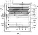
- FIG. 2 is a top view schematically showing the electrostatic actuator 100 shown in FIG.
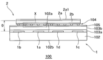
- FIG. 3 is a cross-sectional view showing an example of a cross section of the electrostatic actuator 100 along the line AA in FIG.
- FIG. 4 is a cross-sectional view showing an example of an enlarged region including the sliding structure 104 surrounded by the region X shown in FIG.
- FIG. 5 is a cross-sectional view illustrating another example in which a region including the sliding structure 104 surrounded by the region X illustrated in FIG. 3 is enlarged.
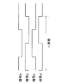
- FIG. 6 is a waveform diagram showing an example of the waveforms of the signals a to d applied to the linear electrodes 1a to 1d.
- FIG. 1 is a perspective view showing an example of the configuration of an electrostatic actuator 100 according to the present invention.
- FIG. 2 is a top view schematically showing the electrostatic actuator 100 shown in FIG.
- FIG. 3 is a cross-sectional view showing an example of a cross section of the electrostatic actuator 100 along the line AA in FIG.
- the electrostatic actuator 100 is provided independently on the substrate 102 having one surface 102a and the other surface 102b, and on one surface 102a of the substrate 102, and is arranged in parallel with each other at equal intervals. Further, a stator 1 having a plurality of linear electrodes 1a to 1d, and a movable element 2 movably disposed on the linear electrodes 1a to 1d of the stator 1 are provided.
- signals a to d for driving the movable element 2 are input to the electrostatic actuator 100 from a drive circuit (not shown). At this time, the signals a to d are respectively applied to the linear electrodes 1a to 1d via the bus lines 101a to 101d, the through-hole wirings 1b2, 1d2, and the pad electrodes 1b1, 1d1.
- the stator 1 includes the substrate 102 and the plurality of linear electrodes 1a to 1d having conductivity provided on one surface 102a of the substrate 102.
- first bus line 101a and the second bus line 101b to be connected are provided in parallel to each other.
- the plurality of linear electrodes 1a to 1d extends in a direction orthogonal to the plurality of linear electrodes 1a to 1d and is connected to the linear electrodes 1c and 1d, respectively.
- the third bus line 101c and the fourth bus line 101d are provided in parallel to each other.
- an adhesive layer 103 a and a cover film 103 b are provided so as to cover the plurality of linear electrodes 1 a to 1 d provided on the one surface 102 a of the substrate 102, and a lubricating layer 105 is provided so as to cover the cover film 103. That is, the cover film 103b is provided on the adhesive layer 103a. The lubricating layer 105 is provided on the cover film 103b.
- the substrate 102 has a thickness of, for example, 25 ⁇ m.
- the material used for the substrate 102 include polyimide, glass epoxy resin, phenol resin, PET (polyethylene terephthalate), PET-G (terephthalic acid-cyclohexanedimethanol-ethylene glycol copolymer), PEN (polyethylene naphthalate).
- polystyrene System polystyrene System
- polyacrylate polyethylene, polyurethane, etc.
- polyimide and PEN are preferable because of their high heat resistance and high strength.
- the plurality of linear electrodes 1a to 1d are provided independently on the one surface 102a of the substrate 102, and are repeatedly arranged in parallel with each other at equal intervals in a comb shape.
- the linear electrodes 1a to 1d have, for example, a wiring pitch set to 0.3 mm or less, and the linear electrodes 1a to 1d use Cu as an electrode material on a polyimide substrate, for example.
- the thickness is about 1,500 mm (see FIGS. 2 and 3).
- the two first and second bus lines 101a and 101b each have a strip shape and are provided on one side (left side in FIG. 2) of the linear electrodes 1a to 1d as described above.
- the two third and fourth bus lines 101c and 101d each have a strip shape, and are provided on the other side (right side in FIG. 2) of the linear electrodes 1a to 1d as described above.
- the adhesive layer 103a is provided on the substrate 102 so as to cover the plurality of linear electrodes 1a to 1d.
- the cover film 103b is provided on the adhesive layer 103a.
- a material used for the cover film 103 for example, polyimide is selected.
- the lubricating layer 105 is provided on the cover film 103b. That is, the lubricating layer 105 is formed on the surface of the stator 1 that faces a large number of protruding bodies 104b.
- the lubricating layer 105 is made of, for example, a silicone resin.
- the surface of the stator 1 facing the many protrusions 104b is subjected to water repellent treatment.
- a silicone resin is applied. That is, the surface of the lubricating layer 105 facing the many protrusions 104b has water repellency. As a result, water droplets are eliminated from the surface of the stator 1 facing the large number of protrusions 104b.
- the surface of the substrate 102 facing the large number of protrusions 104b is subjected to water repellent treatment.
- paraffin wax may be applied. This eliminates water droplets on the surface of the substrate 102.
- the surface of the cover film 103b facing the many protrusions 104b is subjected to water repellent treatment.
- a silicone resin may be applied. This eliminates water droplets on the surface of the cover film 103b.
- FIG. 4 is a cross-sectional view showing an example of an enlarged region including the sliding structure 104 surrounded by the region X shown in FIG.
- the movable element 2 is arranged on the surface having the electrodes of the stator 1 (a plurality of linear electrodes 1a to 1d).
- the movable element 2 includes an insulating base (resin substrate) 2a, a resistance layer (resistor film) 2b provided on the stator 1 side of the resin substrate 2a, and the resistance. And a sliding structure 104 including a large number of protruding bodies 104b provided on the stator 1 side of the layer 2b (that is, the stator side of the resin substrate 2a).
- a second water repellent agent is applied to the surface 2a1 of the mover 2 that does not face the stator 1 of the resin substrate 2a so as to cover the pattern.
- the second water repellent is, for example, any one of PTFE, a fluororesin derivative, a surfactant, a wax, dimesylloxane, a paraffinic solvent, or an emulsifier.
- Examples of the material used for the resin substrate 2a include PET (polyethylene terephthalate), PET-G (terephthalic acid-cyclohexanedimethanol-ethylene glycol copolymer), PEN (polyethylene naphthalate), PP (polypropylene), PE (polyethylene), PC (polycarbonate), PA (polyamide), PPS (polyphenylene sulfide), polyvinyl chloride, vinyl chloride-vinyl acetate copolymer, cellulose diacetate, cellulose triacetate, polystyrene, ABS, polyacrylic acid Esters, polyethylene, polyurethane, etc. are selected.
- PET polyethylene terephthalate
- PET-G terephthalic acid-cyclohexanedimethanol-ethylene glycol copolymer
- PEN polyethylene naphthalate
- PP polypropylene
- PE polyethylene
- PC polycarbonate
- PA polyamide
- PPS polyphenylene sulf
- the surface 2a1 of the resin substrate 2a of the mover 2 that does not face the stator 1 is subjected to water repellent treatment. Thereby, the moisture resistance of the mover 2 can be improved.
- the resistance layer 2b is provided on the resin substrate 2a, and the resistance layer 2b has a thickness of about 1 ⁇ m, for example.
- the resistance layer 2b has a surface resistance value in the range of 10 11 to 10 13 ⁇ / ⁇ , for example.
- the resistance layer 2b is made of, for example, antimony-doped tin oxide (ATO).
- ATO antimony-doped tin oxide
- the surface of the movable element 2 on the stator 1 side can be made to have a slippery mat-like shape, and the surface of the movable element 2 on the stator 1 side can have appropriate discharge characteristics.
- the moisture-proof resin 104c described above is a water-based resin (for example, styrene acrylic resin) that does not contain a solvent. Thereby, damage to ATO can be reduced.
- a first water repellent is mixed in the moisture-proof resin 104c.
- the first water repellent is, for example, paraffin wax. Thereby, it can suppress that the film
- the sliding structure 104 includes a large number of protrusions 104b composed of the moisture-proof resin 104c and the carbon beads 104a, and is slidable with respect to the upper surface (the lubricating layer 105) of the stator 1.
- a sliding structure 104 provided with a large number of protruding bodies 104b is formed in order to improve the slidability of the movable element 2.
- a lubricating layer 105 is formed on the surface of the stator 1 facing the sliding structure 104.
- the contact area between the stator 1 and the mover 2 is reduced, and the frictional resistance can be reduced.
- the area of the sliding structure can be reduced compared to the conventional case where the sliding structure is formed on the stator 1.
- the sliding structure 104 provided with a large number of protrusions 104b, it is necessary to form the protrusions 104b uniformly, and in order to improve the yield of the uniformity of the protrusions 104b, manufacturing is performed. Cost increases.
- the sliding structure 104 is formed on the movable element 2, and the area of the sliding structure 104 can be reduced. That is, the manufacturing cost of the electrostatic actuator 100 can be reduced by reducing the area of the sliding structure that requires special processing control.
- FIG. 5 is a cross-sectional view showing another example in which a region including the sliding structure 104 surrounded by the region X shown in FIG. 3 is enlarged.
- the sliding structure 104 includes a large number of protrusions 104b including an adhesive 104c1, a water repellent 104c2, and carbon beads 104a, and the upper surface of the stator 1 (lubricating layer 105). Slidability.
- the carbon beads 104a are bonded to the stator side of the resistance layer 2b by the adhesive 104c1, and the water repellent 104c2 is applied so as to cover the adhesive 104c1 and the carbon beads 104a.
- a sliding structure 104 provided with a large number of projecting bodies 104b is formed in order to improve the slidability of the movable element 2.
- a lubricating layer 105 is formed on the surface of the stator 1 facing the sliding structure 104.
- the contact area between the stator 1 and the mover 2 is reduced, and the frictional resistance can be reduced.
- the distance between the resistance layer 2b and the linear electrodes 1a to 1d does not change, so that the driving force of the mover 2 can be prevented from being reduced.
- the resistance layer 2b is covered with the resin substrate 2a even in the case of printing a pattern on the movable element 2, so that the degree of freedom in selecting a printing method and an ink material is increased. That is, it is possible to improve the degree of freedom of printing while improving the driving force of the moving element.
- the sliding structure 104 provided with a large number of protruding bodies 104b is formed in order to improve the slidability of the movable element 2. . Thereby, the contact area between the stator 1 and the mover 2 is reduced, and the frictional resistance can be reduced.
- the signals a to d are input to the electrostatic actuator 100 from a drive circuit (not shown). At this time, the signals a to d are respectively applied to the linear electrodes 1a to 1d via the bus lines 101a to 101d, the through-hole wirings 1b2, 1d2, and the pad electrodes 1b1, 1d1.
- FIG. 6 is a waveform diagram showing an example of the waveforms of the signals a to d applied to the linear electrodes 1a to 1d.
- FIG. 6 shows the case where the signals a to d are rectangular waves, but the same phase relationship is obtained when the signals a to d are sine waves.
- the two signals a and b inputted to the adjacent linear electrodes 1a and 1b are shifted by a quarter cycle.
- the two signals b and c input to the adjacent linear electrodes 1b and 1c are shifted by a quarter period.
- the two signals c and d input to the adjacent linear electrodes 1c and 1d are shifted by a quarter period.
- signals a and c whose phases are shifted by a half cycle are input to the linear electrode 1a and the linear electrode 1c, respectively.
- signals b and d whose phases are shifted by a half cycle are input to the linear electrode 1b and the linear electrode 1d, respectively.
- the resistance layer 2b of the movable element 2 is charged according to the signals a to d applied to the linear electrodes 1a to 1d.
- the movable element 2 moves on the stator 1 in the direction Y perpendicular to the linear electrodes 1a to 1d before the charged portion of the movable element 2 is discharged. (FIG. 2).
- the mover includes the resin substrate, the resistance layer provided on the stator side of the resin substrate, and a number of protrusions provided on the stator side of the resistance layer. And a lubricating layer is formed on a surface of the stator that faces a large number of protruding bodies. Further, the surface of the stator facing a large number of protrusions is subjected to water repellent treatment.
- the resistance layer 2b of the mover 2 is in contact with the stator via the sliding structure (mat layer) 104, so that the occurrence of wear and deterioration can be reduced.
- stator 1 and the mover 2 are difficult to stick, and the mover 2 is easy to move.
- a gap is formed between the lubricating layer 105 and the sliding structure 104, so that it is possible to suppress the stator 1 and the mover 2 from sticking to each other due to moisture.
- the projecting body 104b is conductive and discharged, so that it is difficult to be charged (overall charge), the stator and the mover are not easily stuck, and the mover is easy to move. .
- the electrostatic actuator according to the present embodiment it is possible to suppress a decrease in the driving force of the moving element when water droplets such as in high humidity or condensation are present.
Landscapes
- Micromachines (AREA)
Abstract
高湿中や結露などの水滴が存在する場合において移動子の駆動力の低下を抑制することが可能な静電アクチュエータを提供する。静電アクチュエータ(100)は、基板(102)と、基板上に設けられた電極(1a-1d)とを有する固定子(1)と、固定子の前記電極を有する面上に配置される移動子(2)と、を備える。移動子は、樹脂基板(2a)と、樹脂基板の固定子側に設けられた多数の突状体(104)と、を有する。多数の突状体に対向する固定子の面は、撥水処理されている。
Description
本発明は、静電アクチュエータに関する。
従来、電極が設けられた固定子と、この固定子上に配置されるとともに、樹脂基板と、樹脂基板上に設けられた抵抗層とを有する移動子と、を備えた静電アクチュエータが知られている(例えば、特開平1-101797号公報参照。)。
このような静電アクチュエータは、固定子と移動子が平面的に張り付いた状態で動くため、そのままでは固定子と移動子の摩擦抵抗が大きくなる傾向がある。
そこで、従来の静電アクチュエータには、固定子の上面に絶縁性バインダによって固着された導電性ビーズを固定した凹凸面を設け、この凹凸面に対向する移動子の裏面に潤滑面を設けたものがある(例えば、特開平9-121562号公報参照。)。
しかし、ビーズを含むインク(塗料)の印刷またはコーティングは、目詰まりし易く、また、ビーズ含有液体は凝集し、凹凸面にムラが出やすくなる。
そして、ビーズ含有量が少ない場合、凸部間隔が広くなり、フィルムのたわみにより、凹凸面と潤滑面が平面で接する面積が広くなる。一方、ビーズ含有量が多い場合、カールし易くまた接触する凸部が多くなり摩擦抵抗も大きくなる。
さらに、ビーズを固定する絶縁性バインダ(樹脂層)は、所定値よりも薄い場合、ビーズが脱落し易くなり、所定値よりも厚い場合、ビーズが覆われ凹凸面の所定の凹凸が形成されない。
すなわち、上記従来の静電アクチュエータでは、導電性ビーズを用いた凹凸面の面内における凹凸の均一性が低く、固定子と移動子との間の摩擦抵抗が局所的に大きくなる。
そして、既述のように、このような従来の静電アクチュエータにおいて、移動子の抵抗層は、樹脂基板を挟んで固定子と反対側に配置されている。
これにより、抵抗層が固定子と擦れて磨耗や劣化が生じるのを防ぐことができる。
しかし、この従来の静電アクチュエータでは、湿度の高い環境下で使用すると、外気に触れる面では水膜が生じその水膜が電気的遮蔽層となり移動子が駆動しにくくなる。また、結露した場合には水滴が表面に留まり、固定子と移動子との間に入り込み、固定子と移動子とが密着し摩擦が大きくなり移動子が動き難くなるという問題があった。
しかし、この従来の静電アクチュエータでは、移動子の樹脂基板の厚みが厚くなると固定子の帯状電極との電極間距離が大きくなり移動子の駆動力が弱くなる問題がある。さらに、移動子に絵柄を印刷する用途の場合に抵抗層の特性に影響を与えることが少ない印刷方式やインク材料を選ばなければならず、自由度が狭くなる問題がある。
本発明は、このような点を考慮してなされるものであり、高湿中や結露などの水滴が存在する場合において移動子の駆動力の低下を抑制することが可能な静電アクチュエータを提供することを目的とする。
本発明の一態様に係る静電アクチュエータは、
基板と、前記基板上に設けられた電極とを有する固定子と、前記固定子の前記電極を有する面上に配置される移動子と、を備えた静電アクチュエータにおいて、
前記移動子は、樹脂基板と、前記樹脂基板の固定子側に設けられた多数の突状体と、を有し、
前記多数の突状体に対向する前記固定子の面は、撥水処理されていることを特徴とする。
基板と、前記基板上に設けられた電極とを有する固定子と、前記固定子の前記電極を有する面上に配置される移動子と、を備えた静電アクチュエータにおいて、
前記移動子は、樹脂基板と、前記樹脂基板の固定子側に設けられた多数の突状体と、を有し、
前記多数の突状体に対向する前記固定子の面は、撥水処理されていることを特徴とする。
また、前記静電アクチュエータにおいて、
前記固定子は、前記基板上に設けられた前記電極を覆う接着層と、前記接着層上に設けられたカバーフィルムと、前記カバーフィルム上に設けられた潤滑層と、をさらに備え、 前記多数の突状体に対向する前記潤滑層の面は、撥水性を有するようにしてもよい。
前記固定子は、前記基板上に設けられた前記電極を覆う接着層と、前記接着層上に設けられたカバーフィルムと、前記カバーフィルム上に設けられた潤滑層と、をさらに備え、 前記多数の突状体に対向する前記潤滑層の面は、撥水性を有するようにしてもよい。
また、前記静電アクチュエータにおいて、
前記多数の突状体に対向する前記基板の面は、撥水処理されているようにしてもよい。
前記多数の突状体に対向する前記基板の面は、撥水処理されているようにしてもよい。
また、前記静電アクチュエータにおいて、
前記多数の突状体に対向する前記カバーフィルムの面は、撥水処理されているようにしてもよい。
前記多数の突状体に対向する前記カバーフィルムの面は、撥水処理されているようにしてもよい。
また、前記静電アクチュエータにおいて、
前記固定子と対向しない前記移動子の前記樹脂基板の面は、撥水処理されているようにしてもよい。
前記固定子と対向しない前記移動子の前記樹脂基板の面は、撥水処理されているようにしてもよい。
また、前記静電アクチュエータにおいて、
前記移動子は、前記樹脂基板の固定子側に設けられた抵抗層をさらに有し、
前記多数の突状体は、前記抵抗層の固定子側に設けられているようにしてもよい。
前記移動子は、前記樹脂基板の固定子側に設けられた抵抗層をさらに有し、
前記多数の突状体は、前記抵抗層の固定子側に設けられているようにしてもよい。
また、前記静電アクチュエータにおいて、
前記抵抗層は、アンチモンドープ酸化スズ(ATO)で構成されているようにしてもよい。
前記抵抗層は、アンチモンドープ酸化スズ(ATO)で構成されているようにしてもよい。
また、前記静電アクチュエータにおいて、
前記抵抗層の固定子側に設けられた前記多数の突状体は、前記抵抗層の固定子側にカーボンビーズが混ぜられた防湿性樹脂であるようにしてもよい。
前記抵抗層の固定子側に設けられた前記多数の突状体は、前記抵抗層の固定子側にカーボンビーズが混ぜられた防湿性樹脂であるようにしてもよい。
また、前記静電アクチュエータにおいて、
前記移動子の前記樹脂基板の前記固定子と対向しない面に、絵柄が記載されているようにしてもよい。
前記移動子の前記樹脂基板の前記固定子と対向しない面に、絵柄が記載されているようにしてもよい。
本発明に係る静電アクチュエータにおいて、移動子は、樹脂基板と、樹脂基板の固定子側に設けられた抵抗層と、抵抗層の固定子側に設けられた多数の突状体と、を有し、固定子の多数の突状体に対向する面に、潤滑層が形成されている。
本発明に係る静電アクチュエータによれば、湿度の高い環境下での使用であっても、移動子の駆動力が低下することを抑制でき、結露した場合であっても水滴が排除され駆動力の低下が抑制できる。
以下、本発明による静電アクチュエータの実施の形態について図面に基づいて説明する。
図1は、本発明による静電アクチュエータ100の構成の一例を示す斜視図である。また、図2は、図1に示す静電アクチュエータ100を模式的に示す上面図である。また、図3は、図2のA-A線に沿った静電アクチュエータ100の断面の一例を示す断面図である。
図1は、本発明による静電アクチュエータ100の構成の一例を示す斜視図である。また、図2は、図1に示す静電アクチュエータ100を模式的に示す上面図である。また、図3は、図2のA-A線に沿った静電アクチュエータ100の断面の一例を示す断面図である。
なお、簡単のため、図2おいては、接着層103a、カバーフィルム103b、摺動構造体104を省略している。
図1ないし図3に示すように、静電アクチュエータ100は、一面102aと他面102bとを有する基板102と、基板102の一面102aに各々独立して設けられ、互いに平行に等間隔で配置された複数の線状電極1a~1dと、を有する固定子1と、固定子1の線状電極1a~1d上に移動自在に配置された移動子2と、を備える。
なお、移動子2を駆動するための信号a~dは、図示しない駆動回路から静電アクチュエータ100に入力される。このとき、各信号a~dは、バスライン101a~101d、スルーホール配線1b2、1d2、および、パッド電極1b1、1d1を介して、線状電極1a~1dに、それぞれ印加される。
以下、固定子1について、さらに詳述する。上述のように、固定子1は、基板102と、この基板102の一面102aに設けられた導電性を有する複数の線状電極1a~1dとを備えている。
さらに、複数の線状電極1a~1dの一側に(図2の左側)、複数の線状電極1a~1dに直交する方向に延設するとともに、線状電極1aと線状電極1bに各々接続される第1のバスライン101aと第2のバスライン101bが互いに平行に設けられている。
さらに、複数の線状電極1a~1dの他側に(図2の右側)、複数の線状電極1a~1dに直交する方向に延設するとともに線状電極1cと線状電極1dに各々接続される第3のバスライン101cと第4のバスライン101dとが互いに平行に設けられている。
また、基板102の一面102a上に設けられた複数の線状電極1a~1dを覆って接着層103a、カバーフィルム103bが設けられ、さらにカバーフィルム103を覆って潤滑層105が設けられている。すなわち、カバーフィルム103bは、接着層103a上に設けられている。また、潤滑層105は、カバーフィルム103b上に設けられている。
ところで、基板102は、例えば、25μmの厚さを有する。この基板102に用いられる素材としては、例えば、ポリイミド、ガラスエポキシ樹脂、フェノール樹脂、PET(ポリエチレンテレフタレート)、PET-G(テレフタル酸-シクロヘキサンジメタノール-エチレングリコール共重合体)、PEN(ポリエチレンナフレタート)、PP(ポリプロピレン)、PE(ポリエチレン)、PC(ポリカーボネート)、PA(ポリアミド)、PPS(ポリフェニレンサルフイド)、ポリ塩化ビニル、塩化ビニル-酢酸ビニル共重合体、セルロースジアセテート、セルローストリアセテート、ポリスチレン系、ABS、ポリアクリル酸エステル、ポリエチレン、ポリウレタン等が、選択される。特にポリイミドやPENは高耐熱性、高強度であり好ましい。
また、上述のように、複数の線状電極1a~1dは、基板102の一面102a上に各々独立して設けられ、互いに平行に等間隔で櫛歯状に繰り返し配置されている。この線状電極1a~1dは、例えば、配線ピッチが0.3mm以下に設定され、また、この線状電極1a~1dは、その厚さは、例えばポリイミド基板上に電極材としてCuを使用する場合は18μm程度、電極材としてITO(酸化インジウムスズ)を形成する場合では1,500Å程度を有する(図2および図3参照)。
また、2本の第1、第2のバスライン101a、101bは、各々帯状をなし、上述のように線状電極1a~1dの一側(図2の左側)に、設けられている。
また、2本の第3、第4のバスライン101c、101dは、各々帯状をなし、上述のように線状電極1a~1dの他側(図2の右側)に、設けられている。
次に、図3により、固定子1の接着層103a、カバーフィルム103b、および潤滑層105について詳述する。
図3に示すように、接着層103aは、基板102上に複数の線状電極1a~1dを覆うように設けられている。
図3に示すように、接着層103aは、基板102上に複数の線状電極1a~1dを覆うように設けられている。
また、カバーフィルム103bは、接着層103a上に設けられている。このカバーフィルム103に用いられる素材としては、例えば、ポリイミドが選択される。
また、潤滑層105は、カバーフィルム103b上に設けられている。すなわち、多数の突状体104bに対向する固定子1の面に、潤滑層105を形成されている。この潤滑層105は、例えば、シリコーン樹脂からなる。
そして、多数の突状体104bに対向する固定子1の面は、撥水処理されている。例えば、シリコーン樹脂が塗布されている。すなわち、多数の突状体104bに対向する潤滑層105の面は、撥水性を有する。これにより、多数の突状体104bに対向する固定子1の面において、水滴が排除される。
これにより、多数の突状体104bに対向する固定子1の面において、電気的遮蔽層となる水膜の発生を防ぐことができる。
したがって、湿度の高い環境下での使用であっても、移動子2の駆動力が低下することを抑制でき、結露した場合であっても水滴が排除され駆動力の低下が抑制できる。
また、多数の突状体104bに対向する基板102の面は、撥水処理されている。例えば、パラフィンワックスが塗布されているようにしてもよい。これにより、基板102の面において、水滴が排除される。さらに、多数の突状体104bに対向するカバーフィルム103bの面は、撥水処理されている。例えば、シリコーン樹脂が塗布されているようにしてもよい。これにより、カバーフィルム103bの面において、水滴が排除される。
次に、移動子2について詳述する。ここで、図4は、図3に示す領域Xに囲まれる摺動構造体104を含む領域を拡大した一例を示す断面図である。
図1および図2に示すように、移動子2は、固定子1の電極(複数の線状電極1a~1d)を有する面上に配置されている。
この移動子2は、図3、図4に示すように、絶縁基材(樹脂基板)2aと、樹脂基板2aの固定子1側に設けられた抵抗層(抵抗体膜)2bと、この抵抗層2bの固定子1側(すなわち、樹脂基板2aの固定子側)に設けられた多数の突状体104bを含む摺動構造体104と、を有する。
そして、移動子2の樹脂基板2aの固定子1と対向しない面2a1には、絵柄が記載されている。
さらに、移動子2の樹脂基板2aの固定子1と対向しない面2a1に、該絵柄を被覆するように第2の撥水剤が塗布されている。なお、この第2の撥水剤は、例えば、PTFE、フッ素樹脂誘導体、界面活性剤、ワックス、ジメシルロキサン、パラフィン系溶剤、または、乳化剤の何れかである。
また、樹脂基板2aに用いられる素材としては、例えば、PET(ポリエチレンテレフタレート)、PET-G(テレフタル酸-シクロヘキサンジメタノール-エチレングリコール共重合体)、PEN(ポリエチレンナフレタート)、PP(ポリプロピレン)、PE(ポリエチレン)、PC(ポリカーボネート)、PA(ポリアミド)、PPS(ポリフェニレンサルフイド)、ポリ塩化ビニル、塩化ビニル-酢酸ビニル共重合体、セルロースジアセテート、セルローストリアセテート、ポリスチレン系、ABS、ポリアクリル酸エステル、ポリエチレン、ポリウレタン等が、選択される。特に、PETは安価であり、またPENは高耐熱性、高強度であり好ましい。
また、固定子1と対向しない移動子2の樹脂基板2aの面2a1は、撥水処理されている。これにより、移動子2の耐湿性を向上することができる。
抵抗層2bは、上述のように、樹脂基板2a上に設けられ、この抵抗層2bは、例えば、1μm程度の厚さを有する。また、抵抗層2bは、例えば、1011~1013Ω/□の範囲の表面抵抗値を有する。
この抵抗層2bは、例えば、アンチモンドープ酸化スズ(ATO)で構成されている。
ここで、抵抗層2bの固定子1側にカーボンビーズ(導電性ビーズ)104aが混ぜられた防湿性樹脂104cが塗布されることにより、多数の突状体104bが抵抗層2bの固定子1側に設けられる。
これにより、移動子2の固定子1側の面を滑りやすいマット状の形状にしつつ、移動子2の固定子1側の面に適度な放電特性を持たせることができる。
なお、既述の防湿性樹脂104cは、溶剤を含まない水系の樹脂(例えば、スチレンアクリル樹脂である)である。これにより、ATOへのダメージを低減することができる。
さらに、この防湿性樹脂104cには、第1の撥水剤が混ぜられている。なお、この第1の撥水剤は、例えば、パラフィンワックスである。これにより、電極と帯電面との間に、導電膜になる水の膜が形成されるのを抑制することができる。
既述のように、摺動構造体104は、防湿性樹脂104cとカーボンビーズ104aで構成される多数の突状体104bを含み、固定子1の上面(潤滑層105)に対して摺動性を有する。
すなわち、移動子2の固定子1側の面には、移動子2の摺動性を高めるために、多数の突状体104bが設けられた摺動構造体104が形成されている。そして、摺動構造体104に対向する固定子1の面に、潤滑層105が形成されている。
これにより、固定子1と移動子2との間の接触面積が減少し、摩擦抵抗を低減することができる。特に、移動子2に摺動構造体104を形成することで、固定子1に摺動構造体を形成する従来の場合と比較して、摺動構造体の面積を小さくすることができる。
ここで、多数の突状体104bが設けられた摺動構造体104において、突状体104bを均一に形成する必要があり、突状体104bの均一性の歩留まりを向上させるためには、製造コストが増加する。
しかし、上述のように、静電アクチュエータ100は、移動子2に摺動構造体104が形成されており、摺動構造体104の面積を小さくできる。すなわち、特別な加工の制御が必要な摺動構造体の面積を小さくすることで、静電アクチュエータ100の製造コストを低減することができる。
ここで、多数の突状体104bが設けられた摺動構造体104において、突状体104bを均一に形成する必要があり、突状体104bの均一性の歩留まりを向上させるためには、製造コストが増加する。
しかし、上述のように、静電アクチュエータ100は、移動子2に摺動構造体104が形成されており、摺動構造体104の面積を小さくできる。すなわち、特別な加工の制御が必要な摺動構造体の面積を小さくすることで、静電アクチュエータ100の製造コストを低減することができる。
なお、カーボンビーズ104aを接着剤で抵抗層2bに固定するようにしてもよい。ここで、図5は、図3に示す領域Xに囲まれる摺動構造体104を含む領域を拡大した他の例を示す断面図である。
図5に示すように、摺動構造体104は、接着剤104c1、撥水剤104c2、およびカーボンビーズ104aで構成される多数の突状体104bを含み、固定子1の上面(潤滑層105)に対して摺動性を有する。
すなわち、抵抗層2bの固定子側にカーボンビーズ104aを接着剤104c1により接着し、接着剤104c1およびカーボンビーズ104aを被覆するように撥水剤104c2が塗布されることにより、多数の突状体104bが抵抗層2bの固定子側に設けられる。これにより、容易に多数の突状体104bが抵抗層2bの固定子側に形成することができる。
この場合も、移動子2の固定子1側の面には、移動子2の摺動性を高めるために、多数の突状体104bが設けられた摺動構造体104が形成されている。そして、摺動構造体104に対向する固定子1の面に、潤滑層105が形成されている。
これにより、固定子1と移動子2との間の接触面積が減少し、摩擦抵抗を低減することができる。特に、移動子2の樹脂基板2aの厚みが厚くなっても、抵抗層2bと線状電極1a~1dとの電極間距離は変わらないため、移動子2の駆動力が小さくなることを防げる。さらに、後述のように、移動子2に絵柄を印刷する用途の場合にも抵抗層2bが樹脂基板2aに覆われているため、印刷方式やインク材料の選定の自由度が大きくなる。すなわち、移動子の駆動力を向上しつつ、印刷の自由度を向上させることができる。
以上のように、移動子2の固定子1側の面には、移動子2の摺動性を高めるために、多数の突状体104bが設けられた摺動構造体104が形成されている。これにより、固定子1と移動子2との間の接触面積が減少し、摩擦抵抗を低減することができる。
次に、以上のような構成を有する静電アクチュエータ100の動作について説明する。
まず、図2に示すように、信号a~dは、図示しない駆動回路から静電アクチュエータ100に入力される。このとき、各信号a~dは、バスライン101a~101d、スルーホール配線1b2、1d2、および、パッド電極1b1、1d1を介して、線状電極1a~1dに、それぞれ印加される。
まず、図2に示すように、信号a~dは、図示しない駆動回路から静電アクチュエータ100に入力される。このとき、各信号a~dは、バスライン101a~101d、スルーホール配線1b2、1d2、および、パッド電極1b1、1d1を介して、線状電極1a~1dに、それぞれ印加される。
ここで、図6は、線状電極1a~1dに印加される信号a~dの波形の一例を示す波形図である。なお、図6では、信号a~dが矩形波の場合について示しているが、信号a~dが正弦波である場合も同様の位相関係になる。
図6に示すように、隣接する線状電極1a、1bに入力される2つの信号a、bは、4分の1周期だけずれている。同様に、隣接する線状電極1b、1cに入力される2つの信号b、cは、4分の1周期だけずれている。同様に、隣接する線状電極1c、1dに入力される2つの信号c、dは、4分の1周期だけずれている。
これにより、線状電極1aと線状電極1cには、各々位相が半周期ずれた信号a、cが入力される。また、線状電極1bと線状電極1dには、各々位相が半周期ずれた信号b、dが入力される。
この場合、移動子2の抵抗層2bが、線状電極1a~1dに印加される信号a~dに応じて帯電する。そして、信号a~dの電圧が変化することにより、移動子2の帯電した部分が放電する前に、移動子2が固定子1上を線状電極1a~1dに垂直な方向Yに、移動する(図2)。
ここで、既述のように、静電アクチュエータ100において、移動子は、樹脂基板と、樹脂基板の固定子側に設けられた抵抗層と、抵抗層の固定子側に設けられた多数の突状体と、を有し、固定子の多数の突状体に対向する面に、潤滑層が形成されている。さらに、多数の突状体に対向する固定子の面は、撥水処理されている。
これにより、移動子と固定子との間の水滴が排除される。すなわち、湿度の高い環境下での使用であっても、移動子の駆動力が低下することを抑制でき、結露した場合であっても水滴が排除され駆動力の低下が抑制できる。
さらに、移動子2に絵柄を印刷する用途の場合にも抵抗層2bが樹脂基板2aに覆われているため、印刷方式やインク材料の選定の自由度が大きくなる。
さらに、移動子2の抵抗層2bが摺動構造体(マット層)104を介して固定子と接触しており、磨耗や劣化の発生を低減できる。
また、固定子1と移動子2との間に空間が介在するため、固定子1と移動子2とが貼り付つきにくくなり、移動子2が動き易くなる。
また、例えば、湿度が高い場合、潤滑層105と摺動構造体104との間に隙間ができるため、水分により固定子1と移動子2とが貼り付くのを、抑制することができる。
また、長時間運転しても、突状体104bが導電性を有し放電するため、帯電(全体チャージアップ)しにくく、固定子と移動子とが貼り付きにくくなり、移動子が動き易くなる。
以上のように、本実施例に係る静電アクチュエータによれば、高湿中や結露などの水滴が存在する場合において移動子の駆動力の低下を抑制することができる。
本発明のいくつかの実施形態を説明したが、これらの実施形態は、例として提示したものであり、発明の範囲を限定することは意図していない。これら実施形態は、その他の様々な形態で実施されることが可能であり、発明の要旨を逸脱しない範囲で、種々の省略、置き換え、変更を行うことができる。これら実施形態やその変形は、発明の範囲や要旨に含まれると同様に、特許請求の範囲に記載された発明とその均等の範囲に含まれるものである。
1 固定子
1a~1d 線状電極
1b1、1d1 パッド電極
1b2、1d2 スルーホール配線
2 移動子
2a 樹脂基板
2b 抵抗層
100 静電アクチュエータ
101a 第1のバスライン
101b 第2のバスライン
101c 第3のバスライン
101d 第4のバスライン
102 基板
103a 接着層
103b カバーフィルム
104 摺動構造体
104a カーボンビーズ
104b 突状体
105 潤滑層
a~d 信号
1a~1d 線状電極
1b1、1d1 パッド電極
1b2、1d2 スルーホール配線
2 移動子
2a 樹脂基板
2b 抵抗層
100 静電アクチュエータ
101a 第1のバスライン
101b 第2のバスライン
101c 第3のバスライン
101d 第4のバスライン
102 基板
103a 接着層
103b カバーフィルム
104 摺動構造体
104a カーボンビーズ
104b 突状体
105 潤滑層
a~d 信号
Claims (17)
- 基板と、前記基板上に設けられた電極とを有する固定子と、前記固定子の前記電極を有する面上に配置される移動子と、を備えた静電アクチュエータにおいて、
前記移動子は、樹脂基板と、前記樹脂基板の固定子側に設けられた多数の突状体と、を有し、
前記多数の突状体に対向する前記固定子の面は、撥水処理されていることを特徴とする静電アクチュエータ。 - 前記固定子は、前記基板上に設けられた前記電極を覆う接着層と、前記接着層上に設けられたカバーフィルムと、前記カバーフィルム上に設けられた潤滑層と、をさらに備え、 前記多数の突状体に対向する前記潤滑層の面は、撥水性を有する
ことを特徴とする請求項1に記載の静電アクチュエータ。 - 前記多数の突状体に対向する前記基板の面は、撥水処理されている
ことを特徴とする請求項1及び2に記載の静電アクチュエータ。 - 前記多数の突状体に対向する前記カバーフィルムの面は、撥水処理されている
ことを特徴とする請求項2に記載の静電アクチュエータ。 - 前記固定子と対向しない前記移動子の前記樹脂基板の面は、撥水処理されていることを特徴とする請求項1に記載の静電アクチュエータ。
- 前記移動子は、前記樹脂基板の固定子側に設けられた抵抗層をさらに有し、
前記多数の突状体は、前記抵抗層の固定子側に設けられていることを特徴とする請求項1に記載の静電アクチュエータ。 - 前記抵抗層は、アンチモンドープ酸化スズ(ATO)で構成されていることを特徴とする請求項6に記載の静電アクチュエータ。
- 前記抵抗層の固定子側に設けられた前記多数の突状体は、前記抵抗層の固定子側にカーボンビーズが混ぜられた防湿性樹脂である
ことを特徴とする請求項6に記載の静電アクチュエータ。 - 前記抵抗層の固定子側に設けられた前記多数の突状体は、前記抵抗層の固定子側でカーボンビーズを接着する接着剤と、前記接着剤およびカーボンビーズを被覆する第1の撥水剤とを含む
ことを特徴とする請求項6に記載の静電アクチュエータ。 - 前記移動子の前記樹脂基板の前記固定子と対向しない面に、絵柄が記載されていることを特徴とする請求項1に記載の静電アクチュエータ。
- 基板と、前記基板上に設けられた電極とを有する固定子と、前記固定子の前記電極を有する面上に配置される移動子と、を備えた静電アクチュエータにおいて、
前記移動子は、樹脂基板と、前記樹脂基板の固定子側に設けられた抵抗層と、前記抵抗層の固定子側に設けられた多数の突状体と、を有し、
前記多数の突状体に対向する前記固定子の面に、潤滑層を形成したことを特徴とする静電アクチュエータ。 - 前記潤滑層は、シリコーン樹脂を含むことを特徴とする請求項11に記載の静電アクチュエータ。
- 前記抵抗層は、アンチモンドープ酸化スズ(ATO)で構成されていることを特徴とする請求項11に記載の静電アクチュエータ。
- 前記抵抗層の固定子側に設けられた前記多数の突状体は、前記抵抗層の固定子側にカーボンビーズが混ぜられた防湿性樹脂である
ことを特徴とする請求項11に記載の静電アクチュエータ。 - 前記防湿性樹脂は、溶剤を含まない水系の樹脂であることを特徴とする請求項14に記載の静電アクチュエータ。
- 前記防湿性樹脂は、スチレンアクリル樹脂であることを特徴とする請求項14に記載の静電アクチュエータ。
- 前記移動子の前記樹脂基板の前記固定子と対向しない面に、絵柄が記載されていることを特徴とする請求項11に記載の静電アクチュエータ。
Applications Claiming Priority (2)
| Application Number | Priority Date | Filing Date | Title |
|---|---|---|---|
| JP2014035957A JP6341444B2 (ja) | 2014-02-26 | 2014-02-26 | 静電アクチュエータ |
| JP2014-035957 | 2014-02-26 |
Publications (1)
| Publication Number | Publication Date |
|---|---|
| WO2015129462A1 true WO2015129462A1 (ja) | 2015-09-03 |
Family
ID=54008785
Family Applications (1)
| Application Number | Title | Priority Date | Filing Date |
|---|---|---|---|
| PCT/JP2015/053775 Ceased WO2015129462A1 (ja) | 2014-02-26 | 2015-02-12 | 静電アクチュエータ |
Country Status (2)
| Country | Link |
|---|---|
| JP (1) | JP6341444B2 (ja) |
| WO (1) | WO2015129462A1 (ja) |
Citations (5)
| Publication number | Priority date | Publication date | Assignee | Title |
|---|---|---|---|---|
| JPH05308784A (ja) * | 1992-04-28 | 1993-11-19 | Mitsubishi Kasei Corp | 静電アクチュエータ |
| JPH07255185A (ja) * | 1993-10-08 | 1995-10-03 | Dainippon Printing Co Ltd | 静電アクチュエータにおける多層電極配線板、及びその製造方法 |
| JPH09238484A (ja) * | 1996-02-29 | 1997-09-09 | Mitsubishi Chem Corp | 静電アクチュエータ |
| JP2005237651A (ja) * | 2004-02-26 | 2005-09-08 | Akio Yamamoto | ゲーム機 |
| JP2011250623A (ja) * | 2010-05-28 | 2011-12-08 | Dainippon Printing Co Ltd | 静電アクチュエータ |
-
2014
- 2014-02-26 JP JP2014035957A patent/JP6341444B2/ja not_active Expired - Fee Related
-
2015
- 2015-02-12 WO PCT/JP2015/053775 patent/WO2015129462A1/ja not_active Ceased
Patent Citations (5)
| Publication number | Priority date | Publication date | Assignee | Title |
|---|---|---|---|---|
| JPH05308784A (ja) * | 1992-04-28 | 1993-11-19 | Mitsubishi Kasei Corp | 静電アクチュエータ |
| JPH07255185A (ja) * | 1993-10-08 | 1995-10-03 | Dainippon Printing Co Ltd | 静電アクチュエータにおける多層電極配線板、及びその製造方法 |
| JPH09238484A (ja) * | 1996-02-29 | 1997-09-09 | Mitsubishi Chem Corp | 静電アクチュエータ |
| JP2005237651A (ja) * | 2004-02-26 | 2005-09-08 | Akio Yamamoto | ゲーム機 |
| JP2011250623A (ja) * | 2010-05-28 | 2011-12-08 | Dainippon Printing Co Ltd | 静電アクチュエータ |
Also Published As
| Publication number | Publication date |
|---|---|
| JP2015162938A (ja) | 2015-09-07 |
| JP6341444B2 (ja) | 2018-06-13 |
Similar Documents
| Publication | Publication Date | Title |
|---|---|---|
| JP5609271B2 (ja) | 静電アクチュエータ | |
| KR20100015836A (ko) | 전자 기기 표시창의 터치 입력 기능을 구비한 보호 패널 | |
| EP2273354A1 (en) | Conductive plate and touch panel including the same | |
| JP6251032B2 (ja) | 回路付サスペンション基板およびヘッドジンバルアッセンブリ | |
| US20130104323A1 (en) | User Interfaces and Associated Apparatus and Methods | |
| JP6341444B2 (ja) | 静電アクチュエータ | |
| TWI476671B (zh) | 觸控面板 | |
| JP6256099B2 (ja) | 静電アクチュエータ | |
| JP5409515B2 (ja) | 静電容量センサ | |
| JP5606093B2 (ja) | 入力装置 | |
| CN104461101A (zh) | 一种具有导电保护层的触控面板及其制作方法 | |
| US20200053879A1 (en) | Wiring body and wiring body assembly | |
| JP2014026496A (ja) | タッチパネル | |
| KR20150142214A (ko) | 곡면 기판과의 접착성을 개선시킨 터치 패널 | |
| JP2011249376A (ja) | フレキシブル配線基板 | |
| JP5556359B2 (ja) | 4線式静電アクチュエータおよび固定子 | |
| JP2015184365A (ja) | 表示媒体、及び表示装置 | |
| JP6549942B2 (ja) | 配線体、配線基板、及びタッチセンサ | |
| JP2009237499A (ja) | 画像表示装置 | |
| JP2009225563A (ja) | 静電アクチュエータ | |
| JP5622082B2 (ja) | 静電アクチュエータ | |
| JP2011205786A (ja) | 4線式静電アクチュエータ | |
| JP2017045629A (ja) | スイッチ | |
| JP7710535B2 (ja) | 感圧センサユニット | |
| JP2015069609A (ja) | タッチパネル |
Legal Events
| Date | Code | Title | Description |
|---|---|---|---|
| 121 | Ep: the epo has been informed by wipo that ep was designated in this application |
Ref document number: 15755869 Country of ref document: EP Kind code of ref document: A1 |
|
| DPE1 | Request for preliminary examination filed after expiration of 19th month from priority date (pct application filed from 20040101) | ||
| NENP | Non-entry into the national phase |
Ref country code: DE |
|
| 122 | Ep: pct application non-entry in european phase |
Ref document number: 15755869 Country of ref document: EP Kind code of ref document: A1 |