WO2015129292A1 - ステージ装置およびそれを用いた荷電粒子線装置 - Google Patents
ステージ装置およびそれを用いた荷電粒子線装置 Download PDFInfo
- Publication number
- WO2015129292A1 WO2015129292A1 PCT/JP2015/050200 JP2015050200W WO2015129292A1 WO 2015129292 A1 WO2015129292 A1 WO 2015129292A1 JP 2015050200 W JP2015050200 W JP 2015050200W WO 2015129292 A1 WO2015129292 A1 WO 2015129292A1
- Authority
- WO
- WIPO (PCT)
- Prior art keywords
- stage
- rail
- slide unit
- component
- charged particle
- Prior art date
- Legal status (The legal status is an assumption and is not a legal conclusion. Google has not performed a legal analysis and makes no representation as to the accuracy of the status listed.)
- Ceased
Links
Images


Classifications
-
- H—ELECTRICITY
- H01—ELECTRIC ELEMENTS
- H01J—ELECTRIC DISCHARGE TUBES OR DISCHARGE LAMPS
- H01J37/00—Discharge tubes with provision for introducing objects or material to be exposed to the discharge, e.g. for the purpose of examination or processing thereof
- H01J37/02—Details
- H01J37/20—Means for supporting or positioning the object or the material; Means for adjusting diaphragms or lenses associated with the support
-
- H—ELECTRICITY
- H02—GENERATION; CONVERSION OR DISTRIBUTION OF ELECTRIC POWER
- H02K—DYNAMO-ELECTRIC MACHINES
- H02K41/00—Propulsion systems in which a rigid body is moved along a path due to dynamo-electric interaction between the body and a magnetic field travelling along the path
- H02K41/02—Linear motors; Sectional motors
-
- H—ELECTRICITY
- H10—SEMICONDUCTOR DEVICES; ELECTRIC SOLID-STATE DEVICES NOT OTHERWISE PROVIDED FOR
- H10P—GENERIC PROCESSES OR APPARATUS FOR THE MANUFACTURE OR TREATMENT OF DEVICES COVERED BY CLASS H10
- H10P72/00—Handling or holding of wafers, substrates or devices during manufacture or treatment thereof
- H10P72/06—Apparatus for monitoring, sorting, marking, testing or measuring
- H10P72/0604—Process monitoring, e.g. flow or thickness monitoring
-
- H—ELECTRICITY
- H10—SEMICONDUCTOR DEVICES; ELECTRIC SOLID-STATE DEVICES NOT OTHERWISE PROVIDED FOR
- H10P—GENERIC PROCESSES OR APPARATUS FOR THE MANUFACTURE OR TREATMENT OF DEVICES COVERED BY CLASS H10
- H10P72/00—Handling or holding of wafers, substrates or devices during manufacture or treatment thereof
- H10P72/50—Handling or holding of wafers, substrates or devices during manufacture or treatment thereof for positioning, orientation or alignment
-
- H—ELECTRICITY
- H10—SEMICONDUCTOR DEVICES; ELECTRIC SOLID-STATE DEVICES NOT OTHERWISE PROVIDED FOR
- H10P—GENERIC PROCESSES OR APPARATUS FOR THE MANUFACTURE OR TREATMENT OF DEVICES COVERED BY CLASS H10
- H10P72/00—Handling or holding of wafers, substrates or devices during manufacture or treatment thereof
- H10P72/70—Handling or holding of wafers, substrates or devices during manufacture or treatment thereof for supporting or gripping
- H10P72/76—Handling or holding of wafers, substrates or devices during manufacture or treatment thereof for supporting or gripping using mechanical means, e.g. clamps or pinches
- H10P72/7604—Handling or holding of wafers, substrates or devices during manufacture or treatment thereof for supporting or gripping using mechanical means, e.g. clamps or pinches the wafers being placed on a susceptor, stage or support
- H10P72/7624—Handling or holding of wafers, substrates or devices during manufacture or treatment thereof for supporting or gripping using mechanical means, e.g. clamps or pinches the wafers being placed on a susceptor, stage or support characterised by the mechanical construction of the susceptor, stage or support
-
- H—ELECTRICITY
- H01—ELECTRIC ELEMENTS
- H01J—ELECTRIC DISCHARGE TUBES OR DISCHARGE LAMPS
- H01J2237/00—Discharge tubes exposing object to beam, e.g. for analysis treatment, etching, imaging
- H01J2237/20—Positioning, supporting, modifying or maintaining the physical state of objects being observed or treated
- H01J2237/2002—Controlling environment of sample
-
- H—ELECTRICITY
- H01—ELECTRIC ELEMENTS
- H01J—ELECTRIC DISCHARGE TUBES OR DISCHARGE LAMPS
- H01J2237/00—Discharge tubes exposing object to beam, e.g. for analysis treatment, etching, imaging
- H01J2237/20—Positioning, supporting, modifying or maintaining the physical state of objects being observed or treated
- H01J2237/202—Movement
- H01J2237/20221—Translation
-
- H—ELECTRICITY
- H01—ELECTRIC ELEMENTS
- H01J—ELECTRIC DISCHARGE TUBES OR DISCHARGE LAMPS
- H01J2237/00—Discharge tubes exposing object to beam, e.g. for analysis treatment, etching, imaging
- H01J2237/20—Positioning, supporting, modifying or maintaining the physical state of objects being observed or treated
- H01J2237/202—Movement
- H01J2237/20271—Temperature responsive devices
-
- H—ELECTRICITY
- H01—ELECTRIC ELEMENTS
- H01J—ELECTRIC DISCHARGE TUBES OR DISCHARGE LAMPS
- H01J2237/00—Discharge tubes exposing object to beam, e.g. for analysis treatment, etching, imaging
- H01J2237/20—Positioning, supporting, modifying or maintaining the physical state of objects being observed or treated
- H01J2237/202—Movement
- H01J2237/20278—Motorised movement
-
- H—ELECTRICITY
- H01—ELECTRIC ELEMENTS
- H01J—ELECTRIC DISCHARGE TUBES OR DISCHARGE LAMPS
- H01J2237/00—Discharge tubes exposing object to beam, e.g. for analysis treatment, etching, imaging
- H01J2237/26—Electron or ion microscopes
- H01J2237/28—Scanning microscopes
- H01J2237/2801—Details
-
- H—ELECTRICITY
- H01—ELECTRIC ELEMENTS
- H01J—ELECTRIC DISCHARGE TUBES OR DISCHARGE LAMPS
- H01J2237/00—Discharge tubes exposing object to beam, e.g. for analysis treatment, etching, imaging
- H01J2237/26—Electron or ion microscopes
- H01J2237/28—Scanning microscopes
- H01J2237/2813—Scanning microscopes characterised by the application
- H01J2237/2817—Pattern inspection
-
- H—ELECTRICITY
- H02—GENERATION; CONVERSION OR DISTRIBUTION OF ELECTRIC POWER
- H02K—DYNAMO-ELECTRIC MACHINES
- H02K16/00—Machines with more than one rotor or stator
-
- H—ELECTRICITY
- H02—GENERATION; CONVERSION OR DISTRIBUTION OF ELECTRIC POWER
- H02K—DYNAMO-ELECTRIC MACHINES
- H02K9/00—Arrangements for cooling or ventilating
- H02K9/22—Arrangements for cooling or ventilating by solid heat conducting material embedded in, or arranged in contact with, the stator or rotor, e.g. heat bridges
- H02K9/223—Heat bridges
Definitions
- the present invention relates to a stage apparatus and a charged particle beam apparatus using the stage apparatus, and more particularly to a stage apparatus and a charged particle beam apparatus suitable for suppressing the influence of heat generated by driving the stage.
- a scanning electron microscope (hereinafter referred to as a length measuring SEM) having a length measuring function is used to evaluate whether or not the shape dimension of a pattern formed on a semiconductor wafer is correct.
- a scanning electron microscope (hereinafter referred to as a length measuring SEM) having a length measuring function is used to evaluate whether or not the shape dimension of a pattern formed on a semiconductor wafer is correct.
- the length measurement SEM an electron beam is irradiated onto the wafer, the obtained secondary electron signal is subjected to image processing, and the edge of the pattern is discriminated from the change in brightness to derive the dimension.
- the semiconductor wafer is mounted on the XY stage, and the stage device moves to change the position where the electron beam is irradiated and to inspect various positions of the wafer.
- the inspection position of the wafer can be determined by measuring the position of the stage.
- Patent Document 1 a stage device that uses a linear motor causes thermal deformation due to a change in the temperature of the stage, and as a countermeasure against the deterioration in positional accuracy due to the change in the distance from the laser interferometer mirror, Means for correction are shown.
- a permanent magnet and a stator are used, and the coil is used as a mover.
- the coil is used as a mover, and the coil needs to be fixed to the stage.
- the coil is integrally connected to the stage, the heat generated by the coil is easily transmitted to the stage, leading to an increase in the temperature of the stage.
- Patent Document 1 does not disclose a means for suppressing stage deformation as described above.
- a stage apparatus aimed at effectively suppressing stage deformation due to temperature rise of the stage is proposed.
- a first table for placing a sample below, a first drive mechanism for moving the first table in a first direction, and the first table A stage device comprising a second table for placing a table and a second drive mechanism for moving the second table in a second direction, wherein the second table is the second table A rail that guides in a direction, a slide unit that moves on the rail, and a connection member that is interposed between the second table and the second drive mechanism.
- a stage device and a charged particle beam device are proposed in which an imaginary straight line extending in a first direction and a third direction orthogonal to the second direction passes.
- the connecting member is composed of two or more members having different thermal conductivities, and among the two members, a member having a relatively high thermal conductivity is the above-mentioned member.
- a stage device and a charged particle beam device arranged on the slide unit side from the table are proposed.
- a stage device comprising: a second table for placing one table; and a second drive mechanism for moving the second table in a second direction, wherein the second table is A first rail and a second rail for guiding in a second direction; a third rail for guiding the second table in the same direction as the first rail and the second rail;
- a slide unit that moves on the third rail together with the table, and a connection member interposed between the second table and the second drive mechanism, and the connection member and the slide unit include:
- Stage apparatus imaginary straight line in the third direction perpendicular to the direction is arranged to pass, and proposes a charged particle beam device including the stage device.
- FIG. 1 is a configuration diagram of a stage apparatus used in a charged particle beam apparatus (Example 1).
- 1 is a perspective view of Example 1.
- FIG. Sectional drawing which shows the thermal bypass structure of the upper stage of Example 1.
- FIG. FIG. 3 is a perspective view illustrating a bolt connection method for the first embodiment. Sectional drawing which shows the bolt connection method for Example 1.
- FIG. The figure of another section showing the bolt connection method for Example 1.
- the block diagram of the stage apparatus used for a charged particle beam apparatus (Example 2).
- FIG. The block diagram of the stage apparatus used for a charged particle beam apparatus (Example 3).
- FIG. The block diagram of the stage apparatus used for a charged particle beam apparatus Example 4).
- a stage apparatus mainly used for a charged particle beam apparatus or the like.
- a DR-SEM Defect Review-SEM
- CD-SEM Compact Review-SEM
- It is a typical example of a particle beam device.
- Such an apparatus incorporates a stage device for evaluating fine patterns and defects formed on a large sample such as a semiconductor wafer.
- the number of patterns to be measured may reach several thousand points, and it is expected that the influence of heat generated from the drive source that drives the stage becomes more prominent.
- the stage When the temperature of the stage changes, the stage is deformed due to the effect of thermal expansion, and an error occurs in the measurement of the stage position.
- the position In a system that specifies the position by distance measurement using a mirror bar and a laser interferometer, even if the accuracy is improved by performing correction when specifying the position, if the unknown error is large, the residual error after correction becomes large For this reason, it is desirable that the thermal deformation of the stage itself can be made smaller.
- the distance measurement method using a mirror bar and a laser interferometer can obtain high measurement accuracy, if the angle of the reflection surface of the mirror bar changes, the path of the laser beam to be measured changes, resulting in an error in the measurement value.
- error causes of position measurement errors due to thermal deformation of the stage There are various types of error causes of position measurement errors due to thermal deformation of the stage. Among them, the inventors have found that the thermal deformation of the stage is greatly affected by errors caused by changing the angle of the mirror bar. Was discovered through various studies. Therefore, in a stage apparatus that uses a linear motor as a drive source and uses a distance measurement using a mirror bar and a laser interferometer, it is effective to reduce the change in the angle of the mirror bar caused by thermal deformation of the stage, A structure that realizes this is required.
- a charged particle beam is irradiated to an object placed in a vacuum, the object is fixed to a stage, and the position of the object irradiated with charged particles is changed by moving the stage.
- the structure of the stage device is such that the slide unit is fixed to a table holding an object, the slide unit is moved by being restrained by a rail, and the stage is made up of two stages.
- the slide unit is connected to the parts to connect the table of the lower stage and the mover of the linear motor that drives the table after enabling the movement in the biaxial direction, and the slide unit is attached to the rail fixed to the base.
- the slide unit has a constrained structure and is projected onto a region that is perpendicular to the plane on which the stage moves. Example of a structure of placing bets will be described.
- the slide unit attached to the part connecting the lower table and the linear motor mover suppresses thermal deformation of the stage apparatus and improves the accuracy of stage position measurement.
- FIG. 1A is a cross-sectional view showing a configuration of a stage apparatus used in the charged particle beam apparatus in the first embodiment.
- FIG. 1B is a front view of the same stage apparatus, which is viewed perpendicular to the moving direction of the upper stage.
- a line indicated by an arrow in FIG. 1B indicates a cross-sectional position in FIG. 1A, and an arrow indicates a direction in the drawing.
- a charged particle beam column for irradiating the semiconductor wafer placed on the table of the stage apparatus with a beam is disposed on the vacuum chamber.
- a space in a vacuum state is maintained.
- a beam source for emitting a charged particle beam an extraction electrode for extracting the beam from the beam source, an acceleration electrode for accelerating the beam extracted from the beam source by the extraction electrode, and the beam accelerated by the acceleration electrode are focused
- a focusing lens and a scanning deflector for scanning the beam on the sample are incorporated.
- the lower stage moves in a direction perpendicular to the paper surface
- the upper stage moves in a direction parallel to the paper surface.
- the upper stage moves with the slide unit 13 attached to the table 1 and being restrained by the rail 11 fixed to the lower table 2.
- a chuck 18 is fixed to the table 1 and a wafer is placed thereon.
- a bar mirror 17 is attached to the table 1, and a laser is applied to the reflecting surface thereof to measure the position of the stage, thereby grasping the position of the wafer.
- the linear motor for driving the upper stage is composed of a coil 3 and a permanent magnet 4, and the permanent magnet 4 is used as a stator by being fixed to the lower table 2, and the coil 3 is used as a mover.
- a connecting component 7 and a thermal bypass component 9 are interposed.
- the connecting component 7 is made of a material having low thermal conductivity, and the thermal bypass component 9 is thermally conductive. Use high-rate materials. Resin or the like is suitable for the material used for the connection component 7, and aluminum alloy or copper alloy is suitable for the material used for the thermal bypass component 9.
- the thermal bypass component 9 is connected to the slide unit 15, and the slide unit 15 contacts the rail 11 fixed to the lower table 2, thereby promoting heat dissipation to the lower table. Thereby, it is possible to suppress the heat generated by the coil 3 of the linear motor from being transmitted to the table 1 and to reduce the temperature rise of the table 1. If the temperature rise of the table 1 can be reduced, the temperature rise of the chuck 18 connected thereto can be reduced, and a temperature difference between the chuck 18 and the wafer placed thereon can be prevented.
- the lower stage moves with the slide unit 14 attached to the table 2 while being restrained by the rail 12 fixed to the base 19.
- the linear motor that drives the lower stage includes a coil 5 and a permanent magnet 6.
- the permanent magnet 6 is used as a stator by being fixed to a base 19, and the coil 5 is used as a mover.
- the connecting component 8 is made of a material having low thermal conductivity, and the thermal bypass component 10 is thermally conductive. Use high-rate materials. As with the upper stage, an aluminum alloy or a copper alloy is suitable for the material used for the thermal bypass component 10. As a material used for the connection component 8, a resin or a ceramic material is suitable. Since the ceramic material generally has a small linear expansion coefficient, the use of the ceramic material also contributes to suppressing thermal deformation of the lower table. However, since the resin material generally has a lower thermal conductivity than the ceramic material, it is better to select the material according to the situation because the resin material is more suitable when heat transfer suppression is given priority.
- a slide unit 16 is connected directly to the thermal bypass component 10, and the slide unit 16 comes into contact with the rail 12 fixed to the base 19, thereby promoting heat dissipation to the base.
- the slide unit 16 is disposed immediately below the region where the connection component 8 is in contact with the table 2, thereby suppressing deformation due to thermal expansion of the table 2. Moreover, it is suppressed that the heat which the coil 5 of a linear motor emits is transmitted to the table 2, and the temperature rise of the table 2 is also reduced.
- the apparatus according to the present embodiment includes the upper and lower two-stage tables and the two drive mechanisms that move the respective tables.
- FIG. 2 shows the same apparatus as FIG. 1 in a perspective view.
- the lower table 2 is provided with a groove dug from the upper surface. This groove is not penetrated, and the lower surface is clogged with the material surface so that the rigidity in the planar direction is maintained. Further, the ribs to be left when the grooves are formed are connected in a direction perpendicular to the rails 12 of the stage, so that rigidity against bending deformation in a plane perpendicular to the rails 12 is maintained.
- FIG. 3 is a cross-sectional view of the same apparatus, showing a cross-section in a plane perpendicular to the moving direction of the upper stage and a position crossing the thermal bypass component 9.
- the thermal bypass component 9 is in contact only with the connection component 7, the coil 3, and the slide unit 15, and is not in contact with the table 1. This suppresses the heat generated by the coil 3 from being transmitted to the table 1.
- the principle that the position accuracy of the stage is improved by the structure as described above is that the heat expansion is promoted by the heat bypass structure as described above, thereby suppressing the temperature rise of the stage and causing the thermal deformation.
- the structure according to the main deformation mode of thermal deformation contributes. This will be described with reference to FIG.
- the heat generated by the linear motor must be radiated on the base side through the contact portion between the slide unit and the rail. Therefore, the heat generated by the linear motor for the upper stage and the heat for the lower stage are used. Both of the heat generation of the linear motor contribute to the temperature rise of the table 2 of the lower stage.
- the heat bypass structure for the lower stage has the effect of reducing the heat transfer to the lower table 2, the heat transferred cannot be completely eliminated as long as it is solid-connected.
- thermal expansion occurs when the stage 2 is not constrained, it will be uniform expansion as a whole, and only the size will increase and no shape change will occur. However, actually, the movement of the table 2 is restricted by the rail 12.
- the rail 12 is fixed to the base 19. If the temperature of the base 19 does not change, the base does not expand and the position of the rail 12 does not change. In a precise apparatus such as a charged particle beam apparatus, it is better to avoid the overall temperature change, and the base part forming the vacuum vessel is also kept from temperature change. If the position of the rail 12 is not changed while the stage 2 is thermally expanded, thermal stress is generated in the stage 2. Of the three rails 12 shown in FIG.
- an effective means is that the slide unit is arranged in a region where the surface where the stage 2 and the component 8 are connected is projected in the displacement direction, and the displacement is suppressed by the slide unit.
- the two rails 12 first rail and second rail
- the slide unit 14 are arranged in a direction perpendicular to the guide direction of these rails.
- the vicinity of the central portion is displaced in a third direction that is a direction (if the first direction is the X direction and the second direction is the Y direction, the third direction is the Z direction). Therefore, in order to restrict the displacement in the Z direction, it is desirable to provide a displacement restricting member at the lower center of the stage that is considered to be the largest displacement. That is, on the virtual straight line extending in the third direction, the connection member and the connection surface that connect the lower table 2 such as the component 8 and the thermal bypass component 10 and the slide unit 16 are arranged.
- the effect of restricting the displacement of the slide unit 16 in the direction other than the slide direction can be controlled by the thermal expansion of the stage. It becomes possible to apply to the regulation of displacement based on.
- the component 8 and the thermal bypass component 10 interposed between the drive source (coil 5) serving as a heat source for deforming the stage 2 and the stage 2 are each a member having a relatively low thermal conductivity, relatively heat conduction.
- the drive source (coil 5) serving as a heat source for deforming the stage 2 and the stage 2 are each a member having a relatively low thermal conductivity, relatively heat conduction.
- the principle that the deformation of the center part of the stage 2 being raised upwards leads to the improvement of the accuracy of the stage position measurement is as follows.
- the rail 11 fixed to the stage 2 is similarly deformed. Since the upper stage moves along the rail 11, the deformation of the rail 11 leads to a change in the posture of the table 1. That is, when the center portion of the rail is lifted upward, when the table 1 is on the right side of the center portion, the table 1 is in a right-down posture, and when it is on the left side of the center portion, it is in a left-down posture. Therefore, the posture changes depending on where the table 1 is.
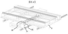
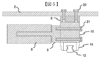
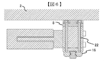
- FIGS. 4, 5, and 6 show a bolt fastening structure that is effective in attaching the connection component 8 and the thermal bypass component 10 in realizing the first embodiment.
- FIG. 4 is a perspective view showing only the lower stage, which is shown in perspective.
- FIG. 5 is a view showing a cross section of the bolt 20 for joining the lower table 2 and the connecting component 8.
- FIG. 6 is a diagram showing a cross section of the bolt 22 that joins the connecting component 8, the thermal bypass component 10 and the slide unit 16.
- the bolt 20 contacts only the lower table 2 and the connection component 8, and does not contact the thermal bypass component 10. This prevents heat from being transmitted from the thermal bypass component to the lower table 2 through the bolt 20.
- the bolt 20 is preferably made of a metal material in order to ensure strength, but metal generally has a high thermal conductivity. Even if the connection component 8 is made of a resin material or a ceramic material and the heat conduction is lowered, heat is transmitted if the metal connection is made by the bolt, so that it is effective to adopt the structure shown in FIG. However, since the connection component 8 and the thermal bypass component 10 cannot be joined only by that, the configuration shown in FIG. 6 is adopted.
- connection component 8 and the thermal bypass component 10 are joined by the bolt 22.
- the thermal bypass component 10 and the slide unit 16 are also joined by the bolt 22.
- the connection part 8 With a digging that can hold the head of the bolt 22, the bolt 22 does not need to contact the lower table 2. This prevents heat generated by the coil 5 from being transmitted to the lower table 2.
- the coil 5 and the thermal bypass component 10 are joined by a bolt 21. With these configurations, it is possible to suppress the transfer of heat to the table 2 while reliably transmitting the thrust of the mover 5 to the table 2. Further, the slide unit 16 having the two functions of releasing the heat generated in the coil 5 to the base and suppressing the thermal deformation of the table 2 can be arranged in a compact manner.
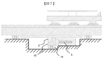
- FIG. 7 and 8 show the configuration of the stage apparatus used in the charged particle beam apparatus in the second embodiment.
- the description of the same structure as in the first embodiment is omitted, and only the different structure will be described.
- FIG. 7 is a cross-sectional view taken in the same manner as FIG. In the structure of FIG. 7, the thermal bypass component 10 'connected to the lower stage coil 5 and the component 8' connected to the lower stage 2 are different from those of the first embodiment.
- the thermal bypass component 10 'L-shaped By making the thermal bypass component 10 'L-shaped, the thickness in the left-right direction of the paper surface is reduced. Since the heat bypass component plays a role in flowing heat to the slide unit 16, it is better to use a material having high thermal conductivity. On the other hand, it is difficult to transmit heat generated by the coil 5 to the table 2. Therefore, it is effective to reduce the thickness on the upper side of the thermal bypass component 10 '.
- the component 8 ′ with low thermal conductivity compensates for this. That is, the rigidity is prevented from being lowered by the part 8 ′ filling the cut space.
- connection component 8 ′ is made of a resin material contributes to suppressing thermal deformation of the lower table 2. Since the resin material generally has a larger linear expansion coefficient than the metal material, when the lower table 2 is a metal material, the fact that the connecting component 8 ′ is a resin means that the linear expansion coefficient is larger than that of the lower table 2. . When parts having a larger linear expansion coefficient are joined to the lower surface side, the lower surface side tends to expand more, so that both ends are lifted and the central portion is lowered. On the other hand, the deformation due to the temperature rise of the lower table 2 is such a curve that the center part is lifted upward, so that both thermal stresses repel and the deformation of the center part of the lower table 2 being lifted upward is suppressed.
- joining the plate 23 made of the ceramic material to the upper surface of the lower table 2 also contributes to suppressing the deformation that is lifted to the upper side of the lower table 2.
- the ceramics plate 23 has a longer shape in a direction perpendicular to the rails 12 for the lower stage. That is, since the thermal deformation of the lower table 2 is caused by the reaction force of the rail 12, it is effective to lengthen the same direction as the reaction force in order to generate a force in a direction to cancel this. Since the ceramic material generally has a smaller linear expansion coefficient than the metal material, even if the temperature rises by the same amount as the table 2 and the ceramic plate 23, the generated elongation is smaller in the ceramic plate 23. Thereby, a force in the direction of contracting the upper surface acts on the table 2, and a force in a direction of lowering the central portion is generated. Thereby, it becomes possible to suppress the curvature of the table 2.
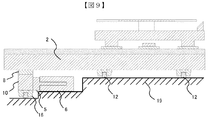
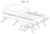
- FIGS. 9 and 10 show the configuration of the stage apparatus used in the charged particle beam apparatus according to the third embodiment.
- the position of the linear motor for the lower stage is changed from the center toward the end. If the linear motor is arranged at the end, the digging at the center of the base 19 is eliminated, which may be advantageous for the rigidity of the base 19 forming the vacuum vessel.
- the normal rail 12 for restraining the movement of the table 2 is arranged in the center, the length of the intervening parts is shortened and interposed when the deformation of the center of the table 2 being lifted upward is suppressed. Since the elongation of the parts becomes small, the effect is exhibited by suppressing the deformation of the table 2.
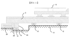
- FIG. 11 shows a configuration of a stage apparatus used for the charged particle beam apparatus in the fourth embodiment.
- the use of the moving coil type for the upper stage linear motor is the same as in the previous embodiments, except that a moving magnet type is used for the lower stage linear motor.
- the magnetic field fluctuates, which is disadvantageous in handling charged particle beams.
- the lower stage linear motor is arranged at the end. Since the charged particle beam is handled on the wafer placed on the chuck, the moving magnet 26 is separated from the moving magnet 26 in both the vertical direction and the horizontal direction so as not to have an adverse effect.
- the mover 26 becomes a magnet, and the coil 25 is fixed to the base 19.
- the heat generated by the coil 25 is transmitted directly to the base 19 and is not transmitted to the table 2. Thereby, the temperature rise of the table 2 is reduced and thermal deformation is also reduced. Since the mover 26 does not generate heat, only one component 24 is required to connect the mover 26 and the table 2. Moreover, since there is no problem of heat, the connection component 24 may be made of a metal material. However, since the stage temperature rise due to the heat generated by the linear motor for the upper stage remains, it is effective to suppress the thermal deformation of the table 2 by arranging the connecting component 24 and the slide unit 14 vertically.
- Upper table 2 Lower table 3 Upper stage linear motor coil (mover) 4 Upper stage linear motor magnet (stator) 5 Lower stage linear motor coil (mover) 6 Linear motor magnet for lower stage (stator) 7 Upper Table Connection Parts 8 Lower Table Connection Parts 9 Upper Table Thermal Bypass Parts 10 Lower Table Thermal Bypass Parts 11 Upper Stage Rails 12 Lower Stage Rails 13 Upper Stage Slide Units 14 Lower Stage Slide Units 15 Upper Stages Stage thermal bypass slide unit 16 Lower stage thermal bypass slide unit 17 Mirror bar 18 Chuck 19 Base 20 to 22 Bolt 23 Ceramic plate 24 Lower table connection component 25 Lower stage rear motor motor (stator) 26 Reanimotor magnet for lower stage (mover)
Landscapes
- Chemical & Material Sciences (AREA)
- Engineering & Computer Science (AREA)
- Analytical Chemistry (AREA)
- Physics & Mathematics (AREA)
- Combustion & Propulsion (AREA)
- Electromagnetism (AREA)
- Power Engineering (AREA)
- Container, Conveyance, Adherence, Positioning, Of Wafer (AREA)
- Electron Beam Exposure (AREA)
Abstract
本発明は、リニアモータの発熱による温度上昇で生じるステージの熱変形を効果的に抑制するステージ装置およびそれを用いた荷電粒子線装置の提供を目的とする。上記目的を達成するために、テーブル(2)とテーブルを所定の方向に駆動するリニアモータ(5、6)を備えたステージ装置であって、テーブルと前記リニアモータの可動子を部品(8、10)によって接続し、部品10にはスライドユニット(16)を取り付けてベースに固定されたレールで移動を拘束し、同時に、そのスライドユニットは部品(8)がテーブルと接合している箇所の垂直下部に配置することで、テーブルの熱変形を抑制する。
Description
本発明は、ステージ装置及びそれを用いた荷電粒子線装置に係り、特にステージを駆動することによって生ずる発熱の影響を抑制するのに好適なステージ装置及び荷電粒子線装置に関する。
近年の半導体素子の微細化に伴い、製造装置のみならず、検査や評価装置にもそれに対応した高精度化が要求されている。通常、半導体ウェハ上に形成したパターンの形状寸法が正しいか否かを評価するために、測長機能を備えた走査型電子顕微鏡(以下、測長SEMと称す)が用いられている。測長SEMでは、ウェハ上に電子線を照射し、得られた二次電子信号を画像処理し、その明暗の変化からパターンのエッジを判別して寸法を導き出している。
半導体ウェハはXYステージに装着し、ステージ装置が移動することで、電子線を照射する位置を変え、ウェハの様々な位置の検査を行うことが可能になる。ウェハの検査位置は、ステージの位置を計測することで判別可能となり、この計測精度を高める手段として、特許文献1に示されるようなミラーバーとレーザー干渉計を利用した手段などがある。
特許文献1では、リニアモータを利用したステージ装置が、ステージの温度変化により熱変形を生じ、レーザー干渉計用のミラーとの距離が変化することで位置精度が悪化することの対策として、補正により修正する手段が示されている。
XYステージの直動運動を作り出すための代表的な機構として、リニアモータを用いる機構がある。ただし、測長SEMのような荷電粒子線を扱う装置においては、真空中にステージ装置を配置しなければならない。一方、リニアモータを駆動するために、コイルに電流を流すとジュール熱が発生する。コイルが空気中に置かれている場合には、空気に熱を伝えることで放熱が可能であるが、真空中ではそれが出来ないために放熱がしにくく、温度上昇を招きやすい。また、永久磁石を可動子として使用すると、永久磁石の移動によって磁界が変化し、荷電粒子線に影響を及ぼす場合がある。磁界に関する対策としては、永久磁石と固定子とし、コイルを可動子にすることで解決するが、その場合、コイルを可動子として使用することとなり、コイルをステージに固定する必要がある。コイルがステージと一体的に接続されると、コイルの発熱がステージに伝わり易くなり、ステージの温度上昇を招くことになる。
発明者らの検討によって、このようなステージの温度上昇によってステージが変形する可能性があることが明らかになった。測長SEMのように高倍率での測定を実施する場合、ステージの僅かな変形が測定精度の低下や視野ずれの原因になる可能性がある。特許文献1には、上述のようなステージ変形を抑制する手段についての開示がない。以下、ステージの温度上昇に基づくステージ変形を効果的に抑制することを目的とするステージ装置を提案する。
上記目的を達成するための一態様として、以下に試料を載置するための第1のテーブルと、当該第1のテーブルを第1の方向に移動させる第1の駆動機構と、前記第1のテーブルを載置するための第2のテーブルと、当該第2のテーブルを第2の方向に移動させる第2の駆動機構を備えたステージ装置であって、前記第2のテーブルを前記第2の方向に案内するレールと、当該レール上を移動するスライドユニットと、前記第2のテーブルと前記第2の駆動機構間に介在する接続部材とを備え、当該接続部材と前記スライドユニットは、前記第1の方向及び前記第2の方向に直交する第3の方向に延びる仮想直線が通過するように配列されるステージ装置、及び荷電粒子線装置を提案する。
更に、上記目的を達成するための他の態様として、上記接続部材は、熱伝導率の異なる2以上の部材によって構成され、当該2つの部材の内、相対的に熱伝導率の高い部材が前記テーブルより前記スライドユニット側に配置されるステージ装置、及び荷電粒子線装置を提案する。
また、上記目的を達成するための更に他の態様として、試料を載置するための第1のテーブルと、当該第1のテーブルを第1の方向に移動させる第1の駆動機構と、前記第1のテーブルを載置するための第2のテーブルと、当該第2のテーブルを第2の方向に移動させる第2の駆動機構を備えたステージ装置であって、前記第2のテーブルを、前記第2の方向に案内する第1のレール及び第2のレールと、当該第1のレールと前記第2のレールと同じ方向に前記第2のテーブルを案内する第3のレールと、前記第2のテーブルと共に前記第3のレール上を移動するスライドユニットと、前記第2のテーブルと前記前記第2の駆動機構との間に介在する接続部材とを備え、当該接続部材と前記スライドユニットは、前記第1の方向及び前記第2の方向に直交する第3の方向の仮想直線が通過するように配列されるステージ装置、及び当該ステージ装置を備えた荷電粒子線装置を提案する。
上記構成によれば、ステージの温度情報に基づく変形を効果的に抑制することが可能となる。
以下に説明する実施例は、主に荷電粒子線装置等に用いられるステージ装置に関するものである。例えば、半導体デバイスの出来栄えを評価するために用いられるCD-SEMや上位の欠陥検査装置にて得られた欠陥の座標情報に基づいて、欠陥をレビューするDR-SEM(Defect Review-SEM)は荷電粒子線装置の代表例である。このような装置には、半導体ウェハのような大型の試料上に形成された微細なパターンや欠陥を評価するためのステージ装置が内蔵されている。特に昨今のCD-SEMでは、測定対象パターンが数千点に及ぶこともあり、ステージを駆動する駆動源から発生する熱の影響がより顕著になることが予想される。ステージの温度が変化すると、熱膨張の影響でステージの変形が生じ、ステージ位置の計測に誤差が生じる。ミラーバーとレーザー干渉計を利用した距離計測によって位置を特定するシステムにおいて、位置を特定する際に補正を施すことで精度を上げるとしても、未知の誤差が大きければ、補正後の残留誤差が大きくなることから、ステージの熱変形そのものをより小さくできることが望ましい。
ミラーバーとレーザー干渉計を利用した距離計測方法は、高い計測精度を得られるものの、ミラーバーの反射面の角度が変化すると、計測するレーザー光の経路が変化し、計測値に誤差が生じる。ステージの熱変形による位置計測の誤差には様々なタイプの誤差原因があるが、その中で、ステージの熱変形がミラーバーの角度を変化させることで生じている誤差の影響が大きいことを発明者は種々の検討によって発見した。よって、リニアモータを駆動源に用いるステージ装置であって、ミラーバーとレーザー干渉計を利用した距離計測を用いるシステムにおいては、ステージの熱変形によって生じるミラーバーの角度変化を小さくすることが有効であり、そのことを実現する構造が求められる。
以下に説明する実施例では、真空中に配置した対象物に荷電粒子線を照射し、その対象物をステージに固定し、ステージを移動させることで荷電粒子を照射する対象物の位置を変更する装置において、そのステージ装置の構成は、対象物を保持するテーブルにスライドユニットを固定し、そのスライドユニットがレールに拘束されて移動する構造をとり、かつ、そのステージを上下2段にすることで2軸方向への移動を可能にした上で、下段ステージのテーブルとそれを駆動するリニアモータの可動子を接続するに部品にスライドユニットを接続し、そのスライドユニットはベースに固定されたレールに拘束される構造をとり、かつ、下段テーブルと接続する箇所をステージが移動する平面に対して垂直に投影した領域にそのスライドユニットを配置する構造とする例について説明する。
上記の構成を用いることにより、下段テーブルとリニアモータ可動子を接続する部品に取り付けたスライドユニットがステージの装置の熱変形を抑制し、ステージの位置計測の精度を向上させる。
以下、図面を用いて実施例を説明する。
図1(A)は、第1の実施例における荷電粒子線装置に用いるステージ装置の構成を示した断面図である。図1(B)は同じステージ装置の正面図であり、上段ステージの移動方向に対して垂直に見ている。図1(B)の矢印が示す線が図1(A)の断面位置を示しており、矢印が図示方向を示している。
図1に例示するようなステージ装置は、走査電子顕微鏡の真空チャンバ内に内蔵される。真空チャンバ上には、ステージ装置のテーブル上に載置された半導体ウェハにビームを照射するための荷電粒子ビームカラムが配置される、荷電粒子ビームカラム内には、真空状態が保たれた空間内に、荷電粒子ビームを放出するビーム源、当該ビーム源からビームを引き出すための引出電極、引出電極によってビーム源より引き出されたビームを加速する加速電極、当該加速電極によって加速されたビームを集束する集束レンズ、及び試料上でビームを走査するための走査偏向器が内蔵される。
図1(A)において、下段ステージは紙面に垂直な方向に移動し、上段ステージは紙面に平行な方向に移動する。上段ステージはテーブル1にスライドユニット13が取り付き、下段テーブル2に固定されたレール11に拘束されてながら移動を行う。また、テーブル1にチャック18を固定し、ここにウェハを載せる。また、テーブル1にバーミラー17を取り付け、その反射面にレーザーを当てることで、ステージの位置計測を行い、それによってウェハの位置を把握する。上段ステージを駆動するリニアモータはコイル3と永久磁石4からなり、永久磁石4は下段テーブル2に固定することで固定子として用い、コイル3を可動子として使用する。上段テーブル1とリニアモータの可動子3を接続するにあたっては、接続部品7と熱バイパス部品9を介在させ、接続部品7には熱伝導率の低い材質を用い、熱バイパス部品9には熱伝導率の高い材質を用いる。接続部品7に用いる材質としては樹脂などが適しており、熱バイパス部品9に用いる材質としては、アルミ合金や銅合金が適している。熱バイパス部品9はスライドユニット15に接続し、スライドユニット15は下段テーブル2に固定されたレール11に接触することで、下段テーブルへの放熱を促進する。これによって、リニアモータのコイル3が発する熱がテーブル1に伝わるのを抑制でき、テーブル1の温度上昇を低減できる。テーブル1の温度上昇を低減できれば、それと接続しているチャック18の温度上昇も低減でき、チャック18とそれに載せるウェハとの間に温度差生じることも防止できる。
下段ステージはテーブル2にスライドユニット14が取り付き、ベース19に固定されたレール12に拘束されながら移動を行う。下段ステージを駆動するリニアモータはコイル5と永久磁石6からなり、永久磁石6はベース19に固定することで固定子として用い、コイル5を可動子として使用する。
下段テーブル2とリニアモータの可動子5を接続するにあたっては、接続部品8と熱バイパス部品10を介在させ、接続部品8には熱伝導率の低い材質を用い、熱バイパス部品10には熱伝導率の高い材質を用いる。上段ステージと同様に、熱バイパス部品10に用いる材質としては、アルミ合金や銅合金が適している。接続部品8に用いる材質としては樹脂もしくはセラミクス材が適している。セラミクス材は一般に線膨張係数が小さいことから、セラミクス材を使用することは下段テーブルの熱変形を抑制することにも貢献する。ただし、一般にセラミクス材よりも樹脂材方が熱伝導率は低いので、伝熱抑制を優先する場合は、樹脂材の方が適していることから状況に応じて材質を選択するのがよい。熱バイパス部品10には真下にスライドユニット16を接続させ、そのスライドユニット16はベース19に固定されたレール12に接触することで、ベースへの放熱を促進する。これと同時に、接続部品8がテーブル2に接触している領域の真下にスライドユニット16を配置することで、テーブル2の熱膨張による変形を抑制する。また、リニアモータのコイル5が発する熱がテーブル2に伝わるのも抑制し、テーブル2の温度上昇も低減する。以上のように本実施例装置は、上下2段のテーブルと、それぞれのテーブルを移動させる2つの駆動機構を備えている。
図2は、図1と同じ装置を斜視図によって示している。上段テーブル1に取り付けるバーミラー17は2コあり、上段ステージの移動方向と下段ステージの移動方向のそれぞれに反射面が垂直になるように設置し、それぞれの移動距離の計測に用いる。
下段テーブル2には、上側の面から掘り込んだ形の溝を設けている。この溝は貫通はさせず、下側の面は材料面が詰まっていることで、平面方向の剛性を保つようにする。また、溝を形成する際に残すリブは、ステージのレール12に対して垂直方向につながった形にすることで、レール12と垂直な面内での曲げ変形に対する剛性を保つようにする。
図3は、同じ装置の断面図であり、上段ステージの移動方向に垂直な面での断面であって、熱バイパス部品9を横切る位置での断面図を示している。熱バイパス部品9は、接続部品7、コイル3、スライドユニット15とのみ接触しており、テーブル1とは接触していない。このことによって、コイル3の発熱が、テーブル1に伝わるのを抑えている。
上述のような構造によって、ステージの位置精度が向上する原理は、上述のような熱バイパスの構造によって放熱を促進することで、ステージの温度上昇が抑制され、熱変形の原因となる熱膨張量が低減することに他に、熱変形の主要な変形モードに応じた構造としたことが寄与している。このことを図1(A)に戻って説明する。
真空容器内でXYステージを使用すると、リニアモータの発熱はスライドユニットとレールの接触部を通じてベース側で熱を流さざるを得なくなることから、上段ステージ用のリニアモータの発熱と、下段ステージ用のリニアモータの発熱の両方とも、下段ステージのテーブル2の温度上昇に寄与する。下段ステージ用の熱バイパス構造は下段テーブル2への伝熱を低減する効果はあるものの、固体接続されている以上、伝わる熱を完全になくすことは出来ない。リニアモータの発熱によってテーブル2にある程度の温度上昇が生じると、ステージの材質によって決まる線膨張係数と、温度上昇量の積で決まる熱膨張が生じる。ステージ2が拘束されていない状態で熱膨張が生じると、それは全体的に均一な膨張となり、サイズが大きくなるだけで形の変化は起きない。しかし、実際には、テーブル2はレール12によって、動きが拘束されている。レール12は、ベース19に固定しており、ベース19の温度が変化しなければ、ベースの膨張はなく、レール12の位置は変化しない。荷電粒子線装置のような精密な装置においては、全体的な温度変化を避けた方がよく、真空容器を形成するベース部分も温度変化しないように保たれる。ステージ2が熱膨張する中でレール12の位置が変わらずにいると、ステージ2には熱応力が発生する。図1(A)に示した3本のレール12のうち、中央のレールを無視して、両脇の2本のレールだけに着目した場合、ステージ2が膨張しようとすることは、スライドユニットを通じてレールを紙面の左右方向に移動させようとすることになる。実際にはレールは固定されているため移動しないことから、両脇の2本のレールはスライドユニットを中央方向に向かわせる反力が発生する。この反力は、ステージ2の下面側で発生することから、モーメント力となってステージ2に作用し、ステージ2の中央部が上に持ち上がる変形を生じさせる。すなわち、ステージ2の熱膨張を両脇のレールが拘束することは、ステージ2に曲げ応力を発生させることになる。このような応力状態にある中で、上述の説明では無視していた中央のレールが存在するようになった場合、ステージ2の中央部が上側に変位しようとする変形を抑制することに役立つ。すなわち、ステージ2と接続部品8が接合している面を垂直に下ろした領域の中に移動が拘束されたスライドユニット16が接続されていると、垂直方向の変位を抑制する。スライドユニット16は、中央のレールによって拘束されていることで、上方向には変位しにくい状態にあり、それが部品10、8を通じて、テーブル2につながっていることで、そのつながっている箇所は上方向に変位しづらくなる。このことを効率よく作用させるためには、力が作用する面に垂直に力をかけることが有効である。
そのため、ステージ2と部品8が接続している面を、変位方向に投影した領域の中にスライドユニットを配置させ、そのスライドユニットによって変位を抑制させたことが有効な手段となる。上述のように、ステージ2の端部に近い位置に設置された2つのレール12(第1のレールと第2のレール)とスライドユニット14は、これらレールの案内方向に対し垂直な方向へのステージ2の移動を規制するため、ステージ2が熱膨張すると、その変位は、上段テーブル1の移動方向である第1の方向、及び下段テーブル2の移動方向である第2の方向に対し垂直な方向である第3の方向(第1の方向がX方向、第2の方向がY方向であれば、第3の方向はZ方向)に、その中央部近傍が変位することになる。よって、そのZ方向の変位を規制するために、最も大きく変位すると考えられるステージ中央下部に変位規制部材を設けることが望ましい。即ち、第3の方向に延びる仮想直線上に、部品8や熱バイパス部品10のような下段テーブル2とスライドユニット16との間を接続する接続部材と接続面を配列させる。このように第3の仮想直線が通過するように、部品8、熱バイパス部品10、及びスライドユニット16を配列することで、スライドユニット16のスライド方向以外への変位規制効果を、ステージの熱膨張に基づく変位の規制に適用することが可能となる。
また、ステージ2を変形させる熱源となる駆動源(コイル5)とステージ2との間に介在する部品8と熱バイパス部品10を、それぞれ相対的に熱伝導率の低い部材、相対的に熱伝導率の高い部材とすることによって、ステージ側には熱が逃げにくく、ベース側には熱が逃げやすい状態にすることができる。このような構成によれば、コイル5で発生した熱をスライドユニット16、及びレール12を介して効果的に逃がすことが可能となる。
ステージ2の中央部が上側に持ち上がる変形を抑制したことが、ステージの位置計測の精度向上につながる原理は以下のことによる。ステージ2の中央部が上側に持ち上がると、ステージ2に固定したレール11も同じように変形することになる。上段ステージはレール11に沿って移動するため、レール11の変形はテーブル1の姿勢変化につながる。すなわち、レールの中央部が上に持ち上がると、その中央部よりテーブル1が右側にいる時は、テーブル1は右下がりの姿勢となり、中央部より左側にいる時は左下がりの姿勢となる。よって、テーブル1がどの位置にいるかによって姿勢が変化することとなる。テーブル1にはバーミラーを固定していることから、テーブル1の姿勢変化はバーミラーの角度変化に直結する。バーミラーは反射面の角度が変化すると距離計測に誤差が生じる。特に、ステージ1の場所によって角度の変化量が異なるため、補正のしづらい誤差であることから、本発明の構造によって、バーミラーの角度変化を抑えられるようになることが、ステージの位置計測の精度向上に大きく役立つ。第1の実施例を実現するにあたり、接続部品8、および、熱バイパス部品10を取り付けるにあたって有効なボルト締結の構造を図4、5、6に示す。
図4は下段ステージのみを表示した斜視図で、透視的に表示している。図5は下段テーブル2と接続部品8を接合するためのボルト20の断面を表示した図である。図6は接続部品8と、熱バイパス部品10およびスライドユニット16を接合するボルト22の断面を表示した図である。
図5に示すように、ボルト20は、下段テーブル2と接続部品8とのみ接触して、熱バイパス部品10には接触しないようにする。このことによって、ボルト20を通じて熱バイパス部品から下段テーブル2に熱が伝わることを防止している。ボルト20は強度を確保するために、金属材で構成するのがよいが、金属が一般に熱伝導率が高い。接続部品8を樹脂材やセラミクス材にして熱伝導を下げても、ボルトによって金属接続していると熱が伝わってしまうことから、図5のような構造をとることが有効となる。ただし、それだけでは接続部品8と熱バイパス部品10を接合することができないことから、図6に示す構成をとる。すなわち、接続部品8のボルト22の頭がおさまる座を掘り込んで作り、ボルト22によって接続部品8と熱バイパス部品10を接合する。同時に、ボルト22によって熱バイパス部品10とスライドユニット16の接合も行う。ボルト22の頭がおさまる掘り込みを接続部品8に設けることで、ボルト22は下段テーブル2とは接触しなくて済む。これによりコイル5の発熱が下段テーブル2に伝わることを防止する。また、図5に示すように、コイル5と熱バイパス部品10の接合は、ボルト21によって行う。これらの構成によって、可動子5の推力をテーブル2に確実に伝えた上で、テーブル2への熱の伝わりは抑えることが可能となる。また、コイル5の発熱をベースに逃がすことと、テーブル2の熱変形抑制を行うことの2つ機能をもったスライドユニット16を、コンパクトに配置することが可能となる。
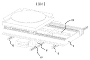
図7、図8に、第2の実施例における荷電粒子線装置に用いるステージ装置の構成を示す。第1の実施例と同じ構造の所は説明を省略し、構造が異なる所のみを説明する。
図7は図1(A)と同じとり方をした断面図である。図7の構造では、下段ステージ用のコイル5に接続する熱バイパス部品10’と、下段ステージ2に接続する部品8’が第1の実施例と異なる。熱バイパス部品10’をL字型にしたことで、紙面の左右方向の肉厚が薄くなる。熱バイパス部品は、スライドユニット16に熱を流すことを役割の一つにしているため、熱伝導率が高い材料を用いる方がよい。一方で、コイル5による発熱をテーブル2へは伝えにくくしたい。そこで、熱バイパス部品10’の上側に肉厚を薄くしたことが有効に働く。すなわち、肉厚が薄くなれば、伝熱経路の断面積が小さくなり、伝熱量を抑えるのに有効となる。肉厚が薄くなって剛性が低下することに関しては、熱伝導率が低い部品8’がそれを補っている。すなわち、削られた空間を部品8’が埋めることで剛性を低下を防いでいる。
接続部品8’を樹脂材にした上で、下段テーブル2に接合する面を広くすることは、下段テーブル2の熱変形を抑制することに貢献する。樹脂材は、一般に金属材より線膨張係数が大きいことから、下段テーブル2が金属材である場合、接続部品8’が樹脂であることは、下段テーブル2より線膨張係数が大きいことを意味する。線膨張係数がより大きい部品が下面側に接合されていることは、下面側の方がより膨張しようとして、両端が持ち上がり、中央部が下に下がるような変形を起こそうとする。一方、下段テーブル2の温上昇による変形は、中央部が上側に持ち上がるような湾曲であることから、双方の熱応力が反発し、下段テーブル2の中央部が上側に持ち上がる変形が抑制される。
また、図8に示したようにセラミクス材による板23を下段テーブル2の上面に接合することも下段テーブル2の上側に持ち上がる変形を抑制することに貢献する。その際、セラミクス板23は下段ステージ用のレール12に対して垂直な方向により長い形状とする。すなわち、下段テーブル2の熱変形はレール12の反力によって生じるものであることから、これを打ち消す方向の力を発生させるには、反力と同じ方向を長くするのが効果的である。セラミクス材は金属材よりも一般に線膨張係数が小さいことから、テーブル2と、セラミクス板23が同じだけの温度上昇が生じてもそれによって生じる伸びはセラミクス板23の方が小さい。これにより、テーブル2には上側の面を収縮させる方向の力が作用し、中央部を下に下げる方向の力が発生する。これにより、テーブル2の湾曲を抑制することが可能となる。
図9、図10に、第3の実施例における荷電粒子線装置に用いるステージ装置の構成を示す。本実施例においては、下段ステージ用のリニアモータを中央から端の方に位置を変えている。リニアモータを端に配置するとベース19の中央部での掘り込みがなくなり、真空容器を形成するベース19の剛性に対して有利なる場合がある。また、テーブル2の移動を拘束するための通常のレール12が中央に配置されることで、テーブル2の中央が上側に持ち上がる変形を抑制するあたり、介在する部品の長さが短くなり、介在する部品の伸びが小さくなることから、テーブル2の変形を抑制するのにより効果を発揮する。
図11に、第4の実施例における荷電粒子線装置に用いるステージ装置の構成を示す。本実施においては、上段ステージのリニアモータにムービングコイル式を用いることは、これまでの実施例と同じであるが、下段ステージのリニアモータにムービングマグネット式を用いる点が異なる。ムービングマグネット方式を適用すると、磁界の変動が生じ、荷電粒子線を扱う上で不利となる。このことを解決するために、下段ステージ用リニアモータは端に配置している。荷電粒子線を扱うのはチャックに載せたウェハ上であるため、移動する磁石26とは、上下方向と横方向の両方で距離を置き、悪影響を及ぼさないようにする。下段ステージのリニアモータにムービングマグネット式を用いることで、可動子26が磁石となり、コイル25がベース19に固定される。この構造により、コイル25の発熱は直接ベース19に伝わり、テーブル2に伝わることがなくなる。これによって、テーブル2の温度上昇が小さくなり、熱変形も小さくなる。また、可動子26は発熱しないため、可動子26とテーブル2を接続する部品24は1コで済む。また、熱の問題がないため、接続部品24は金属材で構成すればよい。ただし、上段ステージ用のリニアモータの発熱によるステージの温度上昇は残るため、接続部品24とスライドユニット14を垂直に配置することで、テーブル2の熱変形を抑制することが有効である。
1 上段テーブル
2 下段テーブル
3 上段ステージ用リニアモータのコイル(可動子)
4 上段ステージ用リニアモータの磁石(固定子)
5 下段ステージ用リニアモータのコイル(可動子)
6 下段ステージ用リニアモータの磁石(固定子)
7 上段テーブル接続用部品
8 下段テーブル接続用部品
9 上段テーブル用熱バイパス部品
10 下段テーブル用熱バイパス部品
11 上段ステージ用レール
12 下段ステージ用レール
13 上段ステージ用スライドユニット
14 下段ステージ用スライドユニット
15 上段ステージ熱バイパス用スライドユニット
16 下段ステージ熱バイパス用スライドユニット
17 ミラーバー
18 チャック
19 ベース
20~22 ボルト
23 セラミックス板
24 下段テーブル接続部品
25 下段ステージ用リアニモータのコイル(固定子)
26 下段ステージ用リアニモータの磁石(可動子)
2 下段テーブル
3 上段ステージ用リニアモータのコイル(可動子)
4 上段ステージ用リニアモータの磁石(固定子)
5 下段ステージ用リニアモータのコイル(可動子)
6 下段ステージ用リニアモータの磁石(固定子)
7 上段テーブル接続用部品
8 下段テーブル接続用部品
9 上段テーブル用熱バイパス部品
10 下段テーブル用熱バイパス部品
11 上段ステージ用レール
12 下段ステージ用レール
13 上段ステージ用スライドユニット
14 下段ステージ用スライドユニット
15 上段ステージ熱バイパス用スライドユニット
16 下段ステージ熱バイパス用スライドユニット
17 ミラーバー
18 チャック
19 ベース
20~22 ボルト
23 セラミックス板
24 下段テーブル接続部品
25 下段ステージ用リアニモータのコイル(固定子)
26 下段ステージ用リアニモータの磁石(可動子)
Claims (11)
- 試料を載置するための第1のテーブルと、当該第1のテーブルを第1の方向に移動させる第1の駆動機構と、前記第1のテーブルを載置するための第2のテーブルと、当該第2のテーブルを第2の方向に移動させる第2の駆動機構を備えたステージ装置において、
前記第2のテーブルを前記第2の方向に案内するレールと、当該レール上を移動するスライドユニットと、前記第2のテーブルと前記第2の駆動機構間に介在する接続部材とを備え、当該接続部材と前記スライドユニットは、前記第1の方向及び前記第2の方向に直交する第3の方向に延びる仮想直線が通過するように配列されることを特徴とするステージ装置。 - 請求項1において、
前記接続部材は、熱伝導率の異なる2以上の部材によって構成され、当該2つの部材の内、相対的に熱伝導率の高い部材が前記テーブルより前記スライドユニット側に配置されることを特徴とするステージ装置。 - 請求項1において、
前記駆動機構はリニアモータであることを特徴とするステージ装置。 - 請求項3において、
前記リニアモータは、コイルと永久磁石を含み、前記コイルが可動子であることを特徴とするステージ装置。 - 請求項1において、
前記第2のテーブルを駆動するモータ可動子と前記第2のテーブルを接続する部品を第1の部品と第2の部品で構成し、第1の部品はモータ可動子に接触させ、第2の部品は前記第2のテーブルに接触させた上で、第2の部品の熱伝導率を、第1の部品の熱伝導率より低くしたことを特徴とするステージ装置。 - 請求項5において、
前記第2のテーブルに接触する第2の部品を樹脂材もしくはセラミクス材で構成することを特徴とするステージ装置。 - 請求項6において、
前記第2のテーブルに接触する第2の部品を樹脂材にした上で、第2の部品と第1の部品が接触する面積よりも、第2の部品と前記第2のテーブルが接触する面積の方が広くなるようにすることを特徴とするステージ装置。 - 請求項1において、
前記第2のテーブルをアルミ合金で構成し、その上面にセラミクス材による部品を接続したことを特徴とするステージ装置。 - 荷電粒子源と、当該荷電粒子源から放出されるビームが照射される試料を移動する試料ステージと、当該試料ステージが設置される真空チャンバを備えた荷電粒子線装置において、
前記試料ステージは、上下2段からなり、下段ステージの駆動源とテーブルを接続する部品にスライドユニットを接続し、そのスライドユニットはベースに固定されたレールに拘束される構造をとり、かつ、下段テーブルと接続する箇所をステージが移動する平面に対して垂直に投影した領域に前記スライドユニットを配置することを特徴とする荷電粒子線装置。 - 試料を載置するための第1のテーブルと、当該第1のテーブルを第1の方向に移動させる第1の駆動機構と、前記第1のテーブルを載置するための第2のテーブルと、当該第2のテーブルを第2の方向に移動させる第2の駆動機構を備えたステージ装置において、
前記第2のテーブルを、前記第2の方向に案内する第1のレール及び第2のレールと、当該第1のレールと前記第2のレールと同じ方向に前記第2のテーブルを案内する第3のレールと、前記第2のテーブルと共に前記第3のレール上を移動するスライドユニットと、前記第2のテーブルと前記前記第2の駆動機構との間に介在する接続部材とを備え、当該接続部材と前記スライドユニットは、前記第1の方向及び前記第2の方向に直交する第3の方向の仮想直線が通過するように配列されることを特徴とするステージ装置。 - 請求項10において、
前記第3のレールは、前記第1のレールと前記第2のレールの間に配置されることを特徴とするステージ装置。
Priority Applications (1)
| Application Number | Priority Date | Filing Date | Title |
|---|---|---|---|
| US15/120,919 US9887064B2 (en) | 2014-02-25 | 2015-01-07 | Stage device and charged particle beam device using the same |
Applications Claiming Priority (2)
| Application Number | Priority Date | Filing Date | Title |
|---|---|---|---|
| JP2014033536A JP2017098273A (ja) | 2014-02-25 | 2014-02-25 | ステージ装置およびそれを用いた荷電粒子線装置 |
| JP2014-033536 | 2014-02-25 |
Publications (1)
| Publication Number | Publication Date |
|---|---|
| WO2015129292A1 true WO2015129292A1 (ja) | 2015-09-03 |
Family
ID=54008622
Family Applications (1)
| Application Number | Title | Priority Date | Filing Date |
|---|---|---|---|
| PCT/JP2015/050200 Ceased WO2015129292A1 (ja) | 2014-02-25 | 2015-01-07 | ステージ装置およびそれを用いた荷電粒子線装置 |
Country Status (3)
| Country | Link |
|---|---|
| US (1) | US9887064B2 (ja) |
| JP (1) | JP2017098273A (ja) |
| WO (1) | WO2015129292A1 (ja) |
Cited By (2)
| Publication number | Priority date | Publication date | Assignee | Title |
|---|---|---|---|---|
| US20190108970A1 (en) * | 2016-06-27 | 2019-04-11 | Hitachi High-Technologies Corporation | Charged particle beam device |
| JP7667100B2 (ja) | 2022-01-17 | 2025-04-22 | 株式会社日立ハイテク | ステージ装置、荷電粒子線装置及び真空装置 |
Families Citing this family (4)
| Publication number | Priority date | Publication date | Assignee | Title |
|---|---|---|---|---|
| EP3124169B1 (de) * | 2015-06-11 | 2020-04-01 | Schneeberger Holding AG | Positioniervorrichtung |
| US10600614B2 (en) * | 2017-09-29 | 2020-03-24 | Hitachi High-Technologies Corporation | Stage device and charged particle beam device |
| JP7011535B2 (ja) * | 2018-06-07 | 2022-01-26 | 株式会社日立ハイテク | ステージ装置、及び荷電粒子線装置 |
| US20240385203A1 (en) * | 2023-05-17 | 2024-11-21 | Applied Materials Israel Ltd. | Positioning system |
Citations (3)
| Publication number | Priority date | Publication date | Assignee | Title |
|---|---|---|---|---|
| JPH11176919A (ja) * | 1997-12-08 | 1999-07-02 | Sony Corp | 静電チャック |
| JP2013106498A (ja) * | 2011-11-16 | 2013-05-30 | Nippon Bearing Co Ltd | 直動装置 |
| JP2013137915A (ja) * | 2011-12-28 | 2013-07-11 | Hitachi High-Technologies Corp | 荷電粒子線装置 |
Family Cites Families (2)
| Publication number | Priority date | Publication date | Assignee | Title |
|---|---|---|---|---|
| JP2006005137A (ja) | 2004-06-17 | 2006-01-05 | Canon Inc | 位置決めステージ装置 |
| JP6186210B2 (ja) * | 2013-08-26 | 2017-08-23 | 株式会社日立ハイテクノロジーズ | ステージ装置およびそれを用いた荷電粒子線装置 |
-
2014
- 2014-02-25 JP JP2014033536A patent/JP2017098273A/ja active Pending
-
2015
- 2015-01-07 WO PCT/JP2015/050200 patent/WO2015129292A1/ja not_active Ceased
- 2015-01-07 US US15/120,919 patent/US9887064B2/en active Active
Patent Citations (3)
| Publication number | Priority date | Publication date | Assignee | Title |
|---|---|---|---|---|
| JPH11176919A (ja) * | 1997-12-08 | 1999-07-02 | Sony Corp | 静電チャック |
| JP2013106498A (ja) * | 2011-11-16 | 2013-05-30 | Nippon Bearing Co Ltd | 直動装置 |
| JP2013137915A (ja) * | 2011-12-28 | 2013-07-11 | Hitachi High-Technologies Corp | 荷電粒子線装置 |
Cited By (3)
| Publication number | Priority date | Publication date | Assignee | Title |
|---|---|---|---|---|
| US20190108970A1 (en) * | 2016-06-27 | 2019-04-11 | Hitachi High-Technologies Corporation | Charged particle beam device |
| US10586676B2 (en) * | 2016-06-27 | 2020-03-10 | Hitachi High-Technologies Corporation | Charged particle beam device |
| JP7667100B2 (ja) | 2022-01-17 | 2025-04-22 | 株式会社日立ハイテク | ステージ装置、荷電粒子線装置及び真空装置 |
Also Published As
| Publication number | Publication date |
|---|---|
| JP2017098273A (ja) | 2017-06-01 |
| US9887064B2 (en) | 2018-02-06 |
| US20160365219A1 (en) | 2016-12-15 |
Similar Documents
| Publication | Publication Date | Title |
|---|---|---|
| WO2015129292A1 (ja) | ステージ装置およびそれを用いた荷電粒子線装置 | |
| CN101657892B (zh) | 以处理级台耦接机构实施的样本检查级台 | |
| KR101670640B1 (ko) | 이동체 장치, 노광 장치 및 노광 방법, 그리고 디바이스 제조 방법 | |
| US8284380B2 (en) | Dual-stage switching system for lithographic machine | |
| WO2016093185A1 (ja) | ステージ装置およびそれを用いた荷電粒子線装置 | |
| JP6186210B2 (ja) | ステージ装置およびそれを用いた荷電粒子線装置 | |
| JP2019145305A (ja) | ステージ装置、及び荷電粒子線装置 | |
| US10879033B2 (en) | Stage apparatus, and charged particle beam apparatus | |
| JP6452338B2 (ja) | ステージ装置、およびその駆動方法 | |
| TWI667682B (zh) | Platform device and charged particle beam device | |
| JP6214946B2 (ja) | アクティブブレーキ、アクティブブレーキを備えた試料ステージ、及び荷電粒子線装置 | |
| JP2023069602A (ja) | ステージ装置及びステージ装置を備える荷電粒子線装置 | |
| KR102115661B1 (ko) | 스테이지 구동 장치 및 묘화 장치 | |
| JP2017181923A (ja) | 位置決めステージ装置 | |
| JP4360869B2 (ja) | 部品実装機 | |
| JP6086824B2 (ja) | 駆動ステージ及び駆動ステージを用いた部品実装装置 | |
| KR102799603B1 (ko) | 스테이지 장치 및 하전 입자선 장치 | |
| JP2008130361A (ja) | 荷電粒子線装置及び荷電粒子線装置の撮像方法 | |
| JP6355938B2 (ja) | ブラケットを備えたステージ装置 | |
| JP5002513B2 (ja) | ステージ位置決め制御装置 | |
| EP4654253A2 (en) | Stage device, charged particle beam apparatus, and vacuum device | |
| KR20260010313A (ko) | 스테이지 장치 및 그것을 사용한 하전 입자선 장치 | |
| JP2015191751A (ja) | アクティブブレーキ、アクティブブレーキを備えた試料ステージ、及び荷電粒子装置 | |
| JP2006066690A (ja) | 電子線描画装置、電子線描画装置の温度制御方法、および回路パターン製造装置 | |
| JP2005033214A (ja) | 静圧ステージ及び走査型露光装置 |
Legal Events
| Date | Code | Title | Description |
|---|---|---|---|
| 121 | Ep: the epo has been informed by wipo that ep was designated in this application |
Ref document number: 15755528 Country of ref document: EP Kind code of ref document: A1 |
|
| WWE | Wipo information: entry into national phase |
Ref document number: 15120919 Country of ref document: US |
|
| NENP | Non-entry into the national phase |
Ref country code: DE |
|
| 122 | Ep: pct application non-entry in european phase |
Ref document number: 15755528 Country of ref document: EP Kind code of ref document: A1 |
|
| NENP | Non-entry into the national phase |
Ref country code: JP |