WO2015129069A1 - 放射線検出装置、放射線量計測処理方法、及び放射線量計測処理プログラム - Google Patents
放射線検出装置、放射線量計測処理方法、及び放射線量計測処理プログラム Download PDFInfo
- Publication number
- WO2015129069A1 WO2015129069A1 PCT/JP2014/070513 JP2014070513W WO2015129069A1 WO 2015129069 A1 WO2015129069 A1 WO 2015129069A1 JP 2014070513 W JP2014070513 W JP 2014070513W WO 2015129069 A1 WO2015129069 A1 WO 2015129069A1
- Authority
- WO
- WIPO (PCT)
- Prior art keywords
- signal
- unit
- radiation
- radiation detection
- stochastic resonance
- Prior art date
- Legal status (The legal status is an assumption and is not a legal conclusion. Google has not performed a legal analysis and makes no representation as to the accuracy of the status listed.)
- Ceased
Links
Images





Classifications
-
- G—PHYSICS
- G01—MEASURING; TESTING
- G01T—MEASUREMENT OF NUCLEAR OR X-RADIATION
- G01T1/00—Measuring X-radiation, gamma radiation, corpuscular radiation, or cosmic radiation
- G01T1/16—Measuring radiation intensity
- G01T1/17—Circuit arrangements not adapted to a particular type of detector
Definitions
- the present invention relates to a radiation detection apparatus, a radiation dose measurement processing method, and a radiation dose measurement processing program for measuring a radiation dose in a nuclear facility or the like.
- a detection device having a scintillator is incorporated in a radiation detection device that detects radioactive contamination in a nuclear facility or the like.
- a solid scintillator that is a kind of this scintillator, plastic scintillators such as polystyrene and polyvinyltoluene manufactured by dissolving phosphors such as anthracene and stilbene in an organic solvent such as styrene and toluene are polymerized. is there.
- this plastic scintillator Compared to crystalline inorganic scintillators, this plastic scintillator is easy to mold into a large area thin film shape or long shape, and is also lightweight and flexible, giving it excellent impact resistance. Moreover, it is used in various radiation detection devices because of its low cost and high availability. Plastic scintillators are applied to high-sensitivity radiation detection devices that measure ⁇ -rays because the specific gravity of the material is small and the ⁇ -ray sensitivity is low.
- the radiation detection apparatus described in Patent Document 1 is arranged above and inside the detector container, and generates a large area thin scintillator that generates scintillation light according to the amount of radiation incident from the outside, and the detector container. And a plurality of thin light collectors for concentrating scintillation light generated in the large area thin scintillator.
- a light-shielding film affixed to a detector outer side surface of a large area thin scintillator and a light receiving surface of the light condensing points of a plurality of thin light collectors are arranged facing the thin light collector.
- a plurality of light receiving elements that convert the received light into an electrical signal and output it to the counting circuit are provided.
- a large-area light receiving element with high light detection sensitivity is provided or a plurality of light receiving elements that receive scintillation light are provided to increase the light detection sensitivity.
- An object of the present invention is to provide a radiation detection device, a radiation dose measurement processing method, and a radiation dose measurement processing program.
- a radiation detection apparatus includes a radiation detection unit that generates a radiation detection signal according to energy of incident radiation, and radiation generated by the radiation detection unit.
- a stochastic resonance unit that generates a stochastic resonance phenomenon in the detection signal and outputs a waveform reproduction signal obtained by reproducing the waveform of the radiation detection signal; and a calculation unit that measures a radiation dose based on the waveform reproduction signal generated by the stochastic resonance unit; , Provided.
- the stochastic resonance unit includes a noise addition unit that generates a noise addition signal obtained by adding a noise signal to the radiation detection signal generated by the radiation detection unit; A threshold processing unit that performs a threshold process for outputting a pulse signal that is set to a high level when the noise addition signal generated by the noise addition unit is equal to or greater than a predetermined threshold, and the pulse signal output from the threshold processing unit is smoothed And a waveform reproduction unit for outputting a waveform reproduction signal.
- the stochastic resonance unit includes a noise addition unit that generates a noise addition signal obtained by adding a noise signal to the radiation detection signal generated by the radiation detection unit; A threshold processing unit that performs threshold processing that outputs a pulse signal that is set to a high level when the noise addition signal generated by the noise addition unit is equal to or higher than a predetermined threshold, and a plurality of stochastic resonance basic units having a parallel arrangement, A pulse addition unit that outputs a pulse addition signal obtained by adding the pulse signals output from each stochastic resonance basic unit; a waveform reproduction unit that outputs a waveform reproduction signal obtained by smoothing the pulse addition signal output by the pulse addition unit; It is provided with.
- the radiation dose measurement processing method outputs a waveform reproduction signal obtained by causing a stochastic resonance phenomenon in a radiation detection signal generated according to the energy of incident radiation and reproducing the waveform of the radiation detection signal, The radiation dose is measured based on the waveform reproduction signal.
- the radiation dose measurement processing program causes a processor to generate a waveform reproduction signal obtained by causing a stochastic resonance phenomenon to occur in a radiation detection signal generated according to the energy of incident radiation and reproducing the waveform of the radiation detection signal. It outputs, and the process which measures a radiation dose based on the said waveform reproduction signal is performed.
- the stochastic resonance unit generates a stochastic resonance phenomenon in the radiation detection signal generated by the radiation detection unit and outputs a waveform reproduction signal obtained by reproducing the waveform of the radiation detection signal. Even if a simple light receiving element having a small light detection sensitivity is used, the light detection sensitivity can be increased, and as a result, the radiation detection sensitivity can be increased.
- FIG. 1 is a schematic diagram showing an overall configuration of a radiation detection apparatus according to Embodiment 1 of the present invention.
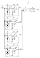
- FIG. 2 is a block diagram illustrating a detailed configuration of the stochastic resonance unit.
- FIG. 3 is a diagram illustrating a time waveform of an input signal that is a radiation detection signal input to the stochastic resonance unit.
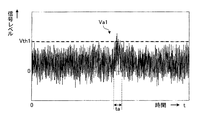
- FIG. 4 is a diagram illustrating a time waveform of the noise addition signal output from the noise adder.
- FIG. 5 is a diagram illustrating a time waveform of the threshold processing signal output from the comparator.
- FIG. 6 is a diagram illustrating a time waveform of an addition signal obtained by adding all the threshold processing signals by the addition unit.
- FIG. 1 is a schematic diagram showing an overall configuration of a radiation detection apparatus according to Embodiment 1 of the present invention.
- FIG. 2 is a block diagram illustrating a detailed configuration of the stochastic resonance unit.
- FIG. 3 is a diagram illustrating a time waveform of an input signal
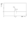
- FIG. 7 is a diagram illustrating a time waveform of an output signal which is a waveform reproduction signal output from the waveform reproduction unit.
- FIG. 8 is a circuit diagram showing a configuration of a stochastic resonance unit according to Embodiment 2 of the present invention.
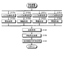
- FIG. 9 is a flowchart showing a radiation dose measurement processing procedure by the radiation dose measurement processing program according to the third embodiment of the present invention.
- FIG. 1 is a schematic diagram showing an overall configuration of a radiation detection apparatus according to Embodiment 1 of the present invention.
- the radiation detection apparatus 1 includes a radiation detection unit 2 and a signal processing unit 3.
- the radiation detection unit 2 includes a scintillator 4, a light guide 5, and a light receiving element 6.
- the signal processing unit 3 includes a stochastic resonance unit 7 and a calculation unit 8.
- the scintillator 4 generates scintillation light according to the energy of the radiation R when the radiation R enters from the outside, and the scintillation light enters the light guide 5 that supports the scintillator 4.
- the light guide 5 is tapered, the scintillator 4 is disposed on one end surface having a large area, and the light receiving element 6 is disposed on the other end surface having a small area.
- the scintillation light incident on the light guide 5 reaches the light receiving element 6 having a small light receiving area while repeating reflection.
- the light receiving element 6 outputs a light reception signal obtained by photoelectric conversion in accordance with the amount of incident scintillation light, and outputs the output signal to the stochastic resonance unit 7 of the signal processing unit 3 as an input signal Vin to the stochastic resonance unit 7. .
- This input signal Vin is a radiation detection signal detected by the radiation detection unit 2.
- the stochastic resonance unit 7 reproduces the waveform of the input signal Vin with high sensitivity even by the stochastic resonance process even if the input signal Vin is buried in noise, which has been impossible to detect in the past.
- Stochastic resonance is a phenomenon in which when an optimal noise is added to a nonlinear system with a potentially weak rhythm (weak signal), the rhythm (weak signal) that has been hidden until then becomes obvious and is detected with high sensitivity. is there.
- the stochastic resonance unit 7 generates a stochastic resonance phenomenon with respect to the input signal Vin input from the light receiving element 6 to generate an output signal Vout which is a waveform reproduction signal obtained by reproducing the waveform of the radiation detection signal, and outputs the output signal Vout to the calculation unit 8 To do.
- the radiation detection signal (input signal Vin) of the radiation R is a pulse signal
- the output signal Vout is also a pulse signal.
- the calculation unit 8 performs a calculation for measuring the radiation dose based on the magnitude and number of the output signal Vout that is a pulse signal.
- the radiation dose that is the calculation result is output to a display unit, a communication unit, and the like (not shown).
- FIG. 2 is a block diagram showing a detailed configuration of the stochastic resonator 7.
- the stochastic resonance unit 7 includes four stochastic resonance basic units 40a to 40d, an adding unit 30, and a waveform reproducing unit 50.
- the four stochastic resonance basic units 40a to 40d are connected in parallel and receive the input signal Vin.
- Each of the stochastic resonance basic units 40a to 40d includes a noise adding unit 10a to 10d and a threshold processing unit 20a to 20d, respectively.
- the noise adding units 10a to 10d include noise adders 11a to 11d and noise sources 12a to 12d, respectively.
- the threshold processing units 20a to 20d include threshold voltage sources 21a to 21d and comparators 22a to 22d, respectively.
- Each of the noise adders 11a to 11d adds the noise signals Vn1 to Vn4 output from the noise sources 12a to 12d to the input signal Vin, respectively, so that the noise addition signals Va1 to Va4 are comparators 22a to 22d, respectively. Output to.
- the noise signals Vn1 to Vn4 are uncorrelated signals.
- the noise signals Vn1 to Vn4 are preferably white noise signals, but are not limited to this, and may be other types of noise signals.
- Each of the comparators 22a to 22d receives the above-described noise addition signals Va1 to Va4 and the threshold signals Vth1 to Vth4 output from the threshold voltage sources 21a to 21d, respectively.
- Each of the comparators 22a to 22d is a high level signal when the input noise addition signals Va1 to Va4 are equal to or higher than the threshold signals Vth1 to Vth4, respectively, and a low level signal when the input noise addition signals Va1 to Vth4 are lower than the threshold signals Vth1 to Vth4, respectively.
- Threshold value processing signals Vc1 to Vc4 are output as pulse signals.
- the threshold processing signals Vc1 to Vc4 are input to the adding unit 30. Note that the values of the threshold signals Vth1 to Vth4 are set to values greater than the noise level included in the input signal Vin and the signal levels of the noise signals Vn1 to Vn4.
- the addition unit 30 adds the four threshold processing signals Vc1 to Vc4 input from the comparators 22a to 22d, and outputs the result to the waveform reproduction unit 50 as an addition signal Vad.
- the waveform reproduction unit 50 smoothes the input addition signal Vad and outputs an output signal Vout obtained by performing waveform reproduction of the original input signal Vin.
- each of the stochastic resonance basic units 40a to 40d generates a stochastic resonance phenomenon that can improve the S / N of the input signal Vin and increase the detection sensitivity.
- minute signals below the threshold signals Vth1 to Vth4 cannot be detected.
- minute signals (thresholds below the threshold signals Vth1 to Vth4) due to the stochastic resonance phenomenon ( Even in the case of the input signal Vin), only the input signal Vin can be emphasized and output out of the noise.
- FIG. 3 is a diagram showing a time waveform of the input signal Vin.
- the pulsed radiation detection signal P detected by the light receiving element 6 exists in the period ta. Since this pulsed radiation detection signal P is a weak signal buried in noise, it could not be detected conventionally.
- FIG. 4 is a diagram showing a time waveform of the noise addition signal Va1 output from the noise adder 11a.
- the noise addition signal Va1 is obtained by adding the noise signal Vn1 to the input signal Vin.
- the noise signal Vn1 in the period ta is equal to or higher than the threshold signal Vth1.
- FIG. 5 is a diagram showing a time waveform of the threshold processing signal Vc1 output from the comparator 22a. As shown in FIG. 5, in the period ta, a pulsed signal P1 corresponding to the pulsed radiation detection signal P is output by the stochastic resonance phenomenon.
- FIG. 6 is a diagram illustrating a time waveform of the addition signal Vad obtained by adding all the threshold processing signals Vc1 to Vc4 by the addition unit 30.
- a stepped signal P2 having a waveform close to the pulsed radiation detection signal P is output in the period ta.
- FIG. 7 is a diagram showing a time waveform of the output signal Vout output from the waveform reproducing unit 50.
- the waveform reproduction unit 50 is a frequency filter circuit, and is a low-pass filter that removes a stepped high-frequency component. Note that the cutoff frequency of the low-pass filter needs to be set to a sufficiently large value with respect to the signal frequency calculated from the pulse width of the pulsed radiation detection signal P.
- the waveform reproduction signal P3 appearing in the period ta is smoother than the addition signal Vad shown in FIG. 6, and substantially the same waveform as the signal waveform of the pulsed radiation detection signal P is reproduced.
- the noise signals Vn1 to Vn4 are uncorrelated signals. Therefore, by increasing the parallel number of the stochastic resonance basic units 40a to 40d, the waveform reproduction closer to the pulsed radiation detection signal P can be obtained. It can be performed.
- the number of parallelizations of the stochastic resonance basic units 40a to 40d is four, but this number is merely an example.
- a stochastic resonance phenomenon is generated by the stochastic resonator 7 having a simple configuration, unnecessary noise is deleted from the input signal Vin, and the S / N ratio of the pulsed radiation detection signal P is greatly improved. Therefore, the radiation detection sensitivity can be improved with a simple configuration.
- the radiation detection sensitivity can be increased by using an inexpensive semiconductor light receiving element such as an avalanche photodiode without using an expensive light receiving element such as a photomultiplier tube.
- the signal processing unit 3 described above may be analog signal processing, or may perform digital signal processing by A / D converting the input signal Vin.
- the signal processing unit 3 is integrated by an FPGA.
- the four stochastic resonance basic units 40a to 40d are arranged in parallel.
- the stochastic resonance unit 7 can be configured by only one stochastic resonance basic unit 40a.
- FIG. 8 is a circuit diagram showing a configuration of the stochastic resonance unit according to the second embodiment of the present invention.
- the stochastic resonance unit 17 is arranged in the stochastic resonance unit 7 and includes one stochastic resonance basic unit 40 a used in the first embodiment and a waveform reproduction unit 60.
- the stochastic resonance basic unit 40a outputs the input signal Vin to the waveform reproducing unit 60 as the threshold processing signal Vc1 shown in FIG.
- the waveform reproduction unit 60 performs a moving average on the pulsed signal P1 corresponding to the pulsed radiation detection signal P in a predetermined sampling period, and finally reproduces the pulsed radiation detection signal P from the pulsed signal P1. P3 is generated.
- the waveform reproduction unit 60 outputs the waveform reproduction signal P3 as the output signal Vout.
- the moving average is a kind of low-pass filter processing.
- the signal processing unit 3 has a hardware configuration such as an electronic circuit.
- processing corresponding to the signal processing unit 3 is performed by digital signal processing using software. I am doing so.
- the digital signal processing is executed by a radiation dose measurement processing program.
- the input signal Vin is directly A / D converted using a high-speed A / D conversion element or the like, taken into an arithmetic unit including a CPU and a memory, and a radiation dose measurement program held in the memory is used to
- a series of radiation dose measurement processing that is, noise addition processing, threshold processing, addition processing, waveform reproduction processing, radiation dose measurement processing, and the like are executed.
- the arithmetic device including the CPU and the memory and the radiation dose measurement processing program are preferably configured as the signal processing unit 3.
- the CPU may execute only the processing of the stochastic resonance unit 7 using a program.
- FIG. 9 is a flowchart showing a radiation dose measurement processing procedure by the radiation dose measurement processing program according to the third embodiment of the present invention.
- the CPU performs parallel processing on the processes corresponding to the stochastic resonance basic units 40a to 40d (steps S101a, S102a, S101b, S102b, S101c, S102c, S101d, S102d). That is, after the addition process (step S101a) corresponding to the noise addition unit 10a, the CPU performs a first process for performing a threshold process (step S102a) corresponding to the threshold processing unit 20a and an addition process corresponding to the noise addition unit 10b (step S102a).
- step S101b After step S101b), a second process for performing a threshold process corresponding to the threshold processing unit 20b (step S102b), an addition process corresponding to the noise adding unit 10c (step S101c), and a threshold process corresponding to the threshold processing unit 20c (step S101b)
- step S102b The third process for performing step S102c) and the fourth process for performing the threshold process (step S102d) corresponding to the threshold processing unit 20d after the addition process (step S101d) corresponding to the noise addition unit 10d are performed in parallel.
- the CPU performs an addition process corresponding to the addition unit 30 (step S103). Thereafter, the CPU performs a waveform reproduction process corresponding to the waveform reproduction unit 50 (step S104). Further, the CPU performs a radiation dose measurement process corresponding to the calculation unit 8 (step S105). Thereafter, the CPU repeats the above-described processing every predetermined sampling period. The entire process described above is performed for each sampling data of the input signal Vin. However, the waveform reproduction process in step S104 and the radiation dose measurement process in step S105 are performed by holding past time-series sampling data in a memory.
- the processing of the signal processing unit 3 is performed by the radiation dose measurement processing program, it is possible to flexibly design and change the design for various radiation detection devices, and to greatly reduce circuit components. can do.
- the radiation detector 2 uses the scintillator 4 and the light receiving element 6 receives the scintillator light from the scintillator 4 and detects the pulsed radiation detection signal P.
- the pulsed radiation detection signal P may be detected by a radiation detection element that directly detects radiation without using the scintillator 4. That is, the radiation detector 2 only needs to generate an output signal (pulsed radiation detection signal P) corresponding to the energy of the incident radiation R.
Landscapes
- Physics & Mathematics (AREA)
- Health & Medical Sciences (AREA)
- Life Sciences & Earth Sciences (AREA)
- General Physics & Mathematics (AREA)
- High Energy & Nuclear Physics (AREA)
- Molecular Biology (AREA)
- Spectroscopy & Molecular Physics (AREA)
- Measurement Of Radiation (AREA)
Abstract
Description
[全体構成]
図1は、本発明の実施の形態1である放射線検出装置の全体構成を示す模式図である。図1に示すように、放射線検出装置1は、放射線検出部2と信号処理部3とを有する。放射線検出部2は、シンチレータ4、ライトガイド5、及び受光素子6を有する。また、信号処理部3は、確率共鳴部7及び演算部8を有する。
図2は、確率共鳴部7の詳細構成を示すブロック図である。図2に示すように、確率共鳴部7は、4つの確率共鳴基本部40a~40d、加算部30、及び波形再生部50を有する。4つの確率共鳴基本部40a~40dは、並列接続され、入力信号Vinがそれぞれ入力される。
つぎに、確率共鳴部7内の信号波形をもとに確率共鳴部7の処理について説明する。まず、図3は、入力信号Vinの時間波形を示す図である。図3に示すように、入力信号Vinには、雑音に埋もれてはいるものの、受光素子6が検出したパルス状放射線検出信号Pが期間taに存在する。このパルス状放射線検出信号Pは雑音に埋もれた微弱信号であるため、従来は検出できなかった。
上述した実施の形態1では、4つの確率共鳴基本部40a~40dを並列化した構成であったが、1つの確率共鳴基本部40aのみによっても確率共鳴部7を構成することができる。
上述した実施の形態1,2は、信号処理部3を電子回路などのハードウェア構成としていたが、本実施の形態3では、信号処理部3に対応する処理を、ソフトウェアによるデジタル信号処理を行うようにしている。また、このデジタル信号処理は、放射線量計測処理プログラムによって実行されるようにしている。この場合、高速なA/D変換素子などを用いて入力信号Vinを直接、A/D変換してCPU及びメモリを含む演算装置に取り込み、メモリに保持された放射線量計測プログラムを用いて、CPUが、一連の放射線量計測処理、すなわちノイズ加算処理、閾値処理、加算処理、波形再生処理、放射線量計測処理などを実行する。なお、CPU及びメモリを含む演算装置及び放射線量計測処理プログラムは信号処理部3として構成されることが好ましい。また、CPUは、確率共鳴部7の処理のみをプログラムを用いて実行するようにしてもよい。
2 放射線検出部
3 信号処理部
4 シンチレータ
5 ライトガイド
6 受光素子
7,17 確率共鳴部
8 演算部
10a~10d ノイズ加算部
11a~11d ノイズ加算器
12a~12d ノイズ源
20a~20d 閾値処理部
21a~21d 閾値電圧源
22a~22d 比較器
30 加算部
40a~40d 確率共鳴基本部
50,60 波形再生部
P パルス状放射線検出信号
P1 パルス状信号
P2 段階状信号
P3 波形再生信号
R 放射線
ta 期間
Va1~Va4 ノイズ加算信号
Vad 加算信号
Vc1~Vc4 閾値処理信号
Vin 入力信号
Vn1~Vn4 ノイズ信号
Vout 出力信号
Vth1~Vth4 閾値信号
Claims (5)
- 入射した放射線のエネルギーに応じて放射線検出信号を生成する放射線検出部と、
前記放射線検出部が生成した放射線検出信号に確率共鳴現象を生じさせて前記放射線検出信号を波形再生した波形再生信号を出力する確率共鳴部と、
前記確率共鳴部が生成した波形再生信号に基づいて放射線量を計測する演算部と、
を備えたことを特徴とする放射線検出装置。 - 前記確率共鳴部は、
前記放射線検出部が生成した放射線検出信号にノイズ信号を加算したノイズ加算信号を生成するノイズ加算部と、
前記ノイズ加算部が生成したノイズ加算信号が所定の閾値以上である場合にハイレベルとするパルス信号を出力する閾値処理を行う閾値処理部と、
前記閾値処理部から出力されたパルス信号を平滑化した波形再生信号を出力する波形再生部と、
を備えたことを特徴とする請求項1に記載の放射線検出装置。 - 前記確率共鳴部は、
前記放射線検出部が生成した放射線検出信号にノイズ信号を加算したノイズ加算信号を生成するノイズ加算部と、
前記ノイズ加算部が生成したノイズ加算信号が所定の閾値以上である場合にハイレベルとするパルス信号を出力する閾値処理を行う閾値処理部と、
を有した複数の確率共鳴基本部を並列配置し、
各確率共鳴基本部から出力されたパルス信号を加算したパルス加算信号を出力するパルス加算部と、
前記パルス加算部が出力したパルス加算信号を平滑化した波形再生信号を出力する波形再生部と、
を備えたことを特徴とする請求項1に記載の放射線検出装置。 - 入射した放射線のエネルギーに応じて生成される放射線検出信号に確率共鳴現象を生じさせて前記放射線検出信号を波形再生した波形再生信号を出力し、
前記波形再生信号に基づいて放射線量を計測することを特徴とする放射線量計測処理方法。 - プロセッサに、
入射した放射線のエネルギーに応じて生成される放射線検出信号に確率共鳴現象を生じさせて前記放射線検出信号を波形再生した波形再生信号を出力し、
前記波形再生信号に基づいて放射線量を計測する、
処理を実行させることを特徴とする放射線量計測処理プログラム。
Priority Applications (2)
| Application Number | Priority Date | Filing Date | Title |
|---|---|---|---|
| JP2015526805A JP5861803B1 (ja) | 2014-02-27 | 2014-08-04 | 放射線検出装置、放射線量計測処理方法、及び放射線量計測処理プログラム |
| CN201480048230.3A CN105492929B (zh) | 2014-02-27 | 2014-08-04 | 放射线检测装置及放射剂量测量处理方法 |
Applications Claiming Priority (2)
| Application Number | Priority Date | Filing Date | Title |
|---|---|---|---|
| JP2014037222 | 2014-02-27 | ||
| JP2014-037222 | 2014-02-27 |
Publications (1)
| Publication Number | Publication Date |
|---|---|
| WO2015129069A1 true WO2015129069A1 (ja) | 2015-09-03 |
Family
ID=54008421
Family Applications (1)
| Application Number | Title | Priority Date | Filing Date |
|---|---|---|---|
| PCT/JP2014/070513 Ceased WO2015129069A1 (ja) | 2014-02-27 | 2014-08-04 | 放射線検出装置、放射線量計測処理方法、及び放射線量計測処理プログラム |
Country Status (3)
| Country | Link |
|---|---|
| JP (1) | JP5861803B1 (ja) |
| CN (1) | CN105492929B (ja) |
| WO (1) | WO2015129069A1 (ja) |
Cited By (2)
| Publication number | Priority date | Publication date | Assignee | Title |
|---|---|---|---|---|
| JP2021034447A (ja) * | 2019-08-20 | 2021-03-01 | 株式会社東芝 | 放射線検出器 |
| JP2022074778A (ja) * | 2020-11-05 | 2022-05-18 | 株式会社東芝 | 放射線検出器 |
Citations (2)
| Publication number | Priority date | Publication date | Assignee | Title |
|---|---|---|---|---|
| WO2011065500A1 (ja) * | 2009-11-30 | 2011-06-03 | 国立大学法人北海道大学 | 信号再生装置 |
| JP2013135244A (ja) * | 2011-12-23 | 2013-07-08 | Toyota Central R&D Labs Inc | 信号再生装置及び信号再生方法 |
Family Cites Families (8)
| Publication number | Priority date | Publication date | Assignee | Title |
|---|---|---|---|---|
| JP2009049280A (ja) * | 2007-08-22 | 2009-03-05 | Sharp Corp | 半導体光増幅素子及び脈波計測装置 |
| JP4700705B2 (ja) * | 2008-02-29 | 2011-06-15 | 独立行政法人科学技術振興機構 | 信号再生装置 |
| JP2010078338A (ja) * | 2008-09-24 | 2010-04-08 | Toshiba Corp | X線検出器 |
| CN101561293B (zh) * | 2009-05-11 | 2011-09-07 | 天津大学 | 基于随机共振的微弱特征信息恢复系统 |
| JP2011052991A (ja) * | 2009-08-31 | 2011-03-17 | Panasonic Corp | S/n特性改善器 |
| US9000385B2 (en) * | 2009-12-30 | 2015-04-07 | General Electric Company | Method and apparatus for acquiring radiation data |
| JP5510182B2 (ja) * | 2010-08-19 | 2014-06-04 | 株式会社島津製作所 | 放射線断層撮影装置 |
| WO2013121831A1 (ja) * | 2012-02-17 | 2013-08-22 | 株式会社日立製作所 | 微小信号検出方法及びシステム |
-
2014
- 2014-08-04 JP JP2015526805A patent/JP5861803B1/ja not_active Expired - Fee Related
- 2014-08-04 CN CN201480048230.3A patent/CN105492929B/zh not_active Expired - Fee Related
- 2014-08-04 WO PCT/JP2014/070513 patent/WO2015129069A1/ja not_active Ceased
Patent Citations (2)
| Publication number | Priority date | Publication date | Assignee | Title |
|---|---|---|---|---|
| WO2011065500A1 (ja) * | 2009-11-30 | 2011-06-03 | 国立大学法人北海道大学 | 信号再生装置 |
| JP2013135244A (ja) * | 2011-12-23 | 2013-07-08 | Toyota Central R&D Labs Inc | 信号再生装置及び信号再生方法 |
Non-Patent Citations (2)
| Title |
|---|
| KOJI KASHIHARA ET AL.: "Bisho Level no Eizo Shingo kara Jomyaku Keijo o Ko Seido ni Suitei suru Tameno Kaiseki Shuho no Kento", IEICE TECHNICAL REPORT, vol. 111, no. 259, 17 October 2011 (2011-10-17), pages 49 - 54 * |
| YUKI YAMAMOTO ET AL.: "Improvement of Contrast Resolution Using Stochastic Resonance", THE INSTITUTE OF ELECTRONICS, INFORMATION AND COMMUNICATION ENGINEERS GIJUTSU KENSHU HOKOKU, vol. 113, no. 250, 11 October 2013 (2013-10-11), pages 7 - 10 * |
Cited By (5)
| Publication number | Priority date | Publication date | Assignee | Title |
|---|---|---|---|---|
| JP2021034447A (ja) * | 2019-08-20 | 2021-03-01 | 株式会社東芝 | 放射線検出器 |
| JP7218257B2 (ja) | 2019-08-20 | 2023-02-06 | 株式会社東芝 | 放射線検出器 |
| JP2022074778A (ja) * | 2020-11-05 | 2022-05-18 | 株式会社東芝 | 放射線検出器 |
| JP7434135B2 (ja) | 2020-11-05 | 2024-02-20 | 株式会社東芝 | 放射線検出器 |
| US12235397B2 (en) | 2020-11-05 | 2025-02-25 | Kabushiki Kaisha Toshiba | Radiation detector |
Also Published As
| Publication number | Publication date |
|---|---|
| CN105492929A (zh) | 2016-04-13 |
| JP5861803B1 (ja) | 2016-02-16 |
| JPWO2015129069A1 (ja) | 2017-03-30 |
| CN105492929B (zh) | 2017-06-13 |
Similar Documents
| Publication | Publication Date | Title |
|---|---|---|
| JP6657398B2 (ja) | パルスパイルアップイベントのリアルタイム処理の方法及びシステム | |
| CN109581461B (zh) | 核脉冲能量测量方法及系统 | |
| JP2011508201A5 (ja) | ||
| WO2014173644A1 (en) | Detection of radiation quanta using an optical detector pixel array and pixel cell trigger state sensing circuits | |
| US9244179B2 (en) | Time-based digitizer for PET photodetector | |
| WO2016110141A1 (zh) | 一种闪烁脉冲的数字化方法 | |
| WO2017016469A1 (zh) | 光子测量前端电路 | |
| RU2011105130A (ru) | Детекторная система для измерения излучения | |
| WO2015070578A1 (zh) | 伽马射线探测器和伽马射线的处理方法 | |
| CN109283569B (zh) | 用于测量光子信息的装置和光子测量设备 | |
| CN103412319A (zh) | 基于脉冲宽度谱的探测器信号处理方法和装置 | |
| CN106706127A (zh) | 基于SiPM的多光子探测方法 | |
| Tang et al. | A new method for removing false peaks to obtain a precise X-ray spectrum | |
| JP5861803B1 (ja) | 放射線検出装置、放射線量計測処理方法、及び放射線量計測処理プログラム | |
| CN103607205B (zh) | 一种信号处理方法、装置及设备 | |
| JP7057630B2 (ja) | 放射線検出装置 | |
| CN110988961B (zh) | 信号处理方法、装置和探测系统 | |
| CN108008438B (zh) | 一种射线能量的测量装置及方法 | |
| JP2017044518A (ja) | 信号処理装置及び放射線測定装置 | |
| JP2003043149A (ja) | 放射線検出回路 | |
| CN105940321A (zh) | 放射线检测器 | |
| CN102291118A (zh) | 一种单光子计数放大/甄别电路 | |
| CN111142148A (zh) | 一种位置敏感型闪烁探测器的倒装sql方法 | |
| JP6938239B2 (ja) | 光検出器及び光検出装置 | |
| González et al. | Data Acquisition in particle physics experiments |
Legal Events
| Date | Code | Title | Description |
|---|---|---|---|
| WWE | Wipo information: entry into national phase |
Ref document number: 201480048230.3 Country of ref document: CN |
|
| ENP | Entry into the national phase |
Ref document number: 2015526805 Country of ref document: JP Kind code of ref document: A |
|
| 121 | Ep: the epo has been informed by wipo that ep was designated in this application |
Ref document number: 14883833 Country of ref document: EP Kind code of ref document: A1 |
|
| WWE | Wipo information: entry into national phase |
Ref document number: 2016/02844 Country of ref document: TR |
|
| NENP | Non-entry into the national phase |
Ref country code: DE |
|
| 122 | Ep: pct application non-entry in european phase |
Ref document number: 14883833 Country of ref document: EP Kind code of ref document: A1 |