WO2015129016A1 - 情報記録再生装置および情報記録方法 - Google Patents
情報記録再生装置および情報記録方法 Download PDFInfo
- Publication number
- WO2015129016A1 WO2015129016A1 PCT/JP2014/055001 JP2014055001W WO2015129016A1 WO 2015129016 A1 WO2015129016 A1 WO 2015129016A1 JP 2014055001 W JP2014055001 W JP 2014055001W WO 2015129016 A1 WO2015129016 A1 WO 2015129016A1
- Authority
- WO
- WIPO (PCT)
- Prior art keywords
- post
- recording
- cure
- information
- recording medium
- Prior art date
Links
- 238000000034 method Methods 0.000 title claims abstract description 81
- 230000008569 process Effects 0.000 claims abstract description 54
- 230000003287 optical effect Effects 0.000 claims abstract description 41
- 238000011417 postcuring Methods 0.000 claims abstract description 20
- 230000001678 irradiating effect Effects 0.000 claims abstract description 17
- 238000012545 processing Methods 0.000 claims description 94
- 238000013036 cure process Methods 0.000 claims description 69
- 238000001093 holography Methods 0.000 abstract description 10
- 230000009467 reduction Effects 0.000 abstract description 2
- 230000000694 effects Effects 0.000 description 9
- 238000010586 diagram Methods 0.000 description 6
- 230000006870 function Effects 0.000 description 6
- 230000002093 peripheral effect Effects 0.000 description 6
- 238000001514 detection method Methods 0.000 description 5
- 239000000178 monomer Substances 0.000 description 4
- 230000010287 polarization Effects 0.000 description 4
- 238000006116 polymerization reaction Methods 0.000 description 4
- 230000007274 generation of a signal involved in cell-cell signaling Effects 0.000 description 3
- 230000007246 mechanism Effects 0.000 description 3
- 230000004048 modification Effects 0.000 description 3
- 238000012986 modification Methods 0.000 description 3
- 238000006243 chemical reaction Methods 0.000 description 2
- 238000013461 design Methods 0.000 description 2
- 239000000463 material Substances 0.000 description 2
- 238000005457 optimization Methods 0.000 description 2
- 229920000642 polymer Polymers 0.000 description 2
- 230000004913 activation Effects 0.000 description 1
- 230000015556 catabolic process Effects 0.000 description 1
- 230000008859 change Effects 0.000 description 1
- 238000006731 degradation reaction Methods 0.000 description 1
- 230000010354 integration Effects 0.000 description 1
- 230000000379 polymerizing effect Effects 0.000 description 1
- 238000002360 preparation method Methods 0.000 description 1
- 239000007787 solid Substances 0.000 description 1
Images


Classifications
-
- G—PHYSICS
- G03—PHOTOGRAPHY; CINEMATOGRAPHY; ANALOGOUS TECHNIQUES USING WAVES OTHER THAN OPTICAL WAVES; ELECTROGRAPHY; HOLOGRAPHY
- G03H—HOLOGRAPHIC PROCESSES OR APPARATUS
- G03H1/00—Holographic processes or apparatus using light, infrared or ultraviolet waves for obtaining holograms or for obtaining an image from them; Details peculiar thereto
- G03H1/04—Processes or apparatus for producing holograms
- G03H1/18—Particular processing of hologram record carriers, e.g. for obtaining blazed holograms
- G03H1/182—Post-exposure processing, e.g. latensification
-
- G—PHYSICS
- G11—INFORMATION STORAGE
- G11B—INFORMATION STORAGE BASED ON RELATIVE MOVEMENT BETWEEN RECORD CARRIER AND TRANSDUCER
- G11B7/00—Recording or reproducing by optical means, e.g. recording using a thermal beam of optical radiation by modifying optical properties or the physical structure, reproducing using an optical beam at lower power by sensing optical properties; Record carriers therefor
- G11B7/004—Recording, reproducing or erasing methods; Read, write or erase circuits therefor
- G11B7/0065—Recording, reproducing or erasing by using optical interference patterns, e.g. holograms
Definitions
- the present invention relates to an information recording / reproducing apparatus and an information recording method for recording information using holography.
- Patent Document 1 JP-A-2009-43369. This gazette states that “the post-cure performed on a predetermined range including the portion where the data was recorded and its surroundings is used to reduce the range that cannot be recorded at the time of later appending, thereby improving the data recording density. (See summary).
- an object of the present invention is to provide a data recording / reproducing apparatus and a data recording method for eliminating the influence of post-cure processing on an unrecorded area in a data recording / reproducing apparatus for recording / reproducing digital information using holography. It is.
- Schematic diagram showing an embodiment of a data recording / reproducing apparatus Relationship diagram between irradiation energy and multiple recording performance index Schematic showing an embodiment of a pickup in a data recording / reproducing apparatus
- Schematic showing an embodiment of a pickup in a data recording / reproducing apparatus The flowchart showing the Example of operation
- FIG. 1 is a block diagram showing a recording / reproducing apparatus for a recording medium for recording and / or reproducing digital information using holography.
- the data recording / reproducing device 10 is connected to the control device 91 via the input / output control unit 90.
- the data recording / reproducing apparatus 10 receives an information signal to be recorded from the control apparatus 91 by the input / output control unit 90.
- the data recording / reproducing apparatus 10 transmits the reproduced information signal to the control apparatus 91 by the input / output control unit 90.
- the control device 91 may be a device that is directly connected to the data recording / reproducing device 10 or may be a device that is indirectly connected via another device on the higher level side.
- the data recording / reproducing apparatus 10 includes a pickup 11, a reproduction reference light optical system 12, a cure optical system 13, a medium rotation angle detection optical system 14, and a rotation motor 50, and the recording medium 1 is rotated by the rotation motor 50. It has a possible configuration.
- the pickup 11 includes a light source, and plays a role of recording digital information on the recording medium using holography by irradiating the recording medium 1 with reference light and signal light.
- the information signal to be recorded is sent by the controller 89 to the spatial light modulator in the pickup 11 via the signal generator 86, and the signal light is modulated by the spatial light modulator.
- the reproduction reference light optical system 12 When reproducing the information recorded on the recording medium 1, the reproduction reference light optical system 12 generates a light wave that causes the reference light emitted from the pickup 11 to enter the recording medium in a direction opposite to that at the time of recording.
- the reproduction light reproduced by the reproduction reference light is detected by a photodetector described later in the pickup 11, and the signal is reproduced by the signal processing unit 85.
- the irradiation time of the reference light and the signal light applied to the recording medium 1 can be adjusted by controlling the opening / closing time of the shutter in the pickup 11 via the shutter control unit 87 by the controller 89.
- the cure optical system 13 plays a role of generating a light beam used for pre-cure and post-cure of the recording medium 1.
- Precure is a pre-process for irradiating a predetermined light beam in advance before irradiating the reference light and signal light to the desired position when recording information at the desired position in the recording medium 1.
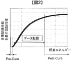
- Hologram recording refers to changing the recording material of the medium from monomer to polymer.
- the horizontal axis indicates the irradiation energy
- the vertical axis indicates the recording index indicating the multiple recording performance
- the hologram is multiplexed (recorded) by irradiating the medium with energy
- the region irradiated with energy is shown. This means that the monomer is consumed.
- Pre-cure is a process necessary before data recording in FIG. 2, and is a process for keeping the recording medium in a state immediately before the activation of the reaction. Note that the pre-cure process is not necessarily required if the recording medium has a characteristic that does not require energy irradiation with a light beam.
- Post-cure is a post-process in which, after information is recorded at a desired position in the recording medium 1, a predetermined light beam is irradiated so that additional recording cannot be performed at the desired position.
- the post-cure process is a process necessary after data recording in FIG. 2 and is a process for consuming (polymerizing) all remaining monomers and preventing the recorded area from reacting with the light beam any more. This post-cure process prevents unnecessary noise from being recorded in the recorded area.
- the post-curing process of the recorded area is performed after the recording process is completed.
- This time limit is called a post-cure timeout time.
- the medium rotation angle detection optical system 14 is used to detect the rotation angle of the recording medium 1.
- a signal corresponding to the rotation angle is detected by the medium rotation angle detection optical system 14, and the medium rotation motor control unit 88 is controlled by the controller 89 using the detected signal.
- the rotation angle of the recording medium 1 can be controlled via
- a predetermined light source supply current is supplied from the light source driving unit 82 to the light sources in the pickup 11, the cure optical system 13, and the medium rotation angle detection optical system 14, and each light source emits a light beam with a predetermined light amount. can do.
- the pickup 11 and the medium cure optical system 13 are provided with a mechanism capable of sliding the position in the radial direction of the recording medium 1, and position control is performed via the access control unit 81.
- the recording technology using the principle of angle multiplexing of holography tends to have a very small tolerance for the deviation of the reference beam angle.
- a mechanism for detecting the deviation amount of the reference beam angle is provided in the pickup 11, a servo control signal is generated by the servo signal generation unit 83, and the deviation amount is corrected via the servo control unit 84. It is necessary to provide a servo mechanism for this in the data recording / reproducing apparatus 10.
- the pickup 11, the cure optical system 13, and the medium rotation angle detection optical system 14 may be simplified by combining several optical system configurations or all optical system configurations.
- FIG. 3 shows a recording principle in an example of a basic optical system configuration of the pickup 11 in the data recording / reproducing apparatus 10.
- the light beam emitted from the light source 301 passes through the collimator lens 302 and enters the shutter 303.
- the shutter 303 When the shutter 303 is open, after the light beam passes through the shutter 303, the optical ratio of the p-polarized light and the s-polarized light becomes a desired ratio by the optical element 304 composed of, for example, a half-wave plate.
- the optical element 304 composed of, for example, a half-wave plate.
- the light is incident on a PBS (Polarization Beam Splitter) prism 305.
- PBS Polarization Beam Splitter
- the light beam that has passed through the PBS prism 305 functions as signal light 306, and after the light beam diameter is expanded by the beam expander 308, the light beam passes through the phase mask 309, the relay lens 310, and the PBS prism 311 and passes through the spatial light modulator 312. Is incident on.
- the signal light to which information is added by the spatial light modulator 312 reflects the PBS prism 311 and propagates through the relay lens 313 and the spatial filter 314. Thereafter, the signal light is condensed on the recording medium 1 by the objective lens 315.
- the light beam reflected by the PBS prism 305 functions as reference light 307 and is set to a predetermined polarization direction according to recording or reproduction by the polarization direction conversion element 316, and then passes through the mirror 317 and the mirror 318.
- the galvanometer mirror 319 Incident on the galvanometer mirror 319. Since the angle of the galvanometer mirror 319 can be adjusted by the actuator 320, the incident angle of the reference light incident on the recording medium 1 after passing through the lens 321 and the lens 322 can be set to a desired angle. In order to set the incident angle of the reference light, an element that converts the wavefront of the reference light may be used instead of the galvanometer mirror.
- the signal light and the reference light are incident on the recording medium 1 so as to overlap each other, whereby an interference fringe pattern is formed in the recording medium, and information is recorded by writing this pattern on the recording medium.
- the incident angle of the reference light incident on the recording medium 1 can be changed by the galvanometer mirror 319, recording by angle multiplexing is possible.
- holograms corresponding to each reference beam angle are called pages, and a set of pages angle-multiplexed in the same area is called a book. .
- FIG. 4 shows a reproduction principle in an example of a basic optical system configuration of the pickup 11 in the data recording / reproducing apparatus 10.
- the reference beam is incident on the recording medium 1 as described above, and the light beam transmitted through the recording medium 1 is reflected by the galvanometer mirror 324 whose angle can be adjusted by the actuator 323.
- the reproduction reference light is generated.
- the reproduction light reproduced by the reproduction reference light propagates through the objective lens 315, the relay lens 313, and the spatial filter 314. Thereafter, the reproduction light passes through the PBS prism 311 and enters the photodetector 325, and the recorded signal can be reproduced.
- the photodetector 325 for example, an image sensor such as a CMOS image sensor or a CCD image sensor can be used. However, any element may be used as long as page data can be reproduced.
- FIG. 5 shows an operation flow of recording and reproduction in the data recording / reproducing apparatus 10.
- a flow relating to recording / reproduction using holography in particular will be described.
- FIG. 5A shows an operation flow from when the recording medium 1 is inserted into the data recording / reproducing apparatus 10 until preparation for recording or reproduction is completed, and FIG. 5B shows from the ready state to the recording medium 1.
- FIG. 5C shows an operation flow until information is recorded, and
- FIG. 5C shows an operation flow until the information recorded on the recording medium 1 is reproduced from the ready state.
- the data recording / reproducing apparatus 10 is, for example, whether the inserted recording medium 1 is a medium for recording or reproducing digital information using holography.
- the medium is determined (502).
- the data recording / reproducing apparatus 10 reads information provided in the recording medium 1 (503), for example, a recording medium 1 and information on various setting conditions during recording and reproduction, for example.
- the operation flow from the ready state (505) to recording information is as follows. First, data to be recorded is received (511), and information corresponding to the data is stored in the space in the pickup 11. Send to optical modulator.
- the data recording / reproducing apparatus 10 may perform the recording learning process (512) before receiving the recording / reproducing data (511). That is, the order of the processes 511 and 512 may be reversed, or may be performed in the process of FIG.
- the access control unit 22 is controlled to position the pickup 11 and the cure optical system 13 at predetermined positions on the recording medium 1.
- the address information is reproduced to check whether the recording medium 1 is positioned at the target position. If the recording medium 1 is not positioned at the target position, the amount of deviation from the predetermined position is calculated. Repeat the positioning operation.
- a predetermined area is pre-cured using the light beam emitted from the cure optical system 13 (514), and data is recorded using the reference light and signal light emitted from the pickup 11 (515).
- the pre-cure process and the post-cure process may be unnecessary depending on the recording characteristics of the recording medium 1, and may be omitted if unnecessary.
- post cure is performed using the light beam emitted from the cure optical system 13 (516). Data may be verified as necessary.
- the operation flow from the ready state (505) until the recorded information is reproduced is as follows.
- the access control unit 22 is controlled to perform the pickup 11 and the reproduction.
- the position of the reference light optical system 12 is positioned at a predetermined position on the recording medium 1.
- the address information is reproduced to check whether the recording medium 1 is positioned at the target position. If the recording medium 1 is not positioned at the target position, the amount of deviation from the predetermined position is calculated. Repeat the positioning operation.
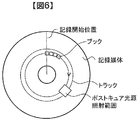
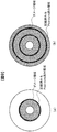
- FIG. 6 shows the book recording direction in this embodiment.
- a method is considered in which a book is arranged on a recording medium along a concentric track and information is recorded on the entire surface of the recording medium. Note that the recording medium is kept stationary during the recording process, and the irradiation position is moved when the next book is recorded.
- FIG. 7 shows an example of the book recording order.
- FIG. 7A shows an example in which book recording processing is sequentially performed along tracks on concentric circles.
- FIG. 7B shows an example in which the recording order of the book is not in order, unlike FIG. 7A, although it is along the track on the concentric circles.
- FIG. 7C shows an example in which the recording process of the first round is performed while skipping one book, and the recording process of the skipped book is performed in the recording process of the second round. Show.
- FIG. 7D shows an example in which recording processing is performed along tracks while straddling a plurality of tracks.
- the order of recording of the books up to that is not limited.
- FIG. 8 shows the damage that the post-cure process has on the peripheral region. Specifically, it shows the effect of post-cure processing on the peripheral area of the recorded area when a book is recorded on multiple tracks within a predetermined angle ⁇ and post-curing processing of the recorded area is performed. ing.
- FIG. 8 shows a damage area schematically showing the influence.
- the damaged area is an area that may be affected by the light beam irradiation for post-cure processing to the already recorded area, and that may cause a decrease in recordable capacity or recording impossible due to progress of polymerization. .
- the recording direction is concentric, if the post-cure process is not performed in concentric units, that is, in units of 360 degrees, a damaged area is also generated in the radial direction of the recording medium.
- the unit of the post-cure process is a concentric unit, that is, a unit of 360 degrees.
- the post-cure processing in this embodiment is performed in concentric units while rotating the recording medium.
- the post-curing light beam is emitted after the rotation of the recording medium is stabilized.
- the size of the post-cure processing light beam applied to the recording medium may be the same size as the signal beam used during recording / reproduction and the light beam of the reference light, and it can handle multiple tracks simultaneously. It may be. When the light beam is large enough to process a plurality of tracks simultaneously, post-cure processing can be performed efficiently.
- the size and rotation speed of the light beam used for the post-cure process must be determined within a range in which the error of the light energy density is acceptable.
- the outer peripheral region where the light energy density is low may be subjected to the post-curing process again at the next post-curing process.
- the recording process does not necessarily have to record all the data concentrically, and since the post-cure process is performed in concentric units, an unrecorded area may be included in the area irradiated with the light beam.
- the energy required for completing the post-cure process differs between the recorded area and the unrecorded area of the data. Therefore, when performing the post-cure process, increase the total rotation time according to the unrecorded area or the unrecorded area. Therefore, it is necessary to consider that the light energy necessary for completing the post-cure process is sufficiently given to the unrecorded area, for example, by processing only this part.
- dummy data may be recorded in an unrecorded area so that the same post-curing light energy as that of other recorded areas is sufficient.
- FIG. 9 shows an example of a damage area generated by the post cure process.
- FIG. 9A shows an example in which recording is performed in concentric units, in which a recording process for a plurality of tracks is performed, and a post-cure process is performed on all the recorded areas.
- FIG. 9B shows a state where this process is repeated for the entire surface of the recording medium. It can be seen that a damaged area is generated as many times as the number of times the recording process is interrupted and the post-cure process is performed, and the recordable capacity is reduced by the damaged area.
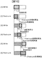
- FIG. 10 shows a schematic diagram of the processing range when the recording and post-cure processes are repeated.
- the pre-curing process is not mentioned in this description, it is assumed that the pre-curing process is always performed before recording.
- the reason for dividing and recording in this case is that the post-cure timeout time is limited as described above. For example, if the recording time becomes longer in (1) of FIG. 10, the first recorded area exceeds the post-cure timeout time in the middle of recording, so the recording is interrupted before the timeout is reached, and the post-cure of (2) Processing needs to be started. After performing the recording process in (1), the post-cure process is performed in (2). Here, the post-cure process is not performed for all the areas subjected to the recording process in (1), and the post-cure process is performed. Leave a part of the area that is not implemented.
- the recording process is performed after the area recorded in (1).
- the post-cure process in (4) the post-cure process is performed together with the post-cure unprocessed area left in (2). Do.
- (2) a part of the area where the post-cure process is not performed is left.
- the post-cure processing target area in (6) is the post-cure unprocessed area left in (4) and all the areas recorded in (5). It becomes the area combined with the area.
- the start position of the post-cure process in (4) may overlap with the area that has been processed in the post-cure process in (2).
- the positioning accuracy of the signal light and the reference light which is a light beam for data recording that must be recorded accurately at the position determined by each coordinate axis, is required to be high precision, but the polymerization of the recording medium is completed
- the positioning accuracy of the light beam for post-cure processing that has only to be irradiated may be lower than that of the light beam for data recording.
- the start position of the post-cure processing in (4) is the same as the area processed in the post-cure processing in (2). It should be set to overlap within the necessary and sufficient range.
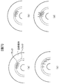
- 11A to 11C show the influence on the post-cure processing range and the unrecorded area.
- the oblique line is the post-cure processing range, and the horizontal line is the range that the post-cure process affects.
- the post-cure processing range within a range that does not affect the unrecorded area as in the post-cure processing of FIGS. 11 (a) and 11 (b). This range varies depending on the recording characteristics of the medium, the recording processing speed, the post-cure processing speed, the processing range, the post-cure timeout time, and the surrounding environment.
- the combined range of the post-curing area and the damaged area is substantially equal to the recorded area. It is better to perform post-cure treatment so that In addition, since there is no problem even if the post-cure process overlaps the previous post-cure process, the post-cure start position may be from the previous end position without considering the surrounding damage area.
- the post-curing process is performed while leaving a part of the recorded area, the next recording is performed, and the remaining post-curing unprocessed area is processed together with the next post-curing process, thereby reducing the recording capacity. Prevents the generation of damage areas that cause damage.
- FIG. 12 illustrates the above description for the entire recording medium.
- FIG. 12 shows the recording processing range and the post-cure processing range over the entire surface of the recording medium.
- FIG. 12A shows an example of recording from the inner periphery
- FIG. 12B shows an example of recording from the outer periphery.
- the oblique lines indicate the recording process and the half lines indicate the post-cure process. In either case, it is possible to record the entire surface of the recording medium without generating a damaged area.
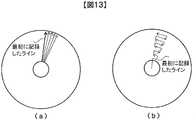
- FIG. 13 shows an example in which the recording order is not concentric. If recording is performed in a direction that is not concentric as shown in FIG. 13, the first recorded line reaches the post-cure timeout time in the middle of recording, so the recording is interrupted and post-cure processing is performed. There is a need to do. As a result, a damaged area is generated by post-cure processing.
- the concentric recording is performed sequentially from the inner circumference to the outer circumference of the recording medium, so that the post cure timeout can be reached concentrically from the inner circumference, that is, in the order of recording.
- the post-cure process can be performed concentrically, and as a result, it is possible to efficiently record on the entire surface of the recording medium without generating a damaged area.
- the post-cure process in the case where the recording process is performed as shown in FIG. 13 may be completed so that the recorded area to be post-cured does not reach the post-cure timeout, and the direction and sequence of the process.
- the order of concentric processing may be from the inner periphery to the outer periphery or vice versa.
- Such a recording direction and order are only inefficient as compared with the case of processing concentrically in order, and the obtained effect is not changed.
- FIG. 14 is a graph showing the recording and post-cure processing, with the horizontal axis representing elapsed time and the vertical axis representing the amount of processing data. As can be seen from this graph, the post-cure processing amount does not catch up with the recording processing amount until the recording is completed. Note that the range of recording processing and post-cure processing varies depending on the characteristics of the medium, recording processing speed, post-cure processing speed, processing range, post-cure timeout time, and surrounding environment, so it is not uniquely determined by the user's design. Matters.
- Steps 1501, 1502, and 1503 are set as one cycle, and this cycle is rotated until the end of recording.
- step 1501 a predetermined range of recording processing is performed. As described above, this range is not uniquely determined but a design item.
- step 1502 After the recording process is completed, it is determined in step 1502 whether or not it is the final recording process.
- post-cure processing is performed in step 1503.
- the post-cure process here is a process in which the entire area subjected to the recording process in step 1501 is not post-cured and a part is left.
- the post-cure process in the N + 1 (N is a natural number) cycle is performed simultaneously with the post-cure of the post-cure target area left in the N-cycle post-cure process.
- “time required for recording processing in step 1501” and “time required for processing of post-curing target area S left unprocessed in step N of step 1503” are set. It is necessary that the added time does not exceed the post cure timeout time of the post cure target area S.
- the determination time in step 1502 is regarded as a time that can be ignored and is not considered here.
- post-cure processing in Step 1503 of the Nth cycle is performed so that a damaged area as shown in FIGS. 8 and 9 does not occur in the unrecorded area in the unrecorded area that is the target area of the N + 1th cycle of the recording process. There is a need to do. If it is determined YES, post-cure processing is performed in step 1504. Unlike post-step 1503, post-cure processing here processes all the recording processing areas in step 1501 and sets post-cure unprocessed areas. Do not leave.
- the recording is performed by concentric circles as an example.
- the recording is not limited to concentric circles, and other recording units can be applied.
- FIG. 16 shows a case where the recording processing unit is not a concentric circle unit.
- the recording processing unit is not a concentric circle unit.
- FIG. 16 (a) when recording is performed in eight fan-shaped units, if the present invention is not applied, a damage area is generated concentrically as shown in FIG. 16 (b).
- the present invention it is possible to prevent the occurrence of concentric damage areas as shown in FIG. 16C, and it is possible to suppress a decrease in recording capacity of the recording medium.
- the shape of the recording medium is not limited to a disk, and can be applied to a rectangular recording medium.
- this invention is not limited to the above-mentioned Example, Various modifications are included.
- the above-described embodiments have been described in detail for easy understanding of the present invention, and are not necessarily limited to those having all the configurations described.
- a part of the configuration of one embodiment can be replaced with the configuration of another embodiment, and the configuration of another embodiment can be added to the configuration of one embodiment.
- an information recording / reproducing apparatus for recording information by irradiating a recording medium with signal light and reference light to form a hologram and reproducing the information, a laser light source for emitting laser light And an optical pickup that records the information by irradiating the recording medium with the signal light and the reference light, and after recording the information on the recording medium, irradiates the laser light onto the recorded area on which the information is recorded
- a post-cure processing area, and a post-cure process area where the cure optical unit has performed a post-cure process is included in the recorded area and has a smaller range than the recorded area.
- an information recording / reproducing method for reproducing information by irradiating a recording medium with signal light and reference light to form a hologram and reproducing the information, the laser light emitting laser light
- An emission step a recording step of irradiating the recording medium with the signal light and the reference light, and recording information; after recording information on the recording medium, the laser light is applied to an already recorded area on which the information is recorded
- a post-cure process step for performing a post-cure process for irradiating, and in the post-cure process step, the post-cure process area subjected to the post-cure process is included in the recorded area, and from the recorded area
- each of the above-described configurations, functions, processing units, processing means, and the like may be realized by hardware by designing a part or all of them, for example, by an integration unit.
- Each of the above-described configurations, functions, and the like may be realized by software by interpreting and executing a program that realizes each function by the processor.
- Information such as programs, tables, and files for realizing each function can be stored in a memory, a hard disk, a recording device such as an SSD (Solid State Drive), or a recording medium such as an IC card or an SD card.
- control lines and information lines indicate what is considered necessary for the explanation, and not all the control lines and information lines on the product are necessarily shown. Actually, it may be considered that almost all the components are connected to each other.
Landscapes
- Physics & Mathematics (AREA)
- General Physics & Mathematics (AREA)
- Optical Recording Or Reproduction (AREA)
Abstract
ホログラフィを利用してデジタル情報を記録再生するデータ記録再生装置において、ポストキュアによる記録容量低下防止を実現するためのデータ記録再生装置およびデータ記録方法を提供する。 記録媒体に信号光と参照光を照射してホログラムを形成することで情報を記録し、該情報を再生する情報記録再生装置であって、レーザ光を出射するレーザ光源と、前記信号光と前記参照光を前記記録媒体に照射して情報を記録する光ピックアップと、前記記録媒体に情報を記録した後に、該情報を記録した既記録領域に前記レーザ光を照射するポストキュア処理を行うキュア光学部と、を備え、前記キュア光学部がポストキュア処理を施したポストキュア処理領域は、前記既記録領域に包含され、かつ、該既記録領域より小さい範囲ある。
Description
本発明は、ホログラフィを用いて情報を記録する情報記録再生装置および情報記録方法に関するものである。
背景技術として、特開2009-43369公報(特許文献1)がある。この公報には、「データ記録を行った部分とその周囲を含む所定範囲に対して行われるポストキュアによって、後の追記時に記録不能とされる範囲の縮小化を図り、データ記録密度の向上を図る。」と記載されている(要約参照)。
前記特許文献1にあるように、データ記録済みの領域だけにポストキュア処理を行っても、その周辺の未記録領域までポストキュアの影響(ポリマー化)が及び、その領域が記録不能となる影響が生じることが指摘されている。しかし前記特許文献1の解決方法ではポストキュア処理により記録不能となる範囲を減少させることは出来るが、無くすことは出来ない。そこで本発明の課題は、ホログラフィを利用してデジタル情報を記録再生するデータ記録再生装置において、ポストキュア処理が未記録領域に与える影響を無くす為のデータ記録再生装置およびデータ記録方法を提供することである。
上記課題を解決するために、例えば特許請求の範囲に記載の構成を採用する。
本発明によれば、ホログラフィを利用して記録する媒体において、ポストキュア処理が未記録領域に与える影響を実質上無くし、媒体の記録可能容量が低下することを抑制する。上記した以外の課題、構成及び効果は、以下の実施形態の説明により明らかにされる。
以下、図面を用いて実施例を説明する。
発明の実施形態を添付図面にしたがって説明する。図1は、ホログラフィを利用してデジタル情報を記録および/または再生する記録媒体の記録再生装置を示すブロック図である。
データ記録再生装置10は、入出力制御部90を介して制御装置91と接続されている。記録する場合には、データ記録再生装置10は制御装置91から記録する情報信号を入出力制御部90により受信する。再生する場合には、データ記録再生装置10は再生した情報信号を入出力制御部90により制御装置91に送信する。
制御装置91は、データ記録再生装置10と直接的に接続される機器であっても良いし、更に上位側で他の機器を経由して間接的に接続されている機器であっても良い。
データ記録再生装置10は、ピックアップ11、再生用参照光光学系12、キュア光学系13、媒体回転角度検出用光学系14、及び回転モータ50を備えており、記録媒体1は回転モータ50によって回転可能な構成となっている。
ピックアップ11は、光源を備え、参照光と信号光を記録媒体1に照射してホログラフィを利用してデジタル情報を記録媒体に記録する役割を果たす。この際、記録する情報信
号はコントローラ89によって信号生成部86を介してピックアップ11内の空間光変調器に送られ、信号光は空間光変調器によって変調される。
号はコントローラ89によって信号生成部86を介してピックアップ11内の空間光変調器に送られ、信号光は空間光変調器によって変調される。
記録媒体1に記録した情報を再生する場合は、ピックアップ11から出射された参照光を記録時とは逆の向きに記録媒体に入射させる光波を再生用参照光光学系12にて生成する。再生用参照光によって再生される再生光をピックアップ11内の後述する光検出器によって検出し、信号処理部85によって信号を再生する。
記録媒体1に照射する参照光と信号光の照射時間は、ピックアップ11内のシャッタの開閉時間をコントローラ89によってシャッタ制御部87を介して制御することで調整できる。
キュア光学系13は、記録媒体1のプリキュアおよびポストキュアに用いる光ビームを生成する役割を果たす。プリキュアとは、記録媒体1内の所望の位置に情報を記録する際、所望位置に参照光と信号光を照射する前に予め所定の光ビームを照射する前工程である。
ここで、ホログラムの記録について図2のグラフを用いて簡単に説明する。ホログラムの記録とは、媒体の記録材質をモノマーからポリマーへ変化させることである。図2のグラフは、横軸が照射エネルギー、縦軸が多重記録性能を表わす記録指標を示し、媒体にエネルギーを照射することでホログラムを多重形成(記録)し、エネルギーを照射している領域のモノマーが消費されることを表わしている。
プリキュアとは、図2におけるデータ記録の前に必要な処理であり、記録媒体を反応活性化直前の状態にしておく処理である。なお、光ビームによるエネルギー照射が不要な特性を持つ記録媒体ならば、プリキュア処理は必ずしも必要とはならない。
ポストキュアとは、記録媒体1内の所望の位置に情報を記録した後、該所望の位置に追記不可能とするために所定の光ビームを照射する後工程である。ポストキュア処理は、図2におけるデータ記録後に必要な処理であり、残っているモノマーを全て消費(ポリマー化)し、既記録領域がこれ以上、光ビームによって反応しないようにする処理である。このポストキュア処理により、既記録領域に不要なノイズが記録されることを防ぐ。
また、記録処理が終了した後は、既記録領域のSNR(Signal to Noise Ratio)が低下し続けるため、一定レベルの記録品質を得る為に、記録処理終了後から、既記録領域のポストキュア処理を完了するまでの制限時間が存在する。この制限時間をポストキュアタイムアウト時間と呼ぶこととする。
つまり、一定レベルの記録品質を得る為には、このポストキュアタイムアウト時間内に既記録領域のポストキュア処理を行う必要がある。
媒体回転角度検出用光学系14は、記録媒体1の回転角度を検出するために用いられる。記録媒体1を所定の回転角度に調整する場合は、媒体回転角度検出用光学系14によって回転角度に応じた信号を検出し、検出された信号を用いてコントローラ89によって媒体回転モータ制御部88を介して記録媒体1の回転角度を制御する事が出来る。
光源駆動部82からは、所定の光源供給電流がピックアップ11、キュア光学系13、媒体回転角度検出用光学系14内の光源に供給され、各々の光源からは、所定の光量で光ビームを発光することができる。
また、ピックアップ11、媒体キュア光学系13には、記録媒体1の半径方向に位置をスライドできる機構が設けられており、アクセス制御部81を介して位置制御がおこなわれる。
ところで、ホログラフィの角度多重の原理を利用した記録技術は、参照光角度のずれに対する許容誤差が極めて小さくなる傾向がある。
従って、ピックアップ11内に、参照光角度のずれ量を検出する機構を設けて、サーボ信号生成部83にてサーボ制御用の信号を生成し、サーボ制御部84を介して該ずれ量を補正するためのサーボ機構をデータ記録再生装置10内に備えることが必要となる。
また、ピックアップ11、キュア光学系13、媒体回転角度検出用光学系14は、いくつかの光学系構成または全ての光学系構成をひとつに纏めて簡素化しても構わない。
図3は、データ記録再生装置10におけるピックアップ11の基本的な光学系構成の一例における記録原理を示したものである。光源301を出射した光ビームは、コリメートレンズ302を透過し、シャッタ303に入射する。シャッタ303が開いている時は、光ビームはシャッタ303を通過した後、例えば2分の1波長板などで構成される光学素子304によってp偏光とs偏光の光量比が所望の比になるようになど偏光方向が制御された後、PBS(Polarization Beam Splitter)プリズム305に入射する。
PBSプリズム305を透過した光ビームは、信号光306として働き、ビームエキスパンダ308によって光ビーム径が拡大された後、位相マスク309、リレーレンズ310、PBSプリズム311を透過して空間光変調器312に入射する。
空間光変調器312によって情報が付加された信号光は、PBSプリズム311を反射し、リレーレンズ313ならびに空間フィルタ314を伝播する。その後、信号光は対物レンズ315によって記録媒体1に集光する。
一方、PBSプリズム305を反射した光ビームは、参照光307として働き、偏光方向変換素子316によって記録時または再生時に応じて所定の偏光方向に設定された後、ミラー317ならびにミラー318を経由してガルバノミラー319に入射する。ガルバノミラー319はアクチュエータ320によって角度を調整可能のため、レンズ321とレンズ322を通過した後に記録媒体1に入射する参照光の入射角度を、所望の角度に設定することができる。なお、参照光の入射角度を設定するために、ガルバノミラーに代えて、参照光の波面を変換する素子を用いても構わない。
このように、信号光と参照光とを記録媒体1において、互いに重ね合うように入射させることで、記録媒体内には干渉縞パターンが形成され、このパターンを記録媒体に書き込むことで情報を記録する。また、ガルバノミラー319によって記録媒体1に入射する参照光の入射角度を変化させることができるため、角度多重による記録が可能である。
以降、同じ領域に参照光角度を変えて記録されたホログラムにおいて、1つ1つの参照光角度に対応したホログラムをページと呼び、同領域に角度多重されたページの集合をブックと呼ぶことにする。
図4は、データ記録再生装置10におけるピックアップ11の基本的な光学系構成の一例における再生原理を示したものである。記録した情報を再生する場合は、前述したように参照光を記録媒体1に入射し、記録媒体1を透過した光ビームを、アクチュエータ323によって角度調整可能なガルバノミラー324にて反射させることで、その再生用参照光を生成する。
この再生用参照光によって再生された再生光は、対物レンズ315、リレーレンズ313ならびに空間フィルタ314を伝播する。その後、再生光はPBSプリズム311を透過して光検出器325に入射し、記録した信号を再生することができる。光検出器325としては例えばCMOSイメージセンサーやCCDイメージセンサーなどの撮像素子を用いることができるが、ページデータを再生可能であれば、どのような素子であっても構わない。
図5は、データ記録再生装置10における記録、再生の動作フローを示したものである。ここでは、特にホログラフィを利用した記録再生に関するフローを説明する。
図5(a)は、データ記録再生装置10に記録媒体1を挿入した後、記録または再生の準備が完了するまでの動作フローを示し、図5(b)は準備完了状態から記録媒体1に情報を記録するまでの動作フロー、図5(c)は準備完了状態から記録媒体1に記録した情報を再生するまでの動作フローを示したものである。
図5(a)に示すように記録媒体1を挿入すると(501)、データ記録再生装置10は、例えば挿入された記録媒体1がホログラフィを利用してデジタル情報を記録または再生する媒体であるかどうか媒体判別を行う(502)。
媒体判別の結果、ホログラフィを利用してデジタル情報を記録または再生する記録媒体であると判断されると、データ記録再生装置10は記録媒体1に設けられた情報を読み出し(503)、例えば記録媒体1に関する情報や、例えば記録や再生時における各種設定条件に関する情報を取得する。
媒体情報の読み出し後は、媒体情報に応じた各種調整やピックアップ11に関わる学習処理(504)を行い、データ記録再生装置10は、記録または再生の準備が完了する(505)。なお、学習処理(504)を終えないと媒体情報が読み込めない場合などは、処理503と処理504は順序が逆になっても構わない。
準備完了状態(505)から情報を記録するまでの動作フローは図5(b)に示すように、まず記録するデータを受信して(511)、該データに応じた情報をピックアップ11内の空間光変調器に送り込む。
その後、記録媒体1に高品質の情報を記録できるように、必要に応じて例えば光源201のパワー最適化やシャッタ203による露光時間の最適化等の各種記録用学習処理を事前に行う(512)。なお、データ記録再生装置10は記録再生データ受信(511)の前に、記録用学習処理(512)を行っても構わない。つまり、処理511と512の順序が逆になっても構わないし、図5(a)の処理の中で行っても構わない。
その後、シーク動作(513)ではアクセス制御部22を制御して、ピックアップ11ならびにキュア光学系13の位置を記録媒体1の所定の位置に位置づけする。記録媒体1がアドレス情報を持つ場合には、アドレス情報を再生し、目的の位置に位置づけされているか確認し、目的の位置に配置されていなければ、所定の位置とのずれ量を算出し、再度位置づけする動作を繰り返す。
その後、キュア光学系13から出射する光ビームを用いて所定の領域をプリキュアし(514)、ピックアップ11から出射する参照光と信号光を用いてデータを記録する(515)。なお、このプリキュア処理とポストキュア処理は記録媒体1の記録特性によっては不要となる場合も考えられるため、不要な場合は省略しても良い。
データを記録した後は、キュア光学系13から出射する光ビームを用いてポストキュアを行う(516)。必要に応じてデータをベリファイしても構わない。
準備完了状態(505)から記録された情報を再生するまでの動作フローは図5(c)に示すように、まずシーク動作(521)で、アクセス制御部22を制御して、ピックアップ11ならびに再生用参照光光学系12の位置を記録媒体1の所定の位置に位置づけする。記録媒体1がアドレス情報を持つ場合には、アドレス情報を再生し、目的の位置に位置づけされているか確認し、目的の位置に配置されていなければ、所定の位置とのずれ量を算出し、再度位置づけする動作を繰り返す。
その後、ピックアップ11から参照光を出射し、記録媒体1に記録された情報を読み出し(522)、再生データを送信する(523)。
ここで、本願における課題を解決するための実施例について詳細に説明する。
図6は、本実施例における、ブックの記録方向について示す。本実施例では、記録媒体に同心円状のトラックに沿ってブックを配置して、記録媒体全面に情報を記録する方法を考える。なお、記録処理中は記録媒体を静止させて行い、次のブックを記録する時に照射位置を移動させる。
図7にブックの記録順序の一例を示す。例えば、図7(a)は、同心円線上のトラックに沿って順にブックの記録処理を行う例である。図7(b)は、同心円線上のトラックに沿っているが、図7(a)とは異なり、ブックの記録順序が順序通りではない例である。図7(c)は、同心円線上のトラックに沿っているが、ブックを1つ飛ばしながら1周目の記録処理を行い、2周目の記録処理でその飛ばしたブックの記録処理を行う例を示す。図7(d)は、複数のトラックに跨りながら、トラックに沿って記録処理を行う例である。
このように、ポストキュア処理を行う前に結果として同心円状に既記録領域が形成されていれば、それに至るまでのブックの記録順序は問わない。
ここで、ポストキュア処理について更に説明する。図8は、ポストキュア処理が、周辺領域に及ぼすダメージについて示す。具体的には、所定の角度θの範囲で、複数のトラックにブックを記録し、既記録領域のポストキュア処理を実施した場合に、ポストキュア処理が既記録領域の周辺領域に及ぼす影響を示している。
前述のとおり、ホログラムにおける記録とは、記録材質のモノマーからポリマーへの変化である。既記録領域のみにポストキュア処理を実施しても、ポストキュア処理を実施した領域の境界付近にも、光ビームの照射の影響が及ぶ。その影響模式的に示したのが、図8におけるダメージ領域である。
ダメージ領域とは、既記録領域へのポストキュア処理のための光ビーム照射による影響を受け、ポリマー化が進むことで、記録可能容量の低下や記録不能となる可能性がある領域のことである。
また、図8のように、記録方向は同心円状ではあるが、ポストキュア処理が同心円状単位、すなわち、360度単位で行われない場合、記録媒体の半径方向にもダメージ領域が発生する。
したがって、ダメージ領域の発生を抑制する為にはポストキュア処理の単位は同心円状単位つまり、360度単位で行うことが望ましい。
ここで、本実施例におけるポストキュア処理の実施方法について、図5を用いて説明する。
本実施例におけるポストキュア処理は、記録媒体を回転させながら同心円状単位で行う。記録媒体への光ビームの照射ムラの発生を抑制するために、ポストキュア処理用の光ビームは、記録媒体の回転が安定してから発光する。
記録媒体へ照射するポストキュア処理用の光ビームの大きさは、記録再生時に使う信号光、参照光の光ビームの大きさと同じ大きさでも良く、また、複数のトラックを同時に処理可能な大きさであっても良い。光ビームが複数トラックを同時に処理可能な大きさである場合、効率良くポストキュア処理を行える。
ポストキュア処理時の記録媒体の回転数が一定である場合、内周側より外周側の方が線速度が速くなる。そのため、同じ時間処理を行うと、記録媒体に照射される光エネルギーは、外周側の方が低くなり、半径位置によって光エネルギーの密度が異なってしまう。従って、光エネルギーの密度の誤差が許容できる範囲で、ポストキュア処理に用いる光ビームの大きさや回転速度を決定しなければならない。
もしくは、光エネルギーの密度が低い外周領域は、次回のポストキュア処理時に再度、ポストキュア処理を行っても良い。
なお、記録処理は必ずしも同心円状に全てのデータが記録されていなくても良く、同心円状の単位でポストキュア処理を行うため、光ビームを照射する領域に未記録領域が含まれる場合がある。
この場合、ポストキュア処理完了に必要なエネルギーは、データの既記録領域と未記録領域とで異なる為、ポストキュア処理実施時には、未記録領域に合わせて全体の回転時間を増やすか、未記録領域の部分だけを対象として処理するなどして、未記録領域に、ポストキュア処理が完了する為に必要な光エネルギーが十分に与えられるように考慮する必要がある。
もしくは、未記録領域にはダミーデータを記録して、他の記録済みの領域と同じポストキュア処理の光エネルギーで十分となるようにしても良い。
図9は、ポストキュア処理により発生するダメージ領域の一例を示す。図9(a)は、同心円状単位で記録を行う例であり、複数トラックの記録処理を行い、既記録領域全てにポストキュア処理を実施したものである。
記録媒体全面を一度に記録が出来ない理由は、前述したポストキュアタイムアウト時間の為、既記録領域を一定時間内にポストキュア処理する必要があるからである。したがって、記録を途中で中断して、既記録領域のポストキュア処理を行う必要があり、図9(a)に示すように、ポストキュア処理領域の周辺には同心円状のダメージ領域が発生する。
この処理を記録媒体全面に対して繰り返した状態を図9(b)に示す。記録処理を中断してポストキュア処理を行った回数分のダメージ領域が発生しており、ダメージ領域分だけ記録可能容量が低下しているのがわかる。
そこで図10、図11を用いて、記録媒体全面に記録を行う際、容量を低下させずに記録を行う方法を説明する。
まず、記録媒体の一部を抜き出した図10を用いて説明を行う。図10は、記録とポストキュアの処理を繰り返し行う場合における処理範囲の概略図を示している。なお、本説明ではプリキュア処理については言及していないが、プリキュア処理が必要な場合は、記録前に必ず処理されているものとする。
また、この事例において分割して記録を行っている理由は先述したポストキュアタイムアウト時間の制限がある為である。例えば、図10の(1)で記録時間が長くなると、記録の途中で、最初に記録した領域がポストキュアタイムアウト時間を超える為、タイムアウトを迎える前に記録を中断し、(2)のポストキュア処理を開始する必要がある。
(1)で記録処理を行った後、(2)でポストキュア処理を行うが、ここで、(1)で記録処理を行った全ての領域に対してポストキュア処理は行わず、ポストキュア処理を実施しない領域を一部残しておく。
(1)で記録処理を行った後、(2)でポストキュア処理を行うが、ここで、(1)で記録処理を行った全ての領域に対してポストキュア処理は行わず、ポストキュア処理を実施しない領域を一部残しておく。
(3)で、(1)で記録した領域に続けて記録処理を行い、(4)のポストキュア処理では、(2)で残しておいたポストキュア未処理の領域と合わせてポストキュア処理を行う。ここで、(2)と同様にポストキュア処理を実施しない領域を一部残しておく。
仮に(5)での記録処理が最終となる場合、(6)のポストキュア処理の処理対象領域は、(4)で残しておいたポストキュア未処理の領域と、(5)で記録した全領域とを合わせた領域となる。
なお、(4)のポストキュア処理の開始位置は、(2)のポストキュア処理で処理済みの領域と重なっても構わない。各座標軸で定まる位置に、正確に記録をしなければならないデータ記録用の光ビームである信号光や参照光の位置付け精度は、高精度のものが要求されるが、記録媒体のポリマー化が完了するように照射すれば良いポストキュア処理用の光ビームの位置付け精度は、データ記録用の光ビームと比較すると精度は低くても構わない。
したがって、ポストキュア処理用の光ビームの位置付け精度を考慮すると、ポストキュア処理漏れを防ぐ為に、(4)のポストキュア処理の開始位置は、(2)のポストキュア処理で処理済みの領域と必要十分な範囲で重なるように設定すべきである。
なお、この処理によりポストキュア処理が重複する領域が発生するが、図2に示すように十分にポストキュア処理を行うとポリマー化が進まなくなる為、重複してのポストキュア処理が記録再生品質に影響を与えることはない。
次に、ポストキュア未処理の処理範囲について説明する。図11(a)~(c)は、ポストキュア処理範囲と未記録領域への影響を示している。斜線がポストキュア処理の実施範囲、横線がポストキュア処理の影響が及ぶ範囲である。
前述したように、ポストキュア処理を行うと、周辺領域にある一定の範囲で影響を及ぼす。図11(c)のポストキュア処理のように、ポストキュア処理の影響が未記録領域に及んでしまうような範囲で処理を行ってしまうと、図8で説明したダメージ領域を生成してしまうことになる。
したがって、図11(a)、(b)のポストキュア処理のように、未記録領域へ影響を及ぼさない範囲でポストキュア処理範囲を決定する必要がある。この範囲は、媒体の記録特性や記録処理速度、ポストキュア処理速度、処理範囲、ポストキュアタイムアウト時間、周辺環境に応じて変化する為、一意には決まらずユーザーの設計事項となる。
しかし、既記録領域のSNR(Signal-Noise Ratio)劣化などを考慮すると、図11(b)のように、ポストキュア処理する領域とダメージ領域とを合わせた範囲が、既記録領域とほぼ等しい範囲となるようにポストキュア処理を行った方が良い。なお、ポストキュア処理は前回のポストキュア処理とオーバーラップしても問題はないため、ポストキュアの開始位置は周辺のダメージ領域を考慮することなく、前回の終了位置からで構わない。
このように、既記録領域の一部を残してポストキュア処理をし、次の記録を行い、残したポストキュア未処理の領域は次回のポストキュア処理と合わせて処理する事で、記録容量低下の原因となるダメージ領域の生成を防ぐ。
上述を、記録媒体全体で説明したのが図12である。図12は、記録媒体全面における記録処理範囲とポストキュア処理範囲を示している。図12(a)は、内周から記録した例であり、図12(b)は、外周から記録した例である。斜線が記録処理、網線がポストキュア処理を示しており、どちらの事例でも記録媒体全面を、ダメージ領域を発生させずに記録することが可能となる。
図13は、記録順序が同心円状ではない例を示す。仮に、図13のように同心円状ではない方向で記録を行った場合、最初の記録したラインは、記録の途中でポストキュアタイムアウトの時間を迎えてしまう為、記録を中断してポストキュア処理を行う必要がある。その結果、ポストキュア処理によりダメージ領域を生成してしまうことになる。
よって、図13(a)のように記録媒体の内周から外周に向かって順次同心円状に記録することで、内周から、つまり記録した順に、同心円状にポストキュアタイムアウトを迎えることが出来るため、同心円状にポストキュア処理を行うことが可能となり、結果としてダメージ領域を生成せずに記録媒体に全面に、効率よく記録することが可能となる。
これは、図13(b)に示すように、外周から内周に向かって処理を進める場合でも同様である。
なお、図13に示すように記録処理を行った場合におけるポストキュア処理は、ポストキュア処理対象の記録済み領域がポストキュアタイムアウトを迎えないように処理を完了すれば良く、その処理の方向や順序は問わない。例えば、同心円状の処理の順序は内周から外周に向かっても、その逆でも良い。また同心円状に記録する必要もなく、スパイラル状や半径方向に処理しても構わない。このような記録方向や順序は同心円状に順に処理する場合と比較して効率が悪くなるだけであり、得られる効果は変わらない。
図14は、記録とポストキュアの処理を、横軸を経過時間、縦軸を処理データ量として、処理の様子を示したグラフである。このグラフからわかるように、記録が完全に終了するまで、ポストキュア処理量は記録処理量に追いつくことは無い。なお、記録処理やポストキュア処理の範囲は、媒体の特性や記録処理速度、ポストキュア処理速度、処理範囲、ポストキュアタイムアウト時間、周辺環境に応じて変化する為、一意には決まらずユーザーの設計事項となる。
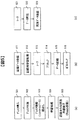
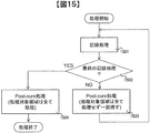
図15を用いて本実施例における記録処理とポストキュア処理のフローを説明する。ステップ1501、1502、1503を1つのサイクルとして記録終了までこのサイクルを回す。
ステップ1501では、所定の範囲の記録処理が行われる。この範囲は前述したように一意には決まらず設計事項となる。
記録処理終了後、ステップ1502で最終の記録処理かどうかの判定を行う。
ステップ1502でNOと判定されれば、ステップ1503でポストキュア処理が行われる。ここでのポストキュア処理は、ステップ1501で記録処理した領域を全てポストキュア処理せず、一部を残した処理となる。
N+1(Nは自然数)サイクル目のポストキュア処理は、Nサイクル目のポストキュア処理で残したポストキュア対象領域のポストキュアも同時に行う。またN+1サイクル目の処理における、「ステップ1501の記録処理に必要な時間」と、「ステップ1503のNステップ目で、未処理で残されているポストキュア対象領域Sの処理に必要な時間」を足した時間が、ポストキュア対象領域Sの領域のポストキュアタイムアウト時間を越えないようにする必要がある。なお、ステップ1502の判断時間は無視できる時間と見なしてここでは考慮しない。
また、Nサイクル目のステップ1503のポストキュア処理は、N+1サイクル目の記録処理の対象領域である未記録領域において図8、図9のようなダメージ領域が未記録領域に発生しないように処理を行う必要がある。YESと判定されれば、ステップ1504でポストキュア処理が行われるが、ここでのポストキュア処理は、ステップ1503とは異なり、ステップ1501の記録処理領域を全て処理し、ポストキュア未処理の領域を残さない。
以上、本実施例では同心円単位で記録することを例に説明したが、同心円単位の記録に限定されるものではなく、他の記録単位でも適応可能である。
図16は、記録処理単位が同心円単位ではない場合を示している。例えば図16(a)ように、8等分した扇形の単位で記録を行う場合、本発明を適応しない場合は、図16(b)のように同心円状にダメージ領域が発生してしまうが、本発明を適応することで、図16(c)のように同心円状のダメージ領域の発生を防ぐことができ、記録媒体の記録容量低下を抑制可能である。また、記録媒体の形状も円盤に限定されず方形の記録媒体でも適応可能である。
なお、本発明は上記した実施例に限定されるものではなく、様々な変形例が含まれる。例えば、上記した実施例は本発明を分かりやすく説明するために詳細に説明したものであり、必ずしも説明した全ての構成を備えるものに限定されるものではない。また、ある実施例の構成の一部を他の実施例の構成に置き換えることが可能であり、また、ある実施例の構成に他の実施例の構成を加えることも可能である。また、各実施例の構成の一部について、他の構成の追加・削除・置換をすることが可能である。
変形例としては例えば以下の例がある。
第一の変形例として、記録媒体に信号光と参照光を照射してホログラムを形成することで情報を記録し、該情報を再生する情報記録再生装置であって、レーザ光を出射するレーザ光源と、前記信号光と前記参照光を前記記録媒体に照射して情報を記録する光ピックアップと、前記記録媒体に情報を記録した後に、該情報を記録した既記録領域に前記レーザ光を照射するポストキュア処理を行うキュア光学部と、を備え、前記キュア光学部がポストキュア処理を施したポストキュア処理領域は、前記既記録領域に包含され、かつ、該既記録領域より小さい範囲ある、情報記録再生装置がある。
第二の変形例として、記録媒体に信号光と参照光を照射してホログラムを形成することで情報を記録し、該情報を再生する情報記録再生方法であって、レーザ光を出射するレーザ光出射ステップと、前記信号光と前記参照光を前記記録媒体に照射して情報を記録する記録ステップと、前記記録媒体に情報を記録した後に、該情報を記録した既記録領域に前記レーザ光を照射するポストキュア処理を行うポストキュア処理ステップと、を備え、前記ポストキュア処理ステップでは、ポストキュア処理を施したポストキュア処理領域は、前記既記録領域に包含され、かつ、該既記録領域より小さい範囲ある、情報記録再生方法がある。
また、上記の各構成、機能、処理部、処理手段等は、それらの一部又は全部を、例えば集積部で設計する等によりハードウェアで実現してもよい。また、上記の各構成、機能等は、プロセッサがそれぞれの機能を実現するプログラムを解釈し、実行することによりソフトウェアで実現してもよい。各機能を実現するプログラム、テーブル、ファイル等の情報は、メモリや、ハードディスク、SSD(Solid State Drive)等の記録装置、または、ICカード、SDカード等の記録媒体に置くことができる。
また、制御線や情報線は説明上必要と考えられるものを示しており、製品上必ずしも全ての制御線や情報線を示しているとは限らない。実際には殆ど全ての構成が相互に接続されていると考えてもよい。
1・・・記録媒体、10・・・データ記録再生装置、11・・・ピックアップ、
12・・・再生用参照光光学系、13・・・媒体キュア光学系、
14・・・媒体回転角度検出用光学系、81・・・アクセス制御部、
82・・・光源駆動部、83・・・サーボ信号生成部、
84・・・サーボ制御部、85・・・信号処理部、86・・・信号生成部、
87・・・シャッタ制御部、88・・・媒体回転モータ制御部、
89・・・コントローラ、90…入出力制御部、91・・・制御装置、
12・・・再生用参照光光学系、13・・・媒体キュア光学系、
14・・・媒体回転角度検出用光学系、81・・・アクセス制御部、
82・・・光源駆動部、83・・・サーボ信号生成部、
84・・・サーボ制御部、85・・・信号処理部、86・・・信号生成部、
87・・・シャッタ制御部、88・・・媒体回転モータ制御部、
89・・・コントローラ、90…入出力制御部、91・・・制御装置、
Claims (18)
- 記録媒体に信号光と参照光を照射してホログラムを形成することで情報を記録し、該情報を再生する情報記録再生装置であって、
レーザ光を出射するレーザ光源と、
前記信号光と前記参照光を前記記録媒体に照射して情報を記録する光ピックアップと、
前記記録媒体に情報を記録した後に、該情報を記録した既記録領域に前記レーザ光を照射するポストキュア処理を行うキュア光学部と、
を備え、
前記キュア光学部がポストキュア処理を施したポストキュア処理領域は、前記既記録領域に包含され、かつ、該既記録領域より小さい範囲である、
情報記録再生装置。 - 請求項1に記載の情報記録再生装置であって、
前記キュア光学部は、前記既記録領域の一部をポストキュアが未処理であるポストキュア未処理領域としてポストキュア処理をする、情報記録再生装置。 - 請求項2に記載の情報記録再生装置であって、
前記記録媒体に情報を記録し、前記既記録領域にポストキュア処理を行う工程を1サイクルとし、該工程を繰り返しながら情報を該記録媒体に記録する場合、
前記キュア光学部は、第一のサイクルのポストキュア未処理領域を、第二のサイクルでポストキュア処理する、
ことを特徴とする情報記録再生装置。 - 請求項2に記載の情報記録再生装置であって、
前記記録媒体に情報を記録し、前記既記録領域にポストキュア処理を行う工程を1サイクルとし、該工程を繰り返しながら情報を該記録媒体に記録する場合、
前記キュア光学部は、Nサイクル(Nは自然数)のポストキュア未処理領域を、N+1サイクルでポストキュア処理する、
ことを特徴とする情報記録再生装置。 - 請求項4に記載の情報記録再生装置であって、
前記既記録領域への情報の記録終了後から、該既記録領域のポストキュア処理を完了するまでの時間の制限であるポストキュア制限時間がある場合、
前記光ピックアップおよび前記ポストキュア光学部は、前記Nサイクル目のポストキュア未処理領域のポストキュア処理に必要な時間と、前記N+1サイクル目に情報を記録する時間と、を足し合わせた時間が、前記ポストキュア制限時間を超えないように記録およびポストキュア処理を行う、
ことを特徴とする情報記録再生装置。 - 請求項2に記載の情報記録再生装置であって、
前記キュア光学部は、前記ポストキュア処理領域と、該ポストキュア処理領域に隣接する所定の領域と、を合わせた領域が、前記既記録領域より小さくなるように前記ポストキュア処理を行う、
ことを特徴とする情報記録再生装置。 - 請求項2に記載の情報記録再生装置であって、
前記記録媒体を回転または静止させる記録媒体駆動部を備え、
前記記録媒体駆動部は、情報を前記記録媒体に記録する場合は、該記録媒体を静止させ、前記ポストキュア処理をする場合は、該記録媒体を回転させるようを制御する、
ことを特徴とする情報記録再生装置。 - 請求項2に記載の情報記録再生装置であって、
前記既記録領域および前記ポストキュア処理領域は、前記記録媒体に同心円状に形成されること、
を特徴とする情報記録再生装置。 - 請求項8に記載の情報記録再生装置であって、
前記既記録領域が前記記録媒体の内周から外周に向かって同心円状に形成された場合、前記ポストキュア処理領域は該記録媒体の内周から外周に向かって同心円状に形成され、
前記既記録領域が前記記録媒体の外周から内周に向かって同心円状に形成された場合、前記ポストキュア処理領域は該記録媒体の外周から内周に向かって同心円状に形成される、
ことを特徴とする情報記録再生装置。 - 記録媒体に信号光と参照光を照射してホログラムを形成することで情報を記録し、該情報を再生する情報記録再生方法であって、
レーザ光を出射するレーザ光出射ステップと、
前記信号光と前記参照光を前記記録媒体に照射して情報を記録する記録ステップと、
前記記録媒体に情報を記録した後に、該情報を記録した既記録領域に前記レーザ光を照射するポストキュア処理を行うポストキュア処理ステップと、
を備え、
前記ポストキュア処理ステップでは、ポストキュア処理を施したポストキュア処理領域は、前記既記録領域に包含され、かつ、該既記録領域より小さい範囲である、
情報記録再生方法。 - 請求項10に記載の情報記録再生方法であって、
前記ポストキュア処理ステップでは、前記既記録領域の一部をポストキュアが未処理であるポストキュア未処理領域としてポストキュア処理をする、情報記録再生方法。 - 請求項11に記載の情報記録再生方法であって、
前記記録媒体に情報を記録し、前記既記録領域にポストキュア処理を行う工程を1サイクルとし、該工程を繰り返しながら情報を該記録媒体に記録する場合、
前記ポストキュア処理ステップでは、第一のサイクルのポストキュア未処理領域を、第二のサイクルでポストキュア処理する、
ことを特徴とする情報記録再生方法。 - 請求項11に記載の情報記録再生方法であって、
前記記録媒体に情報を記録し、前記既記録領域にポストキュア処理を行う工程を1サイクルとし、該工程を繰り返しながら情報を該記録媒体に記録する場合、
前記ポストキュア処理ステップでは、Nサイクル(Nは自然数)のポストキュア未処理領域を、N+1サイクルでポストキュア処理する、
ことを特徴とする情報記録再生方法。 - 請求項13に記載の情報記録再生方法であって、
前記既記録領域への情報の記録終了後から、該既記録領域のポストキュア処理を完了するまでの時間の制限であるポストキュア制限時間がある場合、
前記記録ステップおよびポストキュア処理ステップでは、前記Nサイクル目のポストキュア未処理領域のポストキュア処理に必要な時間と、前記N+1サイクル目に情報を記録する時間と、を足し合わせた時間が、前記ポストキュア制限時間を超えないように記録およびポストキュア処理を行う、
ことを特徴とする情報記録再生方法。 - 請求項11に記載の情報記録再生方法であって、
前記ポストキュア処理ステップでは、前記ポストキュア処理領域と、該ポストキュア処理領域に隣接する所定の領域と、を合わせた領域が、前記既記録領域より小さくなるように前記ポストキュア処理を行うこと、
を特徴とする情報記録再生方法。 - 請求項11に記載の情報記録再生方法であって、
前記記録媒体を回転または静止させる記録媒体駆動ステップを備え、
記録媒体駆動ステップでは、情報を前記記録媒体に記録する場合は、該記録媒体を静止させ、前記ポストキュア処理をする場合は、該記録媒体を回転させる、
ことを特徴とする情報記録再生方法。 - 請求項11に記載の情報記録再生方法であって、
前記記録ステップおよびポストキュア処理ステップでは、前記既記録領域および前記ポストキュア処理領域は、前記記録媒体に同心円状に形成されること、
を特徴とする情報記録再生方法。 - 請求項17に記載の情報記録再生方法であって、
前記記録ステップおよびポストキュア処理ステップでは、
前記既記録領域が前記記録媒体の内周から外周に向かって同心円状に形成された場合、前記ポストキュア処理領域は該記録媒体の内周から外周に向かって同心円状に形成され、
前記既記録領域が前記記録媒体の外周から内周に向かって同心円状に形成された場合、前記ポストキュア処理領域は該記録媒体の外周から内周に向かって同心円状に形成される、
ことを特徴とする情報記録再生方法。
Priority Applications (1)
| Application Number | Priority Date | Filing Date | Title |
|---|---|---|---|
| PCT/JP2014/055001 WO2015129016A1 (ja) | 2014-02-28 | 2014-02-28 | 情報記録再生装置および情報記録方法 |
Applications Claiming Priority (1)
| Application Number | Priority Date | Filing Date | Title |
|---|---|---|---|
| PCT/JP2014/055001 WO2015129016A1 (ja) | 2014-02-28 | 2014-02-28 | 情報記録再生装置および情報記録方法 |
Publications (1)
| Publication Number | Publication Date |
|---|---|
| WO2015129016A1 true WO2015129016A1 (ja) | 2015-09-03 |
Family
ID=54008382
Family Applications (1)
| Application Number | Title | Priority Date | Filing Date |
|---|---|---|---|
| PCT/JP2014/055001 WO2015129016A1 (ja) | 2014-02-28 | 2014-02-28 | 情報記録再生装置および情報記録方法 |
Country Status (1)
| Country | Link |
|---|---|
| WO (1) | WO2015129016A1 (ja) |
Citations (7)
| Publication number | Priority date | Publication date | Assignee | Title |
|---|---|---|---|---|
| JP2007058992A (ja) * | 2005-08-24 | 2007-03-08 | Fujifilm Corp | 光記録方法、光記録装置、光記録媒体及び光記録再生方法 |
| US7557971B1 (en) * | 2006-03-10 | 2009-07-07 | StorageTek Technology Corporation | System and method for managing multiple write sessions to holographic storage media |
| JP2009289384A (ja) * | 2008-06-02 | 2009-12-10 | Hitachi Ltd | 光情報記録再生装置及び光情報記録方法 |
| JP2009301627A (ja) * | 2008-06-12 | 2009-12-24 | Hitachi Ltd | 光情報記録装置および光情報記録方法 |
| JP2010044825A (ja) * | 2008-08-13 | 2010-02-25 | Hitachi Ltd | 光情報記録/再生装置 |
| JP2010181760A (ja) * | 2009-02-09 | 2010-08-19 | Hitachi Ltd | 光情報記録方法および記録装置 |
| WO2014033895A1 (ja) * | 2012-08-31 | 2014-03-06 | 日立コンシューマエレクトロニクス株式会社 | ホログラム記録装置及びホログラム記録方法 |
-
2014
- 2014-02-28 WO PCT/JP2014/055001 patent/WO2015129016A1/ja active Application Filing
Patent Citations (7)
| Publication number | Priority date | Publication date | Assignee | Title |
|---|---|---|---|---|
| JP2007058992A (ja) * | 2005-08-24 | 2007-03-08 | Fujifilm Corp | 光記録方法、光記録装置、光記録媒体及び光記録再生方法 |
| US7557971B1 (en) * | 2006-03-10 | 2009-07-07 | StorageTek Technology Corporation | System and method for managing multiple write sessions to holographic storage media |
| JP2009289384A (ja) * | 2008-06-02 | 2009-12-10 | Hitachi Ltd | 光情報記録再生装置及び光情報記録方法 |
| JP2009301627A (ja) * | 2008-06-12 | 2009-12-24 | Hitachi Ltd | 光情報記録装置および光情報記録方法 |
| JP2010044825A (ja) * | 2008-08-13 | 2010-02-25 | Hitachi Ltd | 光情報記録/再生装置 |
| JP2010181760A (ja) * | 2009-02-09 | 2010-08-19 | Hitachi Ltd | 光情報記録方法および記録装置 |
| WO2014033895A1 (ja) * | 2012-08-31 | 2014-03-06 | 日立コンシューマエレクトロニクス株式会社 | ホログラム記録装置及びホログラム記録方法 |
Similar Documents
| Publication | Publication Date | Title |
|---|---|---|
| JP4881914B2 (ja) | 光情報記録再生装置及び光情報記録方法 | |
| JP5581111B2 (ja) | 光情報再生装置および光情報再生方法 | |
| US9013972B2 (en) | Optical information recording and reproducing method and device | |
| US8699311B2 (en) | Optical information recording/reproducing apparatus, optical information reproducing apparatus, optical information recording/reproducing method and optical information reproducing method | |
| JP5104695B2 (ja) | 情報記録装置 | |
| WO2015129016A1 (ja) | 情報記録再生装置および情報記録方法 | |
| US9373352B2 (en) | Optical information reproduction apparatus and optical information reproduction method | |
| US20170162221A1 (en) | Optical Information Recording/Reproduction Device and Optical Information Recording/Reproduction Method | |
| JP5211816B2 (ja) | 光情報記録再生装置 | |
| JP2012221520A (ja) | 光情報再生装置、光情報記録再生装置 | |
| US8144557B2 (en) | Optical information recording/reproducing apparatus and disk distinction method | |
| JP2010198707A (ja) | 信号品質評価装置、信号品質評価方法、および情報記録媒体 | |
| US20150131424A1 (en) | Optical information recording/reproduction device, recording condition adjustment method, and optical information recording medium | |
| WO2016163312A1 (ja) | 光情報再生装置及び光情報再生方法 | |
| JP6078634B2 (ja) | 光情報再生装置および光情報記録再生装置 | |
| WO2015162724A1 (ja) | データ記録方法及びデータ記録装置 | |
| JP2015082327A (ja) | 光情報再生装置、光情報再生方法および光情報記録方法 | |
| WO2016199229A1 (ja) | ホログラム記録再生装置 | |
| JP5647965B2 (ja) | 光情報記録再生装置、光情報記録装置、光情報記録再生方法、光情報記録媒体 | |
| US20160358623A1 (en) | Optical information recording/reproducing device and optical information recording/reproducing method | |
| WO2014073042A1 (ja) | 情報記録再生装置、およびそれを用いた記録方法 | |
| JP2016201156A (ja) | ホログラム記録装置及びホログラム記録方法 | |
| WO2016135941A1 (ja) | 記録情報量の判定方法およびそれを用いた光情報記録再生装置 | |
| WO2013175526A1 (ja) | 光情報再生装置及び光情報再生方法 | |
| JP2011187101A (ja) | 光情報記録再生装置、及び光情報再生方法 |
Legal Events
| Date | Code | Title | Description |
|---|---|---|---|
| 121 | Ep: the epo has been informed by wipo that ep was designated in this application |
Ref document number: 14883671 Country of ref document: EP Kind code of ref document: A1 |
|
| NENP | Non-entry into the national phase |
Ref country code: DE |
|
| 122 | Ep: pct application non-entry in european phase |
Ref document number: 14883671 Country of ref document: EP Kind code of ref document: A1 |
|
| NENP | Non-entry into the national phase |
Ref country code: JP |