WO2015128996A1 - 停止用板バネ成形機 - Google Patents
停止用板バネ成形機 Download PDFInfo
- Publication number
- WO2015128996A1 WO2015128996A1 PCT/JP2014/054922 JP2014054922W WO2015128996A1 WO 2015128996 A1 WO2015128996 A1 WO 2015128996A1 JP 2014054922 W JP2014054922 W JP 2014054922W WO 2015128996 A1 WO2015128996 A1 WO 2015128996A1
- Authority
- WO
- WIPO (PCT)
- Prior art keywords
- mandrel
- leaf spring
- stop
- processed
- punch
- Prior art date
- Legal status (The legal status is an assumption and is not a legal conclusion. Google has not performed a legal analysis and makes no representation as to the accuracy of the status listed.)
- Ceased
Links
Images





Classifications
-
- B—PERFORMING OPERATIONS; TRANSPORTING
- B21—MECHANICAL METAL-WORKING WITHOUT ESSENTIALLY REMOVING MATERIAL; PUNCHING METAL
- B21D—WORKING OR PROCESSING OF SHEET METAL OR METAL TUBES, RODS OR PROFILES WITHOUT ESSENTIALLY REMOVING MATERIAL; PUNCHING METAL
- B21D22/00—Shaping without cutting, by stamping, spinning, or deep-drawing
- B21D22/20—Deep-drawing
- B21D22/26—Deep-drawing for making peculiarly, e.g. irregularly, shaped articles
-
- B—PERFORMING OPERATIONS; TRANSPORTING
- B21—MECHANICAL METAL-WORKING WITHOUT ESSENTIALLY REMOVING MATERIAL; PUNCHING METAL
- B21D—WORKING OR PROCESSING OF SHEET METAL OR METAL TUBES, RODS OR PROFILES WITHOUT ESSENTIALLY REMOVING MATERIAL; PUNCHING METAL
- B21D22/00—Shaping without cutting, by stamping, spinning, or deep-drawing
- B21D22/02—Stamping using rigid devices or tools
- B21D22/06—Stamping using rigid devices or tools having relatively-movable die parts
Definitions
- the present invention relates to a stop leaf spring forming machine for forming a stop leaf spring of a slider for a slide fastener with an automatic stop device.
- a stop leaf spring forming machine for forming a stop leaf spring for a slide fastener slider
- a mandrel whose outer peripheral surface matches the shape of the stop leaf spring and a plurality of punches provided around the mandrel are provided.
- a molding machine that forms a stop leaf spring by moving a plurality of punches toward a mandrel and bending a linear material along the outer peripheral surface of the mandrel.
- the predetermined arc shape may not be obtained.
- the present invention has been made in order to solve the above-mentioned problems, and its object is to make it possible to appropriately bend a stop leaf spring having a curved portion with a small-diameter arc shape. It is a leaf spring forming machine.
- the present invention is a molding machine for molding a leaf spring 10 for stopping a slider for a slide fastener
- the molding machine includes a mandrel 3c and a plurality of punches provided around the mandrel 3c.
- the material is bent along the outer peripheral surface of the mandrel 3c by moving the punch toward the mandrel 3c, and formed into a stop leaf spring 10,
- the stopping leaf spring 10 has a bending portion 11, one side portion 12 continuous with one end portion of the bending portion 11, and another side portion 13 continuous with the other end portion of the bending portion 11,
- the mandrel 3c is provided with a processing portion for forming a material into the stop leaf spring 10, and the processing portion includes a one side processing surface for bending the one side portion 12 of the stop leaf spring 10 and the other side portion 13.
- the punch is a stopping leaf spring molding machine that bends the one side portion 12 and the other side portion 13 of the stopping leaf spring 10 by bending the material along the processing surface of the processing portion of the man
- the leaf spring molding machine for stop includes a mandrel 3c and a mandrel holder 3a, and the mandrel 3c reciprocates through a mandrel insertion hole 3b of the mandrel holder 3a.
- the processing portion of the mandrel 3c may include a first processing portion 3c-1 and a second processing portion 35 for forming the stop leaf spring 10.
- the stop leaf spring can be continuously processed from the material easily and sequentially by changing the position of the mandrel 3c. Can do.
- the mandrel 3c includes the first processing unit 3c-1 and a second processing unit 35 protruding from the first processing unit 3c-1 in the moving direction of the mandrel 3c,
- the mandrel 3c is movable to a position where the machining surface of the first machining portion 3c-1 faces the punch, and a position where the machining surface of the second machining portion 35 faces the punch, A state in which the stop leaf spring 10 is bent along the processed surface of the first processed portion 3c-1 of the mandrel 3c, and the stop leaf spring 10 is bent along the processed surface of the second processed portion 35 of the mandrel 3c.
- the position of the mandrel 3c can be switched to the state to be processed.
- the first processed portion is bent to form the curved surface diameter, and the curved surface formed by the first processed portion can be continuously bent to a smaller size than the second processed portion.
- the stop leaf spring can be appropriately bent.
- the mandrel 3c moves through the mandrel insertion hole 3b of the mandrel holder 3a, A forward position where the first processing portion 3c-1 and the second processing portion 35 of the mandrel 3c protrude from the mandrel insertion hole 3b; A first retracted position in which the second processing portion 35 protrudes from the mandrel insertion hole 3b and the first processing portion 3c-1 is submerged in the mandrel insertion hole 3b; In the mandrel insertion hole 3b, the mandrel 3c can be moved to the second retracted position in which the first processed portion 3c-1 and the second processed portion 35 are submerged.
- the leaf spring forming machine for a stop includes a material supply unit that continuously supplies a long material 15 toward the one-side processed surface of the mandrel 3c,
- the molding machine can be provided with a punch for cutting the long material 15.
- the stop leaf spring can be continuously formed using the long material 15.
- the stop plate spring molding machine of the present invention is provided with a discharge portion 6 for discharging the stop plate spring 10 formed by the mandrel 3c and the punch.
- a gas blowing means for blowing gas along the processed surface of the mandrel 3c and a negative pressure generating means for making the discharge portion 6 a negative pressure can be provided.
- the stop plate spring formed by the mandrel 3c and the punch when discharged from the discharge portion of the molding machine, the stop plate spring may be clogged in the discharge portion by allowing gas to flow into the discharge portion. Absent.
- the molding machine is provided with a discharge portion 6 continuous with the mandrel insertion hole 3b, Forming an air nozzle 46 through which gas flows between the mandrel 3c and the mandrel insertion hole 3b;
- a gas is supplied to the air nozzle 46 from the gas supply unit 8 provided in the molding machine, and a gas blowing means is formed by the gas supply unit 8 and the air nozzle 46,
- a gas ejection hole 63 for ejecting gas can be provided in the discharge part 6 to serve as the negative pressure generating means.
- the discharge portion 6 provided in the molding machine includes a first cylinder 60 and a second cylinder 62, and the first cylinder 60 communicates with the second cylinder 62. It is possible to change the posture between a state where the second cylinder 62 is in communication and a state where the second cylindrical body 62 is not in communication.
- the material used for the stop leaf spring is bent together with the punch along the outer peripheral surface of the mandrel 3c, the material is bent, and one side portion 12 continuous to one end of the bending portion, It can be processed into the stopping spring 10 having the other side portion 13 continuous with the other end portion of the bending portion.
- the processed portion provided on the outer peripheral surface of the mandrel 3c includes a one-side processed surface and an other-side processed surface, and after the material is curved by the one-side processed surface, the other-side processed surface, and the punch, The side part 12 and the other side part 13 can be processed continuously.
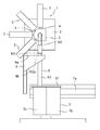
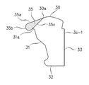
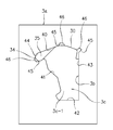
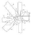
- FIG. 1 It is a schematic side view of the leaf spring molding machine for a stop which shows the embodiment of the present invention. It is a schematic front view of the leaf spring molding machine for a stop which shows the embodiment of the present invention. It is an expanded sectional view of a mandrel part. It is a side view of a leaf spring for a stop. It is a perspective view of a mandrel and a mandrel holder. It is sectional drawing of the main part of a mandrel. It is sectional drawing of the protrusion of a mandrel. It is a front view of the state which attached the mandrel to the mandrel holder. It is a front view of a mandrel and a punch. It is explanatory drawing of the movement of a mandrel. FIG. FIG. FIG. FIG. FIG.
- the stop leaf spring forming machine 1 is a main body 2 of a stop leaf spring forming machine 1 attached to a frame (not shown).
- a mandrel part 3 attached to the main body part 2, a plurality of punches 4 provided around the mandrel part 3, a punch moving part 5 for reciprocating each punch 4 toward the mandrel part 3, and a mandrel part 3
- the discharge part 6 for discharging the stop plate spring formed in step 1, the storage part 7 for storing the stop plate spring discharged from the discharge part 6, and the air blown to the stop plate spring formed by the mandrel part 3
- An air supply unit 8 is provided.
- the accommodating portion 7 includes a plurality of accommodating boxes 7b that are movable along the guide 7a. The storage box 7b is moved when one storage box 7b is full, and the stop leaf spring is stored in the other storage box 7b. If it does in this way, the leaf
- a defective product discharge chute 9 is provided.
- the defective stop leaf spring can be discharged to a container or the like separate from the housing portion 7 by the defective product discharge chute 9.
- the discharge part 6 includes a first cylinder 60 that is swingably attached to the mandrel part 3 and a second cylinder 62 that communicates with a hole in the plate 61 that is slidably in contact with the storage box 7b. .
- the first cylinder 60 projects inward from the upper surface 9 a of the defective product discharge chute 9, and the second cylinder 62 projects inward from the lower surface 9 b of the defective product discharge chute 9.
- the first cylinder 60 communicates with the second cylinder 62 in the defective product discharge chute 9 and the defective product discharge attitude opens in the defective product discharge chute 9 without communicating with the second cylinder 62.
- the lower end portion of the first cylinder 60 projects into the defective product discharge chute 9 from a long hole formed in the upper surface 9 a of the defective product discharge chute 9, and the second cylinder 62 has a larger diameter than the first cylinder 60.
- the upper end portion of the second cylindrical body 62 protruding into the defective product discharge chute 9 is cut out at a part of its peripheral surface, and the lower end portion of the first cylindrical body 60 extends from the notched portion 62a to the second cylinder.
- the first cylindrical body 60 and the second cylindrical body 62 are not limited to a circular cross section, and may be square or rectangular, and the first cylindrical body 60 enters the second cylindrical body 62 or the first cylindrical body 60. What is necessary is just to be in the state which the 2nd cylinder 62 communicates.
- the lower end part of the 1st cylinder 60 is the 2nd by making the 1st cylinder 60 swing by a cylinder, a motor, or manual operation, and setting it as the good product discharge posture shown as a solid line in FIG.
- the first cylindrical body 60 and the second cylindrical body 62 are continuous through the cutout portion 62a of the cylindrical body 62, and the non-defective stop spring is discharged and stored in the storage box 7b of the storage section 7. .
- the lower end portion of the first cylinder 60 is cut off from the second cylinder 62. It comes out of the notch portion 62a and opens to the defective product discharge chute 9 without communicating with the second cylindrical body 62, and the stop leaf spring as a defective product is discharged from the defective product discharge chute 9 to a defective product reservoir not shown. .
- the mandrel part 3 for forming the material includes a mandrel holder 3 a attached to the main body part 2, a mandrel 3 c movably inserted into a mandrel insertion hole 3 b of the mandrel holder 3 a, and a punch 4.
- a cover body 3d provided on the opposite side of the mandrel holder 3a is provided, and the punch 4 moves between the mandrel holder 3a and the cover body 3d.
- the cover body 3d has a discharge space 3d-1 facing the mandrel 3c and continuing to the mandrel insertion hole 3b.
- the main body 2 has a through hole 20 continuous with the mandrel insertion hole 3 b and an air supply hole 21 communicating with the through hole 20.
- An air supply unit 8 for example, an air supply pipe, is continuous with the air supply hole 21 of the main body 2.
- a moving rod 22 is slidably fitted in the through hole 20.
- the moving rod 22 reciprocates in the direction of the arrow along the through-hole 20 by a moving mechanism (not shown), and the forward position a indicated by a solid line in FIG. 3, the backward position b indicated by a one-dot chain line, and the last retracted position c indicated by a two-dot chain line. Move to.
- the mandrel 3c connected to the moving rod 22 moves to the forward movement position, the backward movement position, and the last backward movement position.
- the rotating cam is used as the moving mechanism, it is not limited to this.
- the air supply unit 8 supplies air to the air supply hole 21 at the same timing as the end of the forming operation of the stop leaf spring.
- a switching valve is provided in the middle of the air supply pipe, and the switching valve is in communication with the end of the molding operation to supply air. Air supplied to the through-hole 20 is blown toward the discharge portion 6 along the processed surface of the mandrel 3c by an air nozzle described later, and air is blown to the formed stop plate spring to cover the stop plate spring. Blow away into 3d discharge space 3d-1.
- the discharge part 6 communicates with the discharge space 3d-1 of the cover body 3d.
- the upper end portion (one end portion) of the first cylindrical body 60 is swingably attached to the cover body 3d via a rotating means such as a bearing.
- the first cylinder body 60 is rotatably attached to the cover body 3d.
- the discharge part 6 is set to a negative pressure by the negative pressure generating means, sucks the air in the discharge space 3d-1 of the cover body 3d and discharges it to the outside.
- the negative pressure generating means includes a cylindrical body 64 having an air ejection hole 63 in the middle of the first cylindrical body 60, and ejects air from the air ejection hole 63 in the discharge direction, thereby forming the cover body 3d.
- the air in the discharge space 3d-1 is sucked into a negative pressure.
- the air used in the air supply unit 8 and the negative pressure generating means is not limited to air, and may be an inert gas such as nitrogen gas or a gas such as a mixed gas of air and other gases.
- the moving rod 22 is moved to the last retracted position c, and from the air supply unit 8 toward the first cylindrical body 60.
- air is blown toward the stop leaf spring attached to the mandrel 3c, and the discharge space 3d- Since the air in 1 is sucked in, the molded stop leaf spring can be reliably discharged.
- a stop plate spring formed by the stop plate spring forming machine of this embodiment will be described with reference to FIG.
- the direction going to the left and right will be described as the left and right direction
- the direction going up and down will be described as the up and down direction.
- the stop leaf spring 10 is continuous with the arcuate curved part 11 on one side in the left-right direction that is curved in the vertical direction, and the one end 11a above the arcuate curved part 11, and is directed to the other side in the left-right direction.
- the one side portion 12 and the other end portion 11b below the arcuate curved portion 11 are continuous with each other and the other side portion 13 facing the other side in the left-right direction is substantially U-shaped.
- One side portion 12 above the stopping leaf spring 10 is continuous with one end portion 11a of the arcuate curved portion 11 and has a linear base end portion 12a extending in the left-right direction, and is connected to the base end portion 12a in an arc shape.
- An intermediate curved portion 12b that is curved in a straight line and a tip portion 12c that is continuous with the intermediate curved portion 12b and bent substantially vertically downwardly have a substantially gentle mountain shape.
- the other side portion 13 below the stop leaf spring 10 is continuous with the other end portion 11b of the arcuate curved portion 11, and is a linear base end portion substantially parallel to the base end portion 12a of the one side portion 12.
- 13a, a linear intermediate portion 13b which is continuous with the base end portion 13a and is bent downward, and a linear distal end portion 13c which is continuous with the intermediate portion 13b and is bent downward are provided with two apexes.
- the distal end of the distal end portion 13 c is a stop claw 14.
- the mandrel 3c for forming and processing the material 15 into the stop leaf spring 10 includes a main part 3c-1 and a main part that reciprocate in the longitudinal direction of the mandrel insertion hole 3b of the mandrel holder 3a. It has a protrusion 35 protruding in the longitudinal direction from the end face of 3c-1.
- the mandrel 3c has a first processed part and a second processed part for forming the plate-shaped material 15 into the stop leaf spring 10, and a main part 3c-1 as a first processed part and a protrusion as a second processed part.
- the material 15 is deformed stepwise by 35 and molded.
- the mandrel 3c that forms and processes the material 15 into the stop leaf spring 10 has an upper surface 30 that is a processed surface on one side, a lateral surface 31 that is a processed surface on the other side, a lower surface 32, A main body 3c-1 having an outer peripheral surface surrounded by the other side surface 33 in the direction is provided.
- the upper surface 30 of the main portion 3c-1 of the mandrel 3c has the same shape as the one side portion 12 above the stop leaf spring 10.
- the upper surface 30 on the outer peripheral surface thereof is an upper surface 30a at one end, an intermediate upper surface 30b that is continuous with the upper surface 30a of the one end, and a lower surface 32 that is continuous with the upper surface 30a of the intermediate portion.
- the other end upper surface 30c is vertically extended downward and has an L shape.
- the upper side 30 of the main portion 3c-1 of the mandrel 3c bends the one side portion 12 above the stop leaf spring 10.
- the upper surface 30 of the main body portion 3c-1 serves as a one-side processed surface for pressing and processing the one side portion 12 above the stop plate spring 10.
- the upper surface 30 and one side surface 31 of the main body portion 3c-1 are continuous with an arcuate curved surface 34, and the arcuate curved surface 34 has a diameter larger than the diameter of the arcuate curved portion 11 of the stopping leaf spring 10. .
- One side surface 31 of the main portion 3c-1 of the mandrel 3c has substantially the same shape as the other side portion 13 below the stopping leaf spring 10.
- One side surface 31 on the side surface of the main portion 3c-1 serves as an other side processing surface that presses and processes the other side portion 13 below the stopping leaf spring 10. That is, one side surface 31 that is continuous with the arcuate curved surface 34 includes a concave surface 31a that is recessed toward the upper surface 30, a first side surface 31b that is continuous with the lower end of the concave surface 31a and that faces the lower surface 32, and the first side surface 31b.
- the stop side spring 10 includes the side surface 31 f indicated by a virtual line that continues the arcuate curved surface 34 and the first side surface 31 b, the first side surface 31 b, the second side surface 31 c, and the third side surface 31 d. It has the same shape as the other side portion 13.
- the one side surface 31 has the same shape as a part of the linear base end portion 13a in the other side portion 13 of the stopping leaf spring 10 that is recessed upward.
- the length of the third side surface 31d is shorter than the length of the tip portion 13c of the other side portion 13 of the stop leaf spring 10.
- the lower surface 32 and the other side surface 33 each form a straight flat surface, and form an angle of 90 ° and are continuous.
- the diameter of the arcuate curved surface 34 of the main part 3c-1 of the mandrel 3c is larger than the diameter of the arcuate curved part 11 of the stop leaf spring 10.
- the mandrel 3c has a protrusion 35 on the end surface in the longitudinal direction of the main body 3c-1.
- the projection 35 of the mandrel 3c includes an upper surface 35a that extends continuously in the longitudinal direction from one end upper surface 30a on the upper surface 30 of the main body 3c-1, and an arcuate curved surface of the main body 3c-1. 34, a curved surface 35b that is continuous in the longitudinal direction, and a lower surface 35c that is continuous with the concave surface 31a and the upper surface 30a at one end and extends in the longitudinal direction.
- the upper surface 35a extending from the upper part of the arcuate curved surface 35b and the lower surface 35c extending from the lower part of the arcuate curved surface 35b are in contact. Thereby, the cross-sectional shape of the protrusion 35 in the longitudinal direction is substantially triangular.
- the diameter of the arcuate curved surface 35 b of the protrusion 35 is the same as the diameter of the arcuate curved part 11 of the stopping leaf spring 10.
- the upper surface 35a and the lower surface 35c intersect. That is, the upper surface 35a and the lower surface 35c of the protrusion 35 are not parallel.
- the diameter of the curved portion of the molded product formed by molding the material along the upper end surface 30a of the upper surface 30 of the main body 3c-1 and the first side surface 31b of the one side surface 31 is the circle of the stop leaf spring 10.
- a straight material larger than the diameter of the arcuate curved portion 11 is formed by the one end upper surface 30a of the upper surface 30 of the main body portion 3c-1 and the first side surface 31b of the one side surface 31, no crack is generated.
- the one side part in contact with the upper surface 30a of the protrusion 35 of the molded product formed along the protrusion 35 and the other side part in contact with the lower surface 3c of the protrusion 35 are closer to each other than parallel to each other. After molding, the one side and the other side are parallel by the spring back.
- the mandrel insertion hole 3b of the mandrel holder 3a is surrounded by the upper inner surface 40, the one inner surface 41, the lower surface 42, and the other inner surface 43 in the same manner as the outer peripheral surface of the main portion 3c-1 of the mandrel 3c.
- the upper inner surface 40 and the corner inner surface 44 connecting the upper inner surface 40 and the one-side inner surface 41 have recesses 45 respectively.
- the material supply part 3d is provided in the other side 33 side of the mandrel 3c.
- the material 15 is supplied toward the upper surface 30 of the mandrel 3c from the material supply passage 3e of the material supply unit 3d.
- the raw material 15 wound in a coil shape (not shown) is supplied.
- the material 15 is a long plate-like member made of a metal such as a stainless alloy.
- the punch 4 has four punches, a first punch 4a, a second punch 4b, a third punch 4c, a fourth pliers 4d, and a fifth punch 4e provided around the mandrel 3c, and these punches are placed on the mandrel 3c. 4 is formed by cutting the material 15 into a predetermined length by reciprocating toward the predetermined length and bending it.
- the 1st punch 4a moves to an up-down direction toward the intermediate part upper surface 30b and the other end upper surface 30c of the mandrel 3c.
- the second punch 4b moves in a diagonally upward and downward direction toward the upper surface 30a at one end of the mandrel 3c and the arcuate curved surface 34.
- the third punch 4c moves in the left-right direction toward the first side surface 31b, the second side surface 31c, and the third side surface 31d of the mandrel 3c.
- the fourth punch 4d moves obliquely up and down toward the lower surface 35c of the projection 35 of the mandrel 3c.
- the fifth punch 4e faces the first punch 4a in the vertical direction and moves in the vertical direction toward the first punch 4a.
- the main portion 3c-1 and the protrusion 35 of the mandrel 3c protrude larger in the longitudinal direction than the end surface of the mandrel holder 3a, and the upper surface of the main portion 3c-1 30 faces the punch 4.
- the material 15 is disposed between the upper surface 30 (outer peripheral surface) of the main body portion 3c-1 and the punch 4, and the upper surface 30 of the main body portion 3c-1 and the material 15 are in contact with each other.
- the punch 4 is moved toward the main portion 3c-1 of the mandrel 3c, and the material 15 is bent at the processing surface (outer peripheral surface) of the main portion 3c-1.
- the main portion 3c-1 of the mandrel 3c enters the mandrel insertion hole 3b of the mandrel holder 3a, and the projection 35 of the mandrel 3c is the end surface of the mandrel holder 3a. It protrudes more in the longitudinal direction, the upper surface 35 a of the protrusion 35 faces the punch 4, and the material 15 contacts the upper surface 35 a of the protrusion 35. As a result, the material 15 is bent at the processed surface (outer peripheral surface) of the protrusion 35.
- the punch moving unit 5 contacts the cam follower attached to the punch 4 with the rotating cam and rotates the cam to move the punch 4 toward the mandrel 3c or move away from the mandrel 3c. Moreover, it is not restricted to this, It is good also as an air cylinder.
- each punch is set at a standby position separated from the mandrel 3c, and the mandrel 3c having the main portion 3c-1 and the projection 35 moves through the mandrel insertion hole 3b of the mandrel holder 3a, and at the forward position a. It stops and the raw material 15 is supplied to the upper surface 30 of the main body part 3c-1. As a result, the material 15 is bent at the processed surface (outer peripheral surface) of the main portion 3c-1. At this time, the projection 35 of the mandrel 3c is positioned closer to the front than the material 15 as shown in FIG.
- the material 15 is supplied from the material supply part 3d to the front side of the mandrel holder 3a through the upper surface 30 of the main part 3c-1 of the mandrel 3c and the concave groove 50 of the second punch 4b until it reaches a predetermined length.
- the material supply unit 3d is provided with a material supply passage 3e, and the material 15 is supplied between the punch and the mandrel.
- the second punch 4b is moved obliquely downward, and the material 15 is moved to the upper end surface 30a of the one end portion of the mandrel 3c and the arcuate curved surface 34 by the bowl-shaped processed surface 51 of the second punch 4b. Press to bend into a V shape.
- the material 15 is a V-shaped first processed product 16 having one side portion 16 a of the material 15 and the other side portion 16 b of the end portion of the material 15 bent. In this way, the material 15 is processed and bent by the second punch 4b to become the processed product 16, and becomes the first processed product 16 as shown in FIG.
- the fifth punch 4e is moved upward in the above-described state, the first punch 4a is moved to the lower cutting position, and the downward projection 52 of the first punch 4a and the fifth punch 4e The material 15 is cut at the upper surface.
- the downward projecting portion 52 of the first punch 4a serves as a blade for cutting the material 15, and the upper portion of the fifth punch 4e serves as a blade receiving portion for receiving the blade.
- the fifth punch 4e is moved downward, and as shown in FIG. 13, the third punch 4c is moved so that the other side portion 16b of the first processed product 16 is the first side surface 31 of the one side 31 of the mandrel 3c.
- the first punch 4a is moved further downward from the cutting position to move the first punch 4a. 2
- the one side 17a of the workpiece 17 is pressed against the upper surface 30b of the mandrel 3c and the upper surface 30c of the other side, and is bent into the same shape as the one side 12 of the stop leaf spring 10.
- the first punch 4a is moved downward and the one side portion 17a of the second workpiece 17 is moved downward after a slight delay after the third punch 4c starts moving and is separated from the other side portion 17b of the second workpiece 17. Process. In this way, the second processed product 17 is processed and bent by the first punch 4 a to become the third processed product 18.
- the material 15 is deformed by changing its shape sequentially by the outer peripheral surface of the main portion 3c-1 of the mandrel 3c and a plurality of punches, and becomes a processed product.
- the main part 3c-1 of the mandrel 3c is a first processing part for molding the material 15.
- the first punch 4a moves upward in a direction away from the mandrel 3c after the one side portion 17a of the second workpiece 17 is completed, moves the mandrel 3c to the retracted position b, and the third workpiece 18 becomes the mandrel 3c. It comes in contact with the projection 35 of this.
- the processed product (third processed product 18) formed by the main portion 3c-1 of the mandrel 3c is then bent at the processed surface of the projection 35 of the mandrel 3c.
- the fourth punch 4 d is moved obliquely upward, and the other side portion 18 b of the third workpiece 18 is pressed against the lower surface 35 c of the projection 35 to be bent.
- the angle of the one side portion 18a and the other side portion 18b of the third processed product 18 is made smaller than the angle between the one side portion 12 and the other side portion 13 of the actual stopping leaf spring 10. is doing. In this way, the third processed product 18 is processed and bent by the fourth punch 4 d to become a fourth processed product 19.
- the protrusion 35 of the mandrel 3c serves as a second processed portion for secondary processing of the processed product 16 that has been primarily processed by the main portion 3c-1 of the mandrel 3c.
- the main portion 3c-1 of the mandrel 3c is primarily processed by a plurality of punches while moving forward in the mandrel insertion hole 3b and projecting from the end surface of the mandrel 3c in the longitudinal direction. It becomes the 1st processing part shape
- the main portion 3c-1 of the mandrel 3c moves backward through the mandrel insertion hole 3b.
- the processed product moves from the main portion 3c-1 to the protrusion 35.
- the protrusion 35 of the mandrel 3c serves as a second processed portion that performs a secondary processing on the processed product primary processed by the main portion 3c-1 using a punch.
- the position of the processed product is switched between the outer peripheral surface of the main portion 3c-1 and the outer peripheral surface of the projection 35, and the processed product is bent into the first form by the main portion 3c-1, and the processed product is processed by the projection 35. Is bent into a second form.
- the fourth workpiece 19 becomes a stop leaf spring 10 as shown in FIG.
- the stop leaf spring 10 is supported by a projection 35 so as not to fall.
- the mandrel 3c is moved to the last retracted position c, the support of the stop plate spring 10 by the projection 35 is released, and the stop plate spring 10 is discharged from the projection 35 to the discharge space 3d. Fall to -1. Further, the air supplied from the air supply unit 8 to the mandrel insertion hole 3b of the mandrel unit 3 flows into the air nozzle 46, is discharged from the air nozzle 46, and is blown to the stop plate spring 10 which has been molded, and the stop plate spring 10 Are blown off into the discharge space 3d-1.
- the long material 15 is supplied and cut into a predetermined length.
- the material 15 cut into a predetermined length in advance may be supplied.
- the fifth punch 4e is not necessary.
- the angle of the moving punch, the shape of the punch, and the shape of the mandrel can be changed. Further, without moving the mandrel 3c in the longitudinal direction of the mandrel insertion hole 3b, the position of the mandrel 3c is fixed, and the punch 4 and the material 15 are moved in the longitudinal direction of the mandrel 3c to bend on the processing surface of the main part 3c-1.
- the material 15 may be processed and the stop leaf spring 10 may be formed by switching between a processing state and a bending state on the processing surface of the protrusion 35. It is also possible to provide the air supply unit 8 in the first cylinder 60 of the discharge unit 6 and discharge the stop leaf spring 10 by the air supplied from the air supply unit 8 to the first cylinder 60.
Landscapes
- Engineering & Computer Science (AREA)
- Mechanical Engineering (AREA)
- Bending Of Plates, Rods, And Pipes (AREA)
- Wire Processing (AREA)
Abstract
スライダーの停止用板バネを曲げ加工できる停止用板バネ成形機とする。マンドレル(3c)の第1加工部(3c-1)に向けて複数のパンチ(4)を往復移動することで、素材(15)をマンドレル(3c)の加工面に沿って曲げ加工して加工品とし、第1加工部(3c-1)で成形した加工品をマンドレル(3c)の第2加工部(35)の加工面に沿って曲げ加工して停止用板バネ(10)とする。第1加工部(3c-1)の加工面で停止用板バネ(10)の湾曲部を成形し、第2加工部(35)の加工面で第1加工部で成形された湾曲部よりも小径の湾曲部(11)に曲げ加工して湾曲部を有する停止用板バネ(10)を成形する成形機とする。
Description
本発明は、自動停止装置付きのスライドファスナー用スライダーの停止用板バネを成形する停止用板バネ成形機に関する。
従来、自動停止装置付きのスライドファスナー用スライダーが種々提案されている。
例えば、特許文献1に開示したように、スライダー胴体と引手と停止用板バネを備え、停止用板バネの停止爪がスライダー胴体の爪孔からファスナーエレメントをガイドするガイド溝に突出してスライダーが移動しないように停止する停止状態に保持され、引手を操作することで停止用板バネを変位して停止爪がガイド溝から抜け出しスライダーが移動する移動状態に操作できる自動停止装置付きのスライドファスナー用スライダーが提案されている。
例えば、特許文献1に開示したように、スライダー胴体と引手と停止用板バネを備え、停止用板バネの停止爪がスライダー胴体の爪孔からファスナーエレメントをガイドするガイド溝に突出してスライダーが移動しないように停止する停止状態に保持され、引手を操作することで停止用板バネを変位して停止爪がガイド溝から抜け出しスライダーが移動する移動状態に操作できる自動停止装置付きのスライドファスナー用スライダーが提案されている。
スライドファスナー用スライダーの停止用板バネを成形する停止用板バネ成形機としては、外周面の形状が停止用板バネの形状に合致したマンドレルと、このマンドレルの周囲に設けた複数のパンチを備え、複数のパンチをマンドレルに向けて移動して直線状の素材をマンドレルの外周面に沿って曲げることで停止用板バネを成形する成形機が提案されている。
しかしながら、ヘアピンカーブのように小径の円弧形状に湾曲した部分を有した停止用板バネを成形する際には、その小径の円弧形状に湾曲した部分を曲げることが困難で、成形後にスプリングバックして所定の円弧形状とならないことがある。
しかしながら、ヘアピンカーブのように小径の円弧形状に湾曲した部分を有した停止用板バネを成形する際には、その小径の円弧形状に湾曲した部分を曲げることが困難で、成形後にスプリングバックして所定の円弧形状とならないことがある。
本発明は、前述の課題を解決するためになされたものであり、その目的は、小径の円弧形状に湾曲した部分を有する停止用板バネを適切に曲げ加工することができるようにした停止用板バネ成形機とすることである。
本発明は、スライドファスナー用スライダーの停止用板バネ10を成形する成形機であって、
成形機はマンドレル3cと、該マンドレル3cの周囲に設けた複数のパンチを備え、
前記パンチをマンドレル3cに向けて移動することで素材をマンドレル3cの外周面に沿って曲げ加工して停止用板バネ10へ成形し、
停止用板バネ10は湾曲部11と、この湾曲部11の一端部と連続した一側部12と、湾曲部11の他端部と連続した他側部13を有し、
前記マンドレル3cは素材を停止用板バネ10に成形する加工部を設け、前記加工部は停止用板バネ10の前記一側部12を曲げ加工する一側加工面と、前記他側部13を曲げ加工する他側加工面と、を有し、
前記パンチは、前記マンドレル3cの加工部の加工面に沿って素材を曲げ加工して停止用板バネ10の前記一側部12と他側部13を曲げ加工する停止用板バネ成形機ある。
成形機はマンドレル3cと、該マンドレル3cの周囲に設けた複数のパンチを備え、
前記パンチをマンドレル3cに向けて移動することで素材をマンドレル3cの外周面に沿って曲げ加工して停止用板バネ10へ成形し、
停止用板バネ10は湾曲部11と、この湾曲部11の一端部と連続した一側部12と、湾曲部11の他端部と連続した他側部13を有し、
前記マンドレル3cは素材を停止用板バネ10に成形する加工部を設け、前記加工部は停止用板バネ10の前記一側部12を曲げ加工する一側加工面と、前記他側部13を曲げ加工する他側加工面と、を有し、
前記パンチは、前記マンドレル3cの加工部の加工面に沿って素材を曲げ加工して停止用板バネ10の前記一側部12と他側部13を曲げ加工する停止用板バネ成形機ある。
本発明の停止用板バネ成形機は、成形機は前記マンドレル3cとマンドレルホルダー3aを有し、前記マンドレルホルダー3aのマンドレル挿入孔3bを前記マンドレル3cが往復移動し、
前記マンドレル3cの加工部は、停止用板バネ10を成形する第1加工部3c-1と第2加工部35を有するものとすることができる。
前記マンドレル3cの加工部は、停止用板バネ10を成形する第1加工部3c-1と第2加工部35を有するものとすることができる。
このようにすれば、成形機で素材と加工される停止用板バネの位置を変えることなく、マンドレル3cの位置を換えることによって容易に順次、素材から停止用板バネを連続して加工することができる。
本発明の停止用板バネ成形機は、前記マンドレル3cは、前記第1加工部3c-1と前記第1加工部3c-1から前記マンドレル3cの移動方向に突出した第2加工部35と、を有し、
前記マンドレル3cは第1加工部3c-1の加工面がパンチと対向した位置と、第2加工部35の加工面がパンチと対向した位置に移動自在とし、
前記マンドレル3cの第1加工部3c-1の加工面に沿って停止用板バネ10を曲げ加工する状態と、マンドレル3cの第2加工部35の加工面に沿って停止用板バネ10を曲げ加工する状態とに前記マンドレル3cの位置を切り換えるものにできる。
前記マンドレル3cは第1加工部3c-1の加工面がパンチと対向した位置と、第2加工部35の加工面がパンチと対向した位置に移動自在とし、
前記マンドレル3cの第1加工部3c-1の加工面に沿って停止用板バネ10を曲げ加工する状態と、マンドレル3cの第2加工部35の加工面に沿って停止用板バネ10を曲げ加工する状態とに前記マンドレル3cの位置を切り換えるものにできる。
このようにすれば、停止用板バネに使用される素材をマンドレル3cの第1加工部の加工面で曲げ加工した加工品を、マンドレル3cの第2加工部の加工面で曲げ加工することで、第1加工部で素材を曲げて湾曲面の径を成形し、第1加工部で成形した湾曲面を連続して第2加工部出さらに小さく曲げ加工できるから、小径に湾曲した部分を有する停止用板バネを適切に曲げ加工することができる。
本発明の停止用板バネ成形機は、前記マンドレル3cは前記マンドレルホルダー3aの前記マンドレル挿入孔3bを移動し、
前記マンドレル3cの前記第1加工部3c-1と第2加工部35が前記マンドレル挿入孔3bから突出した前進位置と、
第2加工部35が前記マンドレル挿入孔3bから突出し前記第1加工部3c-1が前記マンドレル挿入孔3bに没した第1の後退位置と、
マンドレル挿入孔3b内に前記マンドレル3cの前記第1加工部3c-1及び第2加工部35を没した第2の後退位置とに渡って移動自在とすることができる。
前記マンドレル3cの前記第1加工部3c-1と第2加工部35が前記マンドレル挿入孔3bから突出した前進位置と、
第2加工部35が前記マンドレル挿入孔3bから突出し前記第1加工部3c-1が前記マンドレル挿入孔3bに没した第1の後退位置と、
マンドレル挿入孔3b内に前記マンドレル3cの前記第1加工部3c-1及び第2加工部35を没した第2の後退位置とに渡って移動自在とすることができる。
本発明の停止用板バネ成形機は、前記マンドレル3cの一側加工面に向けて長尺な素材15を連続して供給する素材供給部を備え、
成形機は長尺な素材15を切断するパンチを設けたものにできる。
成形機は長尺な素材15を切断するパンチを設けたものにできる。
このようにすれば、長尺な素材15を用いて停止用板バネを連続して成形できる。
本発明の停止用板バネ成形機は、成形機は、前記マンドレル3cと前記パンチで成形した停止用板バネ10を排出する排出部6を設け、
前記マンドレル3cの加工面に沿って気体を吹きつける気体吹きつけ手段と、前記排出部6を負圧とする負圧発生手段を設けたものにできる。
前記マンドレル3cの加工面に沿って気体を吹きつける気体吹きつけ手段と、前記排出部6を負圧とする負圧発生手段を設けたものにできる。
このようにすれば、マンドレル3cとパンチによって成形された停止用板バネを成形機の排出部から排出する際に、気体を排出部に流入させることで排出部に停止用板バネが詰まることがない。
本発明の停止用板バネ成形機は、成形機は、前記マンドレル挿入孔3bと連続した排出部6を設け、
前記マンドレル3cとマンドレル挿入孔3bとの間に気体が流れるエアノズル46を形成し、
成形機に設けた気体供給部8から前記エアノズル46に気体を供給し、前記気体供給部8と前記エアノズル46により気体吹きつけ手段を形成し、
前記排出部6に気体を噴出する気体噴出孔63を設けて前記負圧発生手段とすることができる。
前記マンドレル3cとマンドレル挿入孔3bとの間に気体が流れるエアノズル46を形成し、
成形機に設けた気体供給部8から前記エアノズル46に気体を供給し、前記気体供給部8と前記エアノズル46により気体吹きつけ手段を形成し、
前記排出部6に気体を噴出する気体噴出孔63を設けて前記負圧発生手段とすることができる。
本発明の停止用板バネ成形機は、成形機に設けられた排出部6は第1筒体60と第2筒体62を備え、前記第1筒体60は前記第2筒体62と連通する状態と、前記第2筒体62と連通しない状態に姿勢変化するものにできる。
このようにすれば、成形した停止用板バネを良品と不良品とに区別して排出することが可能である。
本発明によれば、停止用板バネに使用される素材をマンドレル3cの外周面に沿ってパンチとともに曲げ加工し、素材を湾曲部10と、湾曲部の一端部に連続した一側部12と湾曲部の他端部に連続した他側部13を有する停止用バネ10に加工できる。
マンドレル3cの外周面に設けられた加工部は一側加工面と他側加工面を備え、一側加工面と他側加工面とパンチによって素材を湾曲させた後に、停止用板バネ10の一側部12と他側部13を連続して加工できる。
マンドレル3cの外周面に設けられた加工部は一側加工面と他側加工面を備え、一側加工面と他側加工面とパンチによって素材を湾曲させた後に、停止用板バネ10の一側部12と他側部13を連続して加工できる。
図1及び図2は本発明の停止用板バネ成形機の概略側面図、正面図で、停止用板バネ成形機1は、図示しないフレームに取り付けた停止用板バネ成形機1の本体部2と、この本体部2に取り付けたマンドレル部3と、マンドレル部3の周囲に設けた複数のパンチ4と、各パンチ4をマンドレル部3に向けて往復移動するパンチ移動部5と、マンドレル部3で成形した停止用板バネを排出する排出部6と、この排出部6から排出された停止用板バネを収容する収容部7と、マンドレル部3で成形した停止用板バネに吹きつけるエアを供給するエア供給部8を備えている。
そして、マンドレル部3で成形した停止用板バネにエア供給部8からエアを吹きつけ、排出部6内を負圧として排出部6がエアを吸い込むようにする。これにより、マンドレル部3で成形した停止用板バネを排出部6に排出する。
排出部6に排出された停止用板バネは収容部7に収容される。
この実施形態では、収容部7はガイド7aに沿って移動自在な複数の収容箱7bを備えている。1つの収容箱7bが満杯となった時点で収容箱7bを移動し、他の収容箱7bに停止用板バネを収容するようにしてある。
このようにすれば、収容箱7bを移動して交換することで成形機を停止せずに連続して停止用板バネを成形でき、停止用板バネの生産作業効率が向上する。
排出部6に排出された停止用板バネは収容部7に収容される。
この実施形態では、収容部7はガイド7aに沿って移動自在な複数の収容箱7bを備えている。1つの収容箱7bが満杯となった時点で収容箱7bを移動し、他の収容箱7bに停止用板バネを収容するようにしてある。
このようにすれば、収容箱7bを移動して交換することで成形機を停止せずに連続して停止用板バネを成形でき、停止用板バネの生産作業効率が向上する。
この実施形態では、不良品排出シュート9を備えている。成形した停止用板バネが不良品である場合には、その不良品の停止用板バネを不良品排出シュート9で収容部7とは別の容器などに排出できるようにしてある。
すなわち、排出部6はマンドレル部3に揺動自在に取り付けた第1筒体60と、前記収容箱7bが摺動自在に接したプレート61の孔に連通した第2筒体62を備えている。
第1筒体60は不良品排出シュート9の上面9aから内部に突出し、第2筒体62は不良品排出シュート9の下面9bから内部に突出している。
第1筒体60は不良品排出シュート9内で第2筒体62と連通した良品排出姿勢と、第2筒体62とは連通せずに不良品排出シュート9内に開口した不良品排出姿勢とに揺動する。
例えば、第1筒体60の下端部は不良品排出シュート9の上面9aに形成した長孔から不良品排出シュート9内に突出し、第2筒体62は第1筒体60よりも大径で、第2筒体62の不良品排出シュート9内に突出した上端部は、その周面の一部が切り欠きされ、その切り欠きした部分62aから第1筒体60の下端部が第2筒体62内に入り込んだり、第2筒体62から外に出たりすることができるようにしてある。
なお、第1筒体60と第2筒体62は円形形状の断面に限らず正方形や長方形の角形形状でもよく、第1筒体60が第2筒体62に入り込む又は第1筒体60と第2筒体62が連通する状態となればよい。
すなわち、排出部6はマンドレル部3に揺動自在に取り付けた第1筒体60と、前記収容箱7bが摺動自在に接したプレート61の孔に連通した第2筒体62を備えている。
第1筒体60は不良品排出シュート9の上面9aから内部に突出し、第2筒体62は不良品排出シュート9の下面9bから内部に突出している。
第1筒体60は不良品排出シュート9内で第2筒体62と連通した良品排出姿勢と、第2筒体62とは連通せずに不良品排出シュート9内に開口した不良品排出姿勢とに揺動する。
例えば、第1筒体60の下端部は不良品排出シュート9の上面9aに形成した長孔から不良品排出シュート9内に突出し、第2筒体62は第1筒体60よりも大径で、第2筒体62の不良品排出シュート9内に突出した上端部は、その周面の一部が切り欠きされ、その切り欠きした部分62aから第1筒体60の下端部が第2筒体62内に入り込んだり、第2筒体62から外に出たりすることができるようにしてある。
なお、第1筒体60と第2筒体62は円形形状の断面に限らず正方形や長方形の角形形状でもよく、第1筒体60が第2筒体62に入り込む又は第1筒体60と第2筒体62が連通する状態となればよい。
このようにすることで、第1筒体60をシリンダやモータ、あるいは手動などで揺動して図2に実線で示す良品排出姿勢とすることで、第1筒体60の下端部が第2筒体62の切り欠き部分62aから内部に入り込んで第1筒体60と第2筒体62が連続し、良品である停止用板バネは収容部7の収容箱7bに排出されて収納される。
第1筒体60をシリンダやモータ、あるいは手動などで揺動して図2に仮想線で示す不良品排出姿勢とすることで、第1筒体60の下端部が第2筒体62の切り欠き部分62aから抜け出して第2筒体62と連通せずに不良品排出シュート9に開口し、不良品である停止用板バネは不良品排出シュート9から図示しない不良品溜部に排出される。
図3に示すように、素材を成形するマンドレル部3は、本体部2に取り付けたマンドレルホルダー3aと、マンドレルホルダー3aのマンドレル挿入孔3bに移動自在に挿入されたマンドレル3cと、パンチ4を介してマンドレルホルダー3aと反対側に設けたカバー体3dを備え、マンドレルホルダー3aとカバー体3dとの間をパンチ4が移動する。
カバー体3dにはマンドレル3cと対向しマンドレル挿通孔3bと連続した排出用空間3d-1を有している。
カバー体3dにはマンドレル3cと対向しマンドレル挿通孔3bと連続した排出用空間3d-1を有している。
本体部2にはマンドレル挿入孔3bと連続した透孔20及び透孔20に連通したエア供給孔21を有している。
本体部2のエア供給孔21にエア供給部8、例えばエア供給管が連続している。
透孔20に移動杆22がスライド自在に嵌合してある。移動杆22は図示しない移動機構で透孔20に沿って矢印方向に往復移動し、図3で実線で示す前進位置a、1点鎖線で示す後退位置b、2点鎖線で示す最後退位置cに移動する。移動杆22が移動することで移動杆22に接続されたマンドレル3cは前進位置、後退位置、最後退位置に移動する。
移動機構としては回転するカムを利用しているが、これに限ることはない。
本体部2のエア供給孔21にエア供給部8、例えばエア供給管が連続している。
透孔20に移動杆22がスライド自在に嵌合してある。移動杆22は図示しない移動機構で透孔20に沿って矢印方向に往復移動し、図3で実線で示す前進位置a、1点鎖線で示す後退位置b、2点鎖線で示す最後退位置cに移動する。移動杆22が移動することで移動杆22に接続されたマンドレル3cは前進位置、後退位置、最後退位置に移動する。
移動機構としては回転するカムを利用しているが、これに限ることはない。
エア供給部8は、後述するように停止用板バネの成形動作終了とタイミングを合わせてエアをエア供給孔21に供給する。例えば、エア供給管の途中に切換弁を設け、この切換弁を成形動作終了とタイミングを合わせて連通状態としてエアを供給する。
透孔20に供給されたエアは、後述するエアノズルでマンドレル3cの加工面に沿って排出部6に向け吹きつけ、成形された停止用板バネにエアを吹きつけて停止用板バネをカバー体3dの排出用空間3d-1に吹き飛ばす。
透孔20に供給されたエアは、後述するエアノズルでマンドレル3cの加工面に沿って排出部6に向け吹きつけ、成形された停止用板バネにエアを吹きつけて停止用板バネをカバー体3dの排出用空間3d-1に吹き飛ばす。
排出部6は、カバー体3dの排出用空間3d-1に連通している。
例えば、第1筒体60の上端部(一端部)が軸受等の回転手段を介してカバー体3dに揺動自在に取り付けてある。第1筒体60はカバー体3dに回転可能となって取付けられている。
排出部6は負圧発生手段で負圧とされ、カバー体3dの排出用空間3d-1内のエアを吸い込んで外部に排出する。
例えば、負圧発生手段は、第1筒体60の途中にエア噴出孔63を有した筒体64を設け、このエア噴出孔63からエアを排出方向に向けて噴出することでカバー体3dの排出用空間3d-1のエアを吸い込み、負圧とする。
例えば、第1筒体60の上端部(一端部)が軸受等の回転手段を介してカバー体3dに揺動自在に取り付けてある。第1筒体60はカバー体3dに回転可能となって取付けられている。
排出部6は負圧発生手段で負圧とされ、カバー体3dの排出用空間3d-1内のエアを吸い込んで外部に排出する。
例えば、負圧発生手段は、第1筒体60の途中にエア噴出孔63を有した筒体64を設け、このエア噴出孔63からエアを排出方向に向けて噴出することでカバー体3dの排出用空間3d-1のエアを吸い込み、負圧とする。
エア供給部8や負圧発生手段で使用されるエアは、空気に限らず窒素ガス等の不活性ガスや、空気と他のガスの混合気体等の気体を使用することも可能である。
このようであるから、マンドレル3cと複数のパンチ4とで素材から停止用板バネを成形後に、移動杆22を最後退位置cに移動し、エア供給部8から第1筒体60へ向けてエアを供給すると共に、エア噴出孔63から第1筒体60にエアを噴出することで、マンドレル3cに付着していた停止用板バネに向けてエアが吹きつけられると共に、排出用空間3d-1内のエアが吸い込まれるので、成形した停止用板バネを確実に排出することができる。
この実施形態の停止用板バネ成形機で成形する停止用板バネを図4に基づいて説明する。なお、図4で左右に向かう方向を左右方向とし、上下に向かう方向を上下方向として説明する。
停止用板バネ10は、上下方向に向けて湾曲した左右方向の一方側の円弧状湾曲部11と、この円弧状湾曲部11の上方の一端部11aと連続し、左右方向の他方側に向かう一側部12と、円弧状湾曲部11の下方の他端部11bと連続し、左右方向の他方側に向かう他側部13とでほぼU字形状である。
停止用板バネ10は、上下方向に向けて湾曲した左右方向の一方側の円弧状湾曲部11と、この円弧状湾曲部11の上方の一端部11aと連続し、左右方向の他方側に向かう一側部12と、円弧状湾曲部11の下方の他端部11bと連続し、左右方向の他方側に向かう他側部13とでほぼU字形状である。
停止用板バネ10の上方にある一側部12は、円弧状湾曲部11の一端部11aと連続し左右方向に向かう直線状の基端部分12aと、この基端部分12aと連続し円弧状に湾曲した中間湾曲部分12bと、この中間湾曲部分12bと連続し下方に向けてほぼ垂直に折曲した先端部分12cとで、ほぼゆるやかな山形状である。
停止用板バネ10の下方にある他側部13は、円弧状湾曲部11の他端部11bと連続し、かつ前記一側部12の基端部分12aとほぼ平行な直線状の基端部分13aと、この基端部分13aと連続し下方に向けて折曲した直線状の中間部分13bと、中間部分13bと連続し下方に向けて折曲した直線状の先端部分13cで2つの頂点を有したほぼ山形状で、この先端部分13cの先端が停止爪14である。
図5及び図8に示すように、素材15を停止用板バネ10に成形し加工するマンドレル3cは、マンドレルホルダー3aのマンドレル挿入孔3bを長手方向に往復移動する主体部3c-1と主体部3c-1の端面から長手方向に突出した突起35を有している。
マンドレル3cは、板状の素材15を停止用板バネ10に成形する第1加工部と第2加工部を有し、第1加工部となる主体部3c-1と第2加工部となる突起35によって段階的に素材15を変形させて成形する。
マンドレル3cは、板状の素材15を停止用板バネ10に成形する第1加工部と第2加工部を有し、第1加工部となる主体部3c-1と第2加工部となる突起35によって段階的に素材15を変形させて成形する。
素材15を停止用板バネ10に成形し加工するマンドレル3cは図5に示すように、一側加工面である上面30と他側加工面である左右方向の一側面31と、下面32と左右方向の他側面33で囲まれた外周面を有する主体部3c-1を備えている。
マンドレル3cの主体部3c-1の上面30は停止用板バネ10の上方の一側部12と同一形状である。マンドレル3cの主体部3c-1で、その外周面にある上面30は、一端部上面30aと、この一端部上面30aと連続した中間部上面30bと、この中間部上面30aと連続し下面32に向けて下方へ垂直に延設され、かつL字状となった他端部上面30cとを有している。マンドレル3cの主体部3c-1の上面30によって、停止用板バネ10の上方の一側部12を曲げ加工する。主体部3c-1の上面30は、停止用板バネ10の上方の一側部12を押圧し加工する一側加工面となる。
主体部3c-1の上面30と側面の一側面31は円弧状湾曲面34で連続し、この円弧状湾曲面34は停止用板バネ10の円弧状湾曲部11の径よりも大きな径である。
マンドレル3cの主体部3c-1の上面30は停止用板バネ10の上方の一側部12と同一形状である。マンドレル3cの主体部3c-1で、その外周面にある上面30は、一端部上面30aと、この一端部上面30aと連続した中間部上面30bと、この中間部上面30aと連続し下面32に向けて下方へ垂直に延設され、かつL字状となった他端部上面30cとを有している。マンドレル3cの主体部3c-1の上面30によって、停止用板バネ10の上方の一側部12を曲げ加工する。主体部3c-1の上面30は、停止用板バネ10の上方の一側部12を押圧し加工する一側加工面となる。
主体部3c-1の上面30と側面の一側面31は円弧状湾曲面34で連続し、この円弧状湾曲面34は停止用板バネ10の円弧状湾曲部11の径よりも大きな径である。
マンドレル3cの主体部3c-1の一側面31は、停止用板バネ10の下方の他側部13とほぼ同一形状である。主体部3c-1の側面にある一側面31は、停止用板バネ10の下方の他側部13を押圧し加工する他側加工面となる。
つまり、円弧状湾曲面34と連続した一側面31は、上面30に向けて凹んだ凹面31aと、この凹面31aの下端と連続して下面32に向かう第1側面31bと、この第1側面31bの下端と角度を有して連続し下面32に向かう第2側面31cと、この第2の側面31cと角度を有して連続し下面32に向かう第3側面31dと、この第3側面31dの下端と角度を有して連続し下面32まで連続した第4側面31eを有している。
そして、図6に示すように、円弧状湾曲面34と第1側面31bを連続する仮想線で示す側面31fと、第1側面31b、第2側面31c、第3側面31dが停止用板バネ10の他側部13と同一形状である。つまり、一側面31は、停止用板バネ10の他側部13における直線状の基端部分13aの一部が上方に凹んだ形状と同一である。
なお、停止用板バネ10の他側部13の先端部分13cの長さよりも第3側面31dの長さが短い。
つまり、円弧状湾曲面34と連続した一側面31は、上面30に向けて凹んだ凹面31aと、この凹面31aの下端と連続して下面32に向かう第1側面31bと、この第1側面31bの下端と角度を有して連続し下面32に向かう第2側面31cと、この第2の側面31cと角度を有して連続し下面32に向かう第3側面31dと、この第3側面31dの下端と角度を有して連続し下面32まで連続した第4側面31eを有している。
そして、図6に示すように、円弧状湾曲面34と第1側面31bを連続する仮想線で示す側面31fと、第1側面31b、第2側面31c、第3側面31dが停止用板バネ10の他側部13と同一形状である。つまり、一側面31は、停止用板バネ10の他側部13における直線状の基端部分13aの一部が上方に凹んだ形状と同一である。
なお、停止用板バネ10の他側部13の先端部分13cの長さよりも第3側面31dの長さが短い。
下面32と他側面33はそれぞれ直線状の平坦面をなし、90°の角度を形成して連続している。
マンドレル3cの主体部3c-1の円弧状湾曲面34の径は停止用板バネ10の円弧状湾曲部11の径よりも大きい。
マンドレル3cは、主体部3c-1の長手方向の端面に突起35を有している。
図7に示すように、マンドレル3cの突起35は、主体部3c-1の上面30にある一端部上面30aと連続し長手方向に延びた上面35aと、主体部3c-1の円弧状湾曲面34と長手方向に連続した円弧状湾曲面35bと、凹面31aと一端部上面30aを連続し長手方向に延びた下面35cを有する。円弧状湾曲面35bの上部から延設された上面35aと、円弧状湾曲面35bの下部から延設された下面35cは接している。これにより、突起35の長手方向の断面形状はほぼ三角形状である。この突起35の円弧状湾曲面35bの径は停止用板バネ10の円弧状湾曲部11の径と同一である。上面35aと下面35cは交差する。つまり、突起35の上面35aと下面35cは平行ではない。
図7に示すように、マンドレル3cの突起35は、主体部3c-1の上面30にある一端部上面30aと連続し長手方向に延びた上面35aと、主体部3c-1の円弧状湾曲面34と長手方向に連続した円弧状湾曲面35bと、凹面31aと一端部上面30aを連続し長手方向に延びた下面35cを有する。円弧状湾曲面35bの上部から延設された上面35aと、円弧状湾曲面35bの下部から延設された下面35cは接している。これにより、突起35の長手方向の断面形状はほぼ三角形状である。この突起35の円弧状湾曲面35bの径は停止用板バネ10の円弧状湾曲部11の径と同一である。上面35aと下面35cは交差する。つまり、突起35の上面35aと下面35cは平行ではない。
このようであるから、素材を主体部3c-1の上面30の一端部上面30aと一側面31の第1側面31bに沿って成形した成形品の湾曲部の径は停止用板バネ10の円弧状湾曲部11の径よりも大きく、一直線の素材を主体部3c-1の上面30の一端部上面30aと一側面31の第1側面31bとで成形する際に亀裂が生じない。
突起35に沿って成形した成形品の突起35の上面30aに接した一側部と突起35の下面3cに接した他側部は、互いに平行よりも一側部と他側部が接近するように成形され、成形後にスプリングバックで一側部と他側部は平行となる。
突起35に沿って成形した成形品の突起35の上面30aに接した一側部と突起35の下面3cに接した他側部は、互いに平行よりも一側部と他側部が接近するように成形され、成形後にスプリングバックで一側部と他側部は平行となる。
マンドレルホルダー3aのマンドレル挿入孔3bは、図5に示すようにマンドレル3cの主体部3c-1の外周面と同様に、上内面40と一側内面41と下面42と他側内面43で囲まれた形状で、上内面40及び上内面40と一側内面41を連続するコーナー内面44に凹陥部45をそれぞれ有している。
図8に示すように、マンドレルホルダー3aのマンドレル挿入孔3bに長手方向に向かってマンドレル3cを挿入することで、マンドレル3c(主体部3c-1)の上面30、円弧状湾曲面34とマンドレル挿入孔3bの上内面40の凹陥部45、コーナー内面44の凹陥部45によってエアが流通可能なエアノズル46を形成している。
このエアノズル46が図3に示す透孔20に連通し、エア供給部8から供給されたエアが、エア供給孔21、透孔20を経てエアノズル46に供給される。
このエアノズル46が図3に示す透孔20に連通し、エア供給部8から供給されたエアが、エア供給孔21、透孔20を経てエアノズル46に供給される。
図9に示すように、マンドレル3cの他側面33側に素材供給部3dが設けてある。素材供給部3dの素材供給通路3eから素材15がマンドレル3cの上面30に向けて供給される。
例えば、図示しないコイル状に巻装した素材15が供給される。素材15はステンレス合金等の金属製で長尺の板状部材である。
パンチ4は、マンドレル3cの周囲に設けた第1パンチ4a、第2パンチ4b、第3パンチ4c、第4ペンチ4d、第5パンチ4eの4つのパンチを有し、これらのパンチをマンドレル3cに向けて往復移動することで素材15を所定の長さに切断し、曲げ加工することで図4に示す停止用板バネ10を成形する。
例えば、図示しないコイル状に巻装した素材15が供給される。素材15はステンレス合金等の金属製で長尺の板状部材である。
パンチ4は、マンドレル3cの周囲に設けた第1パンチ4a、第2パンチ4b、第3パンチ4c、第4ペンチ4d、第5パンチ4eの4つのパンチを有し、これらのパンチをマンドレル3cに向けて往復移動することで素材15を所定の長さに切断し、曲げ加工することで図4に示す停止用板バネ10を成形する。
第1パンチ4aは、マンドレル3cの中間部上面30b、他端部上面30cに向けて上下方向に移動する。
第2パンチ4bは、マンドレル3cの一端部上面30a、円弧状湾曲面34に向けて斜め上下方向に移動する。
第3パンチ4cは、マンドレル3cの第1側面31b、第2側面31c、第3側面31dに向けて左右方向に移動する。
第4パンチ4dは、マンドレル3cの突起35の下面35cに向けて斜め上下方向に移動する。
第5パンチ4eは、第1パンチ4aと上下方向に対向し、第1パンチ4a向けて上下方向に移動する。
第2パンチ4bは、マンドレル3cの一端部上面30a、円弧状湾曲面34に向けて斜め上下方向に移動する。
第3パンチ4cは、マンドレル3cの第1側面31b、第2側面31c、第3側面31dに向けて左右方向に移動する。
第4パンチ4dは、マンドレル3cの突起35の下面35cに向けて斜め上下方向に移動する。
第5パンチ4eは、第1パンチ4aと上下方向に対向し、第1パンチ4a向けて上下方向に移動する。
マンドレル3cが前進位置aのときには図10(a)に示すように、マンドレル3cの主体部3c-1及び突起35がマンドレルホルダー3aの端面よりも長手方向に大きく突出し、主体部3c-1の上面30がパンチ4と対向する。主体部3c-1の上面30(外周面)とパンチ4の間には素材15が配置され、かつ主体部3c-1の上面30と素材15が接する。
これにより、パンチ4をマンドレル3cの主体部3c-1へ向かって移動させて主体部3c-1の加工面(外周面)で素材15を曲げ加工する。
これにより、パンチ4をマンドレル3cの主体部3c-1へ向かって移動させて主体部3c-1の加工面(外周面)で素材15を曲げ加工する。
マンドレル3cが後退位置bのときには図10(b)に示すように、マンドレル3cの主体部3c-1がマンドレルホルダー3aのマンドレル挿入孔3b内に入り込み、マンドレル3cの突起35がマンドレルホルダー3aの端面より長手方向に突出し、突起35の上面35aがパンチ4と対向し、かつ素材15が突起35の上面35aに接する。
これにより、突起35の加工面(外周面)で素材15を曲げ加工する。
これにより、突起35の加工面(外周面)で素材15を曲げ加工する。
マンドレル3cが最後退位置cのときには図10(c)に示すように、マンドレル3cの主体部3c-1及び突起35がマンドレル挿入孔3bに没し、素材15はマンドレル3c(突起35)と離れる。
これにより、素材15から成形した停止用板バネ10をマンドレル部3から排出部6の第1筒体60へ排出する状態となる。
これにより、素材15から成形した停止用板バネ10をマンドレル部3から排出部6の第1筒体60へ排出する状態となる。
パンチ移動部5は、回転するカムをパンチ4に取り付けたカムフォロアに接し、カムを回転することでパンチ4をマンドレル3cに向けて移動したり、離れる方向に移動する。
また、これに限ることはなく、エアシリンダなどとしても良い。
また、これに限ることはなく、エアシリンダなどとしても良い。
次に、素材15を停止用板バネ10に成形する成形動作を説明する。
図9に示すように、各パンチをマンドレル3cと離隔した待機位置とすると共に、主体部3c-1と突起35を有するマンドレル3cがマンドレルホルダー3aのマンドレル挿入孔3bを移動し、前進位置aで停止して主体部3c-1の上面30に素材15が供給される。
これによって主体部3c-1の加工面(外周面)で素材15を曲げ加工する。また、このときには図10(a)に示すようにマンドレル3cの突起35が素材15よりも前方寄りに位置している。
この状態では素材15が、素材供給部3dからマンドレル3cの主体部3c-1の上面30及び第2パンチ4bの凹溝50を通してマンドレルホルダー3aの前面側に所定の長さとなるまで供給されている。
素材供給部3dには素材供給通路3eが設けられ、素材15はパンチとマンドレルの間に供給されていく。
図9に示すように、各パンチをマンドレル3cと離隔した待機位置とすると共に、主体部3c-1と突起35を有するマンドレル3cがマンドレルホルダー3aのマンドレル挿入孔3bを移動し、前進位置aで停止して主体部3c-1の上面30に素材15が供給される。
これによって主体部3c-1の加工面(外周面)で素材15を曲げ加工する。また、このときには図10(a)に示すようにマンドレル3cの突起35が素材15よりも前方寄りに位置している。
この状態では素材15が、素材供給部3dからマンドレル3cの主体部3c-1の上面30及び第2パンチ4bの凹溝50を通してマンドレルホルダー3aの前面側に所定の長さとなるまで供給されている。
素材供給部3dには素材供給通路3eが設けられ、素材15はパンチとマンドレルの間に供給されていく。
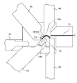
図11に示すように、第2パンチ4bを斜め下方に向けて移動し、その第2パンチ4bの鉤形状の加工面51で素材15をマンドレル3cの一端部上面30a、円弧状湾曲面34に押しつけてV字形状に折り曲げ加工する。素材15は、素材15の一側部16aと素材15の端部側を折り曲げた他側部16bでV字形状の第1加工品16なる。
このように素材15は第2パンチ4bによって加工され曲げられて加工品16となり、図11に示すように第1加工品16となる。
このように素材15は第2パンチ4bによって加工され曲げられて加工品16となり、図11に示すように第1加工品16となる。
図12に示すように、前述の状態のまま第5パンチ4eを上方に移動し、第1パンチ4aを下方の切断位置まで移動し、第1パンチ4aの下向き突部52と第5パンチ4eの上面で素材15を切断する。第1パンチ4aの下向き突部52は素材15を切断する刃となり、第5パンチ4eの上部は刃を受ける刃受部となっている。
素材15を切断後に第5パンチ4eを下方に移動し、図13に示すように第3パンチ4cを移動して第1加工品16の他側部16bをマンドレル3cの一側面31の第1側面31b、第2側面31c、第3側面31dに押しつけ、停止用板バネ10の他側部13と同一形状に折り曲げ加工する。
このように第1加工品16に加工された素材15が切断されて、第1加工品16を第3パンチ4cによって加工して曲げて図13に示すように第2加工品17とする。
素材15を切断後に第5パンチ4eを下方に移動し、図13に示すように第3パンチ4cを移動して第1加工品16の他側部16bをマンドレル3cの一側面31の第1側面31b、第2側面31c、第3側面31dに押しつけ、停止用板バネ10の他側部13と同一形状に折り曲げ加工する。
このように第1加工品16に加工された素材15が切断されて、第1加工品16を第3パンチ4cによって加工して曲げて図13に示すように第2加工品17とする。
そして、図14に示すように第3パンチ4cが第2加工品17を加工完了してマンドレル3cと離れる方向に移動開始した時点で、第1パンチ4aを切断位置からさらに下方に移動して第2加工品17の一側部17aをマンドレル3cの中間部上面30b、他側部上面30cに押しつけて、停止用板バネ10の一側部12と同一形状に折り曲げ加工する。
第3パンチ4cを移動開始して第2加工品17の他側部17bと離間してから若干の時間遅れ後に第1パンチ4aを下方に移動して第2加工品17の一側部17aを加工する。
このように第2加工品17は第1パンチ4aによって加工され曲げられ第3加工品18となる。
第3パンチ4cを移動開始して第2加工品17の他側部17bと離間してから若干の時間遅れ後に第1パンチ4aを下方に移動して第2加工品17の一側部17aを加工する。
このように第2加工品17は第1パンチ4aによって加工され曲げられ第3加工品18となる。
素材15は、マンドレル3cの主体部3c-1の外周面と複数のパンチによって順次、形状を変化させ変形されて加工品となる。マンドレル3cの主体部3c-1は、素材15を成形する第1加工部となっている。
第1パンチ4aが第2加工品17の一側部17aを加工完了後にマンドレル3cと離れる方向に向かって上方へ移動し、マンドレル3cを後退位置bに移動して第3加工品18がマンドレル3cの突起35に接するようになる。マンドレル3cの主体部3c-1で成形された加工品(第3加工品18)が、次にマンドレル3cの突起35の加工面で曲げ加工される。
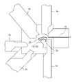
この状態で図15に示すように第4パンチ4dを斜め上方に向けて移動し、第3加工品18の他側部18bを突起35の下面35cに押しつけて折り曲げ加工する。
なお、スプリングバックを考慮して第3加工品18の一側部18aと他側部18bの角度を実際の停止用板バネ10の一側部12と他側部13との角度よりも小さく加工している。
このように第3加工品18は第4パンチ4dによって加工され曲げられ第4加工品19となる。
この状態で図15に示すように第4パンチ4dを斜め上方に向けて移動し、第3加工品18の他側部18bを突起35の下面35cに押しつけて折り曲げ加工する。
なお、スプリングバックを考慮して第3加工品18の一側部18aと他側部18bの角度を実際の停止用板バネ10の一側部12と他側部13との角度よりも小さく加工している。
このように第3加工品18は第4パンチ4dによって加工され曲げられ第4加工品19となる。
マンドレル3cの突起35は、マンドレル3cの主体部3c-1で一次加工された加工品16を2次加工する第2加工部となっている。
図10(a)に示すようにマンドレル3cの主体部3c-1は、マンドレル挿入孔3bを前方に移動してマンドレル3cの端面から長手方向に突出した状態で複数のパンチにより素材15を一次加工し加工品に成形する第1加工部となる。
一次加工の終了後に、図10(b)に示すようにマンドレル3cの主体部3c-1はマンドレル挿入孔3bを後方に移動する。それにともない加工品は主体部3c-1から突起35に移動する。マンドレル3cの突起35は主体部3c-1により一次加工された加工品をパンチにより二次加工する第2加工部となる。
マンドレル3cの移動により加工品の位置を主体部3c-1の外周面及び突起35の外周面に切り換えて、主体部3c-1で加工品を第1形態に曲げ加工し、突起35で加工品を第2形態に曲げ加工する。
図10(a)に示すようにマンドレル3cの主体部3c-1は、マンドレル挿入孔3bを前方に移動してマンドレル3cの端面から長手方向に突出した状態で複数のパンチにより素材15を一次加工し加工品に成形する第1加工部となる。
一次加工の終了後に、図10(b)に示すようにマンドレル3cの主体部3c-1はマンドレル挿入孔3bを後方に移動する。それにともない加工品は主体部3c-1から突起35に移動する。マンドレル3cの突起35は主体部3c-1により一次加工された加工品をパンチにより二次加工する第2加工部となる。
マンドレル3cの移動により加工品の位置を主体部3c-1の外周面及び突起35の外周面に切り換えて、主体部3c-1で加工品を第1形態に曲げ加工し、突起35で加工品を第2形態に曲げ加工する。
各パンチ4a,4b,4c,4d,4eをマンドレル3cから離れる方向に移動することで、第4加工品19は図16に示すように停止用板バネ10となる。
この停止用板バネ10は落下しないように突起35で支持されている。
この停止用板バネ10は落下しないように突起35で支持されている。
この状態で図10(c)に示すようにマンドレル3cを最後退位置cに移動し、突起35による停止用板バネ10の支持が解除されて突起35から停止用板バネ10が排出用空間3d-1に落下する。さらにエア供給部8からマンドレル部3のマンドレル挿入孔3bに供給されたエアがエアノズル46に流入してエアノズル46から排出されて成形完了した停止用板バネ10に吹きつけられ、停止用板バネ10が排出用空間3d-1に吹き飛ばされる。
これと同時に排出部6のエア噴出孔63からエアを噴出して排出部6を負圧として排出用空間3d-1のエアを吸い込むことで、排出用空間3d-1に吹き飛ばされた停止用板バネ10が排出部6に確実に排出され、収容部7に収容される。
これと同時に排出部6のエア噴出孔63からエアを噴出して排出部6を負圧として排出用空間3d-1のエアを吸い込むことで、排出用空間3d-1に吹き飛ばされた停止用板バネ10が排出部6に確実に排出され、収容部7に収容される。
前述の実施の形態では、長尺な素材15を供給して所定の長さに切断したが、予め所定の長さに切断した素材15を供給しても良い。この場合には第5パンチ4eが不要である。停止用板バネの形状によって停止用板バネ成形機のパンチの数や移動するパンチの角度、パンチの形状とマンドレルの形状を変更することができる。
また、マンドレル3cをマンドレル挿入孔3bの長手方向に移動させずにマンドレル3cの位置を固定位置としてパンチ4と素材15をマンドレル3cの長手方向に移動して主体部3c-1の加工面で曲げ加工する状態と、突起35の加工面で曲げ加工する状態に切り換えて素材15を加工し停止用板バネ10を成形するようにしても良い。
また、排出部6の第1筒体60にエア供給部8を設け、エア供給部8から第1筒体60に供給されたエアによって停止用板バネ10を排出することも可能である。
また、マンドレル3cをマンドレル挿入孔3bの長手方向に移動させずにマンドレル3cの位置を固定位置としてパンチ4と素材15をマンドレル3cの長手方向に移動して主体部3c-1の加工面で曲げ加工する状態と、突起35の加工面で曲げ加工する状態に切り換えて素材15を加工し停止用板バネ10を成形するようにしても良い。
また、排出部6の第1筒体60にエア供給部8を設け、エア供給部8から第1筒体60に供給されたエアによって停止用板バネ10を排出することも可能である。
3a…マンドレルホルダー、3b…マンドレル挿入孔、3c…マンドレル、3c-1…主体部(第1加工部)、4…パンチ、5…パンチ移動部、6…排出部、7…収容部、8…エア供給部、10…停止用板バネ、11…円弧状湾曲部、12…一側部、13他側部、15…素材、16…第1加工品、17…第2加工品、18…第3加工品、19…第4加工品、30…上面(一側加工面)、31…一側面(他側加工面)、34…円弧状湾曲面、35…突起(第2加工部)、35a…上面(一方の加工面)、35b…円弧状湾曲面、35c…下面(他方の加工面)、46…エアノズル、63…エア噴出孔。
Claims (8)
- スライドファスナー用スライダーの停止用板バネ(10)を成形する成形機であって、
成形機はマンドレル(3c)と、該マンドレル(3c)の周囲に設けた複数のパンチを備え、
前記パンチをマンドレル(3c)に向けて移動することで素材をマンドレル(3c)の外周面に沿って曲げ加工して停止用板バネ(10)へ成形し、
停止用板バネ(10)は湾曲部(11)と、この湾曲部(11)の一端部と連続した一側部(12)と、湾曲部(11)の他端部と連続した他側部(13)を有し、
前記マンドレル(3c)は素材を停止用板バネ(10)に成形する加工部を設け、前記加工部は停止用板バネ(10)の前記一側部(12)を曲げ加工する一側加工面と、前記他側部(13)を曲げ加工する他側加工面と、を有し、
前記パンチは、前記マンドレル(3c)の加工部の加工面に沿って素材を曲げ加工して停止用板バネ(10)の前記一側部(12)と他側部(13)を曲げ加工する停止用板バネ成形機。 - 成形機は前記マンドレル(3c)とマンドレルホルダー(3a)を有し、前記マンドレルホルダー(3a)のマンドレル挿入孔(3b)を前記マンドレル(3c)が往復移動し、
前記マンドレル(3c)の加工部は、停止用板バネ(10)を成形する第1加工部(3c-1)と第2加工部(35)を有する請求項1記載の停止用板バネ成形機。 - 前記マンドレル(3c)は、前記第1加工部(3c-1)と前記第1加工部(3c-1)から前記マンドレル(3c)の移動方向に突出した第2加工部(35)と、を有し、
前記マンドレル(3c)は第1加工部(3c-1)の加工面がパンチと対向した位置と、第2加工部(35)の加工面がパンチと対向した位置に移動自在とし、
前記マンドレル(3c)の第1加工部(3c-1)の加工面に沿って停止用板バネ(10)を曲げ加工する状態と、マンドレル(3c)の第2加工部(35)の加工面に沿って停止用板バネ(10)を曲げ加工する状態とに前記マンドレル(3c)の位置を切り換える請求項2記載の停止用板バネ成形機。 - 前記マンドレル(3c)は前記マンドレルホルダー(3a)の前記マンドレル挿入孔(3b)を移動し、
前記マンドレル(3c)の前記第1加工部(3c-1)と第2加工部(35)が前記マンドレル挿入孔(3b)から突出した前進位置と、
第2加工部(35)が前記マンドレル挿入孔(3b)から突出し前記第1加工部(3c-1)が前記マンドレル挿入孔(3b)に没した第1の後退位置と、
マンドレル挿入孔(3b)内に前記マンドレル(3c)の前記第1加工部(3c-1)及び第2加工部(35)を没した第2の後退位置とに渡って移動自在とした請求項3記載の停止用板バネ成形機。 - 成形機は前記マンドレル(3c)の一側加工面に向けて長尺な素材(15)を連続して供給する素材供給部を備え、
成形機は長尺な素材(15)を切断するパンチを設けた請求項2又は3記載の停止用板バネ成形機。 - 成形機は、前記マンドレル(3c)と前記パンチで成形した停止用板バネ(10)を排出する排出部(6)を設け、
前記マンドレル(3c)の加工面に沿って気体を吹きつける気体吹きつけ手段と、前記排出部(6)を負圧とする負圧発生手段を設けた請求項2記載の停止用板バネ成形機。 - 成形機は、前記マンドレル挿入孔(3b)と連続した排出部(6)を設け、
前記マンドレル(3c)とマンドレル挿入孔(3b)との間に気体が流れるエアノズル(46)を形成し、
成形機に設けた気体供給部(8)から前記エアノズル(46)に気体を供給し、前記気体供給部(8)と前記エアノズル(46)により気体吹きつけ手段を形成し、
前記排出部(6)に気体を噴出する気体噴出孔(63)を設けて前記負圧発生手段とした請求項6記載の停止用板バネ成形機。 - 成形機に設けられた排出部(6)は第1筒体(60)と第2筒体(62)を備え、前記第1筒体(60)は前記第2筒体(62)と連通する状態と、前記第2筒体(62)と連通しない状態に姿勢変化する請求項6又は7記載の停止用板バネ成形機。
Priority Applications (3)
| Application Number | Priority Date | Filing Date | Title |
|---|---|---|---|
| CN201480004104.8A CN105142455B (zh) | 2014-02-27 | 2014-02-27 | 停止用板弹簧成形机 |
| PCT/JP2014/054922 WO2015128996A1 (ja) | 2014-02-27 | 2014-02-27 | 停止用板バネ成形機 |
| TW104106135A TWI587938B (zh) | 2014-02-27 | 2015-02-26 | 停止用板彈簧成形機 |
Applications Claiming Priority (1)
| Application Number | Priority Date | Filing Date | Title |
|---|---|---|---|
| PCT/JP2014/054922 WO2015128996A1 (ja) | 2014-02-27 | 2014-02-27 | 停止用板バネ成形機 |
Publications (1)
| Publication Number | Publication Date |
|---|---|
| WO2015128996A1 true WO2015128996A1 (ja) | 2015-09-03 |
Family
ID=54008365
Family Applications (1)
| Application Number | Title | Priority Date | Filing Date |
|---|---|---|---|
| PCT/JP2014/054922 Ceased WO2015128996A1 (ja) | 2014-02-27 | 2014-02-27 | 停止用板バネ成形機 |
Country Status (3)
| Country | Link |
|---|---|
| CN (1) | CN105142455B (ja) |
| TW (1) | TWI587938B (ja) |
| WO (1) | WO2015128996A1 (ja) |
Families Citing this family (3)
| Publication number | Priority date | Publication date | Assignee | Title |
|---|---|---|---|---|
| CN108723239B (zh) * | 2017-04-18 | 2020-07-10 | Ykk株式会社 | 成型机、金属材的成型方法、以及停止爪部件的制造方法 |
| CN108723238B (zh) * | 2017-04-18 | 2020-10-02 | Ykk株式会社 | 成型机、金属材的成型方法、以及停止爪部件的制造方法 |
| CN108723179B (zh) * | 2017-04-24 | 2020-09-01 | Ykk株式会社 | 成型机及芯轴的更换方法 |
Citations (3)
| Publication number | Priority date | Publication date | Assignee | Title |
|---|---|---|---|---|
| JPS56152604A (en) * | 1981-03-16 | 1981-11-26 | Yoshida Kogyo Kk | Production of spring with nail of slider with stop apparatus for slide fastener |
| JPH11127918A (ja) * | 1997-10-29 | 1999-05-18 | Ykk Corp | スライドファスナー用スライダーの半自動または自動停止装置 |
| JP2003010916A (ja) * | 2001-06-27 | 2003-01-15 | Toshikazu Okuno | 多方向曲げ加工機械の自動制御装置 |
-
2014
- 2014-02-27 WO PCT/JP2014/054922 patent/WO2015128996A1/ja not_active Ceased
- 2014-02-27 CN CN201480004104.8A patent/CN105142455B/zh active Active
-
2015
- 2015-02-26 TW TW104106135A patent/TWI587938B/zh active
Patent Citations (3)
| Publication number | Priority date | Publication date | Assignee | Title |
|---|---|---|---|---|
| JPS56152604A (en) * | 1981-03-16 | 1981-11-26 | Yoshida Kogyo Kk | Production of spring with nail of slider with stop apparatus for slide fastener |
| JPH11127918A (ja) * | 1997-10-29 | 1999-05-18 | Ykk Corp | スライドファスナー用スライダーの半自動または自動停止装置 |
| JP2003010916A (ja) * | 2001-06-27 | 2003-01-15 | Toshikazu Okuno | 多方向曲げ加工機械の自動制御装置 |
Also Published As
| Publication number | Publication date |
|---|---|
| TWI587938B (zh) | 2017-06-21 |
| CN105142455A (zh) | 2015-12-09 |
| TW201532698A (zh) | 2015-09-01 |
| CN105142455B (zh) | 2017-11-28 |
Similar Documents
| Publication | Publication Date | Title |
|---|---|---|
| CN201012377Y (zh) | 管件扩孔、冲孔、缩孔和/或毛边处理设备 | |
| US8499668B2 (en) | Discharging workpiece parts | |
| US9259776B2 (en) | Manufacturing apparatus for heat exchanger fins | |
| JP6157195B2 (ja) | プレート状のワークピースに成形部を形成するための方法 | |
| CN104841760B (zh) | 一种连续制造冲压产品的方法和采用该方法的冲床 | |
| US9849499B2 (en) | Device and method for transferring workpieces into and out of a tool | |
| CN106513478B (zh) | 机械手辅助阀芯自动折弯设备 | |
| JP2017113767A (ja) | 駒連結ピン加工装置 | |
| TWI587938B (zh) | 停止用板彈簧成形機 | |
| CN201108940Y (zh) | 杆材裁切装置 | |
| JP2020189296A (ja) | プレス機及びプレス成形方法 | |
| CN205587519U (zh) | 管件变薄反拉伸类级进模 | |
| CN202683769U (zh) | 倒装式挤切修边模 | |
| CN205629098U (zh) | 支架折弯圆弧成形类级进模 | |
| CN211135051U (zh) | 一种l型工件切断折弯机 | |
| US4730477A (en) | Workpiece feeding-ejection mechanism | |
| CN201603792U (zh) | Led支架冲压模具 | |
| CN213469306U (zh) | 一种适用于冲压模具的模内移料机构 | |
| JP3566101B2 (ja) | 曲げ金型のワーク排出装置 | |
| CN208555823U (zh) | 一种卡扣复合模具 | |
| CN112317602A (zh) | 全自动阀片高速冲孔机 | |
| CN110193709B (zh) | 一种五金铆压件铆钉送料压合系统 | |
| CN118455378B (zh) | 一种汽车悬架稳定杆成型装置及成型方法 | |
| CN204996904U (zh) | 多工位液压拉伸机 | |
| CN112317632B (zh) | 全自动阀片冲孔机用上下料装置 |
Legal Events
| Date | Code | Title | Description |
|---|---|---|---|
| WWE | Wipo information: entry into national phase |
Ref document number: 201480004104.8 Country of ref document: CN |
|
| 121 | Ep: the epo has been informed by wipo that ep was designated in this application |
Ref document number: 14883958 Country of ref document: EP Kind code of ref document: A1 |
|
| DPE1 | Request for preliminary examination filed after expiration of 19th month from priority date (pct application filed from 20040101) | ||
| NENP | Non-entry into the national phase |
Ref country code: DE |
|
| 122 | Ep: pct application non-entry in european phase |
Ref document number: 14883958 Country of ref document: EP Kind code of ref document: A1 |
|
| NENP | Non-entry into the national phase |
Ref country code: JP |