WO2015125645A1 - 携帯端末装置 - Google Patents
携帯端末装置 Download PDFInfo
- Publication number
- WO2015125645A1 WO2015125645A1 PCT/JP2015/053516 JP2015053516W WO2015125645A1 WO 2015125645 A1 WO2015125645 A1 WO 2015125645A1 JP 2015053516 W JP2015053516 W JP 2015053516W WO 2015125645 A1 WO2015125645 A1 WO 2015125645A1
- Authority
- WO
- WIPO (PCT)
- Prior art keywords
- light
- terminal device
- illuminance sensor
- display
- housing
- Prior art date
- Legal status (The legal status is an assumption and is not a legal conclusion. Google has not performed a legal analysis and makes no representation as to the accuracy of the status listed.)
- Ceased
Links
Images






Classifications
-
- H—ELECTRICITY
- H04—ELECTRIC COMMUNICATION TECHNIQUE
- H04M—TELEPHONIC COMMUNICATION
- H04M1/00—Substation equipment, e.g. for use by subscribers
- H04M1/02—Constructional features of telephone sets
- H04M1/0202—Portable telephone sets, e.g. cordless phones, mobile phones or bar type handsets
- H04M1/026—Details of the structure or mounting of specific components
-
- H—ELECTRICITY
- H04—ELECTRIC COMMUNICATION TECHNIQUE
- H04M—TELEPHONIC COMMUNICATION
- H04M1/00—Substation equipment, e.g. for use by subscribers
- H04M1/02—Constructional features of telephone sets
- H04M1/0202—Portable telephone sets, e.g. cordless phones, mobile phones or bar type handsets
- H04M1/026—Details of the structure or mounting of specific components
- H04M1/0266—Details of the structure or mounting of specific components for a display module assembly
-
- H—ELECTRICITY
- H04—ELECTRIC COMMUNICATION TECHNIQUE
- H04M—TELEPHONIC COMMUNICATION
- H04M1/00—Substation equipment, e.g. for use by subscribers
- H04M1/72—Mobile telephones; Cordless telephones, i.e. devices for establishing wireless links to base stations without route selection
- H04M1/724—User interfaces specially adapted for cordless or mobile telephones
- H04M1/72448—User interfaces specially adapted for cordless or mobile telephones with means for adapting the functionality of the device according to specific conditions
- H04M1/72454—User interfaces specially adapted for cordless or mobile telephones with means for adapting the functionality of the device according to specific conditions according to context-related or environment-related conditions
Definitions
- the present invention relates to a mobile terminal device, and more particularly to a mobile terminal device capable of adjusting the brightness of a display unit in accordance with external brightness.
- one of the functions of a mobile phone is to automatically adjust the display brightness according to the brightness of the surrounding environment in order to reduce power consumption and improve visibility.
- Patent Document 1 discloses a mobile terminal device.
- the mobile terminal device adjusts the brightness of the display device according to the light detection current of the illuminance sensor, and the first external light incident from the housing surface of the mobile terminal device facing the display device is transmitted from the housing surface.
- a first light guiding means for guiding light to the illuminance sensor; and a second light guiding means for guiding second external light incident from the rear surface of the housing opposite to the display device to the illuminance sensor. Have.
- an illuminance sensor is provided below the frame, which is a non-display area around the display device, in order to adjust the brightness of the display device according to the external brightness. Therefore, it is necessary to secure a region for providing the illuminance sensor in the frame portion, and so-called narrow frame cannot be realized.
- the present invention has been made to solve the above-described problems, and provides a portable terminal device that can detect external brightness by an illuminance sensor and further facilitates narrowing of the frame. With the goal.
- a portable terminal device includes a display, a housing having an edge that forms an opening that exposes the display, and housing the display; an illuminance sensor provided on the opposite side of the display surface of the display; A light guide that includes a light inlet provided in the edge and guides external light incident from the light inlet into the housing to the illuminance sensor.
- the external brightness can be detected by the illuminance sensor and the narrowing of the frame is further promoted.
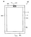
- FIG. 3 is a plan view showing a mobile terminal device according to the first embodiment.
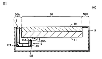
- FIG. 2 is a schematic cross-sectional view of the mobile terminal device shown in FIG. 1 taken along line II-II shown in FIG. It is an enlarged view of the light inlet opening peripheral part provided in the surface of the housing
- 6 is a plan view showing a portable terminal device according to a second embodiment.
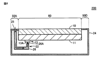
- FIG. FIG. 6 is a schematic cross-sectional view of the mobile terminal device shown in FIG. 5 taken along line VI-VI in FIG.
- FIG. 9 is a plan view showing a mobile terminal device according to a third embodiment.
- FIG. 8 is a schematic cross-sectional view of the mobile terminal device shown in FIG. 7 taken along line VIII-VIII shown in FIG.
- FIG. 10 is a plan view showing a mobile terminal device according to a fourth embodiment.
- FIG. 10 is a side view of the mobile terminal device as viewed from the arrow X direction shown in FIG. 9 of the mobile terminal device shown in FIG. 9.
- FIG. 10 is a schematic cross-sectional view of the mobile terminal device shown in FIG. 9 along the line XI-XI shown in FIG.
- a mobile terminal device 100 according to the first embodiment will be described with reference to FIGS.
- the mobile terminal device 100 is a smartphone, a tablet terminal device, a PDA (Personal Data Assistance), or the like.
- FIG. 1 is a plan view showing portable terminal device 100 according to the first embodiment.
- FIG. 2 is a schematic cross-sectional view taken along the line II-II shown in FIG. 1 of the mobile terminal device 100 shown in FIG.
- FIG. 3 is an enlarged view of the periphery of the light inlet 15 provided on the surface of the housing 14 of the mobile terminal device 100.
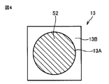
- FIG. 4 is a diagram showing a light receiving surface 13 ⁇ / b> A of the illuminance sensor 13 provided inside the housing 14 of the mobile terminal device 100.
- the mobile terminal device 100 has a flat, substantially rectangular parallelepiped outer shape as a whole.
- the mobile terminal device 100 includes a display 10, a circuit board 11, a light guide member 12, an illuminance sensor 13, and a housing 14.
- the mobile terminal device 100 may include an operation button (not shown) for receiving an instruction from the user.
- the display 10 is a liquid crystal display or an organic EL display.
- the housing 14 accommodates the display 10, the circuit board 11, the light guide member 12 as a light guide unit, and the illuminance sensor 13.
- the housing 14 also has an edge 50 (an upper edge 50A, a left edge 50B, a right edge 50C, and a lower edge 50D) that forms an opening 60 for exposing the display 10.
- the circuit board 11 is provided on the surface opposite to the display surface side of the display 10 inside the housing 14.
- the circuit board 11 includes a control unit (not shown) that supplies power to the illuminance sensor 13 and controls the luminance of the display 10 based on output values (electromotive force, photodetection current, etc.) output from the illuminance sensor 13. Have.
- the control unit adjusts the luminance of the display 10 depending on whether or not the output value exceeds a preset reference value. That is, the control unit increases the brightness of the display 10 in a bright place to make the display easy to see, and reduces the brightness in a dark place to prevent glare.
- the light guide member 12 includes a light inlet 15 provided at the upper edge portion 50A facing the display 10.
- the light guide member 12 guides external light incident on the inside of the housing 14 from the light intake port 15 to the illuminance sensor 13.
- the light guide member 12 is provided in the light guide path 16 for guiding external light incident on the inside of the housing 14 from the light inlet 15 to the illuminance sensor 13, and the light guide path 16.
- the light guide 16 is constituted by a hollow waveguide.
- the reflection member 17A reflects the external light incident from the light inlet 15 toward the reflection member 17B. Then, the reflection member 17B reflects the external light reflected by the reflection member 17A toward the light receiving surface 13A of the illuminance sensor 13 through the emission surface 16A. In the light guide path 16, two or more reflecting members may be provided.
- the illuminance sensor 13 is provided on the surface of the circuit board 11 opposite to the side where the display 10 is located.
- the illuminance sensor 13 includes a light receiving surface 13A having a light receiving portion (light receiving element) that detects light, and a mounting portion 13B that supports the light receiving portion and is attached to the circuit board 11.
- the illuminance sensor 13 receives external light guided by the light guide member 12 by the light receiving surface 13 ⁇ / b> A and detects the illuminance outside the housing 14. Specifically, the illuminance sensor 13 outputs a signal corresponding to the amount of light received by the light receiving surface 13A to the control unit.
- the illuminance sensor 13 is a photodiode, a phototransistor, or the like.
- the illuminance sensor 13 is configured so that the exit surface 16A of the light guide 16 from which external light is emitted and the light receiving surface 13A of the illuminance sensor 13 face each other. Placed in.
- illuminance sensor 13 is provided inside casing 14, external light that has entered from light intake 15 is guided to illuminance sensor 13 by light guide member 12. The Therefore, the illuminance sensor 13 can reliably detect the external brightness.
- the illuminance sensor 13 is provided inside the housing 14, an area that needs to be secured at the edge 50 in order to detect external brightness is a light intake port that takes outside light into the housing 14. 15 may be provided.
- the opening area S1 of the light inlet 15 provided in the upper edge portion 50A of the housing 14 is set to the area of the light receiving surface 13A of the illuminance sensor 13. It is made smaller than S2.
- the opening area S ⁇ b> 1 of the light inlet 15 is set to be at least smaller than the area of the mounting portion 13 ⁇ / b> B of the illuminance sensor 13.
- FIG. 5 is a plan view showing portable terminal device 200 according to the second embodiment.
- FIG. 6 is a schematic cross-sectional view taken along line VI-VI shown in FIG. 5 of the mobile terminal device 200 shown in FIG.
- differences between the mobile terminal device 200 and the mobile terminal device 100 will be described.
- the mobile terminal device 200 includes a display 10, a circuit board 11, a light guide member 22 as a light guide unit, an illuminance sensor 13, and a housing 24.
- the mobile terminal device 200 differs from the mobile terminal device 100 in the configuration of the housing and the light guide member.
- the housing 24 accommodates the display 10, the circuit board 11, the light guide member 22, and the illuminance sensor 13.
- the housing 14 also has an edge portion 50 that forms an opening 60 for exposing the display 10.
- the light guide member 22 includes a light inlet 25 provided in the upper edge portion 50A.
- the light guide member 22 guides external light incident on the inside of the housing 24 from the light intake port 25 to the illuminance sensor 13.
- the light guide member 22 includes an optical waveguide 26 serving as a light guide for guiding external light incident on the inside of the housing 24 from the light intake port 25 to the illuminance sensor 13.
- the optical waveguide 26 is an optical fiber.
- the illuminance sensor 13 is disposed so that the light exit surface 26A of the optical waveguide 26 from which external light is emitted and the light receiving surface 13A of the illuminance sensor 13 face each other. Further, the opening area of the light inlet 25 is smaller than the area of the light receiving surface 13A of the illuminance sensor 13 (or the area of the mounting portion).
- the portable terminal device 200 Even in the portable terminal device 200 according to the second embodiment, it is possible to reduce the width of the edge portion 50 and promote the narrowing of the frame rather than the configuration in which the illuminance sensor 13 is provided at the edge portion. Furthermore, since portable terminal device 200 uses optical waveguide 26 as a light guide path, external light can be guided to illuminance sensor 13 more efficiently than portable terminal device 100 according to the first embodiment. . Therefore, the mobile terminal device 200 can detect the external brightness with higher accuracy.
- FIG. 7 is a plan view showing portable terminal device 300 according to the third embodiment.
- FIG. 8 is a schematic cross-sectional view of the mobile terminal device 300 shown in FIG. 7 along the line VIII-VIII shown in FIG.
- differences between the mobile terminal device 300 and the mobile terminal device 200 see FIGS. 5 and 6) will be described.
- the portable terminal device 300 includes a display 10, a circuit board 11, a light guide member 32 as a light guide unit, an illuminance sensor 13, and a housing 34.
- the mobile terminal device 300 corresponds to a configuration in which a plurality of light inlets are provided in the mobile terminal device 200.
- the housing 34 accommodates the display 10, the circuit board 11, the light guide member 32, and the illuminance sensor 13. Further, the housing 34 has an edge portion 50 that forms an opening 60 for exposing the display 10.
- the light guide member 32 includes a light inlet 35A provided at the upper edge portion 50A, a light inlet 35B provided at the left edge portion 50B, and a light inlet 35C provided at the right edge portion 50C.
- the light guide member 32 includes an optical waveguide 36 as a light guide for guiding external light incident on the inside of the housing 34 from each of the light intake ports 35A to 35C to the illuminance sensor 13.
- the illuminance sensor 13 is arranged so that the emission surface 36A of the optical waveguide 36 from which external light is emitted and the light receiving surface 13A of the illuminance sensor 13 face each other. Further, the opening areas of the light inlets 35A, 35B, and 35C are smaller than the area of the light receiving surface 13A of the illuminance sensor 13 (or the area of the mounting portion).
- the mobile terminal device 300 it is possible to reduce the width of the edge portion 50 and promote narrowing of the frame as compared with the configuration in which the illuminance sensor 13 is provided at the edge portion.
- the mobile terminal device 300 includes a plurality of light inlets 35A to 35C on the surface of the housing 34. Therefore, when the opening area of each of the light inlets 35A to 35C is the same as the opening area of the light inlet 25 according to the second embodiment, the mobile terminal device 300 is more than the mobile terminal device 200. External light can be guided to the illuminance sensor 13. In this case, the mobile terminal device 300 can detect the external brightness with higher accuracy than the mobile terminal device 200.
- the mobile terminal device 300 uses the opening area of each of the light inlets 35A to 35C as light. By making it smaller than the opening area of the intake port 25, the width of each edge (upper edge 50A, left edge 50B, right edge 50C) may be reduced.
- FIG. 9 is a plan view showing portable terminal device 400 according to the fourth embodiment.
- FIG. 10 is a side view of the mobile terminal device 400 when viewed from the arrow X direction shown in FIG. 9 of the mobile terminal device 400 shown in FIG.
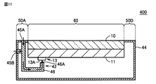
- FIG. 11 is a schematic cross-sectional view taken along line XI-XI shown in FIG. 9 of the mobile terminal device 400 shown in FIG.
- differences between the mobile terminal device 400 and the mobile terminal device 200 will be described.
- the mobile terminal device 400 includes a display 10, a circuit board 11, a light guide member 42 as a light guide unit, an illuminance sensor 13, and a housing 44.
- the housing 44 accommodates the display 10, the circuit board 11, the light guide member 42, and the illuminance sensor 13. Further, the housing 44 has an edge portion 50 that forms an opening 60 for exposing the display 10.
- the light guide member 42 includes light inlets 45A and 45B.
- the light inlet 45A is provided in the upper edge portion 50A that the display 10 faces.
- the light inlet 45B is provided on the side surface of the housing 44 (the surface of the housing 44 that the display 10 does not face).
- the light guide member 42 guides external light incident on the inside of the housing 44 from the light intake 45A and the light intake 45B to the illuminance sensor 13.
- the light guide member 42 includes an optical waveguide 46 for guiding external light incident on the inside of the housing 44 from the light inlet 45 ⁇ / b> A and the light inlet 45 ⁇ / b> B to the illuminance sensor 13. .
- the illuminance sensor 13 is disposed so that the emission surface 46A of the optical waveguide 46 from which external light is emitted and the light receiving surface 13A of the illuminance sensor 13 face each other.
- the opening areas of the light intake ports 45A and 45B are smaller than the area of the light receiving surface 13A of the illuminance sensor 13 (or the area of the mounting portion).
- the mobile terminal device 400 according to the fourth embodiment it is possible to reduce the width of the edge portion and promote the narrowing of the frame rather than the configuration in which the illuminance sensor 13 is provided at the edge portion. Furthermore, since the portable terminal device 400 according to the fourth embodiment is provided with the light intake port 45B on the side surface of the housing 44, the portable terminal device 400 is stable even if the direction in which the user grips the portable terminal device 400 is slightly changed. Thus, it becomes possible to capture external light.
- the configuration using the optical waveguide as the light guide has been described, but the configuration using the light guide 16 and the reflecting members 17A and 17B in the first embodiment may be used.
- a configuration may be employed in which the third and fourth embodiments are combined to provide a plurality of light inlets at the edge and also provide a light inlet at the side surface.
- 10 display 11 circuit board, 12, 22, 32, 42 light guide member, 13 illuminance sensor, 13A light receiving surface, 13B mounting portion, 14, 24, 34, 44 housing, 15, 25, 35A, 35B, 35C, 45A, 45B light inlet, 16 light guide, 16A, 26A, 36A, 46A exit surface, 17A, 17B reflecting member, 26, 36, 46 optical waveguide, 50 edge, 50A upper edge, 50B left edge , 50C right edge, 50D lower edge, 60 openings, 100, 200, 300, 400 mobile terminal device.
Landscapes
- Engineering & Computer Science (AREA)
- Signal Processing (AREA)
- Telephone Set Structure (AREA)
Abstract
照度センサにより外部の明るさを検出可能であるとともに狭額縁化がより促進された携帯端末装置を提供する。ある実施の形態に従う携帯端末装置(100)は、ディスプレイ(10)と、ディスプレイ(10)を露出させる開口部(60)を形成する縁部(50A、D)を有しディスプレイ(10)を収容する筐体(14)と、ディスプレイ(10)の表示面とは反対側に設けられる照度センサ(13)と、縁部(50A)に設けられる光取込口(15)を含み光取込口(15)から筐体(14)の内部に入射する外光を照度センサ(13)に導光する導光部(16)とを備える。
Description
本発明は、携帯端末装置に関し、特に、外部の明るさに応じて表示部の輝度を調整可能な携帯端末装置に関する。
従来、携帯電話が有する機能の一つとして、消費電力の削減および視認性の向上などのために、周囲環境の明るさに応じてディスプレイの明るさを自動的に調整可能とするものがある。
たとえば、特開2010-122414号公報(特許文献1)には、携帯端末装置が開示されている。携帯端末装置は、照度センサの光検出電流に応じて表示装置の輝度を調整し、表示装置が面している携帯端末装置の筐体表面から入射する第一の外光を、筐体表面から照度センサへ導光する第一の導光手段と、表示装置と反対側の筐体裏面から入射する第二の外光を、筐体裏面から照度センサへ導光する第二の導光手段を有する。
しかしながら、特許文献1の技術によると、外部の明るさに応じて表示装置の輝度を調整するために、照度センサが表示装置の周囲の非表示領域である額縁の下方に設けられている。そのため、照度センサを設けるための領域を額縁部分に確保する必要があり、その分いわゆる狭額縁化を実現することができない。
本発明は、上記のような問題点を解決するためになされたものであって、照度センサにより外部の明るさを検出可能であるとともに狭額縁化がより促進された携帯端末装置を提供することを目的とする。
ある実施の形態に従う携帯端末装置は、ディスプレイと、ディスプレイを露出させる開口部を形成する縁部を有しディスプレイを収容する筐体と、ディスプレイの表示面とは反対側に設けられる照度センサと、縁部に設けられる光取込口を含み光取込口から筐体の内部に入射する外光を照度センサに導光する導光部とを備える。
本発明によれば、照度センサにより外部の明るさを検出可能であるとともに狭額縁化がより促進される。
本発明に基づいた各実施の形態について、以下、図面を参照しながら説明する。各実施の形態の説明において、個数および量などに言及する場合、特に記載がある場合を除き、本発明の範囲は必ずしもその個数およびその量などに限定されない。各実施の形態の説明において、同一の部品および相当部品に対しては、同一の参照番号を付し、重複する説明は繰り返さない場合がある。
[実施の形態1]
図1~図4を参照して、実施の形態1に従う携帯端末装置100について説明する。たとえば、携帯端末装置100は、スマートフォン、タブレット端末装置、PDA(Personal Data Assistance)などである。
図1~図4を参照して、実施の形態1に従う携帯端末装置100について説明する。たとえば、携帯端末装置100は、スマートフォン、タブレット端末装置、PDA(Personal Data Assistance)などである。
図1は、実施の形態1に従う携帯端末装置100を示す平面図である。図2は、図1に示す携帯端末装置100の図1中に示すII-II線に沿った模式断面図である。図3は、携帯端末装置100の筐体14の表面に設けられる光取込口15周辺部の拡大図である。図4は、携帯端末装置100の筐体14の内部に設けられる照度センサ13の受光面13Aを示す図である。
図1および図2に示すように、携帯端末装置100は、全体として扁平な略直方体形状の外形を有する。携帯端末装置100は、ディスプレイ10と、回路基板11と、導光部材12と、照度センサ13と、筐体14とを備える。なお、携帯端末装置100は、ユーザからの指示を受け付けるための操作ボタン(図示しない)を備えていてもよい。たとえば、ディスプレイ10は、液晶ディスプレイあるいは有機ELディスプレイである。
筐体14は、ディスプレイ10と、回路基板11と、導光部としての導光部材12と、照度センサ13とを収容する。また、筐体14は、ディスプレイ10を露出するための開口部60を形成する縁部50(上縁部50A、左縁部50B、右縁部50C、下縁部50D)を有する。
回路基板11は、筐体14の内部において、ディスプレイ10の表示面側とは反対側の面に設けられる。回路基板11は、照度センサ13に電力を供給したり、照度センサ13が出力する出力値(起電力、光検出電流など)に基づきディスプレイ10の輝度を制御したりする制御部(図示しない)を有する。制御部は、その出力値が予め設定した基準値を上回るか否かによって、ディスプレイ10の輝度を調整する。すなわち、制御部は、明るい場所ではディスプレイ10の輝度を上げて表示を見やすくし、暗い場所ではその輝度を下げて眩しさを防止する。
導光部材12は、ディスプレイ10が面している上縁部50Aに設けられる光取込口15を含む。導光部材12は、光取込口15から筐体14の内部に入射する外光を照度センサ13に導光する。具体的には、導光部材12は、光取込口15から筐体14の内部に入射する外光を照度センサ13に導光するための導光路16と、その導光路16内に設けられた2つの反射部材17A,17Bとを有している。たとえば、導光路16は、中空の導波管で構成されている。
反射部材17Aは、光取込口15から入射した外光を反射部材17Bに向けて反射する。そして、反射部材17Bは、反射部材17Aにより反射された外光を出射面16Aを介して照度センサ13の受光面13Aに向けて反射させる。なお、導光路16内には、2つ以上の反射部材が設けられていてもよい。
照度センサ13は、回路基板11における、ディスプレイ10が位置する側とは反対側の面に設けられる。照度センサ13は、光を検出する受光部(受光素子)を有する受光面13Aと、受光部を支持し回路基板11に取り付けられる実装部13Bとを有する。照度センサ13は、導光部材12により導光される外光を受光面13Aで受光して、筐体14の外部の照度を検出する。具体的には、照度センサ13は、受光面13Aで受光した受光量に応じた信号を制御部に出力する。
たとえば、照度センサ13には、フォトダイオード、フォトトランジスタなどが用いられる。なお、外部の照度(明るさ)を精度良く検出できるようにするため、照度センサ13は、外光が出射される導光路16の出射面16Aと照度センサ13の受光面13Aとが対面するように配置される。
実施の形態1に従う携帯端末装置100では、照度センサ13が筐体14内部に設けられているものの、光取込口15から入射した外光は、導光部材12により照度センサ13まで導光される。そのため、照度センサ13は、外部の明るさを確実に検出することができる。
また、照度センサ13を筐体14内部に設けたことにより、外部の明るさを検出するために縁部50において確保する必要のある領域は、外光を筐体14内部に取り込む光取込口15を設けるための領域でよい。
そこで、携帯端末装置100では、図3および図4に示すように、筐体14の上縁部50Aに設けられた光取込口15の開口面積S1を、照度センサ13の受光面13Aの面積S2よりも小さくする。あるいは、光取込口15の開口面積S1は、少なくとも照度センサ13の実装部13Bの面積よりも小さくする。これにより、携帯端末装置100では、照度センサ13を縁部に設ける構成よりも、縁部50の幅を縮小して狭額縁化を促進することができる。
[実施の形態2]
図5および図6を参照して、実施の形態2に従う携帯端末装置200について説明する。図5は、実施の形態2に従う携帯端末装置200を示す平面図である。図6は、図5に示す携帯端末装置200の図5中に示すVI-VI線に沿った模式断面図である。ここでは、携帯端末装置200と携帯端末装置100(図1および図2参照)との相違点について説明する。
図5および図6を参照して、実施の形態2に従う携帯端末装置200について説明する。図5は、実施の形態2に従う携帯端末装置200を示す平面図である。図6は、図5に示す携帯端末装置200の図5中に示すVI-VI線に沿った模式断面図である。ここでは、携帯端末装置200と携帯端末装置100(図1および図2参照)との相違点について説明する。
図5および図6を参照して、携帯端末装置200は、ディスプレイ10と、回路基板11と、導光部としての導光部材22と、照度センサ13と、筐体24とを備える。携帯端末装置200は、携帯端末装置100と比較して、筐体および導光部材の構成が異なる。
筐体24は、ディスプレイ10と、回路基板11と、導光部材22と、照度センサ13とを収容する。また、筐体14は、ディスプレイ10を露出するための開口部60を形成する縁部50を有する。
導光部材22は、上縁部50Aに設けられる光取込口25を含む。導光部材22は、光取込口25から筐体24の内部に入射する外光を照度センサ13に導光する。導光部材22は、光取込口25から筐体24の内部に入射する外光を照度センサ13に導光するための導光路としての光導波体26を有する。たとえば、光導波体26は、光ファイバである。
なお、照度センサ13は、外光が出射される光導波体26の出射面26Aと照度センサ13の受光面13Aとが対面するように配置される。また、光取込口25の開口面積は、照度センサ13の受光面13Aの面積(または実装部分の面積)よりも小さい。
実施の形態2に従う携帯端末装置200でも、照度センサ13を縁部に設ける構成よりも、縁部50の幅を縮小して狭額縁化を促進することができる。さらに、携帯端末装置200では、導光路として光導波体26を用いているため、実施の形態1に従う携帯端末装置100と比較して、外光を効率よく照度センサ13に導光することができる。そのため、携帯端末装置200は、より精度良く外部の明るさを検出することができる。
[実施の形態3]
図7および図8を参照して、実施の形態3に従う携帯端末装置300について説明する。図7は、実施の形態3に従う携帯端末装置300を示す平面図である。図8は、図7に示す携帯端末装置300の図7中に示すVIII-VIII線に沿った模式断面図である。ここでは、携帯端末装置300と携帯端末装置200(図5および図6参照)との相違点について説明する。
図7および図8を参照して、実施の形態3に従う携帯端末装置300について説明する。図7は、実施の形態3に従う携帯端末装置300を示す平面図である。図8は、図7に示す携帯端末装置300の図7中に示すVIII-VIII線に沿った模式断面図である。ここでは、携帯端末装置300と携帯端末装置200(図5および図6参照)との相違点について説明する。
図7および図8を参照して、携帯端末装置300は、ディスプレイ10と、回路基板11と、導光部としての導光部材32と、照度センサ13と、筐体34とを備える。携帯端末装置300は、携帯端末装置200において光取込口を複数設けた構成に相当する。
筐体34は、ディスプレイ10と、回路基板11と、導光部材32と、照度センサ13とを収容する。また、筐体34は、ディスプレイ10を露出するための開口部60を形成する縁部50を有する。
導光部材32は、上縁部50Aに設けられる光取込口35Aと、左縁部50Bに設けられる光取込口35Bと、右縁部50Cに設けられる光取込口35Cとを含む。導光部材32は、光取込口35A~35Cの各々から筐体34の内部に入射する外光を照度センサ13に導光するための導光路としての光導波体36を有する。
なお、照度センサ13は、外光が出射される光導波体36の出射面36Aと照度センサ13の受光面13Aとが対面するように配置される。また、光取込口35A,35B,35Cの開口面積は、照度センサ13の受光面13Aの面積(または実装部分の面積)よりも小さい。
実施の形態3に従う携帯端末装置300でも、照度センサ13を縁部に設ける構成よりも、縁部50の幅を縮小して狭額縁化を促進することができる。
さらに、携帯端末装置300は、その筐体34表面に複数の光取込口35A~35Cを備えている。そのため、各々の光取込口35A~35Cの開口面積と、実施の形態2に従う光取込口25の開口面積とが同じ場合には、携帯端末装置300は、携帯端末装置200よりも多くの外光を照度センサ13まで導光させることが可能となる。この場合、携帯端末装置300は、携帯端末装置200よりも精度良く外部の明るさを検出することができる。
なお、照度センサ13まで導光させる外光の量(受光量)が携帯端末装置200と同等でよい場合には、携帯端末装置300は、各々の光取込口35A~35Cの開口面積を光取込口25の開口面積よりも小さくすることで、各々の縁部(上縁部50A、左縁部50B、右縁部50C)の幅を縮小してもよい。
[実施の形態4]
図9~図11を参照して、実施の形態4に従う携帯端末装置400について説明する。図9は、実施の形態4に従う携帯端末装置400を示す平面図である。図10は、図9に示す携帯端末装置400の図9中に示す矢印X方向から視認したときの携帯端末装置400の側面図である。図11は、図9に示す携帯端末装置400の図9中に示すXI-XI線に沿った模式断面図である。ここでは、携帯端末装置400と携帯端末装置200(図5および図6参照)との相違点について説明する。
図9~図11を参照して、実施の形態4に従う携帯端末装置400について説明する。図9は、実施の形態4に従う携帯端末装置400を示す平面図である。図10は、図9に示す携帯端末装置400の図9中に示す矢印X方向から視認したときの携帯端末装置400の側面図である。図11は、図9に示す携帯端末装置400の図9中に示すXI-XI線に沿った模式断面図である。ここでは、携帯端末装置400と携帯端末装置200(図5および図6参照)との相違点について説明する。
図9~図11を参照して、携帯端末装置400は、ディスプレイ10と、回路基板11と、導光部としての導光部材42と、照度センサ13と、筐体44とを備える。
筐体44は、ディスプレイ10と、回路基板11と、導光部材42と、照度センサ13とを収容する。また、筐体44は、ディスプレイ10を露出するための開口部60を形成する縁部50を有する。
導光部材42は、光取込口45A,45Bを含む。光取込口45Aは、ディスプレイ10が面している上縁部50Aに設けられる。光取込口45Bは、筐体44の側面(ディスプレイ10が面していない筐体44面)に設けられる。
導光部材42は、光取込口45Aおよび光取込口45Bから筐体44の内部に入射する外光を照度センサ13に導光する。具体的には、導光部材42は、光取込口45Aおよび光取込口45Bから筐体44の内部に入射する外光を、照度センサ13に導光するための光導波体46を有する。
なお、照度センサ13は、外光が出射される光導波体46の出射面46Aと照度センサ13の受光面13Aとが対面するように配置される。また、光取込口45A,45Bの開口面積は、照度センサ13の受光面13Aの面積(または実装部分の面積)よりも小さい。
実施の形態4に従う携帯端末装置400でも、照度センサ13を縁部に設ける構成よりも、縁部の幅を縮小して狭額縁化を促進することができる。さらに、実施の形態4に従う携帯端末装置400は、筐体44の側面にも光取込口45Bが設けられているため、ユーザが携帯端末装置400を把持する向きが多少変化したとしても、安定的に外光を取り込むことが可能となる。
[その他の実施の形態]
なお、上述した実施の形態において、他の実施の形態で説明した構成を適宜採用して実施する構成であってもよい。
なお、上述した実施の形態において、他の実施の形態で説明した構成を適宜採用して実施する構成であってもよい。
具体的には、実施の形態3および4では、導光路として光導波体を用いる構成で説明したが、実施の形態1における導光路16および反射部材17A,17Bを用いる構成であってもよい。
また、実施の形態3および4を組み合わせて、縁部に複数の光取込口を設けるとともに、側面にも光取込口を設ける構成であってもよい。
今回開示された実施の形態はすべての点で例示であって制限的なものではないと考えられるべきである。本発明の範囲は、上記した説明ではなく、請求の範囲によって示され、請求の範囲と均等の意味および範囲内でのすべての変更が含まれることが意図される。
10 ディスプレイ、11 回路基板、12,22,32,42 導光部材、13 照度センサ、13A 受光面、13B 実装部、14,24,34,44 筐体、15,25,35A,35B,35C,45A,45B 光取込口、16 導光路、16A,26A,36A,46A 出射面、17A,17B 反射部材、26,36,46 光導波体、50 縁部、50A 上縁部、50B 左縁部、50C 右縁部、50D 下縁部、60 開口部、100,200,300,400 携帯端末装置。
Claims (5)
- ディスプレイと、
前記ディスプレイを露出させる開口部を形成する縁部を有し、前記ディスプレイを収容する筐体と、
前記ディスプレイの表示面とは反対側に設けられる照度センサと、
前記縁部に設けられる光取込口を含み、前記光取込口から前記筐体の内部に入射する外光を前記照度センサに導光する導光部とを備える、携帯端末装置。 - 前記導光部は、
前記光取込口から前記筐体の内部に入射する外光を前記照度センサに導光する導光路と、
前記導光路内に設けられ、前記光取込口から入射した外光を前記照度センサに向けて反射させる反射部材とを有する、請求項1に記載の携帯端末装置。 - 前記導光部は、前記光取込口から入射した外光を前記照度センサに導光する光導波体を有する、請求項1に記載の携帯端末装置。
- 前記縁部には前記光取込口が複数設けられている、請求項1から3のいずれか1項に記載の携帯端末装置。
- 前記導光部は、前記筐体の側面に側面光取込口をさらに含む、請求項1から4のいずれか1項に記載の携帯端末装置。
Applications Claiming Priority (2)
| Application Number | Priority Date | Filing Date | Title |
|---|---|---|---|
| JP2014-028461 | 2014-02-18 | ||
| JP2014028461 | 2014-02-18 |
Publications (1)
| Publication Number | Publication Date |
|---|---|
| WO2015125645A1 true WO2015125645A1 (ja) | 2015-08-27 |
Family
ID=53878151
Family Applications (1)
| Application Number | Title | Priority Date | Filing Date |
|---|---|---|---|
| PCT/JP2015/053516 Ceased WO2015125645A1 (ja) | 2014-02-18 | 2015-02-09 | 携帯端末装置 |
Country Status (1)
| Country | Link |
|---|---|
| WO (1) | WO2015125645A1 (ja) |
Cited By (3)
| Publication number | Priority date | Publication date | Assignee | Title |
|---|---|---|---|---|
| WO2020065946A1 (ja) * | 2018-09-28 | 2020-04-02 | 三菱電機株式会社 | ディスプレイ用導光体及びディスプレイ装置 |
| WO2020179784A1 (ja) * | 2019-03-04 | 2020-09-10 | 日本精機株式会社 | 表示装置 |
| US11587515B2 (en) | 2017-11-22 | 2023-02-21 | Vivo Mobile Communication Co., Ltd. | Terminal device |
Citations (8)
| Publication number | Priority date | Publication date | Assignee | Title |
|---|---|---|---|---|
| JPH1020277A (ja) * | 1996-07-05 | 1998-01-23 | Matsushita Electric Ind Co Ltd | 液晶表示装置 |
| WO2004090487A1 (ja) * | 2003-03-26 | 2004-10-21 | Semiconductor Energy Laboratory Co., Ltd. | 多方向からの光を検出する光センサ、携帯通信機器及び表示方法 |
| JP2009065245A (ja) * | 2007-09-04 | 2009-03-26 | Panasonic Corp | 携帯端末装置 |
| JP2009069314A (ja) * | 2007-09-11 | 2009-04-02 | Panasonic Electric Works Tatsuno Co Ltd | 表示装置 |
| JP2009229908A (ja) * | 2008-03-24 | 2009-10-08 | Casio Comput Co Ltd | 表示装置 |
| WO2011067858A1 (ja) * | 2009-12-04 | 2011-06-09 | 富士通株式会社 | 表示装置および電子機器 |
| JP2012247967A (ja) * | 2011-05-27 | 2012-12-13 | Nec Casio Mobile Communications Ltd | 入力装置、入力方法及びプログラム |
| JP2013125361A (ja) * | 2011-12-13 | 2013-06-24 | Fujitsu Mobile Communications Ltd | 携帯端末、および近接検出制御方法 |
-
2015
- 2015-02-09 WO PCT/JP2015/053516 patent/WO2015125645A1/ja not_active Ceased
Patent Citations (8)
| Publication number | Priority date | Publication date | Assignee | Title |
|---|---|---|---|---|
| JPH1020277A (ja) * | 1996-07-05 | 1998-01-23 | Matsushita Electric Ind Co Ltd | 液晶表示装置 |
| WO2004090487A1 (ja) * | 2003-03-26 | 2004-10-21 | Semiconductor Energy Laboratory Co., Ltd. | 多方向からの光を検出する光センサ、携帯通信機器及び表示方法 |
| JP2009065245A (ja) * | 2007-09-04 | 2009-03-26 | Panasonic Corp | 携帯端末装置 |
| JP2009069314A (ja) * | 2007-09-11 | 2009-04-02 | Panasonic Electric Works Tatsuno Co Ltd | 表示装置 |
| JP2009229908A (ja) * | 2008-03-24 | 2009-10-08 | Casio Comput Co Ltd | 表示装置 |
| WO2011067858A1 (ja) * | 2009-12-04 | 2011-06-09 | 富士通株式会社 | 表示装置および電子機器 |
| JP2012247967A (ja) * | 2011-05-27 | 2012-12-13 | Nec Casio Mobile Communications Ltd | 入力装置、入力方法及びプログラム |
| JP2013125361A (ja) * | 2011-12-13 | 2013-06-24 | Fujitsu Mobile Communications Ltd | 携帯端末、および近接検出制御方法 |
Cited By (5)
| Publication number | Priority date | Publication date | Assignee | Title |
|---|---|---|---|---|
| US11587515B2 (en) | 2017-11-22 | 2023-02-21 | Vivo Mobile Communication Co., Ltd. | Terminal device |
| WO2020065946A1 (ja) * | 2018-09-28 | 2020-04-02 | 三菱電機株式会社 | ディスプレイ用導光体及びディスプレイ装置 |
| JPWO2020065946A1 (ja) * | 2018-09-28 | 2021-03-11 | 三菱電機株式会社 | ディスプレイ用導光体 |
| JP7050947B2 (ja) | 2018-09-28 | 2022-04-08 | 三菱電機株式会社 | ディスプレイ用導光体 |
| WO2020179784A1 (ja) * | 2019-03-04 | 2020-09-10 | 日本精機株式会社 | 表示装置 |
Similar Documents
| Publication | Publication Date | Title |
|---|---|---|
| EP3716253B1 (en) | Terminal device | |
| JP2009250705A (ja) | 照度センサ用光案内機構及び携帯電話機 | |
| US8301201B2 (en) | Cellular phone | |
| JP6858307B2 (ja) | 直下型バックライト表示モジュール及び表示装置 | |
| WO2017155319A3 (ko) | 센싱 기능을 포함하는 디스플레이 및 그것을 포함하는 전자 장치 | |
| TW200636295A (en) | Optical lens, optical module having the same, and backlight assembly having the same | |
| CN112484850B (zh) | 光强检测模块、屏幕部件和移动终端 | |
| CN102999228A (zh) | 电子装置及安装在电子装置中的红外光屏蔽板的制造方法 | |
| WO2015125645A1 (ja) | 携帯端末装置 | |
| TW200943137A (en) | Optical scrolling module and optical control module | |
| JP2010122414A (ja) | 携帯端末装置 | |
| JP4436391B2 (ja) | 携帯端末装置 | |
| TW200712597A (en) | Optical module of a light source module and a sensor module positioned on a frame | |
| US20200233266A1 (en) | Lighting device and light housing | |
| KR20130001694U (ko) | 액정 표시장치의 측광장치 | |
| JP4272627B2 (ja) | 携帯端末機 | |
| JP2015061291A (ja) | 電子機器 | |
| CN115037816B (zh) | 一种壳体组件和电子设备 | |
| WO2019201332A1 (zh) | 移动终端 | |
| JP2012191475A (ja) | 発光装置および発光方法 | |
| JP6191208B2 (ja) | 電子装置 | |
| CN201765803U (zh) | 电子装置的背光光源强弱调整结构 | |
| JP6660498B1 (ja) | 電子機器 | |
| WO2016157840A1 (ja) | 照明装置 | |
| KR200467852Y1 (ko) | 액정 표시장치의 측광장치 |
Legal Events
| Date | Code | Title | Description |
|---|---|---|---|
| 121 | Ep: the epo has been informed by wipo that ep was designated in this application |
Ref document number: 15752711 Country of ref document: EP Kind code of ref document: A1 |
|
| NENP | Non-entry into the national phase |
Ref country code: DE |
|
| 122 | Ep: pct application non-entry in european phase |
Ref document number: 15752711 Country of ref document: EP Kind code of ref document: A1 |
|
| NENP | Non-entry into the national phase |
Ref country code: JP |