WO2015125478A1 - 物体検出装置、pos端末装置、物体検出方法、プログラム及びプログラム記録媒体 - Google Patents
物体検出装置、pos端末装置、物体検出方法、プログラム及びプログラム記録媒体 Download PDFInfo
- Publication number
- WO2015125478A1 WO2015125478A1 PCT/JP2015/000774 JP2015000774W WO2015125478A1 WO 2015125478 A1 WO2015125478 A1 WO 2015125478A1 JP 2015000774 W JP2015000774 W JP 2015000774W WO 2015125478 A1 WO2015125478 A1 WO 2015125478A1
- Authority
- WO
- WIPO (PCT)
- Prior art keywords
- target object
- distance
- reflected light
- intensity
- covered
- Prior art date
Links
Images


Classifications
-
- G—PHYSICS
- G01—MEASURING; TESTING
- G01S—RADIO DIRECTION-FINDING; RADIO NAVIGATION; DETERMINING DISTANCE OR VELOCITY BY USE OF RADIO WAVES; LOCATING OR PRESENCE-DETECTING BY USE OF THE REFLECTION OR RERADIATION OF RADIO WAVES; ANALOGOUS ARRANGEMENTS USING OTHER WAVES
- G01S7/00—Details of systems according to groups G01S13/00, G01S15/00, G01S17/00
- G01S7/48—Details of systems according to groups G01S13/00, G01S15/00, G01S17/00 of systems according to group G01S17/00
- G01S7/4802—Details of systems according to groups G01S13/00, G01S15/00, G01S17/00 of systems according to group G01S17/00 using analysis of echo signal for target characterisation; Target signature; Target cross-section
-
- G—PHYSICS
- G01—MEASURING; TESTING
- G01B—MEASURING LENGTH, THICKNESS OR SIMILAR LINEAR DIMENSIONS; MEASURING ANGLES; MEASURING AREAS; MEASURING IRREGULARITIES OF SURFACES OR CONTOURS
- G01B11/00—Measuring arrangements characterised by the use of optical techniques
- G01B11/24—Measuring arrangements characterised by the use of optical techniques for measuring contours or curvatures
-
- G—PHYSICS
- G01—MEASURING; TESTING
- G01S—RADIO DIRECTION-FINDING; RADIO NAVIGATION; DETERMINING DISTANCE OR VELOCITY BY USE OF RADIO WAVES; LOCATING OR PRESENCE-DETECTING BY USE OF THE REFLECTION OR RERADIATION OF RADIO WAVES; ANALOGOUS ARRANGEMENTS USING OTHER WAVES
- G01S17/00—Systems using the reflection or reradiation of electromagnetic waves other than radio waves, e.g. lidar systems
- G01S17/02—Systems using the reflection of electromagnetic waves other than radio waves
- G01S17/06—Systems determining position data of a target
- G01S17/08—Systems determining position data of a target for measuring distance only
- G01S17/32—Systems determining position data of a target for measuring distance only using transmission of continuous waves, whether amplitude-, frequency-, or phase-modulated, or unmodulated
- G01S17/36—Systems determining position data of a target for measuring distance only using transmission of continuous waves, whether amplitude-, frequency-, or phase-modulated, or unmodulated with phase comparison between the received signal and the contemporaneously transmitted signal
-
- G—PHYSICS
- G01—MEASURING; TESTING
- G01S—RADIO DIRECTION-FINDING; RADIO NAVIGATION; DETERMINING DISTANCE OR VELOCITY BY USE OF RADIO WAVES; LOCATING OR PRESENCE-DETECTING BY USE OF THE REFLECTION OR RERADIATION OF RADIO WAVES; ANALOGOUS ARRANGEMENTS USING OTHER WAVES
- G01S17/00—Systems using the reflection or reradiation of electromagnetic waves other than radio waves, e.g. lidar systems
- G01S17/88—Lidar systems specially adapted for specific applications
- G01S17/89—Lidar systems specially adapted for specific applications for mapping or imaging
- G01S17/894—3D imaging with simultaneous measurement of time-of-flight at a 2D array of receiver pixels, e.g. time-of-flight cameras or flash lidar
-
- G—PHYSICS
- G06—COMPUTING; CALCULATING OR COUNTING
- G06V—IMAGE OR VIDEO RECOGNITION OR UNDERSTANDING
- G06V20/00—Scenes; Scene-specific elements
- G06V20/60—Type of objects
- G06V20/64—Three-dimensional objects
Definitions
- the distance between the distance sensor 110 and the object A may be maintained in accordance with the minimum time difference (phase difference) that the distance sensor 110 can measure. That is, the distance sensor 110 may be installed away from the object A so as to maintain a minimum measurable distance.
- the speed of the infrared ray (the speed of light) is 300,000 km / second, so the infrared ray travels 30 cm in 1 nanosecond.
- each pixel of the infrared light receiving unit 114 receives the reflected light from each position of the object A. Therefore, the position corresponding to each pixel of the reflected light intensity image is configured to correspond to the position corresponding to each pixel of the distance image. That is, when the position a1 of the object A corresponds to the pixel position (X1, Y1) of the distance image, the position a1 substantially corresponds to the pixel position (X1, Y1) also in the reflected light intensity image. In other words, each pixel position of the reflected light intensity image obtained by the distance sensor 110 is configured to correspond to each pixel position of the distance image.
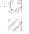
- the case where the position a1 of the object A is a non-transparent material that does not transmit light is compared with the case where the position a2 is a translucent material that transmits a part of light.
- the position a1 of the object A is a non-transparent material that does not transmit light
- the position a2 is a translucent material that transmits a part of light.
- substantially all of the infrared rays irradiated from the infrared irradiation unit 112 are reflected at the position a1.
- the reflection position a2 only a part of the infrared ray irradiated from the infrared irradiation unit 112 is reflected. Therefore, the reflected light intensity C1 of the reflected light at the position a1 is larger than the reflected light intensity C2 of the reflected light at the position a2.
- the position a1 is a position corresponding to the target object, and the position a2 is translucent.
- the reflected light intensity (C2) of the reflected light in the translucent container can be significantly smaller than the reflected light intensity (C1) of the reflected light in the target object.
- specific examples of the translucent container include a plastic bag for packaging fruits and vegetables in a supermarket or the like, or a container such as plastic whose contents can be visually confirmed.
- the information processing apparatus 130 is, for example, a computer.
- the information processing apparatus 130 includes a control unit 132 such as a CPU (Central Processing Unit) and a storage unit 134 such as a memory or a hard disk.
- the information processing apparatus 130 performs necessary processing such as object detection according to the information obtained by the distance sensor 110.
- the object detection unit 200 determines whether or not the object A is in a state where the target object is covered with a translucent container when the object A faces the distance sensor 110, as will be described later.
- the object A is in a state (first state) where the target object is covered with a translucent container indicates a state in which the target object is accommodated in the translucent container, for example. That is, at this time, the object A is composed of a translucent container and a target object.
- the object A is in a state where the target object is not covered by the translucent container (second state)” indicates a state in which the target object is not accommodated in the translucent container, for example. That is, at this time, the object A consists of only the target object.
- the intensity threshold Thc may be a maximum value that can be taken by the intensity of the reflected light reflected by the translucent container. That is, when the reflected light intensity at a certain pixel is equal to or higher than the intensity threshold Thc, the reflected light corresponding to the pixel can be light reflected by a non-transparent target object. In other words, when the reflected light intensity in a certain pixel is smaller than the intensity threshold Thc, the reflected light corresponding to the pixel can be light reflected by the translucent container.
- the target object determination unit 210 determines whether or not the area ratio S_Ac / S_Ad of the area S_Ac of the reflected light intensity area Ac to the area S_Ad of the distance area Ad is less than a predetermined threshold Thr (S110). Specifically, the target object determination unit 210 calculates the area S_Ad of the distance region Ad. This area S_Ad may correspond to the number of pixels included in the distance region Ad. Similarly, the target object determination unit 210 calculates the area S_Ac of the reflected light intensity region Ac. This area S_Ac may correspond to the number of pixels included in the reflected light intensity region Ac.
- the target object determination unit 210 calculates the area ratio S_Ac / S_Ad by dividing the area S_Ac by the area S_Ad. Then, the target object determination unit 210 compares the area ratio S_Ac / S_Ad with the threshold value Thr.
- process of the process execution control unit 212 can be appropriately determined according to an apparatus to which the object detection apparatus 100 according to the present embodiment is applied. Note that the process execution control unit 212 is not an essential component and may be incorporated in an arbitrary device connected to the object detection device 100.
- the threshold value Thr can be determined in consideration of the ratio of the target object that normally occupies the semi-transparent container on the surface facing the distance sensor 110.
- the threshold value Thr may be set to 1 ⁇ 2. Note that, for pixels corresponding to positions in the immediate vicinity of the target object, the reflected light intensity may increase due to diffraction or the like even though there is no actual target object. Therefore, the threshold Thr is preferably a value smaller than 1.
- FIG. 6A shows that the object A is the distance sensor 110 of the object detection device 100 when the object A is composed of the target object B and the translucent container C, and the target object B is covered with the translucent container C.
- An opposed state (first state) is shown.
- FIG. 6B shows that the object A (target object B) is the distance sensor 110 of the object detection device 100 when the object A is the target object B and the target object B is not covered with the translucent container.
- An opposed state (second state) is shown.
- FIG. 7A and 7B are diagrams illustrating the distance area Ad and the reflected light intensity area Ac acquired in the state of FIG. 6A, where FIG. 7A illustrates the distance area Ad, and FIG. 7B illustrates the reflected light intensity area. Illustrates Ac.
- the target object B and the translucent container C of the object A are located within the range S1 from the distance sensor 110. Therefore, the distance area acquisition unit 206 acquires a distance area Ad as illustrated in FIG.
- the distance area Ad is generated so as to indicate a position substantially corresponding to the translucent container C.
- region shown with the oblique line shown by D shows the position (background etc.) where the distance from the distance sensor 110 deviated from range S1. That is, there is no object around the translucent container C whose distance from the distance sensor 110 is within the range S1.
- the intensity of the reflected light reflected by the translucent container C is smaller than the intensity threshold Thc.
- the intensity of the reflected light that is transmitted through the translucent container C and reflected by the target object B is equal to or higher than the intensity threshold Thc.
- the target object B is covered with a translucent container C. Therefore, the reflected light intensity region acquisition unit 208 acquires the reflected light intensity region Ac as exemplified in FIG.
- the reflected light intensity region Ac is generated so as to indicate a position substantially corresponding to the target object B in the translucent container C.
- a hatched area indicated by E indicates a position outside the distance area Ad and a position within the distance area Ad but the reflected light intensity is less than the intensity threshold Thc.
- the target object determination unit 210 determines the area between the area S_Ad of the distance region Ad illustrated in FIG. 7A and the area S_Ac of the reflected light intensity region Ac illustrated in FIG.
- the ratio S_Ac / S_Ad is calculated.
- the area ratio S_Ac / S_Ad is smaller than a threshold value Thr (for example, 1/2). Therefore, the target object determination unit 210 determines that the target object B is covered with the translucent container C.
- FIG. 8A and 8B are diagrams illustrating the distance area Ad and the reflected light intensity area Ac acquired in the state of FIG. 6B, where FIG. 8A illustrates the distance area Ad, and FIG. 8B illustrates the reflected light intensity area. Illustrates Ac.
- the object A target object B
- the distance area acquisition unit 206 acquires a distance area Ad as illustrated in FIG.
- the distance area Ad indicates a position substantially corresponding to the target object B.
- region shown with the oblique line shown by D shows the position (background etc.) where the distance from the distance sensor 110 deviated from range S1. That is, there is no object around the target object B whose distance from the distance sensor 110 is within the range S1.
- the target object determination unit 210 determines the area between the area S_Ad of the distance region Ad illustrated in FIG. 8A and the area S_Ac of the reflected light intensity region Ac illustrated in FIG.
- the ratio S_Ac / S_Ad is calculated.
- the area ratio S_Ac / S_Ad is equal to or greater than a threshold value Thr (for example, 1/2). Therefore, the target object determination unit 210 determines that the target object B is not covered with the translucent container.
- the target object is covered with the translucent container. It is difficult to determine whether or not the object is covered with a translucent container simply by imaging the object and performing recognition processing on the object.
- the target object is covered by the translucent container using the distance to the object measured using the distance sensor 110 and the intensity of the reflected light reflected by the object. It is determined whether or not Therefore, when the target object is covered with a translucent container, a process suitable for the case where the target object is covered with a translucent container can be performed, and the target object is not covered with the translucent container. In some cases, it is possible to perform processing suitable when the target object is not covered with the translucent container.
- the second embodiment is different from the first embodiment in that recognition processing is performed on a target object. Note that components that are substantially the same as those in the first embodiment are given the same reference numerals, and descriptions thereof are omitted.
- FIG. 11 is a functional block diagram of the object detection apparatus 300 according to the second embodiment.
- FIG. 12 is a flowchart of a process performed by the object detection apparatus 300 according to the second embodiment.
- the object detection device 300 includes an object detection unit 320.
- the object detection unit 320 includes a distance image acquisition unit 202, a reflected light intensity image acquisition unit 204, a distance region acquisition unit 206, a reflected light intensity region acquisition unit 208, a target object determination unit 210, and an imaging control unit 324.
- the distance image acquisition unit 202 controls the distance sensor 110 to acquire a distance image in the same manner as the process of S102 (S202).
- the reflected light intensity image acquisition unit 204 controls the distance sensor 110 to acquire a reflected light intensity image, similarly to the process of S104 (S204).
- the distance area acquisition unit 206 acquires a distance area Ad whose distance from the distance sensor 110 is within the range S1 (first range) in the distance image, similarly to the process of S106 (S206).
- the reflected light intensity area acquisition unit 208 acquires the reflected light intensity area Ac in the reflected light intensity image whose reflected light intensity is equal to or greater than the intensity threshold Thc in the distance area Ad, similarly to the process of S108 (S208).
- the target object determination unit 210 determines whether or not the area ratio S_Ac / S_Ad of the area S_Ac of the reflected light intensity area Ac to the area S_Ad of the distance area Ad is less than a predetermined threshold Thr, similarly to the process of S110. Judgment is made (S210).
- the object detection unit 320 performs a recognition process when the target object is covered with a translucent container as described below (S212). ). Specifically, in this case, the target object determination unit 210 determines that the target object is covered with a translucent container. Then, the imaging control unit 324 controls the imaging unit 312 to cause the imaging unit 312 to capture a two-dimensional image including the image of the object A. Specifically, the imaging control unit 324 controls the imaging unit 312 to image the object A directed to the three-dimensional camera 310.
- the imaging control unit 324 acquires the two-dimensional image generated by the imaging unit 312 and outputs it to the target object image extraction unit 326.
- this two-dimensional image may include an image of a translucent container (when covered by a translucent container) and an image of a background (background image) in addition to the image of the target object.
- the imaging unit 312 and the distance sensor 110 are arranged close to each other, the two-dimensional image corresponds to the distance image and the reflected light intensity image.
- the target object recognition processing unit 328 performs target object recognition processing using the target object image extracted by the target object image extraction unit 326. Specifically, the target object recognition processing unit 328 performs pattern matching between the reference data related to the target object stored in the reference data storage unit 330 and the target object image.
- the reference data storage unit 330 stores reference data and object names in association with each other.
- the reference data storage unit 330 stores not only the reference data when the target object is not covered with the translucent container, but also the reference data when the target object is covered with the translucent container. .
- the target object recognition processing unit 328 determines that the target object is covered with the semi-transparent container. Pattern matching with the target object image is performed using the reference data.
- the object detection unit 320 performs a recognition process when the target object is not covered with the translucent container (S214). Specifically, in this case, the target object determination unit 210 determines that the target object is not covered with the translucent container (that is, the target object is exposed). Then, the imaging control unit 324 and the target object image extraction unit 326 each perform processing similar to the processing in S212, and a target object image is obtained.
- the target object recognition processing unit 328 performs target object recognition processing using the target object image extracted by the target object image extraction unit 326. Specifically, in S214, the target object determination unit 210 determines that the target object is not covered with the translucent container, so the target object recognition processing unit 328 is stored in the reference data storage unit 330. Pattern matching is performed between the reference data when the target object is not covered with the translucent container (that is, reference data regarding the object itself) and the target object image.
- the target object image includes an image of the target object that has passed through the translucent container. That is, in the target object image in this case, the color, streaks, or pattern of the translucent container is added so as to overlap the surface of the target object. Therefore, if the recognition process is not performed in consideration of the difference between the target object images due to the target object being covered with the translucent container, the recognition rate may decrease.
- the target object recognition processing unit 328 covers the target object with the semi-transparent container.
- the target object is recognized using the reference data.
- the target object recognition processing unit 328 uses the reference data when the target object is not covered with the semitransparent container.
- the target object is recognized. That is, the target object recognition processing unit 328 in the present embodiment distinguishes between a first state where the target object is covered with a semi-transparent container and a second state where the target object is not covered with a semi-transparent container. Separately, the target object recognition process is performed. Therefore, the recognition rate of the target object can be improved regardless of whether or not the target object is covered with the translucent container.
- the reference data is exemplified below.
- the reference data may be an image serving as a reference for an object (object reference image).
- the target object recognition processing unit 328 collates the extracted target object image with the object reference image. Then, the target object recognition processing unit 328 associates the target object with the object name corresponding to the object reference image when the similarity between the two satisfies an allowable value.
- the object reference image includes an image when the object is covered with a translucent container and an image when the object is not covered.
- the reference data may be data (object feature data) indicating a feature that serves as a reference of the target object.
- the object feature data includes, for example, information indicating the shape of the object, information indicating the color of the object, information indicating the texture (such as gloss) of the object, and information indicating character information and a pattern attached to the surface of the object. May be included.
- the target object recognition processing unit 328 extracts the feature of the image from the extracted target object image. Then, the target object recognition processing unit 328 collates the extracted image features with the object feature data. Then, the target object recognition processing unit 328 associates the target object with an object name corresponding to the object feature data when the similarity between the two satisfies an allowable value.
- the object feature data includes data indicating characteristics when the object is covered with a translucent container and data indicating characteristics when the object is not covered.
- the target object recognition processing unit 328 may recognize the object name by reading character information attached to the surface of the target object using an OCR (Optical Character Reader). In this case, the target object recognition processing unit 328 may appropriately change the accuracy of the OCR or the like depending on whether or not the target object is covered with a translucent container.
- OCR Optical Character Reader
- the reference data storage unit 330 provides not only the reference data when the target object is not covered with the semitransparent container, but also the reference when the target object is covered with the semitransparent container. Although data is also stored, it is not limited to such a configuration.
- the reference data storage unit 330 may store only the reference data when the target object is not covered with the translucent container.
- the target object recognition processing unit 328 performs target object recognition processing using the stored reference data. Do.
- the target object recognition processing unit 328 removes the difference caused by being covered with the semi-transparent container from the target object image. Then, the target object is recognized using the stored reference data.
- the target object recognition processing unit 328 reduces the RGB (Red-Green-Blue) luminance value of each pixel of the target object image. Then, pattern matching with the stored reference data may be performed.
- the target object recognition processing unit 328 may perform pattern matching after reducing the importance of the pattern of the object in the stored reference data. Further, for example, the target object recognition processing unit 328 determines that the streak-like image appearing in the target object image is a streak such as a plastic bag, removes the streak-like image, and stores the stored reference. Pattern matching with data may be performed.
- the target object recognition process is performed using the two-dimensional image of the target object photographed by the imaging unit 312.
- the target object recognition processing unit 328 may recognize the shape (outer shape) of the target object from the shape of the reflected light intensity region Ac.
- the target object recognition processing unit 328 may perform target object recognition processing by pattern matching between the outer shape of the target object and the outer shape of the object indicated in the reference data.
- the unevenness on the surface of the target object may be recognized from the distance value indicated by each pixel of the distance image corresponding to the reflected light intensity region Ac.
- the target object recognition processing unit 328 may perform target object recognition processing by pattern matching between the surface irregularities of the target object and the surface irregularities of the object indicated in the reference data.
- the recognition process can be performed using the color information of the target object by using the two-dimensional image, the recognition rate can be further improved.
- the third embodiment shows an application example of the object detection apparatus 300 according to the second embodiment. Note that components that are substantially the same as those in the first and second embodiments are denoted by the same reference numerals, and description thereof is omitted.
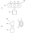
- FIG. 13 is a diagram illustrating a POS terminal device 400 according to the third embodiment.
- the POS terminal device 400 according to the third embodiment includes the object detection device 300 (the information processing device 130 and the three-dimensional camera 310) according to the second embodiment.
- the POS terminal device 400 includes a store clerk display operation unit 402, a customer display unit 404, an information processing device 130, and a three-dimensional camera 310 that is a product reading device.
- the POS terminal device 400 is placed, for example, on a counter stand (not shown), and the customer faces the left side of FIG. 13 and the store clerk faces the right side of the POS terminal device 400.
- the store clerk display operation unit 402 is, for example, a touch panel, an LCD (Liquid Crystal Display), or a keyboard.
- the store clerk display operation unit 402 displays information necessary for the store clerk and receives operations of the store clerk under the control of the information processing apparatus 130.
- the customer display unit 404 is, for example, a touch panel or an LCD.
- the customer display unit 404 displays information necessary for the customer under the control of the information processing apparatus 130.
- the display part 404 for customers may have an input device, and may receive a customer's operation as needed.
- the 3D camera 310 which is a product reading device is provided on the surface of the store clerk, and the product is directed when the product is imaged (read).
- the 3D camera 310 reads an image of the product.
- the POS terminal device 400 performs merchandise recognition processing.
- the POS terminal device 400 has the same function as the object detection unit 320 according to the second embodiment. That is, in the POS terminal device 400, as in the object detection device 300 according to the second embodiment, a product is covered with a translucent container using the distance image and the reflected light intensity image generated by the three-dimensional camera 310. It is determined whether or not. Then, the POS terminal device 400 performs a product recognition process by distinguishing between a first state in which the product is covered with the translucent container and a second state in which the product is not covered with the translucent container. Therefore, it is possible to improve the recognition rate of the product regardless of whether the product is covered with the translucent container.
- the imaging control unit 324 causes the imaging unit 312 to capture a two-dimensional image including the image of the object A in the process of S212 or S214.
- the configuration is limited to such a configuration. Absent. This imaging process may be performed at an arbitrary timing before the process of S210.
- the POS terminal device according to the third embodiment can be applied to, for example, a self-checkout.
- the structure concerning this Embodiment was applied to the POS terminal device, it is not restricted to this.
- the present invention can be applied to a general object recognition device such as an object recognition device used for sorting packages in a warehouse or the like, and a system including the object recognition device. It can also be applied to a robot that can recognize an object.
- the distance to the object is measured by the TOF method, but the configuration is not limited to this.
- the distance to the object may be realized by using a unit that measures using the parallax obtained by the two imaging units.
- both the distance and the reflected light intensity are measured using the distance sensor.
- the present invention is not limited to such a configuration.
- the means for measuring the distance may be a device using the above-described parallax, and the means for measuring the reflected light intensity may be separate from the device for measuring the distance.
- the means for measuring the distance may be a device using the above-described parallax, and the means for measuring the reflected light intensity may be separate from the device for measuring the distance.
- a distance sensor it is possible to measure both distance and reflected light intensity with a single device, so it is possible to suppress an increase in the number of devices. It is.
- the distance image generation unit 116 and the reflected light intensity image generation unit 118 are provided in the distance sensor 110, but the configuration is not limited thereto.
- at least one of the distance image generation unit 116 and the reflected light intensity image generation unit 118 may be realized by the information processing device 130.
- the distance sensor 110 outputs information indicating the measured distance and the corresponding position (pixel) and information indicating the reflected light intensity and the corresponding position (pixel) to the information processing apparatus 130, and information
- the processing device 130 may generate at least one of the distance image and the reflected light intensity image using the information.
- Non-transitory computer readable media include various types of tangible storage media (tangible storage medium).
- Examples of non-transitory computer-readable media include magnetic recording media (eg flexible disks, magnetic tapes, hard disk drives), magneto-optical recording media (eg magneto-optical discs), CD-ROMs (Read Only Memory), CD-Rs, CD-R / W, semiconductor memory (for example, mask ROM, PROM (Programmable ROM), EPROM (Erasable ROM), flash ROM, RAM (random access memory)) are included.
- the program may also be supplied to the computer by various types of temporary computer-readable media. Examples of transitory computer readable media include electrical signals, optical signals, and electromagnetic waves.
- the temporary computer-readable medium can supply the program to the computer via a wired communication path such as an electric wire and an optical fiber, or a wireless communication path.
Landscapes
- Physics & Mathematics (AREA)
- Engineering & Computer Science (AREA)
- General Physics & Mathematics (AREA)
- Electromagnetism (AREA)
- Remote Sensing (AREA)
- Radar, Positioning & Navigation (AREA)
- Computer Networks & Wireless Communication (AREA)
- Multimedia (AREA)
- Theoretical Computer Science (AREA)
- Geophysics And Detection Of Objects (AREA)
- Measurement Of Optical Distance (AREA)
- Investigating Materials By The Use Of Optical Means Adapted For Particular Applications (AREA)
- Investigating Or Analysing Materials By Optical Means (AREA)
- Cash Registers Or Receiving Machines (AREA)
Abstract
Description
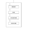
実施の形態の説明に先立って、本発明にかかる実施の形態の概要を説明する。図1は、本発明の実施の形態にかかる物体検出装置1の概要を示す図である。物体検出装置1は、距離計測部2(距離計測手段)と、照射部4(照射手段)と、反射光強度計測部6(反射光強度計測手段)と、対象物体判定部8(対象物体判定手段)とを有する。
以下、図面を参照して本発明の実施の形態について説明する。
図2は、実施の形態1にかかる物体検出装置100の外観を示す図であり、(A)は正面図を示し、(B)は側面図を示す。また、図3は、実施の形態1にかかる物体検出装置100のハードウェア構成を示す図である。
つまり、距離センサ110は、赤外線等の光線を照射し、照射された光線が物体Aの各位置まで往復するのにかかる時間から、距離を計測する。なお、本実施の形態では、赤外線が照射されるとしたが、これに限定されない。例えば、距離センサ110は、赤外線以外の波長域の光を利用してもよい。また、距離センサ110は、レーザで赤外線を発振してもよい。
つまり、物体Aの位置a1が距離画像の画素位置(X1,Y1)に対応する場合、位置a1は、反射光強度画像においても画素位置(X1,Y1)にほぼ対応する。言い換えると、距離センサ110によって得られた反射光強度画像の各画素位置は、距離画像の各画素位置と、互いに対応するように構成されている。
この場合、この集積回路を用いて、上記の各構成要素から構成されるプログラムを実現してもよい。このことは、後述する他の実施の形態においても同様である。
距離画像取得部202は、距離センサ110を制御して、距離画像を取得する(S102)。具体的には、距離画像取得部202は、対向する物体Aの距離画像を撮影するように、距離センサ110を制御する。距離センサ110は、距離画像取得部202の制御に応じて、距離センサ110に対向する物体Aの距離画像を撮影し、距離画像(距離画像を示す画像データ)を生成する。距離画像取得部202は、生成された距離画像を取得し、距離領域取得部206に出力する。
図6(A)は、物体Aが対象物体Bと半透明容器Cとからなり、対象物体Bが半透明容器Cに覆われている場合に、物体Aが物体検出装置100の距離センサ110に対向した状態(第1の状態)を示す。一方、図6(B)は、物体Aが対象物体Bからなり、対象物体Bが半透明容器に覆われていない場合に、物体A(対象物体B)が物体検出装置100の距離センサ110に対向した状態(第2の状態)を示す。
次に、実施の形態2について説明する。実施の形態2においては、対象物体について認識処理を行う点で、実施の形態1と異なる。なお、実施の形態1と実質的に同様の構成部分については同じ符号を付し、説明を省略する。
距離画像取得部202は、S102の処理と同様に、距離センサ110を制御して、距離画像を取得する(S202)。反射光強度画像取得部204は、S104の処理と同様に、距離センサ110を制御して、反射光強度画像を取得する(S204)。距離領域取得部206は、S106の処理と同様に、距離画像において距離センサ110からの距離が範囲S1(第1の範囲)内である距離領域Adを取得する(S206)。反射光強度領域取得部208は、S108の処理と同様に、距離領域Ad内で、反射光強度画像において反射光強度が強度閾値Thc以上である反射光強度領域Acを取得する(S208)。
対象物体判定部210は、S110の処理と同様に、距離領域Adの面積S_Adに対する反射光強度領域Acの面積S_Acの面積比S_Ac/S_Adが、予め定められた閾値Thr未満であるか否かを判断する(S210)。
次に、実施の形態3について説明する。実施の形態3は、実施の形態2にかかる物体検出装置300の適用例について示している。なお、実施の形態1及び実施の形態2と実質的に同様の構成部分については同じ符号を付し、説明を省略する。
なお、本発明は上記実施の形態に限られたものではなく、趣旨を逸脱しない範囲で適宜変更することが可能である。例えば、上述したフローチャートにおける処理の順序は、適宜、変更可能である。また、上述したフローチャートにおける複数の処理の少なくとも1つは、なくても構わない。例えば、図5のフローチャートにおいて、S102の処理は、S104の処理の後で行われてもよい。同様に、S104の処理は、S106の処理の後で行われてもよい。図12のフローチャートについても同様である。
但し、距離センサを用いて距離及び反射光強度の両方を測定することによって、1つのデバイスで、距離及び反射光強度の両方を測定することができるので、デバイス数の増加を抑制することが可能である。
この出願は、2014年2月24日に出願された日本出願特願2014-033028を基礎とする優先権を主張し、その開示の全てをここに取り込む。
2 距離計測部
4 照射部
6 反射光強度計測部
8 対象物体判定部
100 物体検出装置
110 距離センサ
112 赤外線照射部
114 赤外線受光部
116 距離画像生成部
118 反射光強度画像生成部
130 情報処理装置
132 制御部
134 記憶部
200 物体検出部
202 距離画像取得部
204 反射光強度画像取得部
206 距離領域取得部
208 反射光強度領域取得部
210 対象物体判定部
212 処理実行制御部
300 物体検出装置
310 3次元カメラ
312 撮像部
320 物体検出部
324 撮像制御部
326 対象物体画像抽出部
328 対象物体認識処理部
330 基準データ格納部
400 POS端末装置
Claims (18)
- 対向する物体の各位置までの距離をそれぞれ計測する距離計測手段と、
前記物体に光を照射する照射手段と、
前記照射手段によって照射された光が前記物体の各位置に反射した反射光の強度をそれぞれ計測する反射光強度計測手段と、
前記距離計測手段によって計測された距離と、前記反射光強度計測手段によって計測された反射光の強度とに基づいて、対象物体が半透明の容器に覆われているか否かを判定する対象物体判定手段と
を有する物体検出装置。 - 前記対象物体判定手段は、前記距離計測手段によって計測された距離が予め定められた第1の範囲内にある位置に対応する第1の領域と、前記反射光強度計測手段によって計測された反射光強度の強度が予め定められた強度閾値以上である位置に対応する第2の領域とに基づいて、前記対象物体が前記容器に覆われているか否かを判定する
請求項1に記載の物体検出装置。 - 前記対象物体判定手段は、前記第1の領域の面積に対する前記第2の領域の面積の比が予め定められた値未満の場合に、前記対象物体が前記容器に覆われていると判定する
請求項2に記載の物体検出装置。 - 前記照射手段を有し、前記照射手段を用いて前記物体までの距離を検出する距離センサ をさらに有する請求項1から3のいずれか1項に記載の物体検出装置。
- 対向する物体の各位置までの距離をそれぞれ計測する距離計測手段と、
前記物体に光を照射する照射手段と、
前記照射手段によって照射された光が前記物体の各位置に反射した反射光の強度をそれぞれ計測する反射光強度計測手段と、
前記距離計測手段によって計測された距離と、前記反射光強度計測手段によって計測された反射光の強度とに基づいて、対象物体が半透明の容器に覆われている第1の状態と、前記対象物体が前記容器に覆われていない第2の状態とを区別して、前記対象物体の認識処理を行う物体認識手段と
を有する物体検出装置。 - 前記物体認識手段は、前記距離計測手段によって計測された距離が予め定められた第1の範囲内にある位置に対応する第1の領域と、前記反射光強度計測手段によって計測された反射光強度の強度が予め定められた強度閾値以上である位置に対応する第2の領域とに基づいて、前記対象物体の認識処理を行う
請求項5に記載の物体検出装置。 - 前記物体認識手段は、前記第1の領域の面積に対する前記第2の領域の面積の比が予め定められた値未満の場合に、前記対象物体が半透明の容器に覆われている場合の認識処理を行う
請求項6に記載の物体検出装置。 - 前記対象物体を撮像して前記対象物体の画像を生成する撮像手段
をさらに有し、
前記物体認識手段は、前記撮像手段によって生成された前記対象物体の画像を用いて、前記対象物体の認識処理を行う
請求項5から7のいずれか1項に記載の物体検出装置。 - 前記物体認識手段は、前記対象物体が第1の状態にある場合、前記対象物体が前記第1の状態にあるときの当該対象物体の画像と、前記対象物体が前記第2の状態にあるときの当該対象物体の画像との差分に基づいて、前記対象物体の認識処理を行う
請求項5から8のいずれか1項に記載の物体検出装置。 - 対向する物体の各位置までの距離をそれぞれ計測する距離計測手段と、
前記物体に光を照射する照射手段と、
前記照射手段によって照射された光が前記物体の各位置に反射した反射光の強度をそれぞれ計測する反射光強度計測手段と、
前記距離計測手段によって計測された距離と、前記反射光強度計測手段によって計測された反射光の強度とに基づいて、商品が半透明の容器に覆われている第1の状態と、前記商品が前記容器に覆われていない第2の状態とを区別して、前記商品の認識処理を行う物体認識手段と
を有するPOS端末装置。 - 対向する物体の各位置までの距離をそれぞれ計測し、
前記物体に光を照射し、
前記照射された光が前記物体の各位置に反射した反射光の強度をそれぞれ計測し、
前記計測された距離と、前記計測された反射光の強度とに基づいて、対象物体が半透明の容器に覆われているか否かを判定する
物体検出方法。 - 前記計測された距離が予め定められた第1の範囲内にある位置に対応する第1の領域と、前記計測された反射光強度の強度が予め定められた強度閾値以上である位置に対応する第2の領域とに基づいて、前記対象物体が前記容器に覆われているか否かを判定する
請求項11に記載の物体検出方法。 - 前記第1の領域の面積に対する前記第2の領域の面積の比が予め定められた値未満の場合に、前記対象物体が前記容器に覆われていると判定する
請求項12に記載の物体検出方法。 - 対向する物体の各位置までの距離をそれぞれ計測し、
前記物体に光を照射し、
前記照射された光が前記物体の各位置に反射した反射光の強度をそれぞれ計測し、
前記計測された距離と、前記計測された反射光の強度とに基づいて、対象物体が半透明の容器に覆われている第1の状態と、前記対象物体が前記容器に覆われていない第2の状態とを区別して、前記対象物体の認識処理を行う
物体検出方法。 - 前記計測された距離が予め定められた第1の範囲内にある位置に対応する第1の領域と、前記計測された反射光強度の強度が予め定められた強度閾値以上である位置に対応する第2の領域とに基づいて、前記対象物体の認識処理を行う
請求項14に記載の物体検出方法。 - 前記第1の領域の面積に対する前記第2の領域の面積の比が予め定められた値未満の場合に、前記対象物体が半透明の容器に覆われている場合の認識処理を行う
請求項15に記載の物体検出方法。 - 対向する物体の各位置までの距離を取得するステップと、
前記物体に照射された光が前記物体の各位置に反射した反射光の強度を取得するステップと、
前記取得された距離と、前記取得された反射光の強度とに基づいて、対象物体が半透明の容器に覆われているか否かを判定するステップと
をコンピュータに実行させるプログラムを格納するプログラム記録媒体。 - 対向する物体の各位置までの距離を取得するステップと、
前記物体に照射された光が前記物体の各位置に反射した反射光の強度を取得するステップと、
前記取得された距離と、前記取得された反射光の強度とに基づいて、対象物体が半透明の容器に覆われている第1の状態と、前記対象物体が前記容器に覆われていない第2の状態とを区別して、前記対象物体の認識処理を行うステップと
をコンピュータに実行させるプログラムを格納するプログラム記録媒体。
Priority Applications (2)
| Application Number | Priority Date | Filing Date | Title |
|---|---|---|---|
| US15/120,927 US10534072B2 (en) | 2014-02-24 | 2015-02-19 | Object detection device, POS terminal device, object detection method, program, and program recording medium |
| JP2016503980A JP6520913B2 (ja) | 2014-02-24 | 2015-02-19 | 物体検出装置、pos端末装置、物体検出方法及びコンピュータプログラム |
Applications Claiming Priority (2)
| Application Number | Priority Date | Filing Date | Title |
|---|---|---|---|
| JP2014033028 | 2014-02-24 | ||
| JP2014-033028 | 2014-02-24 |
Publications (1)
| Publication Number | Publication Date |
|---|---|
| WO2015125478A1 true WO2015125478A1 (ja) | 2015-08-27 |
Family
ID=53877997
Family Applications (1)
| Application Number | Title | Priority Date | Filing Date |
|---|---|---|---|
| PCT/JP2015/000774 WO2015125478A1 (ja) | 2014-02-24 | 2015-02-19 | 物体検出装置、pos端末装置、物体検出方法、プログラム及びプログラム記録媒体 |
Country Status (3)
| Country | Link |
|---|---|
| US (1) | US10534072B2 (ja) |
| JP (1) | JP6520913B2 (ja) |
| WO (1) | WO2015125478A1 (ja) |
Cited By (2)
| Publication number | Priority date | Publication date | Assignee | Title |
|---|---|---|---|---|
| CN107450106A (zh) * | 2017-09-28 | 2017-12-08 | 北京小米移动软件有限公司 | 饮水安全提示方法、装置及智能水杯 |
| JP2018163096A (ja) * | 2017-03-27 | 2018-10-18 | 沖電気工業株式会社 | 情報処理方法および情報処理装置 |
Families Citing this family (6)
| Publication number | Priority date | Publication date | Assignee | Title |
|---|---|---|---|---|
| WO2017145152A1 (en) * | 2016-02-24 | 2017-08-31 | Superb Reality Ltd. | System and method for object differentiation in three-dimensional space |
| US9986151B1 (en) | 2016-03-02 | 2018-05-29 | Amazon Technologies, Inc. | Systems and methods for determining a depth or reflectance of objects |
| US9912861B1 (en) | 2016-03-02 | 2018-03-06 | Amazon Technologies, Inc. | Systems and methods for determining a depth or reflectance of objects |
| JP2017181291A (ja) * | 2016-03-30 | 2017-10-05 | 富士通株式会社 | 距離測定装置、距離測定方法及びプログラム |
| JP6873711B2 (ja) * | 2017-01-16 | 2021-05-19 | 東芝テック株式会社 | 商品認識装置 |
| US10915783B1 (en) * | 2018-12-14 | 2021-02-09 | Amazon Technologies, Inc. | Detecting and locating actors in scenes based on degraded or supersaturated depth data |
Citations (5)
| Publication number | Priority date | Publication date | Assignee | Title |
|---|---|---|---|---|
| JPH07168019A (ja) * | 1993-09-07 | 1995-07-04 | Omron Corp | 偏光ビームスプリッタ及び光学装置 |
| JPH07311312A (ja) * | 1994-03-25 | 1995-11-28 | Omron Corp | 光学式センサ装置 |
| JP2007033104A (ja) * | 2005-07-25 | 2007-02-08 | Keyence Corp | 透明フィルム検出装置 |
| JP2007221491A (ja) * | 2006-02-17 | 2007-08-30 | Keyence Corp | 光電センサ |
| WO2013033442A1 (en) * | 2011-08-30 | 2013-03-07 | Digimarc Corporation | Methods and arrangements for identifying objects |
Family Cites Families (7)
| Publication number | Priority date | Publication date | Assignee | Title |
|---|---|---|---|---|
| JPS4832556A (ja) | 1971-08-31 | 1973-04-28 | ||
| JP2001216571A (ja) * | 2000-02-03 | 2001-08-10 | Glory Ltd | 料金精算方法および装置 |
| JP2011128024A (ja) | 2009-12-17 | 2011-06-30 | Sharp Corp | 3次元撮像装置 |
| JP5804467B2 (ja) * | 2010-03-31 | 2015-11-04 | 北陽電機株式会社 | 信号処理装置、及び走査式測距装置 |
| WO2012115083A1 (ja) | 2011-02-21 | 2012-08-30 | パナソニック株式会社 | 空間情報検出装置 |
| KR101893771B1 (ko) * | 2012-05-10 | 2018-08-31 | 삼성전자주식회사 | 3d 정보 처리 장치 및 방법 |
| FR3048803B1 (fr) * | 2016-03-10 | 2018-04-06 | Antalios | Procede de determination automatique d'un niveau de remplissage d'un sac plastique et boitier pour la mise en œuvre d'un tel procede |
-
2015
- 2015-02-19 US US15/120,927 patent/US10534072B2/en active Active
- 2015-02-19 WO PCT/JP2015/000774 patent/WO2015125478A1/ja active Application Filing
- 2015-02-19 JP JP2016503980A patent/JP6520913B2/ja active Active
Patent Citations (5)
| Publication number | Priority date | Publication date | Assignee | Title |
|---|---|---|---|---|
| JPH07168019A (ja) * | 1993-09-07 | 1995-07-04 | Omron Corp | 偏光ビームスプリッタ及び光学装置 |
| JPH07311312A (ja) * | 1994-03-25 | 1995-11-28 | Omron Corp | 光学式センサ装置 |
| JP2007033104A (ja) * | 2005-07-25 | 2007-02-08 | Keyence Corp | 透明フィルム検出装置 |
| JP2007221491A (ja) * | 2006-02-17 | 2007-08-30 | Keyence Corp | 光電センサ |
| WO2013033442A1 (en) * | 2011-08-30 | 2013-03-07 | Digimarc Corporation | Methods and arrangements for identifying objects |
Cited By (3)
| Publication number | Priority date | Publication date | Assignee | Title |
|---|---|---|---|---|
| JP2018163096A (ja) * | 2017-03-27 | 2018-10-18 | 沖電気工業株式会社 | 情報処理方法および情報処理装置 |
| JP7062878B2 (ja) | 2017-03-27 | 2022-05-09 | 沖電気工業株式会社 | 情報処理方法および情報処理装置 |
| CN107450106A (zh) * | 2017-09-28 | 2017-12-08 | 北京小米移动软件有限公司 | 饮水安全提示方法、装置及智能水杯 |
Also Published As
| Publication number | Publication date |
|---|---|
| JP6520913B2 (ja) | 2019-05-29 |
| US20160370459A1 (en) | 2016-12-22 |
| US10534072B2 (en) | 2020-01-14 |
| JPWO2015125478A1 (ja) | 2017-03-30 |
Similar Documents
| Publication | Publication Date | Title |
|---|---|---|
| WO2015125478A1 (ja) | 物体検出装置、pos端末装置、物体検出方法、プログラム及びプログラム記録媒体 | |
| JP6222345B2 (ja) | Pos端末装置、posシステム、画像処理方法及びプログラム | |
| JP6191701B2 (ja) | Pos端末装置、商品認識方法及びプログラム | |
| JP6318557B2 (ja) | Pos端末装置、posシステム、画像処理方法及びプログラム | |
| US11386297B2 (en) | Learning data generation device, learning data generation method, and recording medium | |
| JP6172380B2 (ja) | Pos端末装置、posシステム、商品認識方法及びプログラム | |
| US20210342807A1 (en) | System and methods for automatic detection of product insertions and product extraction in an open shopping cart | |
| KR102096230B1 (ko) | 도착 레인으로 합병되는 이동 아이템의 출발 레인을 결정 | |
| JP7453137B2 (ja) | Pos端末装置および画像処理方法 | |
| US20140354775A1 (en) | Edge preserving depth filtering | |
| JP2016033694A (ja) | 物体認識装置及び物体認識プログラム | |
| TWI623899B (zh) | Object size comparison shopping system | |
| CA3140449A1 (en) | System and method for object recognition using 3d mapping and modeling of light | |
| JP6569762B2 (ja) | Pos端末装置、posシステム、画像処理方法及びプログラム | |
| JP5935118B2 (ja) | 物体検出装置および物体検出方法 | |
| JP7201020B2 (ja) | 情報処理装置、システム、画像処理方法及びプログラム | |
| CA3140443A1 (en) | Method and device for detecting a fluid by a computer vision application | |
| JP6388108B2 (ja) | Pos端末装置、posシステム、情報処理システム、画像認識方法、及び画像認識プログラム | |
| JPWO2015146084A1 (ja) | Pos端末、情報処理装置、ホワイトバランス調整方法およびプログラム | |
| JP6551712B2 (ja) | Pos端末装置、posシステム、情報処理システム、画像認識方法、及び画像認識プログラム | |
| US20220230340A1 (en) | System and method for object recognition using 3d mapping and modeling of light | |
| TWM549388U (zh) | 物體尺寸比對購物系統 |
Legal Events
| Date | Code | Title | Description |
|---|---|---|---|
| 121 | Ep: the epo has been informed by wipo that ep was designated in this application |
Ref document number: 15751328 Country of ref document: EP Kind code of ref document: A1 |
|
| ENP | Entry into the national phase |
Ref document number: 2016503980 Country of ref document: JP Kind code of ref document: A |
|
| WWE | Wipo information: entry into national phase |
Ref document number: 15120927 Country of ref document: US |
|
| NENP | Non-entry into the national phase |
Ref country code: DE |
|
| 122 | Ep: pct application non-entry in european phase |
Ref document number: 15751328 Country of ref document: EP Kind code of ref document: A1 |