WO2015123820A1 - 用于燃气轮机的燃料供应管线系统 - Google Patents
用于燃气轮机的燃料供应管线系统 Download PDFInfo
- Publication number
- WO2015123820A1 WO2015123820A1 PCT/CN2014/072246 CN2014072246W WO2015123820A1 WO 2015123820 A1 WO2015123820 A1 WO 2015123820A1 CN 2014072246 W CN2014072246 W CN 2014072246W WO 2015123820 A1 WO2015123820 A1 WO 2015123820A1
- Authority
- WO
- WIPO (PCT)
- Prior art keywords
- pressure
- control valve
- fuel supply
- line
- supply line
- Prior art date
Links
Classifications
-
- F—MECHANICAL ENGINEERING; LIGHTING; HEATING; WEAPONS; BLASTING
- F02—COMBUSTION ENGINES; HOT-GAS OR COMBUSTION-PRODUCT ENGINE PLANTS
- F02C—GAS-TURBINE PLANTS; AIR INTAKES FOR JET-PROPULSION PLANTS; CONTROLLING FUEL SUPPLY IN AIR-BREATHING JET-PROPULSION PLANTS
- F02C9/00—Controlling gas-turbine plants; Controlling fuel supply in air- breathing jet-propulsion plants
- F02C9/26—Control of fuel supply
- F02C9/46—Emergency fuel control
-
- F—MECHANICAL ENGINEERING; LIGHTING; HEATING; WEAPONS; BLASTING
- F02—COMBUSTION ENGINES; HOT-GAS OR COMBUSTION-PRODUCT ENGINE PLANTS
- F02C—GAS-TURBINE PLANTS; AIR INTAKES FOR JET-PROPULSION PLANTS; CONTROLLING FUEL SUPPLY IN AIR-BREATHING JET-PROPULSION PLANTS
- F02C7/00—Features, components parts, details or accessories, not provided for in, or of interest apart form groups F02C1/00 - F02C6/00; Air intakes for jet-propulsion plants
- F02C7/22—Fuel supply systems
- F02C7/228—Dividing fuel between various burners
-
- F—MECHANICAL ENGINEERING; LIGHTING; HEATING; WEAPONS; BLASTING
- F01—MACHINES OR ENGINES IN GENERAL; ENGINE PLANTS IN GENERAL; STEAM ENGINES
- F01D—NON-POSITIVE DISPLACEMENT MACHINES OR ENGINES, e.g. STEAM TURBINES
- F01D21/00—Shutting-down of machines or engines, e.g. in emergency; Regulating, controlling, or safety means not otherwise provided for
- F01D21/003—Arrangements for testing or measuring
-
- F—MECHANICAL ENGINEERING; LIGHTING; HEATING; WEAPONS; BLASTING
- F02—COMBUSTION ENGINES; HOT-GAS OR COMBUSTION-PRODUCT ENGINE PLANTS
- F02C—GAS-TURBINE PLANTS; AIR INTAKES FOR JET-PROPULSION PLANTS; CONTROLLING FUEL SUPPLY IN AIR-BREATHING JET-PROPULSION PLANTS
- F02C7/00—Features, components parts, details or accessories, not provided for in, or of interest apart form groups F02C1/00 - F02C6/00; Air intakes for jet-propulsion plants
- F02C7/22—Fuel supply systems
- F02C7/222—Fuel flow conduits, e.g. manifolds
-
- F—MECHANICAL ENGINEERING; LIGHTING; HEATING; WEAPONS; BLASTING
- F02—COMBUSTION ENGINES; HOT-GAS OR COMBUSTION-PRODUCT ENGINE PLANTS
- F02C—GAS-TURBINE PLANTS; AIR INTAKES FOR JET-PROPULSION PLANTS; CONTROLLING FUEL SUPPLY IN AIR-BREATHING JET-PROPULSION PLANTS
- F02C7/00—Features, components parts, details or accessories, not provided for in, or of interest apart form groups F02C1/00 - F02C6/00; Air intakes for jet-propulsion plants
- F02C7/22—Fuel supply systems
- F02C7/232—Fuel valves; Draining valves or systems
-
- F—MECHANICAL ENGINEERING; LIGHTING; HEATING; WEAPONS; BLASTING
- F02—COMBUSTION ENGINES; HOT-GAS OR COMBUSTION-PRODUCT ENGINE PLANTS
- F02C—GAS-TURBINE PLANTS; AIR INTAKES FOR JET-PROPULSION PLANTS; CONTROLLING FUEL SUPPLY IN AIR-BREATHING JET-PROPULSION PLANTS
- F02C7/00—Features, components parts, details or accessories, not provided for in, or of interest apart form groups F02C1/00 - F02C6/00; Air intakes for jet-propulsion plants
- F02C7/26—Starting; Ignition
- F02C7/264—Ignition
-
- F—MECHANICAL ENGINEERING; LIGHTING; HEATING; WEAPONS; BLASTING
- F02—COMBUSTION ENGINES; HOT-GAS OR COMBUSTION-PRODUCT ENGINE PLANTS
- F02C—GAS-TURBINE PLANTS; AIR INTAKES FOR JET-PROPULSION PLANTS; CONTROLLING FUEL SUPPLY IN AIR-BREATHING JET-PROPULSION PLANTS
- F02C9/00—Controlling gas-turbine plants; Controlling fuel supply in air- breathing jet-propulsion plants
- F02C9/26—Control of fuel supply
- F02C9/263—Control of fuel supply by means of fuel metering valves
-
- F—MECHANICAL ENGINEERING; LIGHTING; HEATING; WEAPONS; BLASTING
- F02—COMBUSTION ENGINES; HOT-GAS OR COMBUSTION-PRODUCT ENGINE PLANTS
- F02C—GAS-TURBINE PLANTS; AIR INTAKES FOR JET-PROPULSION PLANTS; CONTROLLING FUEL SUPPLY IN AIR-BREATHING JET-PROPULSION PLANTS
- F02C9/00—Controlling gas-turbine plants; Controlling fuel supply in air- breathing jet-propulsion plants
- F02C9/26—Control of fuel supply
- F02C9/28—Regulating systems responsive to plant or ambient parameters, e.g. temperature, pressure, rotor speed
-
- F—MECHANICAL ENGINEERING; LIGHTING; HEATING; WEAPONS; BLASTING
- F17—STORING OR DISTRIBUTING GASES OR LIQUIDS
- F17D—PIPE-LINE SYSTEMS; PIPE-LINES
- F17D1/00—Pipe-line systems
- F17D1/02—Pipe-line systems for gases or vapours
- F17D1/04—Pipe-line systems for gases or vapours for distribution of gas
-
- G—PHYSICS
- G05—CONTROLLING; REGULATING
- G05D—SYSTEMS FOR CONTROLLING OR REGULATING NON-ELECTRIC VARIABLES
- G05D16/00—Control of fluid pressure
- G05D16/20—Control of fluid pressure characterised by the use of electric means
- G05D16/2006—Control of fluid pressure characterised by the use of electric means with direct action of electric energy on controlling means
- G05D16/2013—Control of fluid pressure characterised by the use of electric means with direct action of electric energy on controlling means using throttling means as controlling means
-
- F—MECHANICAL ENGINEERING; LIGHTING; HEATING; WEAPONS; BLASTING
- F05—INDEXING SCHEMES RELATING TO ENGINES OR PUMPS IN VARIOUS SUBCLASSES OF CLASSES F01-F04
- F05D—INDEXING SCHEME FOR ASPECTS RELATING TO NON-POSITIVE-DISPLACEMENT MACHINES OR ENGINES, GAS-TURBINES OR JET-PROPULSION PLANTS
- F05D2220/00—Application
- F05D2220/30—Application in turbines
- F05D2220/32—Application in turbines in gas turbines
-
- F—MECHANICAL ENGINEERING; LIGHTING; HEATING; WEAPONS; BLASTING
- F05—INDEXING SCHEMES RELATING TO ENGINES OR PUMPS IN VARIOUS SUBCLASSES OF CLASSES F01-F04
- F05D—INDEXING SCHEME FOR ASPECTS RELATING TO NON-POSITIVE-DISPLACEMENT MACHINES OR ENGINES, GAS-TURBINES OR JET-PROPULSION PLANTS
- F05D2240/00—Components
- F05D2240/35—Combustors or associated equipment
-
- F—MECHANICAL ENGINEERING; LIGHTING; HEATING; WEAPONS; BLASTING
- F05—INDEXING SCHEMES RELATING TO ENGINES OR PUMPS IN VARIOUS SUBCLASSES OF CLASSES F01-F04
- F05D—INDEXING SCHEME FOR ASPECTS RELATING TO NON-POSITIVE-DISPLACEMENT MACHINES OR ENGINES, GAS-TURBINES OR JET-PROPULSION PLANTS
- F05D2270/00—Control
- F05D2270/30—Control parameters, e.g. input parameters
- F05D2270/301—Pressure
- F05D2270/3011—Inlet pressure
-
- F—MECHANICAL ENGINEERING; LIGHTING; HEATING; WEAPONS; BLASTING
- F05—INDEXING SCHEMES RELATING TO ENGINES OR PUMPS IN VARIOUS SUBCLASSES OF CLASSES F01-F04
- F05D—INDEXING SCHEME FOR ASPECTS RELATING TO NON-POSITIVE-DISPLACEMENT MACHINES OR ENGINES, GAS-TURBINES OR JET-PROPULSION PLANTS
- F05D2270/00—Control
- F05D2270/30—Control parameters, e.g. input parameters
- F05D2270/301—Pressure
- F05D2270/3013—Outlet pressure
-
- F—MECHANICAL ENGINEERING; LIGHTING; HEATING; WEAPONS; BLASTING
- F05—INDEXING SCHEMES RELATING TO ENGINES OR PUMPS IN VARIOUS SUBCLASSES OF CLASSES F01-F04
- F05D—INDEXING SCHEME FOR ASPECTS RELATING TO NON-POSITIVE-DISPLACEMENT MACHINES OR ENGINES, GAS-TURBINES OR JET-PROPULSION PLANTS
- F05D2270/00—Control
- F05D2270/30—Control parameters, e.g. input parameters
- F05D2270/301—Pressure
- F05D2270/3015—Pressure differential pressure
Definitions
- the present invention relates to a fuel supply line system for a gas turbine.
- the invention also relates to a gas turbine system having the fuel supply line system. Background technique
- the prior art In order to be able to operate safely of the fuel supply system, the prior art generally desires that all points of the entire fuel supply line system, particularly the weak point, will be above the safe pressure, which is greater than the highest pressure the system is facing. Although such a fuel supply system can ensure safe operation, all pipelines need to be designed to have a high pressure bearing capacity, causing an increase in cost. Especially for a wide variety of gas sources with different pressures, such as gas grids, such fuel supply systems need to maintain a high safety margin to accommodate the high cost of a large number of gas sources and set specific pressures for specific gas sources. A compromise between low flexibility of ability. Summary of the invention
- the present invention is directed to a fuel supply line system for a gas turbine that can effectively ensure safe operation in a simple manner.
- the present invention provides a fuel supply pipeline system for a gas turbine, The method includes: a control valve for controlling gas supplied to the gas turbine; a first line for connecting the gas source and the control valve; a second line for connecting the control valve and the gas turbine; and a monitoring device configured to Determining a pressure of the second line immediately after the control valve, that is, adjacent to an outlet of the control valve; and a controller configured to decrease when the pressure in the tube determined in the second line is greater than a pressure within the predetermined tube.
- the effective flow area of the control valve is described and preferably the control valve is closed.
- the total safe operation of the lines, in particular the weakened lines, of the fuel supply line system for the gas turbine can be effectively maintained in a simple manner.
- the fuel supply line system further includes a latching valve disposed upstream of the control valve, the fuel supply line system configured to close the latching valve when the determined pressure within the tube is greater than a predetermined in-line pressure.
- the fuel supply line system includes a plurality of the control valves connected in parallel, the fuel supply line system being configured to be adjacent to any of the control valve outlets, wherein the pressure in the second line determined in the second line is greater than the predetermined pressure in the tube Close all control valves.
- the fuel supply line system is configured to shut down the fuel supply line system when the determined pressure within the pipe is greater than a predetermined pressure within the pipe.
- the second line that is rated is more cost effective, while monitoring the pressure level by pressure monitoring
- the weaker second line always ensures safe operation of the weaker second line and thus the entire fuel supply line system.
- the system of the present invention is more cost effective, more flexible, more adaptable to a variety of gas networks with different pressure levels, and still operates safely.
- the monitoring device comprises a first pressure sensor disposed adjacent the outlet of the control valve at the second line, whereby it is possible to simply determine whether the pressure in the tube immediately following the control valve exceeds The maximum allowable working pressure of the second line.
- the monitoring device comprises a second pressure sensor and a calculation unit arranged in the first line, the calculation unit being configured to be based on the measured pressure and the control of the second pressure sensor
- the determined pressure drop in the tube is calculated by the pressure drop of the valve, thereby eliminating the need to separately provide a pressure sensor at the outlet of the control valve.
- the monitoring device further comprises a differential pressure sensor mounted on the control valve for detecting a pressure drop or pressure loss through the control valve, which provides a simple controlled valve Pressure drop determination means.
- the monitoring device is configured to detect an opening of the control valve, the calculation unit being configured to determine a pressure drop across the control valve based on an opening of the control valve, which provides a A simple and low-cost means of determining the pressure drop of a controlled valve, and eliminating the differential pressure sensor.
- Kv—CV the flow coefficient corresponding to the opening of the control valve
- T0 temperature of the fluid in the pipe, such as gas
- ⁇ mass flow value
- M the molar mass of the fluid in the tube, such as gas
- k the adiabatic index of the fluid in the pipeline, such as gas
- a flow meter having a pressure sensor is further provided in the second line, the monitoring device comprising a calculation unit configured to be based on the measured pressure of the pressure sensor of the flow meter and in control
- the pressure drop or pressure loss of the second line portion between the outlet of the valve and the flow meter is calculated to determine the pressure within the tube, which takes advantage of the conventional means typically provided in the line system, ie the flow meter, whereby It is omitted to separately set the pressure sensor at the outlet of the control valve.
- the inventors have found that although the flow meter is at a distance from the control valve outlet, the pressure in the second line of the adjacent control valve outlet can be effectively determined by the pressure sensor and calculation unit within the flow meter.
- 1 ⁇ line flow coefficient, characterizing the flow capacity, generally known or can be determined by one skilled in the art
- T0 the temperature value of the fluid in the pipeline, such as gas
- kv, T0, are constant or can be determined by those skilled in the art.
- a gas turbine system comprising: A fuel supply line system of the embodiment, and a gas turbine having a combustion chamber, at least one burner located within the combustion chamber, an air supply mechanism for supplying compressed air to the combustion chamber, and a turbine in communication with the combustion chamber.
- a power generating apparatus comprising: a gas turbine system according to the present invention and a generator driven by the gas turbine system.
- Figure 1 is a schematic illustration of a first embodiment of a gas turbine system in accordance with the present invention
- Figure 2 is a schematic illustration of a second embodiment of a gas turbine system in accordance with the present invention.
- Fig. 4 schematically shows a fourth embodiment of a gas turbine system in accordance with the present invention.
- 10-gas source 20-fuel supply pipeline system; 21-locking valve; 22-first control valve; 24-second control valve; 26-first flow meter; 28-second flow meter; 29-feed branch 30-first line; 31-second line; 3 ⁇ -second line part; 32-first pressure sensor; 32'-first pressure sensor; 34-second pressure sensor; 36-pressure difference sensor; - controller; 40 - gas turbine; 42 - compressor; 44 - combustion chamber; 46 - burner; 48 - turbine; 50 - generator; 100 - gas turbine system; 262 - gauge pressure sensor; 264 - pressure sensor; Temperature Sensor. detailed description
- the gas turbine system 100 includes a fuel supply line system 20 and a gas turbine (GT) 40.
- the fuel supply line system 20 is connected to a gas source 10, such as a gas network, in particular a natural gas network, and supplies the gas in a controlled manner It is supplied to the gas turbine 40.
- the gas turbine 40 includes an air supply mechanism for supplying air, a combustion chamber (CC) 44, a plurality of combustors 46 located within the combustion chamber 44, and a turbine 48 or turbine wheel.
- the air supply mechanism preferably includes a compressor 42 to supply compressed air to the combustion chamber 44 along arrow A as shown.
- the combustor 46 in the combustion chamber 44 is then coupled to the fuel supply line system 20 to produce hot gas by combustion of the combustion gas in the compressed air to propel the turbine 48 to rotate, and the exhaust gas is discharged along arrow B as shown schematically.
- the gas turbine system 100 is part of a power plant, such that the gas turbine 40, and in particular the turbine 48, drives the generator 50 to generate electricity.
- the gas turbine system 100 in accordance with the present invention may be adapted for any suitable application without departing from the scope of the invention.
- the fuel supply line system 20 in accordance with the present invention may be adapted for use with gas turbines having other configurations or compositions without departing from the scope of the present invention.
- a fuel supply line system 20 in accordance with the present invention is described, including a main line connected to a gas source 10 and a plurality of main lines connected to the main line, as shown in the figure, two parallel sub-lines, each A control valve, i.e., first and second control valves 22, 24, is provided in the secondary line for controlling the amount of fuel supplied to the burner 46.
- a control valve i.e., first and second control valves 22, 24
- the upstream line of the control valves 22, 24 is referred to herein as the first line 30, and the downstream line is referred to as the second line 31.
- the first line 30 upstream of each of the control valves 22, 24 includes a common main line and a portion of the respective sub-line that is upstream of the control valves 22, 24. As shown, there may be no further flow control or adjustment mechanisms downstream of the control valves 22, 24, i.e., the second line 31.
- a latching valve 21 or any suitable safety lockout is provided in the main line, i.e., in the first line upstream of all of the control valves 22, 24.
- a compressor (not shown:) may also preferably be disposed upstream of the latching valve 21 or between the gas source 10 and the fuel supply line system 20 for increasing the gas pressure, for example, when the gas turbine is started.
- first and second flow meters 26, 28 are each disposed in the second line 31 downstream of each of the first and second control valves 22, 24.
- the flow meters 26, 28 can be any suitable conventional flow meter, and in the illustrated embodiment, the flow meter can preferably include a gauge pressure sensor 262, a pressure sensor 264, and a temperature sensor 266.
- the second line 31 can include a plurality of feed branches 29 extending in parallel downstream of the flow meters 26, 28, each of which can be coupled to a fuel 46.
- each second line 31 can include 24 feed branches 29, which in turn can be evenly distributed with, for example, 24 The burners 46 in the combustion chamber 44 are connected.
- the first line 30 can include and preferably be constructed of a conduit having a first pressure bearing rating or a first pressure rating
- the second conduit 31 can include a second pressure bearing rating or a second pressure
- the graded conduit is preferably constructed therefrom, the first pressure bearing rating being greater than the second pressure bearing rating.
- the first pressure bearing rating is, for example, greater than PN 63, preferably greater than or equal to PN 63 and less than or equal to PN 250, more preferably greater than or equal to PN 63 and less than or equal to PN 150o.
- the second pressure bearing rating is, for example, less than or equal to PN 50 .
- it is less than or equal to PN50 and greater than or equal to PN20, preferably less than or equal to PN40 and greater than or equal to PN20.
- the fuel supply line system 20 can also include at least one first pressure sensor 32, 32 immediately downstream of each of the control valves 22, 24, such as, in one embodiment, three first pressure sensors as monitoring means.
- the fuel supply line system 20 also includes a controller 38.
- the first pressure sensor 32, 32' is configured to detect the pressure in the tube in the second line 31 at the outlet of the control valves 22, 24.
- the first pressure sensor is preferably an absolute pressure sensor.
- the controller 38 can be configured to obtain the pressure measured by the first pressure sensor 32, 32' (only the first pressure sensor 32 is shown). For example, when the in-line pressure measured in the second line downstream of any of the control valves is unintentionally opened by the control valve 22 and/or 24, the controller 38 can reduce or close the effective flow area of the corresponding control valve.
- the pipeline system 20 of the present invention can be adapted to a wide variety of pressures by selecting a relatively high pressure level first line upstream of the control valve.
- a horizontal gas source in particular a gas network, wherein the pressure levels of the different gas grids are generally uncontrolled by the user, as known to those skilled in the art, and vary depending on the gas supplier and the municipal gas network configuration;
- a second line downstream of the control valve may be selected based on the specific gas turbine power; and the lower pressure level of the second line is determined by means of the in-pipe pressure monitoring means adjacent to the control valve The safe operation pressure of the two pipelines.
- the pipeline sections before and after the control valve can be based on their respective The core influencing factors are independently constructed "differentiated" so that a second pipeline with a relatively long length of low pressure can be used to obtain better cost-effectiveness, while at the same time ensuring safe operation of the entire fuel supply pipeline system through pressure monitoring means. .
- the system of the present invention is more cost effective, more flexible, more adaptable to a variety of gas networks with different pressure levels, and still operates safely.
- the embodiment shown in Fig. 2 is substantially similar to the embodiment shown in Fig. 1, except that the embodiment shown in Fig. 2 does not provide a first pressure sensor 32, 32' at the outlet of the control valves 22, 24.
- the monitoring device of this embodiment comprises at least one second pressure sensor 34 located in the first line 30, in particular upstream of the latching valve 21, for example three second pressure sensors and mounted on the control valves 22, 24
- the differential pressure sensor 36 is on.
- the second pressure sensor 34 can be a pressure sensor that is specifically designed to perform in-pipe pressure monitoring in accordance with the present invention, or a pressure sensor that is conventionally disposed in the main line, which reduces the cost of the line system.
- Dp—CV pressure drop or pressure loss detected by the differential pressure sensor.
- the pressure drop across the latching valve 21 is also contemplated.
- the pressure drop across the latching valve is not considered to provide a further safety margin.
- Kv—CV the flow coefficient corresponding to the opening of the control valve
- T0 temperature of the fluid in the pipe, such as gas
- M the molar mass of the fluid in the tube, such as gas
- k the thermal insulation index of the fluid in the pipe, such as gas
- the pressure in the tube of the second line downstream of the control valves 22, 24 is calculated using the pressure sensors 264 of the existing flow meters 26, 28.
- the computing unit can be configured to determine based on the measured pressure of the pressure sensor 264 of the flow meter 26, 28 and the pressure drop of the second line portion 31 ' between the outlet of the control valve 22, 24 and the flow meter 26, 28. The pressure inside the tube.
- the inventors have found that although the flow meters 26, 28 are at a distance from the control valves 22, 24, the pressure waves are sufficiently fast to obtain pressure signals from the pressure sensors of the flow meters 26, 28 in time to close the control valve and lock. Valve or shut down the pipeline system.
- the in-pipe pressure of the second line immediately downstream of the control valves 22, 24 is determined based on:
- dp_PIPE-max pressure drop or pressure loss of the second line portion determined based on the maximum allowable pressure of the second line.
- the pressure drop or pressure loss of the second line portion 31' is set to a fixed value, i.e., the maximum pressure loss described above.
- the pressure within the tube can be determined based on the dynamic pressure drop or pressure loss of the second line portion.
- the in-line pressure of the second line immediately downstream of the control valves 22, 24 is determined based on:
- P P3-dp_PIPE ;
- T0 fluid temperature value in the pipeline
Landscapes
- Engineering & Computer Science (AREA)
- Chemical & Material Sciences (AREA)
- Combustion & Propulsion (AREA)
- Mechanical Engineering (AREA)
- General Engineering & Computer Science (AREA)
- Physics & Mathematics (AREA)
- Fluid Mechanics (AREA)
- General Physics & Mathematics (AREA)
- Automation & Control Theory (AREA)
- Feeding And Controlling Fuel (AREA)
Abstract
一种用于燃气轮机(40)的燃料供应管线系统(200),包括:用于控制输送至所述燃气轮机的燃气的控制阀(22,24);用于连接燃气源(10)和所述控制阀(22,24)的第一管线;用于连接所述控制阀(22,24)和燃气轮机(40)的第二管线;监测装置,配置成用于确定所述第二管线在邻近所述控制阀出口处的管内压力;和控制器(38),配置成在所述第二管线中确定的管内压力大于预定管内压力时减小所述控制阀(22,24)的有效流通面积或关闭所述控制阀(22,24)。
Description
用于燃气轮机的燃料供应管线系统
技术领域
本发明涉及用于燃气轮机的燃料供应管线系统。 本发明还涉及具有该燃 料供应管线系统的燃气轮机系统。 背景技术
轮机、 例如燃气轮机 (GT)是一种以连续流动的流体为工质带动涡轮高速 旋转以用于输出动力的动力机械, 被广泛应用于众多工业领域, 如运载工具 推进、 发电站、 石化领域等。
为给燃气轮机供应燃气, 通常设置有燃料供应系统以从燃气源、 尤其是 燃气网获取燃气、 如天然气, 并将其供应到燃气轮机的燃烧室、 尤其是燃烧 室内的燃烧器。 例如, 本申请人的 WO2012/072614公开一种燃气轮机系统, 其燃料供应系统包括连接燃气网的主燃料管道和连接第一燃料管道和燃烧室 的并行的燃料部段, 其中在主燃料管道中设置有作为安全闭锁装置的第一阀, 在并行的燃料部段中分别设置有作为控制阀的第二阀和第三阀, 其全文通过 援引加入本文。
为了能够燃料供应系统的安全运行, 现有技术通常希望将整个燃料供应 管线系统的所有点、 尤其是薄弱点的承压能力均在安全压力之上, 该安全压 力大于系统所面临的最高压力。 虽然这样的燃料供应系统能够保证安全运行, 但是全部管线均需要设计成有较高的承压能力, 引起成本上升。 尤其是针对 具有不同压力的多种多样的燃气源、 如燃气网时, 这样的燃料供应系统需要 在保持高安全裕量来适应大量的燃气源的高成本和针对具体燃气源设定具体 承压能力的低灵活性之间折衷。 发明内容
本发明旨在提供一种能以简单的方式有效保证安全运行的用于燃气轮机 的燃料供应管线系统。
本发明另一目的是提供一种具有该燃料供应管线系统的燃气轮机系统。 为实现上述目的, 本发明提出了一种用于燃气轮机的燃料供应管线系统,
包括: 用于控制输送至所述燃气轮机的燃气的控制阀; 用于连接燃气源和所 述控制阀的第一管线; 用于连接所述控制阀和燃气轮机的第二管线; 监测装 置, 配置成确定第二管线在紧跟在所述控制阀后、 即邻近控制阀的出口处的 管内压力; 和控制器, 配置成在所述第二管线中确定的管内压力大于预定管 内压力时减小所述控制阀的有效流通面积且优选关闭所述控制阀。 人们明白, 在紧跟所述控制阀后所确定的管内压力大于预定管内压力时, 作为关闭该控 制阀的补充或替代, 也可以设置单独的流量控制机构来关闭该控制阀后的第 二管线或减小该第二管线的流量, 这落入本发明的范围内。 此外, 人们将可 明白, 根据本发明的控制阀将包括任何合适的流量调节机构。 在本发明所述 的实施例中, 紧跟所述控制阀后或者邻近控制阀的出口具有明确的工程上的 意义, 并能为本领域技术人员所理解, 例如是在第二管线上距控制阀出口的 约 9倍第二管道公称内径的距离内、 优选在约 3倍管道公称内径至 9倍管道 公称内径的距离、 优选距控制阀出口约 6倍管道公称内径的距离, 且有利地 在控制阀出口后、 在第二管线内大致出现最大管内压力的位置处。
通过本发明的技术方案, 能够以简单的方式有效地保持用于燃气轮机的 燃料供应管线系统的管线、 尤其是薄弱部位的管线的总能安全运行。
优选地, 该燃料供应管线系统还包括设置在所述控制阀上游的闭锁阀, 所述燃料供应管线系统配置成在所确定的管内压力大于预定管内压力时关闭 所述闭锁阀。 更优选地, 该燃料供应管线系统包括多个并联的所述控制阀, 所述燃料供应管线系统配置成邻近任一所述控制阀出口的在第二管线中确定 的管内压力大于预定管内压力时关闭所有控制阀。 特别优选地, 所述燃料供 应管线系统配置成在所确定的管内压力大于预定管内压力时使该燃料供应管 线系统停机。
根据本发明的一个特别优选的实施例, 所述第一管线具有第一压力承受 等级、 有时也称 "压力等级", 所述第二管线具有小于所述第一压力承受等级 的第二压力承受等级。 通过本发明的 "差异化"压力承受等级管线布置和管 内压力监控的结合, 可以根据影响控制阀前和后的管线部分的设计参数的相 应核心因素, 即就第一管线而言的燃气源、 如燃气网的压力水平和就第二管 线而言的燃气轮机驱动功率, "差异化"地构造控制阀前后的管线, 尤其分别 设计合适的管线压力承受等级, 从而可以通过长度较长的、 低压力承受等级 的第二管线获得更佳的成本效益, 而同时通过压力监控手段来监控压力等级
较弱的第二管线来始终保证较弱的第二管线并进而整个燃料供应管线系统的 安全运行。 相比于现有技术, 本发明的系统更节省成本、 更具灵活性、 更能 适应具有不同压力等级的多种燃气网、 且仍能安全运行。
根据本发明的另一优选实施例, 该预定管内压力基于所述第二压力承受 等级确定且小于或等于所述第二压力承受等级。
根据本发明的一个优选实施例, 所述第一压力承受等级大于等于 PN63 , 所述第二压力承受等级小于等于 PN50且大于等于 PN20。
根据本发明的一个实施例, 所述监测装置包括邻近所述控制阀的出口设 置在所述第二管线处的第一压力传感器, 由此可以简单地确定紧跟控制阀后 的管内压力是否超过第二管线的最大允许工作压力。
根据本发明的另一实施例, 所述监测装置包括设置在所述第一管线中的 第二压力传感器和计算单元, 所述计算单元配置成基于所述第二压力传感器 的测量压力和经控制阀的压降计算所述确定的管内压力, 由此可省去在控制 阀出口单独设置压力传感器。
根据进一歩优选的实施例, 所述监测装置还包括在所述控制阀上安装的 压差传感器, 用于检测经控制阀的压降或压力损失, 这提供了一种简单的经 控制阀的压降确定手段。
根据另一优选实施例, 所述监测装置配置成检测所述控制阀的开度, 所 述计算单元配置成根据所述控制阀的开度确定经所述控制阀的压降, 这提供 了一种简单且低成本的经控制阀的压降确定手段, 且省去了压差传感器。
优选地, 为了能准确确定经控制阀的压降或压力损失, 所述计算单元配 置成基于经典流体力学控制阀压降计算公式如下式但不限于下式确定经控制 阀的压降或压力损失: τοχζ
: m Kv CV x ΙΙΟ χ χ F t) χ ,
dp— CV=压降,
Kv— CV=控制阀开度所对应的流量系数,
T0=管内流体、 如燃气的温度值,
^ =质量流量值,
M=管内流体、 如燃气的摩尔质量,
k=管线内流体、 如燃气的绝热指数,
Χτ=控制阀的差压比例参数,
Fp=管线布置影响因子,
Z=管线内流体、 如燃气的可压缩因子,
其中, T0、 ^、 M、 k、 XT、 Fp、 Z为常数或能由本领域技术人员所确定。 根据另一优选实施例, 在所述第二管线中还设置具有压力传感器的流量 计, 所述监测装置包括计算单元, 该计算单元配置成基于所述流量计的压力 传感器的测量压力和在控制阀的出口到所述流量计之间的第二管线部分的压 降或压力损失计算所确定的管内压力, 这充分利用了管线系统中通常设有的 常规装置、 即流量计, 由此这可省去在控制阀出口单独设置压力传感器。 并 且, 发明人发现, 尽管流量计距控制阀出口有一段距离, 但仍可通过该流量 计内的压力传感器和计算单元有效确定邻近控制阀出口的在第二管线中的管 内压力。
优选地, 所述第二管线部分的压降为基于第二管线的最大允许压力所确 定的该第二管线部分的压降, 这提供了一种简单手段来确定第二管线部分的 压降。
作为替代, 为了能够更准确地确定第二管线部分的压降, 所述第二管线 部分的压降基于下式计算出:
 其中, dp— PIPE =该第二管线部分的压降,
P3=流量计的压力传感器检测到的压力测量值,
1^=管线流量系数, 表征通流能力, 一般为已知的或能由本领域技术人员 确定,
T0=管线内流体、 如燃气的温度值,
^ =质量流量值,
=标准密度,
其中, kv、 T0、 、 为常数或能由本领域技术人员所确定。
根据本发明的另一方案, 提供一种燃气轮机系统, 包括: 根据本发明实
施例的燃料供应管线系统, 和燃气轮机, 具有燃烧室、 位于燃烧室内的至少 一个燃烧器、 用于向燃烧室供应压缩空气的空气供应机构和与燃烧室相连通 的涡轮。
根据本发明的另一方案, 提供一种发电设备, 包括: 根据本发明的燃气 轮机系统和被所述燃气轮机系统驱动的发电机。
本发明的一部分优点和特征将能由本领域技术人员在阅读本发明后明 白, 另一部分在下文的具体实施方式中进行说明。 附图说明
以下附图仅旨在于对本发明做示意性说明和解释, 并不限定本发明的范 围。 其中,
图 1示意性示出了根据本发明的燃气轮机系统的第一实施例;
图 2示意性示出了根据本发明的燃气轮机系统的第二实施例;
图 3示意性示出了根据本发明的燃气轮机系统的第三实施例;
图 4示意性示出了根据本发明的燃气轮机系统的第四实施例。
在本发明的附图中, 相同或相似的附图标记将表示相同或相似的特征或 元件。
附图标记列表
10-燃气源; 20-燃料供应管线系统; 21-闭锁阀; 22-第一控制阀; 24-第二控制 阀; 26-第一流量计; 28-第二流量计; 29-供料支管; 30-第一管线; 31-第二管 线; 3 Γ-第二管线部分; 32-第一压力传感器; 32'-第一压力传感器; 34-第二 压力传感器; 36-压差传感器; 38-控制器; 40-燃气轮机; 42-压缩机; 44-燃烧 室; 46-燃烧器; 48-涡轮; 50-发电机; 100-燃气轮机系统; 262-表压传感器; 264-压力传感器; 266-温度传感器。 具体实施方式
现参考下文具体实施方式和附图来描述本发明的系统和设备的实施例。 尽管提供附图是为了呈现本发明的一些实施例, 但附图不必按实施例的具体 特征的尺寸绘制, 某些特征可被放大、 移除或剖切, 以便更好地示出本发明。
参考图 1, 示出了根据本发明的燃气轮机系统 100的实施例。该燃气轮机 系统 100包括燃料供应管线系统 20和燃气轮机 (GT)40。 该燃料供应管线系统 20与燃气源 10、 如燃气网、 尤其是天然气网相连, 并且以可控的方式将燃气
供应至燃气轮机 40。该燃气轮机 40包括用于供应空气的空气供应机构、燃烧 室 (CC)44、 位于燃烧室 44内的多个燃烧器 46以及涡轮 48或透平叶轮。 该空 气供应机构优选包括压缩机 42以将压缩空气如图所示沿箭头 A供应到燃烧室 44。 燃烧室 44内的燃烧器 46则与燃料供应管线系统 20相连, 从而借助于燃 气在压缩空气中燃烧产生热气以推动涡轮 48转动, 且排废气如图示意性所示 沿箭头 B排出。 在所示的实施例中, 该燃气轮机系统 100作为发电设备的一 部分, 从而燃气轮机 40、 具体而言是涡轮 48驱动发电机 50, 以产生电力。 但人们应想到, 根据本发明的燃气轮机系统 100可适用于任何合适的应用, 而不背离本发明的范围。 人们同样可以想到, 根据本发明的燃料供应管线系 统 20可适用于具有其他配置或组成的燃气轮机, 而不背离本发明的范围。
继续参考图 1, 现进一歩描述根据本发明的燃料供应管线系统 20, 包括 与燃气源 10连接的主管线和连接主管线的多个、 如图所示为两条并行的副管 线, 在每个副管线中设置有一控制阀, 即第一和第二控制阀 22、 24, 用于控 制被供应至燃烧器 46的燃料量。 尽管在所示的实施例中具有两条并行的副管 线以及进而两个控制阀 22、 24, 但人们可以想到, 可以仅具有一个控制阀 (即 不具有并行管线)或者具有多于两个的控制阀, 这都落入本发明的范围。 为描 述发明思想起见, 在本文中将控制阀 22、 24上游管线称作第一管线 30, 而将 下游管线称作第二管线 31。 由此, 在所示实施例中, 控制阀 22、 24各自上游 的第一管线 30包括共用的主管线和各自副管线中位于控制阀 22、 24上游的 部分。 如图所示, 在控制阀 22、 24下游, 即第二管线 31 中尤其可不具有进 一歩的流量控制或调节机构。
在所示的实施例中, 在主管线中, 即在所有控制阀 22、 24上游的第一管 线中设置有闭锁阀 21或任何合适的安全闭锁装置。 一压缩机 (图中未示出:)还 可优选地设置在闭锁阀 21上游或位于燃气源 10和燃料供应管线系统 20之间, 用于例如在燃气轮机启动时提高燃气压力。
在第一和第二控制阀 22、 24各自下游的第二管线 31 中还可优选各自设 置第一和第二流量计 26、 28。该流量计 26、 28可以是任何合适的常规流量计, 且在所示的实施例中, 该流量计优选可包括表压传感器 262、 压力传感器 264 和温度传感器 266。第二管线 31可包括在流量计 26、 28下游并行延伸的多条 供料支管 29, 每个供料支管 29可以与一个燃料器 46连接。 在所示的实施例 中, 每个第二管线 31可包括 24条供料支管 29, 其进而可与例如 24个均布在
燃烧室 44内的燃烧器 46连接。
仍参考图 1, 描述根据本发明的 "差异化"压力承受等级管线布置和管内 压力监控或说最大工作压力 (MOP)监控的结合。
在所示的实施例中, 第一管线 30可包括具有第一压力承受等级或第一压 力等级的管道且优选由其构成, 而第二管线 31可包括具有第二压力承受等级 或第二压力等级的管道且优选由其构成, 该第一压力承受等级大于第二压力 承受等级。在根据本发明的实施例中,所述第一压力承受等级例如大于 PN63 , 优选大于等于 PN63且小于等于 PN250, 更优选地大于等于 PN63且小于等于 PN150o 所述第二压力承受等级例如小于等于 PN50, 优选小于等于 PN50且 大于等于 PN20, 优选小于等于 PN40且大于等于 PN20。
该燃料供应管线系统 20还可包括紧跟在各控制阀 22、 24下游的至少一 个第一压力传感器 32、 32,、 例如在一个实施例中为三个第一压力传感器作为 监测装置。 该该燃料供应管线系统 20还包括控制器 38。 该第一压力传感器 32、 32'配置成检测控制阀 22、 24的出口处的第二管线 31中的管内压力。 该 第一压力传感器优选是绝对压力传感器。 该控制器 38可配置成可获得第一压 力传感器 32、 32' (图中仅显示获得第一压力传感器 32)所测量的压力。 例如在 无意打开控制阀 22和 /或 24使得任一控制阀下游的第二管线中测定的管内压 力大于预定管内压力时, 该控制器 38可使相应的控制阀的有效流通面积减小 或关闭、 或优选使得并联的一些且优选全部控制阀关闭和 /或使闭锁阀关闭, 更优选地使得该燃料供应管线系统 20并进而整个燃气轮机系统 100停机, 此 时所有控制阀 22、 24以及闭锁阀 21关闭。 在所示的实施例中, 该预定管内 压力是基于第二压力等级确定的, 且小于等于该第二压力等级。 优选地, 该 预定管内压力为第二压力等级减去一固定的或可变的安全裕量。
通过本发明的 "差异化"压力承受等级管线布置和管内压力监控的结合, 可以通过选择相对高压力等级的、 位于控制阀上游的第一管线, 本发明的管 线系统 20可以适合多种多样压力水平的燃气源, 尤其是燃气网, 其中不同的 燃气网的压力水平如本领域技术人员所知地通常是不受用户控制, 且取决于 燃气供应商以及市政燃气网络配置而各不相同; 同时, 可以基于具体的燃气 轮机功率, 选择较低压力等级的、 位于控制阀下游的第二管线; 此外, 还借 助于紧邻控制阀的管内压力监控手段, 基于第二管线的较低压力等级来确定 第二管线的安全运行压力。 由此, 控制阀前和后的管线部分可以基于各自的
核心影响因素来 "差异化"地独立构造, 从而可以通过长度相对更长的低压 力等级的第二管线获得更佳的成本效益, 而同时通过压力监控手段始终保证 整个燃料供应管线系统的安全运行。 相比于现有技术, 本发明的系统更节省 成本、 更具灵活性、 更能适应具有不同压力等级的多种燃气网、 且仍能安全 运行。
作为图 1 示出了根据本发明的一个实施例的监测装置的补充或替代, 在 图 2-4中示出了根据本发明的其他管内压力监控手段的实施例。
图 2所示的实施例基本类似于图 1所示的实施例, 除了图 2所示的实施 例未在控制阀 22、 24出口处设置第一压力传感器 32、 32'。 相比之下, 该实 施例的监测装置包括位于第一管线 30、具体地位于闭锁阀 21上游中的至少一 个第二压力传感器 34、例如三个第二压力传感器以及安装在控制阀 22、 24上 的压差传感器 36。人们将明白, 该第二压力传感器 34可以是为进行根据本发 明的管内压力监控而特设的压力传感器, 也可以为在主管线中常规设置的压 力传感器, 后者降低了管线系统的成本。 同样, 压差传感器 36可以为控制阀 22、 24自带的压差传感器。 在该实施例中, 紧跟控制阀 22、 24下游的第二管 线的管内压力可以通过例如独立的或如图所示集成在该控制器 38内的一计算 单元由下式计算出:
P=P0-dp_CV;
其中, P=确定的管内压力,
P0=第二压力传感器检测到的压力测量值,
dp— CV=压差传感器检测到的压降或压力损失。
在一个实施例中, 还可考虑经闭锁阀 21的压降。 但在优选的实施例中, 不考虑经该闭锁阀的压降, 以提供进一歩的安全裕量。
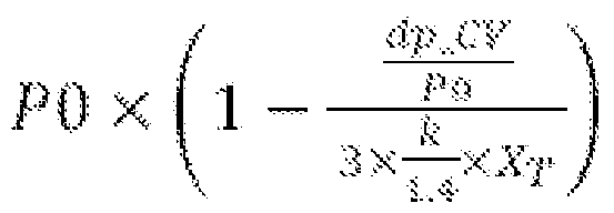
如图 3所示的再一实施例中, 监测装置可以不设置经控制阀 22、 24的压 差传感器, 该控制器 38可以检测各控制阀 22、 24的开度 (图中仅示出检测控 制阀 22 并基于控制阀 22、 24的开度确定经控制阀 22、 24的压降或压力损 失。
更优选地, 经控制阀 22、 24的压降或压力损失可通过计算单元经下式计 算出:
 其中, P0=第二压力传感器检测到的压力,
dp— CV=压降,
Kv— CV=控制阀开度所对应的流量系数,
T0=管内流体、 如燃气的温度值,
^ =质量流量值,
M=管内流体、 如燃气的摩尔质量,
k=管内流体、 如燃气的绝热指数,
Χτ=控制阀的差压比例参数,
Fp=管线布置影响因子,
Z=管内流体、 如燃气的可压缩因子,
其中, T0、 ^、 M、 k、 XT、 Fp、 Z为常数或能由本领域技术人员所确定。 在如图 4所示的又一实施例中, 利用已有的流量计 26、 28的压力传感器 264计算紧跟在控制阀 22、 24下游的第二管线的管内压力。 计算单元可配置 成基于所述流量计 26,28的压力传感器 264的测量压力和在控制阀 22,24的出 口和所述流量计 26,28之间的第二管线部分 31 '的压降确定该管内压力。 本发 明人发现, 尽管流量计 26、 28距离控制阀 22、 24具有一段距离, 但是压力 波的速度快到足以能及时从流量计 26、 28的压力传感器获得管内压力信号来 关闭控制阀和闭锁阀或使管线系统停机。
优选地,紧跟在控制阀 22、 24下游的第二管线的管内压力基于下式确定:
P=P3-dp_PIPE-max;
其中, P=确定的管内压力,
P3=流量计的压力传感器检测到的压力测量值,
dp_PIPE-max =基于第二管线的最大允许压力确定的该第二管线部分的 压降或压力损失。
由此, 在该管内压力监控中, 该第二管线部分 31 '的压降或压力损失设定 为固定值, 即上述的最大压力损失。 但作为替代实施例, 可以基于第二管线 部分的动态压降或压力损失在确定所述管内压力。 例如, 紧跟在控制阀 22、 24下游的第二管线的管内压力基于下式确定:
P=P3-dp_PIPE;
其中, P=确定的管内压力,
P3=流量计的压力传感器检测到的压力测量值,
dp— PIPE =该第二管线部分的动态压降或压力损失。
该第二管线部分的动态压降或压力损失基于下式确定:
 其中, dp— PIPE =该第二管线部分的动态压降或压力损失,
P3=流量计的压力传感器检测到的压力测量值,
kv=管线流量系数, 表征通流能力, 一般为已知的或能由本领域技术人员 简单确定,
T0=管线内流体温度值,
^ =质量流量测量值,
=标准密度,
其中, kv、 T0、 ^、 为常数或能由本领域技术人员所确定。
尽管图 2-4中未示意性地表示控制器 38操纵控制阀 22、 24和闭锁阀 21 关闭,但人们将明白该控制器 38如图 1所示的实施例那样操纵这些控制阀 22、 24和闭锁阀 21关闭。
此外, 尽管在图 2-4中所示的实施例, 计算单元集成在控制器 38内, 但 本领域技术人员将明白, 可以提供独立的计算单元。
以上描述了本发明的优选实施例。 应当理解, 虽然本说明书是按照各个 实施例描述的, 但并非每个实施例仅包含一个独立的技术方案, 说明书的这 种叙述方式仅仅是为清楚起见, 本领域技术人员应当将说明书作为一个整体, 各实施例中的技术方案也可以经适当组合, 形成本领域技术人员可以理解的 其他实施方式。 尤其是, 例如上述各实施例可以组合, 从而可以得到多个测 定的管内压力或最大工作压力, 且可在任一测定的管内压力大于预定管内压 力使关闭控制阀和 /或闭锁阀和 /或使得管线系统停机。
以上所述仅为本发明示意性的具体实施方式, 并非用以限定本发明的范 围。 任何本领域的技术人员, 在不脱离本发明的构思和原则的前提下所作的 等同变化,修改与结合, 均应属于本发明保护的范围。
Claims
1. 一种用于燃气轮机 (40)的燃料供应管线系统 (20), 包括:
用于控制输送至所述燃气轮机的燃气的控制阀 (22,24);
用于连接燃气源 (10)和所述控制阀 (22,24)的第一管线 (30);
用于连接所述控制阀 (22,24)和燃气轮机 (40)的第二管线 (31);
监测装置, 配置成用于确定所述第二管线 (31 ) 在邻近所述控制阀 (22,24) 出口处的管内压力; 和
控制器 (38),配置成在所述第二管线 (31)中确定的管内压力大于预定管内压 力时, 减小所述控制阀 (22,24)的有效流通面积或关闭所述控制阀 (22,24)
2. 根据权利要求 1所述的燃料供应管线系统 (20), 其特征是, 还包括设置 在所述控制阀 (22,24)上游的闭锁阀 (21),所述控制器 (38)配置成在所述 确定的管内压力大于预定的管内压力时关闭所述闭锁阀 (21)。
3. 根据权利要求 1所述的燃料供应管线系统 (20), 其特征是, 包括多个并 联的所述控制阀 (22,24), 所述控制器 (38)配置成在邻近任一所述控制 阀出口的第二管线 (31)中确定的管内压力大于预定管内压力时关闭所 有控制阀 (22,24)。
4. 根据权利要求 1所述的燃料供应管线系统 (20), 其特征是, 所述控制器
(38)配置成所述确定的管内压力大于预定管内压力时使该燃料供应管 线系统 (20)停机。
5. 根据权利要求 1至 4中任一项所述的燃料供应管线系统 (20),其特征是, 所述第一管线 (30)具有第一压力承受等级,所述第二管线 (32)具有小于 所述第一压力承受等级的第二压力承受等级。
6. 根据权利要求 5所述的燃料供应管线系统 (20), 其特征是, 该预定管内 压力是基于所述第二压力承受等级确定的, 且小于或等于所述第二压
力承受等级。
7. 根据权利要求 5所述的燃料供应管线系统 (20), 其特征是, 所述第一压 力承受等级大于等于 PN63 , 所述第二压力承受等级小于等于 PN50 且大于等于 PN20。
8. 根据权利要求 1至 4中任一项所述的燃料供应管线系统 (20),其特征是, 所述监测装置包括邻近所述控制阀 (22,24)的出口设置在所述第二管 线处的第一压力传感器 (32)。
9. 根据权利要求 1至 4中任一项所述的燃料供应管线系统 (20),其特征是, 所述监测装置包括设置在所述第一管线中的第二压力传感器 (34)和计 算单元, 所述计算单元配置成基于所述第二压力传感器 (34)测量的压 力和经控制阀 (22,24)的压降计算所述确定的管内压力。
10. 根据权利要求 9所述的燃料供应管线系统 (20), 其特征是, 所述监测 装置还包括在所述控制阀 (22,24)上安装的压差传感器 (36), 用于检测 经控制阀 (22,24)的压降。
11. 根据权利要求 9所述的燃料供应管线系统 (20),其特征是,所述监测装 置配置成检测所述控制阀 (22,24)的开度, 所述计算单元配置成根据所 述控制阀 (22,24)的开度确定经所述控制阀 (22,24)的压降。
12. 根据权利要求 11所述的燃料供应管线系统 (20), 其特征是, 所述计算 单元配置成基于下式来确定经控制阀 (22,24)的压降: ήι :: Kv CV x ίίί) x P0 x

dp— CV=压降,
Kv— CV=控制阀开度所对应的流量系数,
T0=管内燃气的温度值,
=质量流量值,
M 管内燃气的摩尔质量,
1^=管内燃气的绝热指数,
Χτ=控制阀的差压比例参数,
Fp=管线布置影响因子,
Z=管内燃气的可压缩因子。
13. 根据权利要求 1 所述的燃料供应管线系统 (20), 其特征是, 在所述第 二管线中还设置具有压力传感器 (264)的流量计 (26,28), 所述监测装置 包括计算单元, 该计算单元配置成基于所述流量计 (26,28)的压力传感 器 (264)测量的压力和在控制阀 (22,24)的出口到所述流量计 (26,28)之 间的第二管线部分 (3Γ)的压降计算所述确定的管内压力。
14. 根据权利要求 13所述的燃料供应管线系统 (20), 其特征是, 所述第二 管线部分 (3 Γ)的压降为基于第二管线的最大允许压力所确定的该第 二管线部分 (3Γ)的压降。
15. 根据权利要求 13所述的燃料供应管线系统 (20), 其特征是, 所述第二 管线部分 (3 Γ)的压降基于下式计算出:
 其中, dp— PIPE =该第二管线部分的压降,
P3=流量计的压力传感器检测到的压力测量值,
kv 管线流量系数,
T0=管内燃气温度值,
^ =质量流量值,
=标准密度。
16. 一种燃气轮机系统 (100), 包括:
根据权利要求 1至 15中任一项所述的燃料供应管线系统 (20), 和 燃气轮机 (40), 具有:
燃烧室 (44);
位于燃烧室 (44)内的至少一个燃烧器 (46);
用于向燃烧室 (44)供应压缩空气的空气供应机构; 和 与燃烧室 (44)连通的涡轮 (48)。
Priority Applications (4)
| Application Number | Priority Date | Filing Date | Title |
|---|---|---|---|
| EP14883039.1A EP3109442A4 (en) | 2014-02-19 | 2014-02-19 | Fuel supply line system used for gas turbine |
| PCT/CN2014/072246 WO2015123820A1 (zh) | 2014-02-19 | 2014-02-19 | 用于燃气轮机的燃料供应管线系统 |
| US15/113,113 US10830156B2 (en) | 2014-02-19 | 2014-02-19 | Fuel supply pipeline system for gas turbine |
| CN201480068221.0A CN105814295B (zh) | 2014-02-19 | 2014-02-19 | 用于燃气轮机的燃料供应管线系统 |
Applications Claiming Priority (1)
| Application Number | Priority Date | Filing Date | Title |
|---|---|---|---|
| PCT/CN2014/072246 WO2015123820A1 (zh) | 2014-02-19 | 2014-02-19 | 用于燃气轮机的燃料供应管线系统 |
Publications (1)
| Publication Number | Publication Date |
|---|---|
| WO2015123820A1 true WO2015123820A1 (zh) | 2015-08-27 |
Family
ID=53877510
Family Applications (1)
| Application Number | Title | Priority Date | Filing Date |
|---|---|---|---|
| PCT/CN2014/072246 WO2015123820A1 (zh) | 2014-02-19 | 2014-02-19 | 用于燃气轮机的燃料供应管线系统 |
Country Status (4)
| Country | Link |
|---|---|
| US (1) | US10830156B2 (zh) |
| EP (1) | EP3109442A4 (zh) |
| CN (1) | CN105814295B (zh) |
| WO (1) | WO2015123820A1 (zh) |
Cited By (1)
| Publication number | Priority date | Publication date | Assignee | Title |
|---|---|---|---|---|
| CN110809667A (zh) * | 2017-06-30 | 2020-02-18 | 诺沃皮尼奥内技术股份有限公司 | 用于安全燃气涡轮启动的方法和系统 |
Families Citing this family (8)
| Publication number | Priority date | Publication date | Assignee | Title |
|---|---|---|---|---|
| JP6651389B2 (ja) * | 2016-03-08 | 2020-02-19 | 三菱日立パワーシステムズ株式会社 | 燃料制御装置、燃焼器、ガスタービン、燃料制御方法及びプログラム |
| US11105512B2 (en) * | 2018-03-30 | 2021-08-31 | Midea Group Co., Ltd | Method and system for controlling a flow curve of an electromechanical gas valve |
| US11125169B2 (en) * | 2018-12-19 | 2021-09-21 | General Electric Company | Fuel system for heat engine |
| US11913380B2 (en) | 2020-01-07 | 2024-02-27 | Yantai Jereh Petroleum Equipment & Technologies Co., Ltd. | Gas source system for supplying combustion gas to a turbine engine by fracturing manifold equipment |
| US11262069B2 (en) | 2020-06-25 | 2022-03-01 | Midea Group Co., Ltd. | Method and system for auto-adjusting an active range of a gas cooking appliance |
| EP4056475B1 (fr) * | 2021-03-10 | 2023-04-26 | Airbus Operations (S.A.S.) | Aéronef comportant un moteur et un système de refroidissement |
| US20230016408A1 (en) * | 2021-07-19 | 2023-01-19 | Pratt & Whitney Canada Corp. | Detecting a fuel leak in an engine fuel system |
| WO2023082481A1 (zh) * | 2021-11-09 | 2023-05-19 | 烟台杰瑞石油装备技术有限公司 | 燃气供给系统和方法、装载有涡轮发动机的装备和压裂系统 |
Citations (5)
| Publication number | Priority date | Publication date | Assignee | Title |
|---|---|---|---|---|
| JPS5956611A (ja) * | 1982-09-27 | 1984-04-02 | Toshiba Corp | 燃料圧力制御装置 |
| CN1171036C (zh) * | 2001-08-24 | 2004-10-13 | 三菱重工业株式会社 | 燃气轮机燃烧室装置 |
| CN101126352A (zh) * | 2006-08-15 | 2008-02-20 | 通用电气公司 | 用于燃气轮机控制的系统及其方法 |
| JP2013044251A (ja) * | 2011-08-23 | 2013-03-04 | Hitachi Ltd | ガスタービンの燃料制御装置 |
| JP2013241873A (ja) * | 2012-05-21 | 2013-12-05 | Hitachi Ltd | ガスタービン燃焼器及びガスタービン燃焼器の制御装置、ガスタービン燃焼器の異常検知方法 |
Family Cites Families (33)
| Publication number | Priority date | Publication date | Assignee | Title |
|---|---|---|---|---|
| US2538582A (en) * | 1947-05-13 | 1951-01-16 | Rolls Royce | Fuel pump control for gas turbine responsive to intake air pressure and temperature |
| US2590838A (en) * | 1947-05-14 | 1952-04-01 | Raymond H Boggs | Automatic shutoff valve |
| US2617478A (en) * | 1949-08-29 | 1952-11-11 | Westinghouse Electric Corp | Selective control of fuel nozzle manifolds to vary discharge flow capacity |
| US2936028A (en) * | 1956-01-26 | 1960-05-10 | Gen Electric | Multi-nozzle gas turbine fuel system with positive metering devices |
| US3665959A (en) * | 1971-03-12 | 1972-05-30 | Gaz De France | Pressure regulating and reducing gas-flow meter for industrial installations |
| GB2014758B (en) * | 1978-02-17 | 1982-07-14 | Lucas Industries Ltd | Fuel control for a gas turbine engine reheat system |
| US4898205A (en) * | 1987-03-17 | 1990-02-06 | Western/Scott Fetzer Company | Stem regulator |
| DE4211681C2 (de) * | 1991-04-09 | 1996-06-05 | Kawasaki Heavy Ind Ltd | Verfahren zum Steuern des Abbrennens eines Brenngases |
| US5735309A (en) * | 1996-04-29 | 1998-04-07 | Detroit Diesel Corporation | Low pressure gaseous fuel pressure regulator for turbocharged gaseous fuel engines |
| US5896737A (en) * | 1997-06-16 | 1999-04-27 | United Technologies Corporation | Combined pressure regulating and fuel flow system |
| DE59710054D1 (de) | 1997-11-10 | 2003-06-12 | Alstom Switzerland Ltd | Verfahren zur Überwachung des Versorgungssystems einer Gasturbine mit Mehrbrennersystem sowie Vorrichtung zur Durchführung des Verfahrens |
| US6112137A (en) * | 1998-02-04 | 2000-08-29 | Gas Research Institute | Adaptive system for predictive control of district pressure regulators |
| DE10127289A1 (de) * | 2001-06-05 | 2002-12-12 | Alstom Switzerland Ltd | Brennstoffversorgungssystem und zugehöriges Betriebsverfahren |
| WO2003012271A1 (en) * | 2001-08-01 | 2003-02-13 | Pipeline Controls, Inc. | Modular fuel conditioning system |
| US6655151B2 (en) * | 2001-09-07 | 2003-12-02 | Honeywell International, Inc. | Method for controlling fuel flow to a gas turbine engine |
| JP3881871B2 (ja) * | 2001-11-13 | 2007-02-14 | 三菱重工業株式会社 | ガスタービンの燃料制御方法、及びそれに供する制御装置 |
| US7251925B2 (en) * | 2004-10-14 | 2007-08-07 | Hamilton Sundstrand Corporation | Pressure-based fuel metering unit |
| US20070220918A1 (en) * | 2006-03-24 | 2007-09-27 | Scharf Paul F | Pressure setting method for gas pipeline |
| US7726112B2 (en) * | 2006-04-24 | 2010-06-01 | Pratt & Whitney Canada Corp. | Fuel system of gas turbine engines |
| NO326642B1 (no) * | 2007-04-03 | 2009-01-26 | Statoil Asa | Rorledning for transport av gass |
| US7997081B2 (en) * | 2007-06-28 | 2011-08-16 | Officepower, Inc. | Gas delivery system |
| US8538657B2 (en) * | 2009-04-30 | 2013-09-17 | General Electric Company | Systems and methods for controlling fuel flow to a turbine component |
| CH700991A1 (de) * | 2009-05-13 | 2010-11-15 | Alstom Technology Ltd | Verfahren zum betrieb einer gasturbinenanlage mit einer verdichterstation für gasförmigen brennstoff. |
| US8712665B2 (en) * | 2009-11-30 | 2014-04-29 | General Electric Company | Systems and methods for unchoked control of gas turbine fuel gas control valves |
| US8783040B2 (en) * | 2010-02-25 | 2014-07-22 | General Electric Company | Methods and systems relating to fuel delivery in combustion turbine engines |
| US8731797B2 (en) * | 2010-04-30 | 2014-05-20 | Alstom Technology Ltd. | Employing fuel properties to auto-tune a gas turbine engine |
| US8850818B2 (en) * | 2010-10-18 | 2014-10-07 | General Electric Company | Systems and methods for gas fuel delivery with hydrocarbon removal utilizing active pressure control and dew point analysis |
| EP2458181A1 (de) | 2010-11-30 | 2012-05-30 | Siemens Aktiengesellschaft | Verfahren zum Betreiben einer Gasturbine, Vorrichtung zum Regeln des Betriebs einer Gasturbine und Kraftwerk |
| US8408233B2 (en) * | 2011-03-18 | 2013-04-02 | Hamilton Sundstrand Corporation | Flow control system and method for controlling two positive displacement pumps |
| US9261023B2 (en) * | 2012-01-04 | 2016-02-16 | General Electric Company | Systems and methods for monitoring fluid separation and/or monitoring the health of a valve |
| JP5868796B2 (ja) * | 2012-07-03 | 2016-02-24 | 株式会社堀場エステック | 圧力制御装置、流量制御装置、及び、圧力制御装置用プログラム、流量制御装置用プログラム |
| US8548757B1 (en) * | 2013-01-14 | 2013-10-01 | RCP Inc. | Method for calculating maximum allowable operating pressure and maximum operating pressure of a pipeline |
| US10317082B2 (en) * | 2014-08-12 | 2019-06-11 | Hamilton Sundstrand Corporation | Distributed fuel control system |
-
2014
- 2014-02-19 CN CN201480068221.0A patent/CN105814295B/zh not_active Expired - Fee Related
- 2014-02-19 WO PCT/CN2014/072246 patent/WO2015123820A1/zh active Application Filing
- 2014-02-19 EP EP14883039.1A patent/EP3109442A4/en not_active Withdrawn
- 2014-02-19 US US15/113,113 patent/US10830156B2/en active Active
Patent Citations (5)
| Publication number | Priority date | Publication date | Assignee | Title |
|---|---|---|---|---|
| JPS5956611A (ja) * | 1982-09-27 | 1984-04-02 | Toshiba Corp | 燃料圧力制御装置 |
| CN1171036C (zh) * | 2001-08-24 | 2004-10-13 | 三菱重工业株式会社 | 燃气轮机燃烧室装置 |
| CN101126352A (zh) * | 2006-08-15 | 2008-02-20 | 通用电气公司 | 用于燃气轮机控制的系统及其方法 |
| JP2013044251A (ja) * | 2011-08-23 | 2013-03-04 | Hitachi Ltd | ガスタービンの燃料制御装置 |
| JP2013241873A (ja) * | 2012-05-21 | 2013-12-05 | Hitachi Ltd | ガスタービン燃焼器及びガスタービン燃焼器の制御装置、ガスタービン燃焼器の異常検知方法 |
Non-Patent Citations (1)
| Title |
|---|
| See also references of EP3109442A4 * |
Cited By (1)
| Publication number | Priority date | Publication date | Assignee | Title |
|---|---|---|---|---|
| CN110809667A (zh) * | 2017-06-30 | 2020-02-18 | 诺沃皮尼奥内技术股份有限公司 | 用于安全燃气涡轮启动的方法和系统 |
Also Published As
| Publication number | Publication date |
|---|---|
| US10830156B2 (en) | 2020-11-10 |
| US20170009666A1 (en) | 2017-01-12 |
| CN105814295A (zh) | 2016-07-27 |
| EP3109442A1 (en) | 2016-12-28 |
| CN105814295B (zh) | 2017-10-31 |
| EP3109442A4 (en) | 2017-10-25 |
Similar Documents
| Publication | Publication Date | Title |
|---|---|---|
| WO2015123820A1 (zh) | 用于燃气轮机的燃料供应管线系统 | |
| CN101358555B (zh) | 通过在线燃料重整来进行沃泊控制和增强可操作性 | |
| JP5564043B2 (ja) | 複数のガス流間のガス流量を制御する方法 | |
| US8783040B2 (en) | Methods and systems relating to fuel delivery in combustion turbine engines | |
| EP2258984B1 (en) | System for controlling the calorie content of a fuel | |
| CN102840889B (zh) | 单元制电站锅炉主蒸汽流量软测量方法 | |
| US20160123190A1 (en) | Method and system for gas turbine extraction | |
| JP2011157967A (ja) | 熱水および温水供給源を備える燃料ヒーター・システム | |
| JP6593024B2 (ja) | ボイラシステム | |
| CA3089224C (en) | Gas turbine controller adapted for transient events | |
| EP3181858A1 (en) | Power plant with steam generation via combustor gas extraction | |
| PT104023A (pt) | Instalação para redução da pressão de um gás ou mistura de gases | |
| KR101006637B1 (ko) | 증기 터빈 플랜트 | |
| CN104564192A (zh) | 联合循环发电机组 | |
| US10253652B2 (en) | System and method for controlling gas turbine output via an exhaust damper | |
| CN102679151A (zh) | 一种移动撬装式油田伴生气调压装置 | |
| JP6192707B2 (ja) | ガスタービンを制御するために少なくとも1つの燃焼温度を求める方法、及び、この方法を実行するガスタービン | |
| MY165706A (en) | Method for regulating a short-term power increase of a steam turbine | |
| CN104074561B (zh) | 一种热电联产汽轮机组节流调整系统及其以热定电的方法 | |
| JP2013245684A (ja) | 蒸気ランキンプラント | |
| JP5787651B2 (ja) | ガスタービン設備、及びその燃料温度管理方法 | |
| JP2012127243A (ja) | タービンプラントおよびその運転方法 | |
| US20210324757A1 (en) | System and Method for Regulating Velocity of Gases in a Turbomachine | |
| ITVI20110132A1 (it) | Sistema di riscaldamento di un gas in sistemi di riduzione della pressione del gas e metodo atto a realizzare tale riscaldamento. | |
| RU81767U1 (ru) | Газораспределительная станция с электрогенерирующим устройством |
Legal Events
| Date | Code | Title | Description |
|---|---|---|---|
| 121 | Ep: the epo has been informed by wipo that ep was designated in this application |
Ref document number: 14883039 Country of ref document: EP Kind code of ref document: A1 |
|
| WWE | Wipo information: entry into national phase |
Ref document number: 15113113 Country of ref document: US |
|
| REEP | Request for entry into the european phase |
Ref document number: 2014883039 Country of ref document: EP |
|
| WWE | Wipo information: entry into national phase |
Ref document number: 2014883039 Country of ref document: EP |
|
| NENP | Non-entry into the national phase |
Ref country code: DE |