WO2015122226A1 - 直流モータ - Google Patents
直流モータ Download PDFInfo
- Publication number
- WO2015122226A1 WO2015122226A1 PCT/JP2015/050705 JP2015050705W WO2015122226A1 WO 2015122226 A1 WO2015122226 A1 WO 2015122226A1 JP 2015050705 W JP2015050705 W JP 2015050705W WO 2015122226 A1 WO2015122226 A1 WO 2015122226A1
- Authority
- WO
- WIPO (PCT)
- Prior art keywords
- coil
- armature
- coils
- winding
- wound
- Prior art date
- Legal status (The legal status is an assumption and is not a legal conclusion. Google has not performed a legal analysis and makes no representation as to the accuracy of the status listed.)
- Ceased
Links
Images



Classifications
-
- H—ELECTRICITY
- H02—GENERATION; CONVERSION OR DISTRIBUTION OF ELECTRIC POWER
- H02K—DYNAMO-ELECTRIC MACHINES
- H02K3/00—Details of windings
- H02K3/04—Windings characterised by the conductor shape, form or construction, e.g. with bar conductors
- H02K3/28—Layout of windings or of connections between windings
-
- H—ELECTRICITY
- H02—GENERATION; CONVERSION OR DISTRIBUTION OF ELECTRIC POWER
- H02K—DYNAMO-ELECTRIC MACHINES
- H02K1/00—Details of the magnetic circuit
- H02K1/06—Details of the magnetic circuit characterised by the shape, form or construction
- H02K1/22—Rotating parts of the magnetic circuit
- H02K1/26—Rotor cores with slots for windings
-
- H—ELECTRICITY
- H02—GENERATION; CONVERSION OR DISTRIBUTION OF ELECTRIC POWER
- H02K—DYNAMO-ELECTRIC MACHINES
- H02K23/00—DC commutator motors or generators having mechanical commutator; Universal AC/DC commutator motors
- H02K23/26—DC commutator motors or generators having mechanical commutator; Universal AC/DC commutator motors characterised by the armature windings
- H02K23/28—DC commutator motors or generators having mechanical commutator; Universal AC/DC commutator motors characterised by the armature windings having open windings, i.e. not closed within the armatures
-
- H—ELECTRICITY
- H02—GENERATION; CONVERSION OR DISTRIBUTION OF ELECTRIC POWER
- H02K—DYNAMO-ELECTRIC MACHINES
- H02K23/00—DC commutator motors or generators having mechanical commutator; Universal AC/DC commutator motors
- H02K23/26—DC commutator motors or generators having mechanical commutator; Universal AC/DC commutator motors characterised by the armature windings
- H02K23/30—DC commutator motors or generators having mechanical commutator; Universal AC/DC commutator motors characterised by the armature windings having lap or loop windings
-
- H—ELECTRICITY
- H02—GENERATION; CONVERSION OR DISTRIBUTION OF ELECTRIC POWER
- H02K—DYNAMO-ELECTRIC MACHINES
- H02K23/00—DC commutator motors or generators having mechanical commutator; Universal AC/DC commutator motors
- H02K23/26—DC commutator motors or generators having mechanical commutator; Universal AC/DC commutator motors characterised by the armature windings
- H02K23/32—DC commutator motors or generators having mechanical commutator; Universal AC/DC commutator motors characterised by the armature windings having wave or undulating windings
-
- H—ELECTRICITY
- H02—GENERATION; CONVERSION OR DISTRIBUTION OF ELECTRIC POWER
- H02K—DYNAMO-ELECTRIC MACHINES
- H02K3/00—Details of windings
- H02K3/04—Windings characterised by the conductor shape, form or construction, e.g. with bar conductors
- H02K3/12—Windings characterised by the conductor shape, form or construction, e.g. with bar conductors arranged in slots
Definitions
- the present invention relates to the structure of an armature coil of a direct current motor, and more particularly to a direct current motor suitable for use in automobile electrical equipment.
- Patent Document 1 a technique described in Japanese Patent Laid-Open No. 10-285854 (Patent Document 1) is known as a method of winding a rotor of a DC motor.
- the DC motor of Patent Document 1 has a rotor shaft outer peripheral portion having a through-hole fitted to the rotor shaft at the center, and a number of substantially T-shapes formed radially from the rotor shaft outer peripheral portion.
- An armature core (armature) having a magnetic pole part is provided (paragraph 0012).
- armature core slots are formed between adjacent substantially T-shaped magnetic pole portions, so that a large number of slots are formed in the circumferential direction (paragraph 0013).
- Patent Document 1 discloses the following configuration (paragraphs 0013 to 0020).
- the armature core has a configuration of 4 poles and 13 slots, and the armature coil is wound by wave winding. Specifically, one coil is wound across substantially T-shaped magnetic pole portions arranged on both sides in the circumferential direction with two slots interposed therebetween. That is, one coil is wound over an arbitrary slot (first slot) and a second slot that is jumped from the first slot to two slots.
- the number of armature coils is 13, and the relationship between each armature coil C1 to C13 and the slots S1 to S13 wound is as follows.
- the first armature coil C1 is in slots S1 and S4, the second armature coil C2 is in slots S7 and S10, and the third armature coil C3 is in slots S13 and S3.
- the coil C4 is in slots S6 and S9, the fifth armature coil C5 is in slots S12 and S2, the sixth armature coil C6 is in slots S5 and S8, and the seventh armature coil C7 is in slot S11.
- S1 the eighth armature coil C8 is in slots S4 and S7, the ninth armature coil C9 is in slots S10 and S13, and the tenth armature coil C10 is in slots S3 and S6.
- the eleventh armature coil C11 is in slots S9 and S12, and the twelfth armature coil C12 is in slots S2 and S12. DOO, the armor Chaa coil C13 of the 13 to the slot S8 and S11, are wound over each.
- Patent Document 1 employ wave winding in which armature coils (hereinafter referred to as coils) adjacent in the circumferential direction are sequentially wound so as to partially overlap each other at the coil end portion. As the wire process progressed, the number of overlapping coils increased, and the coil end portion tended to become larger.
- coils armature coils
- the coil connection line which connects a coil and a commutator has the outer surface of the coil end part where a plurality of coils piled up high. Cross a lot.
- Such a coil connection line crosses the coil end portion in such a manner that a plurality of coils are stacked to be the highest in the coil end portion and exposed above the wound coil.
- the DC motor of Patent Document 1 having a configuration of 4 poles and 13 slots, such coil connection wires exist at seven locations of the coil end portion.
- the coil end part In the motor winding process, in order to keep the axial dimension of the coil end part to a predetermined dimension, the coil end part is subjected to pressure molding after coil winding. If an inadvertent molding load is applied to the coil connection wire during the pressure molding, disconnection or insulation failure may occur. Therefore, a molding load is applied to the coil end part so as to avoid a coil connection line crossing the outer surface of the coil end part, or a molding load applied to the coil connection line crossing the outer surface of the coil end part does not become too large. Thus, it is necessary to set the molding load to a small value. However, when the number of coil connection wires crossing the outer surface of the coil end portion increases, it becomes difficult to apply a molding load to the coil end portion while avoiding these coil connection wires. Moreover, when the molding load is set to a small value, it is difficult to suppress the coil end portion to a predetermined dimension.
- An object of the present invention is to provide a DC motor in which the number of coil connection wires crossing the outer surface of the coil end portion is reduced.
- a DC motor includes a plurality of armature slots and an armature coil wound across two armature slots that are spaced apart by sandwiching a certain number of armature slots.
- the direct current motor including the armature having at least four armature coils wound on the lowermost layer of the coil end portion without overlapping on the armature coils wound in the other armature slots, At least four armature coils wound in the same manner as the four armature coils are provided on the upper layer of the four armature coils wound in the lower layer.
- the number of overlapping coils at the coil end portion of the armature coil is reduced, and the number of coil connection lines that cross the portion where the overlapping of the armature coils is highest can be reduced.
- FIG. 1 is a cross-sectional view of a DC motor according to Embodiment 1 of the present invention as viewed from the side. It is a figure which shows one coil group comprised from the two coils concerning Example 1, and the condition of the winding to an armature slot.
- FIG. 3 is an explanatory diagram of a winding situation in the first embodiment. It is an external view which shows the winding condition to the armature in Example 1.
- FIG. FIG. 3 is a view of the armature of the DC motor according to Embodiment 1 as viewed from the commutator side. It is an enlarged view which shows the latching state of the coil connection line to a conductor latching
- the plurality of coils 106 wound in at least one layer do not overlap each other in the coil end portion 106a, and the coil 106
- the armature slot 171 in which the winding conductor (coil side 106b) at the start of winding is accommodated matches the armature slot 171 in which the winding conductor (coil side 106b) at the end of winding of the other coil 106 is accommodated.
- a plurality of coils 106 wound in one layer are wound around the armature slot 171 without overlapping each other, but in Example 3 to be described later, only one place is overlapped between two coils. Parts are generated.
- FIG. 9 is an explanatory diagram of windings in a DC motor which is a comparative example with the present invention.
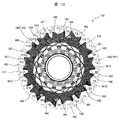
- FIG. 10 is a view of the armature of the DC motor in the comparative example as viewed from the commutator side.
- the armature coil (coil) Wn, the armature slot Sn, and the commutator piece Cn are particularly required to specify the position of the armature coil (coil), the armature slot, and the commutator piece.
- n 1, 2, 3,... 13
- armature coil (coil) 106, armature slot 171, commutator piece 182 and the like Describe.
- the coil W5 and the coil W6, the coil W7 and the coil W8, the coil W9 and the coil W10, the coil W11 and the coil W12 are wound in the same manner, and finally the coil W13 is wound.
- the coil is wound while being hooked on the commutator piece formed in a hook shape with a single stroke, and finally the commutator piece No. Winding ends at C1.
- the double connecting part 162 in which the winding conductor is two on the commutator piece is the commutator piece no. With only C1, the other commutator piece is a single connection portion 161 having one winding conductor. In addition, since the coils are continuously wound via the coil connecting wire 188, the winding time is required for the winding process for 13 coils.
- the number is 7 at the end of winding.
- a point (part) where these seven coil connecting wires 188 cross the outer surface of the coil is indicated by a dotted circle 183.
- a portion 183 where the coil connecting wire 188 crosses the outer surface of the coil is a portion where the plurality of coils 106 are stacked and becomes the highest among the coil end portions 106a, and is exposed to the upper side of the stacked coils 106. This is a location that crosses the portion 106a.
- the commutator piece No. The coil connection line 188 connected to C4 crosses over the portion where the coil W5 and the coil W3 are laminated. At this time, in the vicinity of the laminated part of the coil W5 and the coil W3, the coil W1 has entered under the laminated part of the coil W5 and the coil W3. For this reason, the commutator piece No.
- the coil connection line 188 connected to C4 substantially crosses over the portion where the three coils 106 of the coil W5, the coil W3, and the coil W1 are laminated.
- the thickness (height) dimension of the portion where these three coils are laminated is the largest thickness (height) dimension in the coil end 106a.
- the positions of the coil connection wires 188 are slightly changed because they are not restrained by the coil 106. It is possible to vibrate. If these coil connection wires 188 come into contact with other components or are rubbed against the coil 106 by vibration, disconnection or insulation failure may occur. Motors mounted on automobiles must have a strong structure against vibrations. If the coil end portion 106a is increased in order to increase the reliability, the volume of the motor is increased, and the mountability to the automobile is deteriorated. According to the winding method for a DC motor according to the present invention, the number of coil connection wires crossing the outer surface of the coil can be reduced, and a DC motor excellent in miniaturization (mountability) and reliability can be provided.
- FIG. 1 is a cross-sectional view of a DC motor according to the present embodiment as viewed from the side.
- FIG. 2 is a diagram showing one coil group composed of two coils according to the present embodiment and the state of winding around the armature slot.
- FIG. 3 is an explanatory diagram of the winding situation in the present embodiment.
- FIG. 4 is an external view showing a winding state around the armature in the present embodiment.
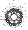
- FIG. 5 is a diagram of the armature of the DC motor according to the present embodiment as viewed from the commutator side.
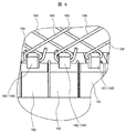
- FIG. 6 is an enlarged view showing a state where the coil connection line is locked to the conductor locking portion.
- the DC motor according to the present invention is particularly suitable for use as a motor used as a drive source for automobile electrical equipment, for example, a motor used for engine valve control or a hydraulic pump drive motor.
- the DC motor 200 includes a yoke 104, a front bracket 103, a field magnet 105, and an armature 101 (rotor).
- the yoke 104 has a substantially cylindrical shape with a bottom, and includes a rear bearing 121 and a brush holder 130.
- the rear bearing 121 is disposed at the center of the end face of the yoke 104 and rotatably supports one end of the shaft 110.
- the front bracket 103 has a substantially disk shape and includes a front bearing 120.
- the front bracket 103 is disposed at the end of the yoke 104.
- the brush holder 130 holds the brush 115.
- the brush 115 is urged toward the commutator 102 by a brush pressurizing spring 131 so that energization by mechanical sliding contact with the commutator 102 can stably supply power even during rotation.
- a current accompanying a rectifying action flows through the armature coil 106, a continuous rotational torque is generated by the interaction between the magnetic field generated by the field magnet 105 and the magnetic field generated by the armature 101, and a mechanical output is obtained.
- the armature coil 106 may be simply referred to as a coil.
- FIG. 2 shows one coil group consisting of two coils (number of pole pairs P: 2) in which the coils are electrically connected to the commutator piece by the same continuous line as the winding conductor, and the winding to the armature slot 171. Indicates the status of the clothing.
- such a winding method or a wound state is referred to as two-continuous winding.
- the number of turns 2 means that the armature slot makes two turns, and for each armature slot in which the winding conductor is separated per coil, two forwards and two return lines are accommodated. That means.
- the winding of the coil group composed of two coils starts winding from the coil end winding start portion 185 locked to the conductor locking portion 184, and is wound a predetermined number of turns as the first coil, A coil end winding end portion that is wound a predetermined number of turns as the second coil via the inter-coil hairpin portion 186 locked to the conductor locking portion 184 and locked to the conductor locking portion 184 The process ends at 187.
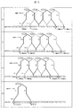
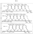
- FIG. 3 shows a winding situation according to the first embodiment.
- (a) is a 1st layer
- (b) is a 2nd layer
- (c) is a 3rd layer
- (d) has shown the winding condition about the 4th layer.
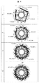
- FIG. 4 shows the appearance of the armature corresponding to each winding situation of FIGS. 3 (a) to 3 (d).
- Ns is the number of slots
- P is the number of pole pairs.
- These coil groups 181 are composed of coils 106.
- the number of coils is thirteen.
- the coil group (1) -1 is composed of a coil W1 and a coil W2
- the coil group (1) -2 is composed of a coil W3 and a coil W4
- the coil group (2) -1 is composed of a coil W5.
- the coil group (2) -2 is composed of a coil W7 and a coil W8,
- the coil group (3) -1 is composed of a coil W9 and a coil W10
- the coil group (3) -2 is composed of a coil W11.
- the coil group (4) -1 is composed of the coil W13.
- FIG. 3 shows the winding state in a simplified manner, where the coil 106 is wound once in each armature slot 171 (S1 to S13), and the coil 106 is placed in each armature slot 171. On the other hand, the situation where it is wound a plurality of times is not shown. Further, numbers are assigned to the coils and the coil groups according to the winding order.
- the winding order is the order of the coils W1, W2,..., The coil W13 for the coils, and the coil group (1) for the coil groups. -1, coil group (1) -2, coil group (2) -1,... Coil group (4) -1.
- (a) shows a winding connection diagram of the coil group (1) -1 and the coil group (1) -2 constituting the first layer, and an armature after the first layer winding.
- (B) shows the winding connection diagram of the coil group (2) -1 and coil group (2) -2 constituting the second layer, and the outer appearance of the armature after the second layer winding.
- (C) shows the winding connection diagram of the coil group (3) -1 and the coil group (3) -2 constituting the third layer and the appearance of the armature after the third layer winding.
- (D) shows the winding connection diagram of the coil group (4) -1 constituting the fourth layer and the appearance of the armature after the fourth layer winding.
- Coil group (1) -1 is commutator piece no. Winding starts from C1.
- the coil end winding start portion 185 of the coil W1 which is a constituent element of the coil group (1) -1, is connected to the commutator piece No. Hook it on C1 and armature slot no. From S1, armature slot no.
- the coil W1 is wound over S4.
- the hairpin part between the coils is connected to the commutator piece No. Hook it on C7 and set armature slot no. From S7, armature slot no.
- the coil W2 is wound over S10.
- the coil end winding end portion 187 is connected to the commutator piece No.
- the coil group (1) -1 is wound by hooking on C13.
- the coil W1 and the coil W2 of the coil group (1) -1 are continuously wound without being cut in the middle of one winding conductor.
- the coil group (1) -1 is composed of a coil W1 and a coil W2 wound by two continuous windings with one winding conductor.
- Coil group (1) -2 has commutator piece no. Winding starts from C4.
- the coil end winding start portion 185 of the coil W3, which is a component of the coil group (1) -2, is connected to the commutator piece No. Hook it on C4, armature slot no. From S4, armature slot no.
- the coil W3 is wound over S7.
- the hairpin part between the coils is connected to the commutator piece No. Hook it on C10, and armature slot no. From S10, armature slot no.
- the coil W4 is wound over S13.
- the coil end winding end portion 187 is connected to the commutator piece No.
- the coil group (1) -2 is wound by being hooked on C3.
- the coil W3 and the coil W4 of the coil group (1) -2 are wound continuously without being cut in the middle of one winding conductor.
- the coil group (1) -2 is composed of a coil W3 and a coil W4 wound by two continuous windings with one winding conductor.
- Armature slot No. S4, No. S7, No. In S10 different coils are distributed so that the coils in the first layer do not overlap as shown in FIG. Can be wound.
- the first to fourth electric machines are wound by the first layer on the lowermost layer without overlapping on the armature coil 106 wound between different armature slots, and are sequentially arranged adjacent to each other.
- the child coils 106 (W1 to W4) are configured.
- the first to fourth armature coils 106 (W1 to W4) are accommodated in the same armature slot 171 (S4, S7, S10) with the coil sides adjacent to each other.
- Coil group (2) -1 has commutator piece no. Winding starts from C13.
- the coil end winding start portion 185 of the coil W5, which is a component of the coil group (2) -1, is connected to the commutator piece No. Hook it on C13 and set armature slot no. From S13, armature slot no.
- the coil W5 is wound over S3.
- the hairpin part between the coils is connected to the commutator piece No. Hook it on C6, armature slot no. From S6, armature slot no.
- the coil W6 is wound over S9.
- the coil end winding end portion 187 is connected to the commutator piece No.
- the coil group (2) -1 is wound by hooking on C12.
- the coil W5 and the coil W6 of the coil group (2) -1 are continuously wound without cutting one winding conductor in the middle.
- the coil group (2) -1 is composed of a coil W5 and a coil W6 wound by two continuous windings with one winding conductor.
- Coil group (2) -2 has commutator piece no. Winding starts from C3.
- the coil end winding start portion 185 of the coil W7 which is a constituent element of the coil group (2) -2, is connected to the commutator piece No. Hook it on C3, and armature slot no. From S3, armature slot no.
- the coil W7 is wound over S6.
- the hairpin part between the coils is connected to the commutator piece No. Hook it on C9, armature slot no. From S9, armature slot no.
- the coil W8 is wound over S12.
- the coil end winding end portion 187 is connected to the commutator piece No. It is hooked on C2 and the winding of the coil group (1) -2 is completed.
- the coil W7 and the coil W8 of the coil group (2) -2 are wound continuously without being cut in the middle of one winding conductor.
- the coil group (2) -2 is composed of a coil W7 and a coil W8 wound by two continuous windings with one winding conductor.
- the second layer is wound at the same slot pitch 3 as the first to fourth armature coils W1 to W4 on the armature coils W1 to W4 wound on the lowermost layer (first layer).
- a plurality of armature coils W5 to W8 are formed.
- Coil group (3) -1 is commutator piece no. Winding starts from C12.
- the coil end winding start portion 185 of the coil W9 which is a component of the coil group (3) -1, is connected to the commutator piece No. Hook it on C12, and armature slot no. From S12, armature slot no.
- the coil W9 is wound over S2.
- the hairpin part between the coils is connected to the commutator piece No. Hook it on C5 and set the armature slot no. From S5, armature slot no.
- the coil W10 is wound over S8.
- the coil end winding end portion 187 is connected to the commutator piece No. It is hooked on C11 and the winding of the coil group (3) -1 is finished.
- the coil W9 and the coil W10 of the coil group (3) -1 are continuously wound without being cut in the middle of one winding conductor.
- the coil group (3) -1 is composed of a coil W9 and a coil W10 wound by two continuous windings with one winding conductor.
- Coil group (3) -2 has commutator piece no. Winding starts from C2.
- the coil end winding start portion 185 of the coil W11 which is a component of the coil group (3) -2 is connected to the commutator piece No.
- the armature slot no. From S2, armature slot no.
- the coil W11 is wound over S5.
- the hairpin part between the coils is connected to the commutator piece No. Hook it on C8 and set armature slot no. From S8, armature slot no.
- the coil W12 is wound over S11.
- the coil end winding end portion 187 is connected to the commutator piece No. It is hooked on C1 and the winding of the coil group (3) -2 is completed.
- the coil W11 and the coil W12 of the coil group (3) -2 are wound continuously without being cut in the middle of one winding conductor.
- the coil group (3) -1 is composed of a coil W11 and a coil W12 wound by two continuous windings with one winding conductor.
- the third layer is wound on the armature coils W5 to W8 wound on the lower layer (second layer) at the same slot pitch 3 as the first to fourth armature coils W1 to W4.
- a plurality of armature coils W5 to W8 are configured.
- Coil group (4) -1 is commutator piece no. Winding starts from C11.
- the coil end winding start portion 185 of the coil W13 which is a component of the coil group (4) -1, is connected to the commutator piece No. Hang on the armature slot No. From S11, armature slot no.
- the coil W13 is wound over S1.
- the coil end winding end portion 187 is connected to the commutator piece No. It is hooked on C4 and the winding of the coil group (4) -1 is completed.
- the conductor engaging portion 184 is welded to establish electrical connection between the coil 106 and the commutator piece 182, and this is used as the armature 101.
- the lowermost layer of the coil end portion 106a is composed of two coil groups (1) -1 and (1) -2.
- the armature coils 106 of one coil group and the armature coils 106 of the other coil group are alternately arranged in the circumferential direction so that the four armature coils 106 included in the two coil groups do not overlap each other. It is wound.
- the coil groups (2) -1, (2) -2, (3) -1 and (3) -2 are wound on the upper layer of the coil groups (1) -1 and (1) -2 constituting the lowermost layer.
- the intermediate layer armature coil 106 is formed.
- the intermediate layer is composed of two coil groups. In the intermediate layer, focusing on one layer, the four armature coils 106 included in the two coil groups are wound at the same slot pitch and coil interval as the four armature coils 106 arranged in the lowermost layer. Yes.
- the coil interval is set such that the four coils 106 do not overlap each other.
- the winding order of the coil groups (1) -1 and (1) -2 may be switched. The same applies to (2) -1 and (2) -2, (3) -1 and (3) -2.
- the gist of the present invention is not to specify the order of winding, and it is only necessary to establish the circumferential position of the coil and the coil group and the commutator piece. It is to eliminate the overlap.
- FIG. 5 is an explanatory diagram of windings as viewed from the commutator 102 side of the armature 101 of the DC motor 200 according to the present embodiment.
- the location where the coil connecting wire 188 crosses the outer surface of the coil is the armature slot No. of the coil 13 of the coil group (4) -1.
- Only the coil connection line 188 connected to the commutator piece No. C4 from S1 (the part 183 surrounded by a dotted circle).
- the coil connection wire 188 is effectively damaged without causing damage.
- the end can be made smaller.
- armature coil 106 is divided into a plurality of coil groups and each is wound while being connected to the conductor engaging portion 184 of the commutator piece 182, a double hook (two coil connection wires 188, conductor connection) There are a plurality of connecting portions) that are hooked on the stopper 184.
- one region (circumferential range of the commutator) where the double hooks exist together and a conductor locking portion where the middle portion of the two coils included in one coil group is locked.
- One region (a range in the circumferential direction of the commutator) in which 184 (single hook) is present together is formed. That is, the single hook and the double hook are divided into two regions and aligned.
- the number of winding conductors is different between the single connection portion 161 and the double connection portion 162 as a fusing treatment condition for electrical connection between the coil 106 and the commutator piece 182, a welding machine is used to stabilize the connection state. It is preferable to perform the fusing process while appropriately adjusting the voltage and the welding process time of the single connection part 161 and the double connection part 162.
- the coil winding conductor is normally wound while supplying a continuous conductor from the winding bobbin.
- a switching operation between the coil group and the coil group such as winding of the coil group-cutting of the winding conductor-winding of the coil group.
- the winding conductor may be cut by a tearing operation using the hook shape of the conductor locking portion 184, or a dedicated cutter may be used, and an appropriate method may be selected.
- FIG. 6 shows an enlarged view of the coil connection line 188 and the conductor locking portion 184.
- the conductor locking portion 184 of the commutator piece 182 located at the center and the left side of the drawing is a double connection portion 162
- the conductor locking portion 184 of the commutator piece 182 located at the right side is a single connection portion 161.
- the coil connection wire 188 is hooked on the hook-shaped conductor locking portion 184 in an ⁇ shape, plastically processed from the hook shape to the inner diameter side of the commutator, and then subjected to a welding process to perform the coil connection wire 188 and the commutator.
- the piece 182 is electrically connected.
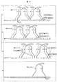
- FIG. 7 is an explanatory diagram of the winding state of the fourth layer according to the present embodiment.
- the coil connection wire 188 is a winding method that can improve this against crossing the outer surface of the coil at one place. Only the coil 13 (coil group (4) -1) will be described, and the windings of the other coil groups are the same as those in the first embodiment, and thus the description thereof is omitted. As shown in FIG. 7, the coil end winding start portion 185 of the coil 13 which is a component of the coil group (4) -1 is connected to the commutator piece No. Hang on the armature slot No. From S11, armature slot no. The coil 13 is wound over S1, only the final winding conductor of the coil 13 is turned around to the armature slot No.
- FIG. 8 shows the winding state of the advanced winding (closed winding) of the 6-pole 17-slot wave winding according to this embodiment.
- Ns is the number of slots
- P is the number of pole pairs.
- a coil is wound on the basis of a triple winding, and a double winding is adopted for a part.
- the triple winding is applied to a coil group constituting each layer from the lowermost layer to the uppermost layer, and a part of the coil group is wound in a triple winding on the uppermost layer.
- the double winding is applied to a part of the coil group constituting the uppermost layer.
- the number of coils is 17, the coil group (1) -1 is composed of a coil W1, a coil W2, and a coil W3, and the coil group (1) -2 is composed of a coil W4, a coil W5, and a coil W6.
- (2) -1 is composed of coil W7, coil W8 and coil W9
- coil group (2) -2 is composed of coil W10, coil W11 and coil W12
- coil group (3) -1 is composed of coil W13 and coil W12. W14 and coil W15
- coil group (3) -2 is composed of coils W16 and W17.
- FIG. 8 shows the winding state in a simplified manner.
- the coil 106 shows a state where the coil 106 is wound once in each armature slot 171 (S1 to S17), and the coil 106 is placed in each armature slot 171. On the other hand, the situation where it is wound a plurality of times is not shown. Further, numbers are assigned to the coils and the coil groups according to the winding order.
- the winding order is the coil W1, the coil W2,..., The coil W17 for the coil, and the coil group (1) -1, Winding is performed in the order of coil group (1) -2, coil group (2) -1,..., Coil group (3) -2.
- FIG. 8 shows a winding connection diagram of the coil group (1) -1 and the coil group (1) -2 constituting the first layer, and (b) shows the second layer.
- a winding connection diagram of the coil group (2) -1 and the coil group (2) -2 is shown, and (c) shows the coil group (3) -1 and the coil group (3) -2 constituting the third layer.
- the winding connection diagram is shown.
- Coil group (1) -1 has commutator piece no. Winding starts from C1.
- the coil end winding start portion 185 of the coil W1 which is a constituent element of the coil group (1) -1, is connected to the commutator piece No. Hook it on C1 and armature slot no. From S1, armature slot no.
- the coil W1 is wound over S4.
- the hairpin part between the coils is connected to the commutator piece No. Hook it on C7 and set armature slot no. From S7, armature slot no.
- the coil W2 is wound over S10.
- the hairpin part between the coils is connected to the commutator piece No. Hook it on C13 and set armature slot no. From S13, armature slot no.
- the coil W3 is wound over S16.
- the coil end winding end portion 187 is connected to the commutator piece No.
- the coil group (1) -1 is completely wound by hooking on C2.
- one winding conductor is continuously wound without being cut halfway.
- the coil group (1) -1 is composed of coils W1 to W3 wound by three continuous windings with one winding conductor.
- Coil group (1) -2 has commutator piece no. Winding starts from 4.
- the coil end winding start portion 185 of the coil W4, which is a component of the coil group (1) -2, is connected to the commutator piece No. Hook it on C4, armature slot no. From S4, armature slot no.
- the coil C4 is wound over S7.
- the hairpin part between the coils is connected to the commutator piece No. Hook it on C10, and armature slot no. From S10, armature slot no.
- the coil W5 is wound over S13.
- the hairpin part between the coils is connected to the commutator piece No. Hang on the armature slot No. From S16, armature slot no.
- the coil W6 is wound over S2.
- the coil end winding end portion 187 is connected to the commutator piece No. It is hooked on C5 and the winding of the coil group (1) -2 is finished.
- the coils W4 to W6 of the coil group (1) -1 one winding conductor is continuously wound without being cut halfway.
- the coil group (1) -1 is composed of coils W4 to W6 wound by three continuous windings with one winding conductor.
- different coils share the slots in which the coil sides are accommodated so that the coils W1 to W5 of the coils W1 to W6 constituting the first layer are distributed so that the coils do not overlap each other.
- Coil W6 is wound on top of coil W1 wound earlier. That is, the coils W1 to W5 constituting the first layer are wound on the lowermost layer without overlapping on the armature coil 106 wound between the different armature slots, and are sequentially arranged adjacent to each other.
- First to fifth armature coils 106 (W1 to W5) are configured.
- the first to fifth armature coils 106 (W1 to W5) are accommodated in the same armature slot 171 (S4, S7, S10, S13, S16) with the coil sides adjacent to each other.
- Coil group (2) -1 has commutator piece no. Winding starts from C17.
- the coil end winding start portion 185 of the coil W7 which is a component of the coil group (2) -1, is connected to the commutator piece No. Hook it on C17 and armature slot no. From S17, armature slot no.
- the coil W7 is wound over S3.
- the hairpin part between the coils is connected to the commutator piece No. Hook it on C6, armature slot no. From S6, armature slot no.
- the coil W8 is wound over S9.
- the hairpin part between the coils is connected to the commutator piece No. Hook it on C12, and armature slot no. From S12, armature slot no.
- the coil W9 is wound over S15.
- the coil end winding end portion 187 is connected to the commutator piece No.
- the coil group (2) -1 is wound by being hooked on C1.
- one winding conductor is continuously wound without being cut halfway.
- the coil group (2) -1 is constituted by coils W7 to W9 wound by three continuous windings with one winding conductor.
- Coil group (2) -2 has commutator piece no. Winding starts from C3.
- the coil end winding start portion 185 of the coil W10 which is a component of the coil group (2) -2, is connected to the commutator piece No. Hook it on C3, and armature slot no. From S3, armature slot no.
- the coil W10 is wound over S6.
- the hairpin part between the coils is connected to the commutator piece No. Hook it on C9, armature slot no. From S9, armature slot no.
- the coil W11 is wound over S12.
- the hairpin part between the coils is connected to the commutator piece No. Hook it on C15, armature slot no. From S15, armature slot no.
- the coil W12 is wound over S1.
- the coil end winding end portion 187 is connected to the commutator piece No.
- the coil group (2) -2 is wound by hooking on C4.
- one winding conductor is continuously wound without being cut halfway.
- the coil group (2) -2 is composed of coils W10 to W12 wound by three continuous windings with one winding conductor.
- the second layer is wound on the armature coils W1 to W6 wound on the lower layer (first layer) at the same slot pitch 3 as the first to sixth armature coils W1 to W6.
- a plurality of armature coils W7 to W12 are configured.
- Coil group (3) -1 has commutator piece no. Winding starts from C2.
- the coil end winding start portion 185 of the coil W13 which is a constituent element of the coil group (3) -1 is connected to the commutator piece No.
- the coil W13 is wound over S5.
- the hairpin part between the coils is connected to the commutator piece No. Hook it on C8 and set armature slot no. From S8, armature slot no.
- the coil W14 is wound over S11.
- the hairpin part between the coils is connected to the commutator piece No.
- the armature slot no From S14, armature slot no.
- the coil W15 is wound over S17.
- the coil end winding end portion 187 is connected to the commutator piece No. It is hooked on C3 and the winding of the coil group (3) -1 is finished.
- the coils W13 to W15 of the coil group (3) -1 are wound continuously without being cut in the middle of one winding conductor.
- the coil group (3) -1 is constituted by coils W13 to W15 wound by three continuous windings with one winding conductor.
- Coil group (3) -2 has commutator piece no. Winding starts from C5.
- the coil end winding start portion 185 of the coil W16 which is a constituent element of the coil group (3) -2, is connected to the commutator piece No. Hook it on C5 and set the armature slot no. From S5, armature slot no.
- the coil W16 is wound over S8.
- the hairpin part between the coils is connected to the commutator piece No. Hang on the armature slot No. From S11, armature slot no.
- the coil W17 is wound over S14.
- the coil end winding end portion 187 is connected to the commutator piece No. It is hooked on C17 and the winding of the coil group (3) -2 is completed.
- the coils W16 and W17 of the coil group (3) -2 are continuously wound without cutting one winding conductor in the middle.
- the coil group (3) -1 is composed of coils W16 and W17 wound by two continuous windings with one winding conductor.
- the third layer is wound on the armature coils W7 to W12 wound on the lower layer (second layer) at the same slot pitch 3 as the first to sixth armature coils W1 to W6.
- a plurality of armature coils W13 to W17 are configured.
- the commutator piece that is a double hook to which two independent coil connection lines are connected is No. There are 6 locations in total, C1 to C5 and C17. There are a total of 11 locations from C6 to C16.
- one region where the double hooks exist together (circumferential range of the commutator) and one region where the single hooks exist together (circumferential range of the commutator) are formed. The That is, the single hook and the double hook are divided into two regions and aligned.
- the conductor engaging portion 184 is welded to establish electrical connection between the coil 106 and the commutator piece 182, and this is used as the armature 101.
- the lowermost layer of the coil end portion 106a is composed of two coil groups (1) -1 and (1) -2.
- the armature coils 106 of one coil group and the armature coils 106 of the other coil group are alternately arranged in the circumferential direction so that the six armature coils 106 included in the two coil groups do not overlap each other. It is wound.
- Coil groups (2) -1 and (2) -2 are wound on the upper layer of coil groups (1) -1 and (1) -2 constituting the lowermost layer, and constitute armature coil 106 of the intermediate layer .
- the intermediate layer is composed of two coil groups. In the intermediate layer, focusing on one layer, the six armature coils 106 included in the two coil groups are wound at the same slot pitch and coil interval as the six armature coils 106 arranged in the lowermost layer. Yes.
- the coil interval is set such that the six coils 106 do not overlap each other.
- Example 1 Example 2, and Example 3
- the coil 106 was wound for every layer so that the coil does not overlap at the coil end portion 106a, or the portion where the coil overlaps was made one place. It is not always necessary to eliminate all the layers of the coil overlap part. By eliminating the coil overlap part for at least one layer, the coil end part overlap can be simplified. The effect which suppresses collapse of a coil at the time of winding can be show
- the present invention is preferably applied to a motor having four or more field magnetic poles (two or more pole pairs).
- two coils 106 are wound around a single tooth, and are sandwiched and wound between these two coils 106 wound around the hook.
- a coil 106 is present.
- the coils W5, W7, W6, W8, and W9 in the portions of the teeth T1, T4, T7, T10, and T13 correspond to the coil 106 that is sandwiched and wound between two coils 106.
- coils W3, W10, W8, W6, W4, W11, W9, W7, and W5 in the portions of teeth T1, T4, T5, T6, T7, T10, T11, T12, and T13 are two coils 106. It corresponds to the coil 106 sandwiched between and wound.
- the coil 106 Since such a coil 106 is wound on the lower layer coil 106 and receives a force from the coil 106 wound on the upper layer while applying tension, the coil 106 is likely to collapse. In FIG. 5, there are nine places where such winding collapse is likely to occur, whereas in FIG. 10, there are nine places. Therefore, according to each of the above-described embodiments, the coil 106 can be wound by reducing the number of places where the coil is easily collapsed. Therefore, the coil end is less likely to be collapsed, which is advantageous for making the coil end portion 106a compact.
- the DC motor having the armature coil 106 wound by the wave winding method is not limited to the above-described number of poles / slots, and the embodiment of the present invention can be applied to achieve the effect. .
- the winding method as shown in FIG. 10 is called wave winding.
- the winding method of each embodiment according to the present invention is precisely different from wave winding.
- the winding method of each embodiment is a winding method for realizing a winding form that operates in the same manner as a winding form generally called a wave winding, and is similar to a wave winding. I'm calling.
- the number of overlapping coils of the coil end portion 106a of the armature coil can be reduced, the coil end height can be set low, and the motor can be miniaturized.
- the coil connecting wire is arranged inside the coil, and there is an effect that a contact with other components and vibration can be suppressed and a highly reliable motor can be obtained.
- the coil end portion can be made compact by reducing the number of coil connecting wires that cross the outer surface of the coil end portion. And miniaturization as a motor for automobile electrical equipment can be achieved, and its mountability can be improved. Furthermore, it is possible to reduce the possibility that the coil connection line is rubbed with other components due to contact or vibration, and it is possible to prevent disconnection or insulation failure of the coil connection line and to ensure high reliability.
- this invention is not limited to each above-mentioned Example, Various modifications are included.
- the above-described embodiments have been described in detail for easy understanding of the present invention, and are not necessarily limited to those having all the configurations.
- a part of the configuration of one embodiment can be replaced with the configuration of another embodiment, and the configuration of another embodiment can be added to the configuration of one embodiment.
Landscapes
- Engineering & Computer Science (AREA)
- Power Engineering (AREA)
- Windings For Motors And Generators (AREA)
- Dc Machiner (AREA)
Abstract
Description
アーマチャアコアは4極13スロットの構成であり、アーマチャアコイルは波巻で巻線されている。具体的には、一つのコイルは、2つのスロットを間に挟んで、その周方向両側に配置された略T字型磁極部に跨って巻回されている。すなわち、一つのコイルは、任意のスロット(第1のスロット)と、この第1のスロットから2つのスロットを飛び越した先にある第2のスロットとに跨って巻装されている。アーマチャアコイルの数は13であり、各アーマチャアコイルC1~C13と巻装されるスロットS1~S13との関係は以下の通りである。第1のアーマチャアコイルC1はスロットS1とS4とに、第2のアーマチャアコイルC2はスロットS7とS10とに、第3のアーマチャアコイルC3はスロットS13とS3とに、第4のアーマチャアコイルC4はスロットS6とS9とに、第5のアーマチャアコイルC5はスロットS12とS2とに、第6のアーマチャアコイルC6はスロットS5とS8とに、第7のアーマチャアコイルC7はスロットS11とS1とに、第8のアーマチャアコイルC8はスロットS4とS7とに、第9のアーマチャアコイルC9はスロットS10とS13とに、第10のアーマチャアコイルC10はスロットS3とS6とに、第11のアーマチャアコイルC11はスロットS9とS12とに、第12のアーマチャアコイルC12はスロットS2とS5とに、第13のアーマチャアコイルC13はスロットS8とS11とに、それぞれ跨って巻装されている。
なお、図8は巻装状況を簡略化して示しており、コイル106は各電機子スロット171(S1~S17)に1回巻回した状況を示しており、コイル106を各電機子スロット171に対して複数回巻回した状況については図示していない。また、巻装順序に応じ、番号をコイルおよびコイル群に付けており、巻装順序は、コイルについてはコイルW1,コイルW2,…,コイルW17、コイル群についてはコイル群(1)-1,コイル群(1)-2,コイル群(2)-1,…,コイル群(3)-2の順序で巻装を行っていく。
Claims (9)
- 複数の電機子スロットと、一定数の電機子スロットを挟んで離間する2つの電機子スロットに跨って巻装された電機子コイルとを有する電機子を備えた直流モータにおいて、
コイルエンド部の最下層に、他の電機子スロットに巻装された電機子コイル上に重なることなく巻装された少なくとも4つの電機子コイルを備え、
最下層に巻装された前記4つの電機子コイルの上層に、前記4つの電機子コイルと同じ様式で巻装された少なくとも4つの電機子コイルを備えたことを特徴とする直流モータ。 - 請求項1に記載の直流モータにおいて、
最下層に巻装された前記4つの電機子コイルは、隣り合うコイル辺同士がそれぞれ同じ電機子スロットに収容され、最下層の上層に巻装された前記4つの電機子コイルは、隣り合うコイル辺同士がそれぞれ同じ電機子スロットに収容されたことを特徴とする直流モータ。 - 請求項2に記載の直流モータにおいて、
前記電機子コイルは、一本の連続した巻線導体で巻回された極対数Pに等しい個数のコイルからなる複数のコイル群と、(P-1)個のコイルからなるコイル群とを構成し、
一本の連続した巻線導体で巻回された二つのコイル間が連続した状態のまま整流子片の導体係止部に係止されており、
各コイル群の両端部が前記整流子片とは異なる整流子片の導体係止部に係止された状態で切断されていることを特徴とする直流モータ。 - 請求項3に記載の直流モータにおいて、
P個のコイルからなるコイル群の数は、スロット数Nsを極対数Pで除した値の小数第1位以下を切り捨てた自然数と一致し、(P-1)個のコイルからなるコイル群は1個であることを特徴とする直流モータ。 - 請求項4に記載の直流モータにおいて、
整流子は、各コイル群の両端部が係止されることにより独立した2本の巻線導体が係止された複数の導体係止部と、一本の連続した巻線導体で巻回された二つのコイル間が連続した状態のまま係止されることにより1本の巻線導体が係止された複数の導体係止部とを備え、
2本の巻線導体が係止された複数の導体係止部と1本の巻線導体が係止された複数の導体係止部とは、前記整流子の周方向における2つの領域に分かれて整列していることを特徴とする直流モータ。 - 請求項5に記載の直流モータにおいて、
界磁磁極数が4以上であることを特徴とする直流モータ。 - 請求項6に記載の直流モータにおいて、
前記コイル群が4個以上であることを特徴とする直流モータ。 - 請求項5に記載の直流モータにおいて、
界磁磁極数が4であり、スロット数が13であることを特徴とする直流モータ。 - 請求項5に記載の直流モータにおいて、
前記コイル群が4個以上であり、界磁磁極数が6であり、スロット数が17であることを特徴とする直流モータ。
Priority Applications (3)
| Application Number | Priority Date | Filing Date | Title |
|---|---|---|---|
| CN201580008890.3A CN106030992B (zh) | 2014-02-17 | 2015-01-14 | 直流马达 |
| JP2015562762A JP6258978B2 (ja) | 2014-02-17 | 2015-01-14 | 直流モータ |
| US15/117,335 US10170954B2 (en) | 2014-02-17 | 2015-01-14 | Direct current motor |
Applications Claiming Priority (2)
| Application Number | Priority Date | Filing Date | Title |
|---|---|---|---|
| JP2014-027190 | 2014-02-17 | ||
| JP2014027190 | 2014-02-17 |
Publications (1)
| Publication Number | Publication Date |
|---|---|
| WO2015122226A1 true WO2015122226A1 (ja) | 2015-08-20 |
Family
ID=53799974
Family Applications (1)
| Application Number | Title | Priority Date | Filing Date |
|---|---|---|---|
| PCT/JP2015/050705 Ceased WO2015122226A1 (ja) | 2014-02-17 | 2015-01-14 | 直流モータ |
Country Status (4)
| Country | Link |
|---|---|
| US (1) | US10170954B2 (ja) |
| JP (1) | JP6258978B2 (ja) |
| CN (1) | CN106030992B (ja) |
| WO (1) | WO2015122226A1 (ja) |
Families Citing this family (9)
| Publication number | Priority date | Publication date | Assignee | Title |
|---|---|---|---|---|
| KR102233309B1 (ko) * | 2014-04-28 | 2021-03-29 | 삼성전자주식회사 | 모터 및 모터의 제조방법 |
| FR3090236B1 (fr) * | 2018-12-14 | 2021-01-15 | Valeo Equip Electr Moteur | Moteur électrique, pour démarreur, comprenant un rotor à épingles et un collecteur |
| FR3090235A1 (fr) * | 2018-12-14 | 2020-06-19 | Valeo Equipements Electriques Moteur | Moteur électrique, pour démarreur, comprenant un rotor à épingles et un collecteur |
| US11427344B2 (en) | 2019-03-01 | 2022-08-30 | Pratt & Whitney Canada Corp. | Cooling system configurations for an aircraft having hybrid-electric propulsion system |
| US11628942B2 (en) | 2019-03-01 | 2023-04-18 | Pratt & Whitney Canada Corp. | Torque ripple control for an aircraft power train |
| WO2020219112A1 (en) | 2019-04-25 | 2020-10-29 | United Technologies Advanced Projects, Inc. | Aircraft degraded operation ceiling increase using electric power boost |
| US11667391B2 (en) | 2019-08-26 | 2023-06-06 | Pratt & Whitney Canada Corp. | Dual engine hybrid-electric aircraft |
| US12535014B2 (en) | 2019-09-06 | 2026-01-27 | Hamilton Sundstrand Corporation | Vortex turbines for a hybrid-electric aircraft |
| US11738881B2 (en) | 2019-10-21 | 2023-08-29 | Hamilton Sundstrand Corporation | Auxiliary power unit systems |
Citations (3)
| Publication number | Priority date | Publication date | Assignee | Title |
|---|---|---|---|---|
| JPS61231853A (ja) * | 1985-04-08 | 1986-10-16 | Igarashi Denki Seisakusho:Kk | 無整流子直流モ−タコイルの巻線方法と無整流子直流モ−タ |
| JPH0614486A (ja) * | 1992-05-08 | 1994-01-21 | Ind Magneti Marelli Spa | 電気モータ特にブラシレスモータに対する始動巻き線を製作する方法および装置 |
| JP2009213258A (ja) * | 2008-03-04 | 2009-09-17 | Mitsuba Corp | 電動モータ |
Family Cites Families (11)
| Publication number | Priority date | Publication date | Assignee | Title |
|---|---|---|---|---|
| US3913220A (en) * | 1968-02-09 | 1975-10-21 | Globe Tool Eng Co | Armature winding method |
| US3705459A (en) * | 1971-06-24 | 1972-12-12 | Globe Tool Eng Co | Wave winding of armatures |
| US3818257A (en) * | 1972-04-14 | 1974-06-18 | Ametek Inc | Rotary armature for a rotary dynamoelectric machine |
| DE2744222C2 (de) * | 1977-09-30 | 1984-10-18 | Siemens AG, 1000 Berlin und 8000 München | Wicklungsanordnung für einen elektrischen Zweimotorenantrieb |
| DE2744472C2 (de) * | 1977-10-03 | 1983-11-03 | Siemens AG, 1000 Berlin und 8000 München | Elektrischer Zweimotorenantrieb |
| US4329610A (en) * | 1980-04-14 | 1982-05-11 | Black & Decker Inc. | Armature winding pattern for an electric motor |
| US4417388A (en) * | 1980-11-28 | 1983-11-29 | Allied Corporation | Method of making a multiple open turn lap wound dynamoelectric machine |
| JPS60103270U (ja) * | 1983-12-20 | 1985-07-13 | 株式会社 三ツ葉電機製作所 | 直流機 |
| US4616788A (en) * | 1985-02-05 | 1986-10-14 | The Globe Tool & Engineering Co. | Method and apparatus for winding dynamoelectric devices |
| JPH10285854A (ja) | 1997-03-31 | 1998-10-23 | Sawafuji Electric Co Ltd | 直流モータ回転子及びその巻線方法 |
| JP4025250B2 (ja) * | 2003-06-17 | 2007-12-19 | ヤマハモーターエレクトロニクス株式会社 | 直流電動機 |
-
2015
- 2015-01-14 WO PCT/JP2015/050705 patent/WO2015122226A1/ja not_active Ceased
- 2015-01-14 JP JP2015562762A patent/JP6258978B2/ja active Active
- 2015-01-14 CN CN201580008890.3A patent/CN106030992B/zh active Active
- 2015-01-14 US US15/117,335 patent/US10170954B2/en active Active
Patent Citations (3)
| Publication number | Priority date | Publication date | Assignee | Title |
|---|---|---|---|---|
| JPS61231853A (ja) * | 1985-04-08 | 1986-10-16 | Igarashi Denki Seisakusho:Kk | 無整流子直流モ−タコイルの巻線方法と無整流子直流モ−タ |
| JPH0614486A (ja) * | 1992-05-08 | 1994-01-21 | Ind Magneti Marelli Spa | 電気モータ特にブラシレスモータに対する始動巻き線を製作する方法および装置 |
| JP2009213258A (ja) * | 2008-03-04 | 2009-09-17 | Mitsuba Corp | 電動モータ |
Also Published As
| Publication number | Publication date |
|---|---|
| JPWO2015122226A1 (ja) | 2017-03-30 |
| US20160352171A1 (en) | 2016-12-01 |
| CN106030992A (zh) | 2016-10-12 |
| CN106030992B (zh) | 2018-12-21 |
| US10170954B2 (en) | 2019-01-01 |
| JP6258978B2 (ja) | 2018-01-10 |
Similar Documents
| Publication | Publication Date | Title |
|---|---|---|
| JP6258978B2 (ja) | 直流モータ | |
| CN103187808B (zh) | 电动机 | |
| US8482180B2 (en) | Stator, brushless motor, and manufacturing method of the same | |
| US10122234B2 (en) | Stator for rotary electric machine | |
| JP6457198B2 (ja) | ブラシレスモータ | |
| JP2012152028A (ja) | 回転電機 | |
| JP2018093577A (ja) | 巻線用電線並びにそれを用いたコイル及び回転機 | |
| JP2013240259A (ja) | ステータ、ブラシレスモータ、ステータの製造方法 | |
| US20130106214A1 (en) | Three-Phase Motor Structure | |
| KR101533519B1 (ko) | 전기 기계 및 전기 기계의 코일 권취 방법 | |
| JP2012095488A (ja) | 回転電機用ロータ、およびこれを用いた回転電機 | |
| WO2017038341A1 (ja) | ブラシレスモータ | |
| WO2016051978A1 (ja) | 回転電機の固定子、及びこれを備えた回転電機 | |
| JP2016101031A (ja) | 三相モータのステータ | |
| JP6167049B2 (ja) | 電機子の巻線方法 | |
| JP2006187164A (ja) | 回転電機 | |
| JP2021100345A (ja) | インシュレータ及びモータ | |
| US9583985B2 (en) | DC commutator motor and automobile including the same | |
| CN102545442B (zh) | 用于电机的电枢,该电枢的制造方法以及电机 | |
| TWI547065B (zh) | 雙相馬達定子及其繞線方法 | |
| EP2672609B1 (en) | Three-phase motor structure | |
| JP2015136195A (ja) | 回転電機の固定子 | |
| JP2015077024A (ja) | 電機子、回転電機、電機子の製造方法 | |
| US20140368078A1 (en) | Armature and armature manufacturing method | |
| JP5055937B2 (ja) | 回転電機の巻線絶縁構造 |
Legal Events
| Date | Code | Title | Description |
|---|---|---|---|
| 121 | Ep: the epo has been informed by wipo that ep was designated in this application |
Ref document number: 15748644 Country of ref document: EP Kind code of ref document: A1 |
|
| ENP | Entry into the national phase |
Ref document number: 2015562762 Country of ref document: JP Kind code of ref document: A |
|
| WWE | Wipo information: entry into national phase |
Ref document number: 15117335 Country of ref document: US |
|
| NENP | Non-entry into the national phase |
Ref country code: DE |
|
| 122 | Ep: pct application non-entry in european phase |
Ref document number: 15748644 Country of ref document: EP Kind code of ref document: A1 |