WO2015122079A1 - Dispositif de traitement d'informations et procédé de traitement d'informations - Google Patents
Dispositif de traitement d'informations et procédé de traitement d'informations Download PDFInfo
- Publication number
- WO2015122079A1 WO2015122079A1 PCT/JP2014/081694 JP2014081694W WO2015122079A1 WO 2015122079 A1 WO2015122079 A1 WO 2015122079A1 JP 2014081694 W JP2014081694 W JP 2014081694W WO 2015122079 A1 WO2015122079 A1 WO 2015122079A1
- Authority
- WO
- WIPO (PCT)
- Prior art keywords
- coordinate point
- information processing
- image
- dimensional space
- detection area
- Prior art date
Links
Images


Classifications
-
- G—PHYSICS
- G06—COMPUTING; CALCULATING OR COUNTING
- G06T—IMAGE DATA PROCESSING OR GENERATION, IN GENERAL
- G06T7/00—Image analysis
- G06T7/70—Determining position or orientation of objects or cameras
- G06T7/73—Determining position or orientation of objects or cameras using feature-based methods
-
- G—PHYSICS
- G06—COMPUTING; CALCULATING OR COUNTING
- G06F—ELECTRIC DIGITAL DATA PROCESSING
- G06F3/00—Input arrangements for transferring data to be processed into a form capable of being handled by the computer; Output arrangements for transferring data from processing unit to output unit, e.g. interface arrangements
- G06F3/01—Input arrangements or combined input and output arrangements for interaction between user and computer
- G06F3/017—Gesture based interaction, e.g. based on a set of recognized hand gestures
-
- G—PHYSICS
- G06—COMPUTING; CALCULATING OR COUNTING
- G06F—ELECTRIC DIGITAL DATA PROCESSING
- G06F3/00—Input arrangements for transferring data to be processed into a form capable of being handled by the computer; Output arrangements for transferring data from processing unit to output unit, e.g. interface arrangements
- G06F3/01—Input arrangements or combined input and output arrangements for interaction between user and computer
- G06F3/03—Arrangements for converting the position or the displacement of a member into a coded form
- G06F3/033—Pointing devices displaced or positioned by the user, e.g. mice, trackballs, pens or joysticks; Accessories therefor
- G06F3/0346—Pointing devices displaced or positioned by the user, e.g. mice, trackballs, pens or joysticks; Accessories therefor with detection of the device orientation or free movement in a 3D space, e.g. 3D mice, 6-DOF [six degrees of freedom] pointers using gyroscopes, accelerometers or tilt-sensors
-
- G—PHYSICS
- G06—COMPUTING; CALCULATING OR COUNTING
- G06F—ELECTRIC DIGITAL DATA PROCESSING
- G06F3/00—Input arrangements for transferring data to be processed into a form capable of being handled by the computer; Output arrangements for transferring data from processing unit to output unit, e.g. interface arrangements
- G06F3/01—Input arrangements or combined input and output arrangements for interaction between user and computer
- G06F3/03—Arrangements for converting the position or the displacement of a member into a coded form
- G06F3/041—Digitisers, e.g. for touch screens or touch pads, characterised by the transducing means
- G06F3/042—Digitisers, e.g. for touch screens or touch pads, characterised by the transducing means by opto-electronic means
- G06F3/0425—Digitisers, e.g. for touch screens or touch pads, characterised by the transducing means by opto-electronic means using a single imaging device like a video camera for tracking the absolute position of a single or a plurality of objects with respect to an imaged reference surface, e.g. video camera imaging a display or a projection screen, a table or a wall surface, on which a computer generated image is displayed or projected
-
- G—PHYSICS
- G06—COMPUTING; CALCULATING OR COUNTING
- G06V—IMAGE OR VIDEO RECOGNITION OR UNDERSTANDING
- G06V10/00—Arrangements for image or video recognition or understanding
- G06V10/20—Image preprocessing
- G06V10/25—Determination of region of interest [ROI] or a volume of interest [VOI]
-
- G—PHYSICS
- G06—COMPUTING; CALCULATING OR COUNTING
- G06V—IMAGE OR VIDEO RECOGNITION OR UNDERSTANDING
- G06V10/00—Arrangements for image or video recognition or understanding
- G06V10/70—Arrangements for image or video recognition or understanding using pattern recognition or machine learning
- G06V10/74—Image or video pattern matching; Proximity measures in feature spaces
- G06V10/75—Organisation of the matching processes, e.g. simultaneous or sequential comparisons of image or video features; Coarse-fine approaches, e.g. multi-scale approaches; using context analysis; Selection of dictionaries
- G06V10/751—Comparing pixel values or logical combinations thereof, or feature values having positional relevance, e.g. template matching
-
- G—PHYSICS
- G06—COMPUTING; CALCULATING OR COUNTING
- G06V—IMAGE OR VIDEO RECOGNITION OR UNDERSTANDING
- G06V40/00—Recognition of biometric, human-related or animal-related patterns in image or video data
- G06V40/10—Human or animal bodies, e.g. vehicle occupants or pedestrians; Body parts, e.g. hands
- G06V40/107—Static hand or arm
-
- G—PHYSICS
- G06—COMPUTING; CALCULATING OR COUNTING
- G06T—IMAGE DATA PROCESSING OR GENERATION, IN GENERAL
- G06T2207/00—Indexing scheme for image analysis or image enhancement
- G06T2207/10—Image acquisition modality
- G06T2207/10016—Video; Image sequence
- G06T2207/10021—Stereoscopic video; Stereoscopic image sequence
-
- G—PHYSICS
- G06—COMPUTING; CALCULATING OR COUNTING
- G06T—IMAGE DATA PROCESSING OR GENERATION, IN GENERAL
- G06T2207/00—Indexing scheme for image analysis or image enhancement
- G06T2207/10—Image acquisition modality
- G06T2207/10028—Range image; Depth image; 3D point clouds
-
- G—PHYSICS
- G06—COMPUTING; CALCULATING OR COUNTING
- G06T—IMAGE DATA PROCESSING OR GENERATION, IN GENERAL
- G06T2207/00—Indexing scheme for image analysis or image enhancement
- G06T2207/20—Special algorithmic details
- G06T2207/20021—Dividing image into blocks, subimages or windows
-
- G—PHYSICS
- G06—COMPUTING; CALCULATING OR COUNTING
- G06T—IMAGE DATA PROCESSING OR GENERATION, IN GENERAL
- G06T2207/00—Indexing scheme for image analysis or image enhancement
- G06T2207/30—Subject of image; Context of image processing
- G06T2207/30196—Human being; Person
Definitions
- the present invention relates to an information processing apparatus that performs processing based on a captured image, and an information processing method performed by the apparatus.
- the processing results may be affected by changes in the shooting environment such as the light source.
- the object detection process is performed with the time resolution and the spatial resolution increased in order to increase the accuracy, the processing load increases. As a result, it takes time from photographing the subject to outputting the processing result, and the responsiveness to the movement of the subject is deteriorated.
- the present invention has been made in view of such a problem, and an object thereof is to provide a technique capable of efficiently and highly accurately detecting the position of an object in a three-dimensional space.
- An aspect of the present invention relates to an information processing apparatus.
- This information processing apparatus is an information processing apparatus that detects the position of a predetermined object in a three-dimensional space among subjects photographed by a camera, and uses the distance of the subject in the depth direction from the camera as a pixel value on an image plane.
- a depth image acquisition unit that acquires a represented depth image, and among coordinate points that represent pixels of the depth image in the three-dimensional space, when a predetermined number or more of coordinate points are included in the detection region set in the three-dimensional space
- a coordinate point analysis unit that specifies the position of the tip of the target object by generating and comparing the coordinate points included in the detection region and performing a comparison. It is characterized by.
- This information processing method is an information processing method in which an information processing device detects a position of a predetermined target in a three-dimensional space among subjects photographed by a camera, and the distance of the subject in the depth direction from the camera is determined as a pixel value.
- Still another aspect of the present invention relates to an information processing apparatus.
- This information processing apparatus is an information processing apparatus that detects the position of a predetermined object in a three-dimensional space among subjects photographed by a camera, and uses the distance of the subject in the depth direction from the camera as a pixel value on an image plane.
- a depth image acquisition unit for acquiring the represented depth image, a detection region for detecting the presence of the object by the inside / outside determination of the coordinate point representing the pixel of the depth image in the three-dimensional space, and excluded from the inside / outside determination target
- a dead area that defines the range of coordinate points to be set is set in a three-dimensional space, and a coordinate point that is inside the detection area and outside the dead area is detected to identify the position of the object and generate position information for output.
- a coordinate point analyzing unit for acquiring the represented depth image, a detection region for detecting the presence of the object by the inside / outside determination of the coordinate point representing the pixel of the depth image in the three-dimensional space, and excluded
- Still another aspect of the present invention relates to an information processing method.
- This information processing method is an information processing method in which an information processing device detects a position of a predetermined target in a three-dimensional space among subjects photographed by a camera, and the distance of the subject in the depth direction from the camera is determined as a pixel value.
- the insensitive area that defines the area and the range of coordinate points to be excluded from the inside / outside determination target is set in the three-dimensional space, and the position of the object is determined by detecting the coordinate points that are in the detection area and outside the insensitive area. Specifying and generating and outputting the position information.
- FIG. 17 is a flowchart illustrating a procedure of processing for detecting a hand position performed by a coordinate point analysis unit in S58 of FIG. 16; It is a figure which shows typically the example which makes the presence detection area
- FIG. 1 shows a configuration example of an information processing system to which this embodiment can be applied.
- the information processing system 2 includes an imaging device 12 equipped with two cameras that capture an object such as the user 1, an information processing device 10 that performs information processing according to a user's request based on the captured image, and the information processing device 10 Includes a display device 16 for outputting image data obtained as a result of processing.
- the information processing apparatus 10 may be connectable to a network such as the Internet.
- the information processing apparatus 10, the imaging apparatus 12, and the display apparatus 16 may be connected by a wired cable, or may be wirelessly connected by a wireless LAN (Local Area Network) or the like. Any two or all of the imaging device 12, the information processing device 10, and the display device 16 may be combined and integrally provided. Further, the imaging device 12 is not necessarily installed on the display device 16. Further, the number and type of subjects are not limited.
- the imaging device 12 has a configuration in which two digital video cameras each provided with an imaging element such as a CCD (Charge-Coupled Device) or a CMOS (Complementary-Metal-Oxide-Semiconductor) are arranged on the left and right sides at a known interval. Each of the two digital video cameras captures a subject existing in the same space at a predetermined frame rate from the left and right positions.
- a pair of frames shot in this way is also referred to as a “stereo image”.
- the information processing apparatus 10 detects the position of the subject in the three-dimensional space including the image plane and the depth direction from the camera. The detection result is used for subsequent processing using the position and movement of the subject as input information. For example, it is used to realize an AR (augmented reality) in which a virtual object that reacts to the movement of the hand or foot of the user 1 as a subject is drawn on a captured image. Alternatively, the movement of the user 1 may be tracked and reflected in a game image or converted into an information processing command input. As described above, the purpose of using the information related to the position of the subject obtained in the present embodiment is not particularly limited.
- the display device 16 displays the result of the processing performed by the information processing device 10 as an image as necessary.
- the display device 16 may be a television having a display for outputting an image and a speaker for outputting sound, such as a liquid crystal television, a plasma television, a PC display, or the like.
- the content of the process finally executed by the information processing apparatus 10 and the image to be displayed are not particularly limited depending on the purpose of use, and hence the focus is on the subject position detection process performed by the information processing apparatus 10 thereafter. Will be explained.
- FIG. 2 shows an internal circuit configuration of the information processing apparatus 10.
- the information processing apparatus 10 includes a CPU (Central Processing Unit) 22, a GPU (Graphics Processing Unit) 24, and a main memory 26.
- the CPU 22 controls processing and signal transmission in the components inside the information processing apparatus 10 based on programs such as an operating system and applications.
- the GPU 24 performs image processing.
- the main memory 26 is composed of RAM (Random Access Memory) and stores programs and data necessary for processing.
- the input / output interface 28 includes a peripheral device interface such as USB or IEEE1394, a communication unit 32 including a wired or wireless LAN network interface, a storage unit 34 such as a hard disk drive or a nonvolatile memory, an output of the display device 16 or a speaker.
- An output unit 36 for outputting data to the device an input unit 38 for inputting data from an input device such as a keyboard, a mouse, an imaging device 12 and a microphone, and a recording medium drive for driving a removable recording medium such as a magnetic disk, an optical disk or a semiconductor memory
- the unit 40 is connected.
- the CPU 22 controls the entire information processing apparatus 10 by executing an operating system stored in the storage unit 34.
- the CPU 22 also executes various programs read from the removable recording medium and loaded into the main memory 26 or downloaded via the communication unit 32.
- the GPU 24 has a function of a geometry engine and a function of a rendering processor, performs drawing processing according to a drawing command from the CPU 22, and stores a display image in a frame buffer (not shown). Then, the display image stored in the frame buffer is converted into a video signal and output to the output unit 36 or the like.
- FIG. 3 shows the configuration of the imaging device 12 and the information processing device 10.
- Each functional block shown in FIG. 3 can be realized in terms of hardware by the configuration of the CPU, GPU, RAM, various processors shown in FIG. 2, and in terms of software, a data input function, a data holding function, and an image analysis function It is realized by a program that exhibits various functions such as a drawing function. Therefore, it is understood by those skilled in the art that these functional blocks can be realized in various forms by hardware only, software only, or a combination thereof, and is not limited to any one.
- the imaging device 12 includes a first camera 13a and a second camera 13b. Each camera captures a subject at a predetermined frame rate from left and right positions separated by a known width. A stereo image obtained by photographing is transmitted to the information processing apparatus 10 at any time by a general method according to a request from the information processing apparatus 10.
- the information processing apparatus 10 includes an image acquisition unit 42 that acquires a stereo image from the imaging device 12, an input information acquisition unit 44 that acquires an instruction input from a user, and a position information generation unit that generates position information of an object based on the captured image. 46, an output information generation unit 50 that performs necessary processing based on the position of the object and generates output information, a stereo image input from the imaging device 12, and an image that stores depth image data acquired by the position information generation unit 46
- a storage unit 48 is included.
- the input information acquisition unit 44 accepts an instruction input from the user by means other than the start and end of processing and photographing by the imaging device 12, and transmits a processing request signal corresponding thereto to other functional blocks.
- the input information acquisition unit 44 is realized by cooperation of a general input device such as a button, a keyboard, a mouse, a trackball, and a touch panel, and a CPU that interprets an operation performed on the input device and generates a processing request signal. To do.
- the image acquisition unit 42 acquires image data such as a stereo image from the imaging device 12 in accordance with a request from the input information acquisition unit 44 and stores it in the image storage unit 48.
- the acquired image may vary depending on the process performed by the output information generation unit 50 in the subsequent stage and the information to be output. For example, only an image captured by the first camera 13a may be acquired at a frame rate at the time of capturing, and a stereo image captured by the first camera 13a and the second camera 13b may be acquired at a lower rate, that is, a frequency. That is, the acquisition rate of the image captured by the first camera 13a and the image captured by the second camera 13b may be set independently.
- the position information generation unit 46 detects the position of the specific part of the subject in the three-dimensional space based on the stereo image data stored in the image storage unit 48.
- the position information generation unit 46 includes a depth image acquisition unit 52, a matching processing unit 54, and a coordinate point analysis unit 56.
- the depth image acquisition unit 52 uses the stereo image to generate a depth image representing the position distribution in the depth direction of the subject existing in the field of view of the imaging device 12.
- the position distribution in the depth direction of the subject is obtained by a general technique such as a stereo image method.
- the stereo image method is a general method for associating feature points of a stereo image and calculating the position of the subject in the depth direction from their parallax.
- the depth image is an image in which the distance of each subject in the depth direction from the imaging device 12 is mapped to a two-dimensional coordinate on the image plane and expressed as a pixel value.
- the imaging device 12 may be provided with a function for generating a depth image.
- the image acquisition unit 42 acquires depth image data from the imaging device 12 and stores it in the image storage unit 48, and the depth image acquisition unit 52 reads it.
- an infrared sensor, an infrared camera, a reference light irradiation type camera, etc. are separately provided, and the position distribution in the depth direction of the subject is obtained by analyzing the infrared light irradiated to the subject, the reflection time of the reference light, and the infrared image.
- a depth image may be generated based on this.
- the depth image acquisition unit 52 supplies the generated or acquired depth image to the matching processing unit 54 and the coordinate point analysis unit 56. Or it stores in the image memory
- the matching processing unit 54 and the coordinate point analysis unit 56 use the depth image to identify the position of the part of the subject that is necessary for the subsequent processing in the three-dimensional space. For example, by specifying the positions of moving parts such as the head, hands, and feet at a predetermined rate, it is possible to detect the movement of the user, thereby progressing the game or realizing the AR.
- ⁇ Characteristics such as shape change and movable range vary depending on the part to be detected.
- shape of the image of the head is small regardless of the orientation and movement of the user.
- the movable range is limited with respect to the shoulder position estimated from the head.
- the range of movement of the foot is limited with respect to the position of the trunk.
- efficient and highly accurate detection is performed by applying different detection methods in a plurality of stages in consideration of such characteristics for each part.
- the matching processing unit 54 detects the position of the person's head by matching with the template image. Therefore, the reference template image data for matching representing the shape and size of the head is stored in a memory accessible by the matching processing unit 54.
- the coordinate point analysis unit 56 estimates the movable range of the hand or foot based on the position of the head detected by the matching processing unit 54.
- the positions of the hand and the tip of the foot are specified based on the coordinate points present in the detection area set in consideration of the movable range. Therefore, detection area setting rules including shape and size, thresholds set for the number of coordinate points to determine the presence or absence of objects in the detection area, and criteria for indicating the orientation of the hand in each detection area Information such as vectors is stored in a memory or the like accessible by the coordinate point analysis unit 56.
- the object whose position is detected by the matching processing unit 54 and the coordinate point analysis unit 56 is not limited to a human head or limbs.
- the matching processing unit 54 is suitable for detecting an object with little shape change
- the coordinate point analyzing unit 56 is suitable for detecting an object whose movable range and direction can be estimated. The latter detection can be efficiently performed using the former detection result, but the processing order is not limited. Depending on the object and the environment, only the former or only the latter may be detected, or both may be detected at different rates.
- the output information generation unit 50 performs processing according to the purpose of use, such as performing further drawing processing on the captured image read from the image storage unit 48 based on the information related to the position of the object input from the position information generation unit 46. As appropriate. As described above, the processing performed here is not particularly limited, and may be switched as appropriate according to an instruction from the user received by the input information acquisition unit 44, a program to be executed, or the like.
- the image data obtained as a result of the processing is output and displayed on the display device 16. Or you may transmit to another apparatus via a network.
- the output information generation unit 50 may further generate audio data corresponding to the movement of the subject and output it from a speaker.
- FIG. 4 is a flowchart showing a basic procedure of processing mainly relating to position detection of an object in information processing performed by the information processing system 2.
- the subject is a person, and the positions of the head and hand are detected at a predetermined rate, and their movements are reflected in the display image.
- the imaging device 12 starts shooting a subject in response to a shooting start request via the image acquisition unit 42 (S10).
- the image acquisition unit 42 of the information processing apparatus 10 sequentially acquires the frame data of the moving images shot in this way and stores them in the image storage unit 48 (S12). This data includes stereo image data at a predetermined rate.
- the depth image acquisition unit 52 of the position information generation unit 46 uses the stereo image data stored in the image storage unit 48 to generate a depth image using the distance distribution of the subject in the depth direction as pixel values ( S14).
- the imaging device 12 includes a function for generating a depth image as described above
- the data of the depth image is stored in the image storage unit 48. Therefore, the data is read instead of generating the depth image in S34.
- the matching processing unit 54 of the position information generating unit 46 performs matching with the depth image using a template image representing the shape of the human head, thereby obtaining an image of the head of the subject, and thus the head in the three-dimensional space.
- the position of the part is detected (S16).
- the coordinate point analysis unit 56 of the position information generation unit 46 determines the detection area based on the movable range of the hand that can be estimated based on the position of the head, and based on the coordinate point of the depth image existing in the detection area.
- the position is detected (S18). More specifically, first, the presence of the hand is detected based on the number of coordinate points in the detection area, and the position of the hand is detected based on the direction in which the hand should face.
- the shoulder or elbow is used as a reference, the hand moves within a movable range on a sphere centered on the shoulder and elbow, so the orientation of the hand is approximately represented by a normal vector of the sphere.
- the direction in which the hand should face is set as a reference vector for each detection region. Then, the position of the hand is specified by comparing with the distribution of actual coordinate points.
- the “hand” refers to the tip of the hand, regardless of whether it is a fist or a palm. If the position of the hand is known, the position of the hand or arm can be specified by the continuity of the image in the captured image or depth image. If the shoulders and elbows are replaced with the base of the foot or knee, the tip of the foot can be detected in the same way. Furthermore, elbows and knees can be detected in the same manner with the shoulders and the bases of the feet as references.
- the output information generation unit 50 performs image processing processing, image analysis processing, and the like according to the purpose of use based on position information in the three-dimensional space of the head and hands, and displays a display image representing the processing result as necessary. Generate and output (S20).
- the display image output process in S20 may be performed in a cycle independent of the position detection process from S12 to S18.
- the display image may be output at a rate equivalent to the frame rate of the moving image captured by the imaging device 12, and the detection process may be performed at a smaller rate.
- the cycle of the head detection process in S16 and the hand detection process in S18 may be different.
- FIG. 5 is a diagram for explaining the relationship between the parallax in the stereo image and the position of the subject in the depth direction.
- the first camera 13a and the second camera 13b are installed so as to have parallel optical axes separated by a distance L. With respect to such a stereo camera, it is assumed that the subject exists at the position of the rightmost arrow that is a distance Z away in the depth direction.
- the width ⁇ x in the real space represented by one pixel of the image captured by each camera is expressed in proportion to the distance Z as follows.
- ⁇ x Z ⁇ w / W (1)
- W is the number of pixels in the lateral direction of the camera
- w is the visual field range in the lateral direction of the real space when the distance Z is 1, and is determined by the viewing angle.
- the reference template image read out by the matching processing unit 54 represents the object by a width p tmp (pixel) in the number of pixels
- the width p in the number of pixels of the object at an arbitrary distance Z Similar to the parallax D (pixel), (pixel) is inversely proportional to the distance Z in the depth direction, and is expressed as follows.
- p p tmp ⁇ (Z tmp / Z) (4)
- Z tmp is the distance in the depth direction of the target object when the target object is represented with a size that matches the reference template in the captured image.
- ⁇ x at1 is a fixed value depending on a camera or the like
- the depth image and the template image whose size has been adjusted are matched as described above, when the resolution of the image captured by the camera and the depth image is different, the actual image represented by one pixel of the depth image. Let the width of the space be ⁇ xat1 .
- FIG. 6 is a diagram for explaining the axis in the depth direction in the imaging space.
- the upper part of the figure is a schematic diagram 56a as seen from above the photographing space, and the lower part is a schematic diagram 56b as seen from the side.
- the first camera 13a and the second camera 13b there are a person 58 and a person 59 as subjects.
- the optical axes of the first camera 13a and the second camera 13b are parallel and there is no vertical shift. Actually, there may be a deviation, but it is assumed that an image taken in such an environment is corrected to a state without deviation by a general method.
- a dotted line represents an equiparallax surface.
- the equi-parallax plane is a plane having the same parallax at all points on the plane, and is a plane in which the distance Z from the camera is calculated to be equal from the equation (2). Therefore, the distance Z in the depth direction is defined by the distance from the imaging surface (sensor surface) of the camera on the axis (optical axis) perpendicular to the equiparallax surface as shown in the figure.
- FIG. 7 schematically shows a procedure of template matching processing performed by the matching processing unit 54.
- a reference template image 60 that defines the shape and size of an object is prepared.
- the reference template image 60 is an image representing a vertically long ellipse.
- the reference template image 60 is a binary image in which an elliptical region representing the shape of the object is white (pixel value 1) and the other region is black (pixel value 0).
- pixel value 1 an elliptical region representing the shape of the object
- the other region is black
- the depth image acquisition unit 52 generates a depth image 62 based on the stereo image at each time acquired from the imaging device 12.
- the depth image 62 is acquired directly from the imaging device 12 as described above.
- the depth image 62 is an image indicating that the distance Z in the depth direction is smaller as the pixel value is larger, that is, closer to the camera.
- the data format of the depth image is not limited to that. When such a depth image 62 is displayed as an image, the subject closer to the camera has higher luminance.
- the luminance difference on the image display is represented by decreasing the shading density as the pixel value is larger. That is, in the depth image 62, three subjects 64, 66, and 68 exist in the field of view, the subjects 64 and 66 are located at a similar distance relatively close to the camera, and the subject 68 is located at a distance farther than them. ing.
- the positional relationship between the subjects 64 and 68 corresponds to the positional relationship between the persons 58 and 59 in FIG.
- the matching processing unit 54 enlarges / reduces the reference template image 60 by obtaining the magnification M from Expression (9) according to the distance Z in the depth direction of each subject 64, 66, 68.
- the magnification M is 1, no scaling is performed.
- the distance Z 64 of the subject 64 and the distance Z 66 of the subject 66 are Z 64 ⁇ Z 66 and the magnification M 64 ⁇ M 66 calculated therefrom is greater than 1, as shown in FIG. Is enlarged at the magnification (S30).
- template matching is performed on the subjects 64 and 66 at the distance using the enlarged template image 70 (S32 and S34).
- the magnification M 68 calculated from the distance Z 68 of the subject 68 is smaller than 1, the reference template image 60 is reduced at the magnification (S36). Then, template matching is performed on the subject 68 at the distance Z 68 using the reduced template image 72 (S38).
- the template matching process is performed as follows. That is, the process of placing the template image on the depth image and calculating the matching evaluation value is repeated while moving the template image little by little. This is performed for each subject, and a subject for which a good matching evaluation value equal to or greater than the threshold value is obtained at any position is determined as the target, and the position of the template image at that time is set as the target position.
- a general method can be applied to the procedure for calculating the matching evaluation value at each position of the template image. For example, the indexes representing the difference between the pixel values of both images may be summed within the template image area to obtain a matching evaluation value.
- the region of the image of the subject at the position of the distance Z in the depth direction uniquely corresponds to the template image applied to the subject, a general method for performing template matching on the entire captured image Compared to the above, the area in which the template image is moved is limited. Further, it is not necessary to repeat the matching evaluation value calculation process at each position of the template image while changing the size of the template image.
- the subject 64 and the subject 66 are objects having the same shape and different sizes. However, if matching is performed using the enlarged template image 70, the matching target object is only the subject 64. It can be determined from the evaluation value. As a result, the position of an object having a desired shape and size can be detected efficiently.
- FIG. 8 is a diagram for explaining a specific method for adjusting the size of the reference template image and then calculating the matching evaluation value.
- the reference template image 60, the template images 70 and 72 after size adjustment, and the depth image 62 are the same as the images shown in FIG. However, the reference template image 60 in FIG. 8 represents one pixel in one section by dividing into a grid pattern. Further, in the depth image 62, only the outlines of the heads of the subjects 64 and 68 are shown by solid lines for easy understanding.
- the matching processing unit 54 first scans each pixel of the depth image 62 in a raster order or the like, and detects a pixel whose pixel value is within a predetermined range.
- the predetermined range is a range that is considered to be an effective value as a distance in the depth direction of the subject, and an upper limit and a lower limit thereof are set in advance. The range may be changed according to the purpose of use of position information such as a game.
- one of the pixels thus detected is represented by pixel coordinates (i1, j1).
- This pixel is included in the image area of the subject 68.
- the template image 72 is placed around the position of the pixel.
- M 68 ⁇ 1 magnification M 68 (M 68 ⁇ 1) corresponding to the pixel value of this pixel, that is, the distance Z 68 in the depth direction
- the width in the horizontal direction of the template image 72 to be arranged is the number of pixels.
- pw ⁇ M 68 (pixel) and the width in the vertical direction are ph ⁇ M 68 (pixel).
- the pixel value of the template image 72 and the pixel value of the depth image 62 are compared at the same position.
- the interval between the pixels of the template image 72 is smaller than the interval between the pixels of the depth image 62. That is, the comparison target pixels may not correspond one to one.
- the pixels of the depth image 62 that are close to the pixels of the template image 72 are regarded as “the same position”.
- a plurality of pixels of the template image 72 may be compared with one pixel of the depth image 62.
- the second term on the right side is an integer by rounding off or rounding off.
- a magnification M 64 (M 64 > 1) is calculated.
- the horizontal width of the template image 70 is pw ⁇ M 64 (pixels)
- the vertical width is ph ⁇ M 64 (pixels).
- the pixel value of the template image 70 and the pixel value of the depth image 62 are compared at the same position.
- the interval between the pixels of the template image 70 is larger than the interval between the pixels of the depth image 62.
- the pixels of the depth image 62 that are considered to be at the same position as each pixel of the image 70 can be determined.
- a matching evaluation value is calculated using both pixel values.
- a method for calculating the matching evaluation value a method applied in general matching processing can be used. However, in the present embodiment, the calculation is performed as follows. First, when the pixel value of the depth image corresponding to each pixel of the template image, that is, the distance Z in the depth direction, is obtained, the value is the pixel that triggered the template image. In the example of FIG. It is determined whether it is within a predetermined range from Z 68 and Z 64 which are pixel values of the pixels of j1) and (i0, j0).
- the pixel value is within a predetermined range, it can be estimated that the same subject detected at coordinates (i1, j1) and coordinates (i0, j0) in the depth image continues to the corresponding pixel.
- it can be determined that it is a part of a continuous surface of the head if it is within a range of about 10 to 30 cm in the front and rear.
- the specific range is determined according to the actual shape of the object.
- V ⁇ u n ⁇ B n (12) Sum for all pixels where ⁇ is the template image, -1 if u n +1, not when the pixel values of the depth image corresponding to the n-th pixel of the template image is within a predetermined range as described above Takes the value of Bn is a pixel value of the n-th pixel in the template image, and takes a value of 1 if inside the shape of the object as described above, and 0 if not.
- an object having a distance in the depth direction within a predetermined range that is, an integrated object and close to a shape and size prepared as a template image has a higher evaluation value V at a certain template image position.
- V evaluation value
- FIG. 9 is a flowchart showing a processing procedure in which the matching processing unit 54 of the information processing apparatus 10 detects the position of the head in S16 of FIG.
- the matching processing unit 54 scans the depth image acquired by the depth image acquisition unit 52 in raster order or the like, and detects pixels having pixel values within a predetermined range, that is, pixels representing an effective subject image (S40). .
- the matching processing unit 54 enlarges / reduces the reference template image at a magnification corresponding to the pixel value, that is, the distance in the depth direction (S42). Then, as shown in FIG. 8, the template image is arranged on the depth image with the pixel at the center, and a matching evaluation value is calculated as in Expression 12 using each pixel and the corresponding pixel of the depth image (S44). ). The processing from S40 to S44 is repeated until all the pixels of the depth image have been scanned (N in S46). Thereby, a matching evaluation value distribution in which matching evaluation values are associated with each pixel constituting the subject image in the depth image can be obtained.
- the matching processing unit 54 outputs, as position information, data representing the distribution on the image plane or data representing an image region estimated based on the distribution (Y in S46, S48).
- the output position information is used for setting a detection area in the coordinate point analysis unit 56 and the like. Further, based on the position information, the output information generation unit 50 narrows down the head region, and then performs image analysis processing according to the purpose of use, such as face recognition processing and tracking processing, and is used to generate a display image. Good.
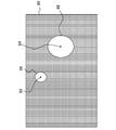
- FIG. 10 shows an example of the position information data output in S48.
- the matching processing unit 54 generates a matching evaluation value distribution in which matching evaluation values are associated with the pixels of the depth image. Then, in the distribution, points 82 and 84 at which the matching evaluation value becomes maximum when the threshold value is greater than or equal to a predetermined threshold are extracted. Further, a template image is arranged around the local maximum points 82 and 84. This template image is obtained by enlarging or reducing the reference template image at the same magnification as the size adjustment at the time of matching evaluation with the local maximum points 82 and 84 as the center.
- regions 86 and 88 that are estimated to be images of a desired object for each of the local maximum points 82 and 84 are represented by distinguishing the region corresponding to the image of the object in the placed template image from the other regions. Is obtained.
- the example of FIG. 10 is an image obtained from the depth image 62 shown in FIG. 7 and representing an area estimated to be a human head with pixel values different from others.
- the resolution of the image 80 output as the position information is not particularly limited. However, when the template image is enlarged, the pixel interval is widened as shown in FIG. 8, so that the region 88 is appropriately interpolated according to the resolution of the image 80. May be represented.
- FIG. 11 is a diagram for explaining a detection region set in the detection process.
- an image 106 shown in the photographed image 104 is obtained by projecting the subject 102 existing in a three-dimensional space (camera coordinate system) having an axis shown in the upper left of FIG.
- the space represented by the captured image 104 increases as the distance in the depth direction increases.
- the divided surfaces are three surfaces parallel to the captured image 104 as shown in the figure.
- the three-dimensional space is divided into frustums by those divisions.
- the subject 102 exists between the distances Z1 and Z2 in the depth direction
- the hand of the subject that appears in the region 108 in the captured image 104 exists in the frustum region 110 in the three-dimensional space.
- the pixel value of the depth image represents the distance in the depth direction of the subject on the image plane of the captured image 104
- the inside / outside determination can be performed by comparing three-dimensional information including the pixel position coordinates and the pixel value with the region 110.
- an area formed by dividing each axis of the three-dimensional space formed by the image plane and the depth direction is set as a detection area, and the object is present in the detection area by comparing with the image in the depth image. Whether the position of the object can be detected. In the simplest case, if all the frustum regions obtained by dividing the three-dimensional space as shown in the figure are set as detection regions, the object can be detected in any detection region regardless of the position. Become.
- the position of the head of the subject 102 is specified by the matching processing unit 54 as described above, the position of the neck or shoulder can be estimated. Therefore, for example, when detecting a hand, one or a plurality of detection areas are set only in an area corresponding to the movable range of the hand with respect to the shoulder. Thereby, the efficiency of the detection process can be remarkably improved, and the possibility that an object other than the hand is included in the detection result can be reduced. As a result, the detection accuracy is also improved.
- the division plane of the area shown in FIG. 11 is merely an example, and for example, the division plane may be different for each detection area. Part of the detection region may overlap.
- the coordinate system for setting the detection area is not limited to the camera coordinate system, and the shape of the detection area may be various.
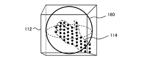
- FIG. 12 is a diagram for explaining a process for determining whether or not an object exists in the set detection area.
- the detection region 112 has a frustum shape as shown in FIG.
- each pixel in the depth image represents position coordinates on the image plane of the subject and distance information in the depth direction, that is, a coordinate point in the three-dimensional space of the camera coordinate system.
- the coordinate points represented by the pixels constituting the hand image 114 in the depth image are present in the detection region 112.
- each pixel is indicated by a black dot.
- the hand can be determined whether or not the hand is in the position based on the presence or absence of a coordinate point in the detection area set in the movable range of the hand estimated from the head.
- a threshold value is provided for the number of coordinate points in determination. Then, it is determined that a hand exists in the detection area where the coordinate point equal to or greater than the threshold value exists.
- the spatial resolution of the coordinate points used for the determination may be the same as or different from the resolution of the depth image.
- FIG. 13 illustrates the coordinate system for setting the detection area and the shape of the detection area.
- the captured image is obtained by projecting a subject within the viewing volume of the frustum onto the image plane, and a wider range of information appears in one pixel as the distance from the imaging device increases. Accordingly, when the ranges of X1 ⁇ X ⁇ X2, Y1 ⁇ Y ⁇ Y2, and Z1 ⁇ Z ⁇ Z2 are set for the coordinate point (X, Y, Z) represented by the pixel of the depth image in the camera coordinate system, the detection region 112 is It becomes a frustum as shown in FIG.
- the optical axis (Z axis) of the imaging device 12 has an inclination with respect to the horizontal plane of the real space as shown in the figure, the vertical direction on the image (Y axis), and hence the vertical direction of the detection area, It will be different from the vertical direction.
- the coordinate system for setting the detection area may not be the camera coordinate system.
- the coordinate point represented by the pixel in the depth image can be converted into a coordinate point in the world coordinate system, and as a result, a detection region 115 can be set for the world coordinate system as shown in FIG. it can.
- the human body is based on an axis perpendicular to the ground or floor, so setting the detection area for the world coordinate system is particularly efficient when detecting the torso or standing feet. It is considered advantageous in terms of accuracy.
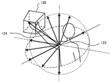
- FIG. 14 is a diagram for explaining the principle of specifying the position of the hand when the presence of a hand is detected in a certain detection region 120.
- the hand moves on a spherical surface centered on the shoulder and elbow.
- the shoulder should be the reference point 122, and the direction in which the hand should face can be determined by the relative position of the detection region 120 with respect to the reference point 122.
- the normal vector at the position of the detection area of the spherical surface passing through the detection area where the presence of the hand is detected with the reference point 122 as the center is determined as the reference vector indicating the direction in which the hand should face.
- the position of a hand is specified by comparing with the coordinate point in a detection area
- the reference points are the shoulder and elbow when the detection target is the fingertip, the shoulder when the elbow is detected, the base of the foot and the knee when the target is the tip of the foot, and the base of the foot when the target is the knee.
- the detection process may be advanced step by step, for example, by first detecting the tip of the elbow using the shoulder as a reference point and then detecting the hand using that point as a reference point.
- the bending angle of the elbow may be estimated according to the distance from the reference point to the hand, and the reference point may be switched between the shoulder and the elbow accordingly. The same applies to the feet.
- FIG. 15 is a diagram for explaining a technique for specifying the position of the hand using a reference vector.
- coordinate points white circles and black circles
- the coordinate point farthest from the reference point 122 in the direction of the reference vector 126 is considered to represent the position of the hand. Therefore, the inner product of the coordinate point vector from the reference point 122 to each coordinate point and the reference vector 126 is calculated, and the inner product values are compared.
- the inner product value is calculated for all coordinate points in the detection area 112, the coordinate points are sorted in descending order, and when a predetermined number of upper coordinate points are extracted, these coordinate points are approximately in the vicinity of the hand. It represents an image. Therefore, it is set as the hand position coordinate by taking the average value of the position coordinates represented by the extracted coordinate points. By adopting an average value of a plurality of coordinate points, it is possible to suppress the influence of noise and errors at the coordinate points. In the calculation of the coordinate point vector, coordinate conversion is appropriately performed so that the coordinate system of the coordinate point and the reference point coincide.
- FIG. 16 is a flowchart showing a processing procedure in which the coordinate point analysis unit 56 of the information processing apparatus 10 detects the hand position in S18 of FIG.
- the coordinate point analysis unit 56 determines a detection region based on the position of the head detected by the matching processing unit 54, and further determines the threshold of the number of coordinate points when determining that a hand is present at the position of the detection region.
- the value is determined (S52). For example, when the right hand is detected, the right shoulder is identified by following the neck, torso, etc. from the head image identified in the depth image, and the spherical surface with the arm length as the radius and the inside Distribute a plurality of detection areas.
- the distribution range of the detection area may be further limited.
- the detection area may be determined around that position. Further, the position of the hand may be predicted from the movement so far and reflected in the setting of the detection area.
- the threshold value set for the number of coordinate points to determine the presence may be determined adaptively according to the position of the detection region. For example, as the distance from the imaging device increases, the space represented by one coordinate point increases, and the coordinate points for the space are dispersed. Therefore, when the detection area is set to the same size in the world coordinate system, the threshold value is reduced as the detection area is farther from the imaging device. Thereby, the presence can be detected with the same degree of accuracy regardless of the distance from the camera.
- the depth value information acquisition accuracy and resolution may differ depending on the shooting environment such as indoor brightness and shooting conditions. Therefore, the threshold value may be switched according to the situation at the time such as the photographing environment. For this reason, information representing the correspondence between various parameters representing the environment and threshold values may be prepared in advance. Next, among the coordinate points in the three-dimensional space represented by the pixels of the depth image, the number of coordinate points existing in the set detection area is counted (S54).
- the processing from S54 to S58 is performed for each detection area.
- FIG. 17 is a flowchart showing a procedure of processing for detecting the position of the hand performed by the coordinate point analysis unit 56 in S58 of FIG.
- an area for which the tip is specified is determined (S60).
- the detection area 112 set for detecting the presence of the hand is used as it is, and the inner product is calculated and compared for the coordinate points in the detection area 112.
- the detection area set for detecting the presence and the area defining the set of coordinate points to be compared with the inner product for detecting the tip may not necessarily be the same.
- the former may be referred to as “presence detection region” and the latter as “tip detection region”.
- FIG. 18 schematically shows an example in which the presence detection area for detecting the presence of the hand is different from the tip detection area for detecting the position of the tip.
- the presence detection areas 140a, 140b, 140c, and 140d are in the four areas.
- a hand may not be included in the presence detection region where the number of coordinate points is equal to or greater than the threshold, such as the presence detection region 140d.
- the number of coordinate points in a plurality of presence detection areas is greater than or equal to a threshold value. Therefore, when a set of coordinate points exists continuously in a plurality of adjacent detection areas, the tip detection area is reset so as to include them.
- the four presence detection areas 140a, 140b, 140c, and 140d may be integrated into one tip detection area.
- a part of the presence detection area may be divided to make the part a tip detection area.
- coordinate points may exist due to noise or errors.
- the detection accuracy is improved by appropriately setting a region where the entire set of coordinate points (clusters) whose presence has been detected and where no extra coordinate points away from the set are included as the tip detection region.
- the number of coordinate points included in the detection area may be acquired while finely adjusting the size of the detection area, and the tip detection area having an appropriate size may be determined based on the change in the number.
- the tip detection region 140d when the tip position is in the vicinity of the end of the region as in the presence detection region 140d, the presence detection regions 140a, 140b, and 140c adjacent to the presence detection region 140d may be included in the tip detection region.
- the coordinate point analysis unit 56 next determines the reference vector for the set tip detection region as described with reference to FIG. 14 (S62), and calculates the inner product with the vector corresponding to each coordinate point (S62). S64). Next, the coordinate points are sorted in descending order of the inner product value, and a predetermined number of upper coordinate points are extracted (S66). Then, by calculating the average value of the position coordinates represented by each coordinate point, the position of the hand is determined (S68).
- the presence detection area and the tip detection area may be set for both the camera coordinate system and the world coordinate system.
- These detection areas may have not only a frustum or a rectangular parallelepiped area obtained by dividing the coordinate axis of each coordinate system, but also an arbitrary three-dimensional shape according to the shape of the detection target, the movable range, and the like.
- FIG. 19 schematically shows an example in which detection areas having a plurality of shapes are set in a plurality of coordinate systems.
- the detection area 150 has a frustum shape set with respect to the camera coordinate system.
- the detection areas 152 and 154 are set with respect to the world coordinate system, and the former has a spherical shape and the latter has a cylindrical shape.
- a person standing upright is close to a cylinder or quadrangular prism with the vertical axis as the axis, so by using such a detection area, the influence of other parts and the surrounding environment on the detection of existence and the detection of the tip Easy to eliminate.
- the movable range can be covered by setting the detection area in a spherical shape with the shoulder as the center.
- the shape of the detection area is appropriately selected from a frustum, a rectangular parallelepiped, a sphere, an ellipsoid, a column, a cone, etc., depending on the object whose presence and tip are to be detected, the intended use of the detection result, etc. Is desirable.
- Different detection areas may be set to a plurality of areas at the same time, and the presence or tip of the object may be detected for each of them.
- FIG. 20 schematically shows an example of a mode in which detection areas of different shapes are set to overlap and detection is performed in stages. In this example, first, the presence of the hand 114 is detected by the frustum detection area 112 set for the camera coordinate system.
- the threshold value for example, a spherical detection area 160 inscribed in the frustum is set, and the number of coordinate points existing in the detection area 112 is set to the threshold value. Compare with The threshold for the frustum and the threshold for the spherical shape may be the same or different. If the number of coordinate points in the spherical detection area 160 is greater than or equal to the threshold value, it is finally determined that there is a hand at that position. Alternatively, the tip is detected based on the coordinate points in the spherical detection area 160.
- the number of frustum detection areas 112 that do not require coordinate transformation and are low in computational load is set to identify a region that is likely to have a hand, and only in that part of the palm
- a configuration in which a spherical detection region 160 close to the shape and movable range is set and the presence and tip are detected with high accuracy can be realized, and both processing efficiency and detection accuracy can be achieved.
- the figure illustrates the frustum and the sphere inscribed therein, the combination of the shapes and the positional relationship may be appropriately selected depending on the shape of the detection target and the characteristics of the movement.
- FIG. 21 is a diagram for explaining a mode of setting a dead area together with a detection area. As illustrated, when detecting a hand including the possibility that the user's 170 hand is in the vicinity of the head, the detection region 172 for that purpose may include an image of the head.
- the detection area 172 since the detection area 172 includes coordinate points representing the head image 176, the number of coordinate points is the threshold value even if the hand is not at that position. If it becomes above, there is a possibility that it is erroneously detected as the presence of a hand. Further, as shown in the figure, even if there is actually a coordinate point representing the hand image 174, the coordinate point representing the head image 176 may cause an error in detection of the tip.
- the insensitive area 178 is set with an ellipsoid centered on the center of the head detected by the matching processing unit 54. Not only the head but also a dead area may be set for a part other than the detection target such as a trunk or a foot.
- the shape of the insensitive region may be appropriately selected according to the shape of the part. By doing so, detection errors can be suppressed even when many detection regions are set over a wide range, or when there is a high possibility that a part to be detected approaches another part.
- the dead area may be set for peripheral objects included in the field of view of the camera, in addition to the part of the same subject.
- FIG. 22 schematically shows an example in which a dead area is set for the floor.
- detection areas 180a, 180b, 180c, etc. which are the movable ranges of the instep of the foot, are set.
- the detection region for detecting the state where the foot is in contact with the floor as in the detection region 180c it is considered that the presence is detected even if there is no foot because the image of the floor is always included. .
- the foot and the floor cannot be distinguished from each other, and the toe cannot be detected.
- FIG. 23 is a diagram for explaining a method for detecting a ceiling surface and a floor surface in such an aspect.
- the right side of the drawing is a schematic diagram 250 of the shooting environment viewed from the side, and the left side is a schematic diagram of an image 252 shot in the shooting environment.
- the imaging device 12 includes an acceleration sensor
- the surface of the ceiling surface 254 and the floor surface 256 with respect to the plane of the photographed image is determined based on the gravity vector 266.
- the height should be specified. Therefore, for example, as shown in the drawing, detection areas 270 and 272 for detecting the presence of the ceiling surface 254 and the floor surface 256 are set so as to be spread on a horizontal plane in the world coordinate system and stacked in a direction perpendicular thereto.
- the detection areas 270 and 272 represented by rectangles are assumed to be rectangular flat plates, but other shapes may be used.
- the height of the floor surface and the ceiling surface is specified based on the number of coordinate points in the detection area. Most simply, the coordinate points existing in the detection region of each height (layer) are summed, and the height at which the most coordinate points are obtained is defined as the floor surface or the ceiling surface.
- the angle of the assumed horizontal plane may be adjusted in consideration of a case where an error occurs between the horizontal plane of the world coordinate system estimated from the gravity vector 266 and the actual horizontal plane.
- FIG. 24 is a diagram for explaining a method of detecting the correct horizontal plane by adjusting the angle of the detection region. The left side of the figure shows a case where the angle between the assumed horizontal plane and the actual floor surface 256 is deviated.
- the detection area having the largest number of coordinate points or the detection area where the number of coordinate points protrudes is extracted by comparing the upper and lower detection areas, and it is estimated that a floor exists at least at that position. To do.
- a detection area 280 is extracted.
- the coordinate points in each detection area set to the same height as the detection area 280 are counted while finely adjusting the assumed horizontal plane angle around the center of gravity of the extracted detection area 280 and the like.
- the detection area 272b when the same coordinate point enters all the detection areas represents the actual floor surface.
- the detection area 272b may be used as a dead area when detecting a toe or the like during actual operation.
- the coordinate point analysis unit 56 detects the floor surface and the ceiling surface using the coordinate points in the detection area, but the matching processing unit 54 detects the floor surface and the ceiling surface by the matching process. It is also possible. In this case, the left and right stereo images are matched.
- the detection surface is set with respect to the assumed horizontal plane in the world coordinate system.
- the detection surface is a surface arbitrarily set in the three-dimensional space in order to determine whether or not there is a subject on the surface.
- the region when the detection surface is projected onto the image plane is cut out from the left and right captured images constituting the stereo image.
- the left or right cutout region is shifted to the left or right by the amount of parallax from the cutout region in the other image.
- the above-described equation (2) can be used for the smoothing amount.
- the feature points extracted at this time are ceiling lighting fixtures, lattice patterns formed by connecting portions of building materials such as tiles, carpet patterns, and the like. If the floor surface and the ceiling surface coincide with the set detection surface, the images cut out from the stereo image in consideration of the parallax are identical in principle. On the other hand, the difference between the two images increases as the floor surface or ceiling surface deviates from the detection surface. Therefore, the detection surface when the sum of the matching evaluation values of the cut-out images is the highest among the detection surfaces set at a plurality of heights and angles can be specified as the floor surface or the ceiling surface.
- a plurality of parallel detection surfaces are distributed in the height direction to perform matching, and among the detection surfaces having a high total evaluation value, the portion with the high evaluation value is the center. Further, it may be a two-stage process in which the angle of the detection surface is adjusted and the matching process is performed again. Regardless of whether the detection area is used or the detection surface is used, if an acceleration sensor is provided in the imaging device 12 to acquire the gravity vector, the angle can be finely adjusted. However, even if there is no acceleration sensor, the floor surface and the like can be accurately detected by adjusting the angle of the assumed horizontal plane as described above.
- insensitive area 180 was set in the area below the floor in order to detect the toes, but when detecting an object in the vicinity of the ceiling, the area above the detected ceiling is detected.
- the area is defined as a dead area.
- a similar method may be applied to a vertical surface to detect a wall surface and set a dead area on the wall surface.
- the dead area may be set for the body of a person other than the user who is the detection target, or for the hand or foot on the opposite side of the detection target hand or foot.
- the body of another person other than the detection target can be specified based on the position of the detected head, the face recognition process for the inside of the head region, and the like.
- the opposite hand and foot of the same person can be discriminated based on the movable range in a very short time from the hand and foot detected in the previous time step. Furthermore, an area where the coordinate point does not change over time for a predetermined time may be extracted as an image of an object such as furniture, and a dead area may be set in the area.
- the insensitive area By setting the insensitive area in a flexible manner in this way, even if the detection target approaches another object, such as a hand touching the body, face, or furniture, the detection accuracy according to the set size of the detection area is improved.
- the influence of can be suppressed. That is, by setting a sufficiently large detection area where the noise error is small and the tip shape can be easily identified, even if other objects easily enter the detection area, the influence can be reduced.
- a detection region of a necessary part such as a hand or a foot is set based on the position of a reference part such as a head detected by template matching. Then, the presence of the target part is detected based on the number of coordinate points in the detection area among the coordinate points when the three-dimensional coordinates represented by the pixels of the depth image are represented in the three-dimensional space.
- a reference point that considers the movement of the human body such as the shoulder and elbow for hands and the base of the foot and knees for feet, is set, and the detection area for the reference point is reached.
- a reference vector representing the direction in which the tip of the target part should face is specified according to the position.
- the coordinate point representing the tip of the target part is extracted, and the position is specified based on the extracted coordinate point.
- the tip portion can be detected with high accuracy by using the constraint condition of the movement of the human body regardless of the direction in which the target region is directed. If the position of the tip portion is known, the state and posture of the entire human body can be specified from the depth image or the photographed image, so that it can be used for various purposes such as games.
- the presence detection area and the tip detection area can be freely set according to the purpose of use and the shape and movement of the target part, so that highly accurate detection can be performed while suppressing the processing load regardless of the usage situation. Further, by setting the insensitive area in the same manner as the detection area, it is possible to accurately detect only the target part without increasing the processing load. For these reasons, it is possible to provide a highly accurate user interface using human movements and to display images with good responsiveness in games and AR. Further, if the detection result is fed back to the imaging conditions in the imaging device 12, a captured image in which exposure is adjusted to an important part in processing such as a face, hand, and foot can be obtained, regardless of the imaging environment such as the brightness of the room. The accuracy of subsequent processing can be further improved.
- Information processing system 10 Information processing device, 12 Imaging device, 16 Display device, 13a 1st camera, 13b 2nd camera, 22 CPU, 24 GPU, 26 Main memory, 42 Image acquisition unit, 44 Input information acquisition unit, 46 Position information generation unit, 48 image storage unit, 50 output information generation unit, 52 depth image acquisition unit, 54 matching processing unit, 56 coordinate point analysis unit.
- the present invention can be used for information processing apparatuses such as computers, game machines, information terminals, image processing apparatuses, and image display apparatuses.
Landscapes
- Engineering & Computer Science (AREA)
- Theoretical Computer Science (AREA)
- General Engineering & Computer Science (AREA)
- Physics & Mathematics (AREA)
- General Physics & Mathematics (AREA)
- Human Computer Interaction (AREA)
- Multimedia (AREA)
- Computer Vision & Pattern Recognition (AREA)
- Health & Medical Sciences (AREA)
- Artificial Intelligence (AREA)
- Computing Systems (AREA)
- Databases & Information Systems (AREA)
- Evolutionary Computation (AREA)
- General Health & Medical Sciences (AREA)
- Medical Informatics (AREA)
- Software Systems (AREA)
- Image Analysis (AREA)
- Length Measuring Devices By Optical Means (AREA)
Abstract
Selon l'invention, une région de détection (112) est définie dans un espace tridimensionnel dans lequel un sujet est présent. Lorsqu'une main réelle entre dans la région de détection (112), des points de coordonnées (des cercles blancs et des cercles noirs) représentés par des pixels formant une image (114) de la main dans une image de profondeur entrent dans ladite région de détection (112). Un vecteur de référence (126) représentant la direction dans laquelle la main est censée être orientée, prenant l'épaule comme point de référence (122), est défini dans la région de détection (112). Les produits internes du vecteur de référence (126) et des vecteurs allant du point de référence (122) à chaque point de coordonnées sont calculés, et les valeurs de produit interne sont comparées. La position du point de coordonnées ayant la plus grande valeur de produit interne est acquise en tant que position de la pointe de la main.
Priority Applications (2)
| Application Number | Priority Date | Filing Date | Title |
|---|---|---|---|
| EP14882680.3A EP3107070B1 (fr) | 2014-02-14 | 2014-12-01 | Dispositif de traitement d'informations et procédé de traitement d'informations |
| US15/115,521 US10210629B2 (en) | 2014-02-14 | 2014-12-01 | Information processor and information processing method |
Applications Claiming Priority (4)
| Application Number | Priority Date | Filing Date | Title |
|---|---|---|---|
| JP2014-026770 | 2014-02-14 | ||
| JP2014026769A JP6165650B2 (ja) | 2014-02-14 | 2014-02-14 | 情報処理装置および情報処理方法 |
| JP2014026770A JP6300560B2 (ja) | 2014-02-14 | 2014-02-14 | 情報処理装置および情報処理方法 |
| JP2014-026769 | 2014-02-14 |
Publications (1)
| Publication Number | Publication Date |
|---|---|
| WO2015122079A1 true WO2015122079A1 (fr) | 2015-08-20 |
Family
ID=53799834
Family Applications (1)
| Application Number | Title | Priority Date | Filing Date |
|---|---|---|---|
| PCT/JP2014/081694 WO2015122079A1 (fr) | 2014-02-14 | 2014-12-01 | Dispositif de traitement d'informations et procédé de traitement d'informations |
Country Status (3)
| Country | Link |
|---|---|
| US (1) | US10210629B2 (fr) |
| EP (1) | EP3107070B1 (fr) |
| WO (1) | WO2015122079A1 (fr) |
Families Citing this family (18)
| Publication number | Priority date | Publication date | Assignee | Title |
|---|---|---|---|---|
| JP6300328B2 (ja) * | 2016-02-04 | 2018-03-28 | 和彦 外山 | 環境音生成装置及びそれを用いた環境音生成システム、環境音生成プログラム、音環境形成方法及び記録媒体 |
| US10277836B2 (en) * | 2016-03-07 | 2019-04-30 | Ricoh Company, Ltd. | Communication terminal, image management apparatus, image processing system, method for controlling display, and computer program product |
| JP6590153B2 (ja) | 2016-03-23 | 2019-10-16 | パナソニックIpマネジメント株式会社 | 投影指示装置、荷物仕分けシステムおよび投影指示方法 |
| US9681096B1 (en) | 2016-07-18 | 2017-06-13 | Apple Inc. | Light field capture |
| WO2018033137A1 (fr) * | 2016-08-19 | 2018-02-22 | 北京市商汤科技开发有限公司 | Procédé, appareil et dispositif électronique d'affichage d'un objet de service dans une image vidéo |
| JP6934618B2 (ja) * | 2016-11-02 | 2021-09-15 | パナソニックIpマネジメント株式会社 | ジェスチャ入力システム及びジェスチャ入力方法 |
| US10614591B2 (en) * | 2017-05-31 | 2020-04-07 | Google Llc | Hand tracking based on articulated distance field |
| DE102017211038A1 (de) * | 2017-06-29 | 2019-01-03 | Robert Bosch Gmbh | Verfahren zum Einstellen einer Kamera |
| US10636173B1 (en) | 2017-09-28 | 2020-04-28 | Alarm.Com Incorporated | Dynamic calibration of surveillance devices |
| US11012683B1 (en) | 2017-09-28 | 2021-05-18 | Alarm.Com Incorporated | Dynamic calibration of surveillance devices |
| US10565719B2 (en) | 2017-10-13 | 2020-02-18 | Microsoft Technology Licensing, Llc | Floor detection in virtual and augmented reality devices using stereo images |
| CN109976590B (zh) * | 2017-12-27 | 2022-04-01 | 上海品奇数码科技有限公司 | 一种基于摄像头的触控检测方法 |
| CN108646931B (zh) * | 2018-03-21 | 2022-10-14 | 深圳市创梦天地科技有限公司 | 一种终端控制方法及终端 |
| US10727215B1 (en) * | 2019-01-30 | 2020-07-28 | Sandisk Technologies Llc | Three-dimensional memory device with logic signal routing through a memory die and methods of making the same |
| CN111080701A (zh) * | 2019-12-13 | 2020-04-28 | 深圳市丰巢科技有限公司 | 智能柜物体检测方法、装置、服务器及存储介质 |
| CN113609917B (zh) * | 2021-07-12 | 2022-09-27 | 深圳市鸿合创新信息技术有限责任公司 | 人手位置信息确定方法及相关设备 |
| JP7233631B1 (ja) | 2022-06-01 | 2023-03-07 | 株式会社ジースポート | 姿勢改善システム |
| CN116228698B (zh) * | 2023-02-20 | 2023-10-27 | 北京鹰之眼智能健康科技有限公司 | 基于图像处理的填充物状态检测方法 |
Citations (8)
| Publication number | Priority date | Publication date | Assignee | Title |
|---|---|---|---|---|
| JPH10143659A (ja) * | 1996-11-06 | 1998-05-29 | Komatsu Ltd | 物体検出装置 |
| JP2008146106A (ja) * | 2006-12-05 | 2008-06-26 | Honda Motor Co Ltd | 三次元物体を検出する装置 |
| JP2011022927A (ja) * | 2009-07-17 | 2011-02-03 | Oki Joho Systems:Kk | 手画像認識装置 |
| JP2012120647A (ja) * | 2010-12-07 | 2012-06-28 | Alpha Co | 姿勢検出装置 |
| JP2012216946A (ja) * | 2011-03-31 | 2012-11-08 | Sony Computer Entertainment Inc | 情報処理装置、情報処理方法、および位置情報のデータ構造 |
| JP2013037467A (ja) * | 2011-08-05 | 2013-02-21 | Toshiba Corp | コマンド発行装置、コマンド発行方法およびプログラム |
| JP2013242812A (ja) * | 2012-05-22 | 2013-12-05 | Sony Computer Entertainment Inc | 情報処理装置および情報処理方法 |
| WO2014128789A1 (fr) * | 2013-02-19 | 2014-08-28 | 株式会社ブリリアントサービス | Dispositif de reconnaissance de forme, programme de reconnaissance de forme et procédé de reconnaissance de forme |
Family Cites Families (9)
| Publication number | Priority date | Publication date | Assignee | Title |
|---|---|---|---|---|
| EP1477924B1 (fr) * | 2003-03-31 | 2007-05-02 | HONDA MOTOR CO., Ltd. | Appareil, procédé et logiciel de reconnaissance des gestes |
| JP2009514106A (ja) | 2005-10-26 | 2009-04-02 | 株式会社ソニー・コンピュータエンタテインメント | コンピュータプログラムとインタフェースするためのシステムおよび方法 |
| US8351651B2 (en) * | 2010-04-26 | 2013-01-08 | Microsoft Corporation | Hand-location post-process refinement in a tracking system |
| US9002099B2 (en) * | 2011-09-11 | 2015-04-07 | Apple Inc. | Learning-based estimation of hand and finger pose |
| EP2634670A1 (fr) * | 2012-03-01 | 2013-09-04 | Asplund Data AB | Dispositif de saisie de données |
| US9041689B1 (en) * | 2012-08-02 | 2015-05-26 | Amazon Technologies, Inc. | Estimating fingertip position using image analysis |
| US9323346B2 (en) * | 2012-12-31 | 2016-04-26 | Futurewei Technologies, Inc. | Accurate 3D finger tracking with a single camera |
| US9129155B2 (en) * | 2013-01-30 | 2015-09-08 | Aquifi, Inc. | Systems and methods for initializing motion tracking of human hands using template matching within bounded regions determined using a depth map |
| US9720506B2 (en) * | 2014-01-14 | 2017-08-01 | Microsoft Technology Licensing, Llc | 3D silhouette sensing system |
-
2014
- 2014-12-01 EP EP14882680.3A patent/EP3107070B1/fr active Active
- 2014-12-01 WO PCT/JP2014/081694 patent/WO2015122079A1/fr active Application Filing
- 2014-12-01 US US15/115,521 patent/US10210629B2/en active Active
Patent Citations (8)
| Publication number | Priority date | Publication date | Assignee | Title |
|---|---|---|---|---|
| JPH10143659A (ja) * | 1996-11-06 | 1998-05-29 | Komatsu Ltd | 物体検出装置 |
| JP2008146106A (ja) * | 2006-12-05 | 2008-06-26 | Honda Motor Co Ltd | 三次元物体を検出する装置 |
| JP2011022927A (ja) * | 2009-07-17 | 2011-02-03 | Oki Joho Systems:Kk | 手画像認識装置 |
| JP2012120647A (ja) * | 2010-12-07 | 2012-06-28 | Alpha Co | 姿勢検出装置 |
| JP2012216946A (ja) * | 2011-03-31 | 2012-11-08 | Sony Computer Entertainment Inc | 情報処理装置、情報処理方法、および位置情報のデータ構造 |
| JP2013037467A (ja) * | 2011-08-05 | 2013-02-21 | Toshiba Corp | コマンド発行装置、コマンド発行方法およびプログラム |
| JP2013242812A (ja) * | 2012-05-22 | 2013-12-05 | Sony Computer Entertainment Inc | 情報処理装置および情報処理方法 |
| WO2014128789A1 (fr) * | 2013-02-19 | 2014-08-28 | 株式会社ブリリアントサービス | Dispositif de reconnaissance de forme, programme de reconnaissance de forme et procédé de reconnaissance de forme |
Non-Patent Citations (1)
| Title |
|---|
| See also references of EP3107070A4 * |
Also Published As
| Publication number | Publication date |
|---|---|
| EP3107070A4 (fr) | 2018-01-17 |
| US20170011519A1 (en) | 2017-01-12 |
| EP3107070B1 (fr) | 2020-04-29 |
| US10210629B2 (en) | 2019-02-19 |
| EP3107070A1 (fr) | 2016-12-21 |
Similar Documents
| Publication | Publication Date | Title |
|---|---|---|
| WO2015122079A1 (fr) | Dispositif de traitement d'informations et procédé de traitement d'informations | |
| US9542755B2 (en) | Image processor and image processing method | |
| JP6548518B2 (ja) | 情報処理装置および情報処理方法 | |
| JP6009502B2 (ja) | 情報処理装置および情報処理方法 | |
| JP6697986B2 (ja) | 情報処理装置および画像領域分割方法 | |
| JP5773944B2 (ja) | 情報処理装置および情報処理方法 | |
| JP6615723B2 (ja) | 情報処理装置および対象物認識方法 | |
| US9460337B2 (en) | Information processor and information processing method | |
| US9628755B2 (en) | Automatically tracking user movement in a video chat application | |
| US20120056982A1 (en) | Depth camera based on structured light and stereo vision | |
| US20150002419A1 (en) | Recognizing interactions with hot zones | |
| JP6352208B2 (ja) | 三次元モデル処理装置およびカメラ校正システム | |
| US9785854B2 (en) | Information processor, information processing method, and computer program | |
| US20160044297A1 (en) | Information processor, information processing method, and computer program | |
| JP6300560B2 (ja) | 情報処理装置および情報処理方法 | |
| JPWO2019003384A1 (ja) | 情報処理装置、情報処理システム、および材質特定方法 | |
| CN113474816A (zh) | 弹性动态投影映射系统和方法 | |
| JPWO2019003383A1 (ja) | 情報処理装置および材質特定方法 | |
| US20130069939A1 (en) | Character image processing apparatus and method for footskate cleanup in real time animation | |
| JP6165650B2 (ja) | 情報処理装置および情報処理方法 | |
| CN109842789A (zh) | 深度感测装置及深度感测方法 |
Legal Events
| Date | Code | Title | Description |
|---|---|---|---|
| 121 | Ep: the epo has been informed by wipo that ep was designated in this application |
Ref document number: 14882680 Country of ref document: EP Kind code of ref document: A1 |
|
| REEP | Request for entry into the european phase |
Ref document number: 2014882680 Country of ref document: EP |
|
| WWE | Wipo information: entry into national phase |
Ref document number: 2014882680 Country of ref document: EP |
|
| WWE | Wipo information: entry into national phase |
Ref document number: 15115521 Country of ref document: US |
|
| NENP | Non-entry into the national phase |
Ref country code: DE |