WO2015122033A1 - 遠隔サーバ - Google Patents
遠隔サーバ Download PDFInfo
- Publication number
- WO2015122033A1 WO2015122033A1 PCT/JP2014/067141 JP2014067141W WO2015122033A1 WO 2015122033 A1 WO2015122033 A1 WO 2015122033A1 JP 2014067141 W JP2014067141 W JP 2014067141W WO 2015122033 A1 WO2015122033 A1 WO 2015122033A1
- Authority
- WO
- WIPO (PCT)
- Prior art keywords
- fuel
- engine
- exhaust temperature
- information
- engine exhaust
- Prior art date
- Legal status (The legal status is an assumption and is not a legal conclusion. Google has not performed a legal analysis and makes no representation as to the accuracy of the status listed.)
- Ceased
Links
Images







Classifications
-
- F—MECHANICAL ENGINEERING; LIGHTING; HEATING; WEAPONS; BLASTING
- F02—COMBUSTION ENGINES; HOT-GAS OR COMBUSTION-PRODUCT ENGINE PLANTS
- F02D—CONTROLLING COMBUSTION ENGINES
- F02D41/00—Electrical control of supply of combustible mixture or its constituents
- F02D41/02—Circuit arrangements for generating control signals
- F02D41/14—Introducing closed-loop corrections
- F02D41/1438—Introducing closed-loop corrections using means for determining characteristics of the combustion gases; Sensors therefor
- F02D41/1444—Introducing closed-loop corrections using means for determining characteristics of the combustion gases; Sensors therefor characterised by the characteristics of the combustion gases
- F02D41/1446—Introducing closed-loop corrections using means for determining characteristics of the combustion gases; Sensors therefor characterised by the characteristics of the combustion gases the characteristics being exhaust temperatures
-
- F—MECHANICAL ENGINEERING; LIGHTING; HEATING; WEAPONS; BLASTING
- F02—COMBUSTION ENGINES; HOT-GAS OR COMBUSTION-PRODUCT ENGINE PLANTS
- F02D—CONTROLLING COMBUSTION ENGINES
- F02D41/00—Electrical control of supply of combustible mixture or its constituents
- F02D41/0025—Controlling engines characterised by use of non-liquid fuels, pluralities of fuels, or non-fuel substances added to the combustible mixtures
-
- F—MECHANICAL ENGINEERING; LIGHTING; HEATING; WEAPONS; BLASTING
- F02—COMBUSTION ENGINES; HOT-GAS OR COMBUSTION-PRODUCT ENGINE PLANTS
- F02D—CONTROLLING COMBUSTION ENGINES
- F02D2200/00—Input parameters for engine control
- F02D2200/02—Input parameters for engine control the parameters being related to the engine
- F02D2200/06—Fuel or fuel supply system parameters
- F02D2200/0611—Fuel type, fuel composition or fuel quality
Definitions
- the present invention relates to a technique for detecting mixing of an irregular fuel different from regular fuel in a working machine or the like provided with an engine and a fuel tank for storing fuel supplied to the engine.
- Patent Document 1 discloses that in a working machine including an engine and a fuel tank that stores fuel supplied to the engine, when a mixture of illegal fuel is detected using a tank weight measuring device or a fuel property sensor, The structure which transmits that to the work command center is disclosed (refer FIG. 4, FIG. 5 and the paragraphs [0026] and [0028] of patent document 1).
- Patent Document 1 is a configuration that separately requires a tank weight measuring device and a fuel property sensor for detecting mixing of illegal fuel, and the detection configuration for detecting mixing of irregular fuel is complicated.
- the present invention provides a detection configuration for detecting the mixing of irregular fuel such as a tank weight measuring device and a fuel property sensor as in the conventional configuration in a working machine having an engine and a fuel tank for storing fuel supplied to the engine. It is an object of the present invention to provide a configuration capable of detecting the mixing of irregular fuel without providing the.
- the engine exhaust temperature which is the engine exhaust temperature with irregular fuel, varies with the engine exhaust temperature with regular fuel.
- the regular fuel is light oil
- mixing kerosene with light oil increases the engine exhaust temperature at the same output, the same rotation, and the same ambient temperature.
- the working machine or the ship is provided with the working machine or the ship provided with an engine and a fuel tank that stores fuel supplied to the engine.
- Supply information indicating whether or not fuel is supplied to the fuel tank as the operation data from the work machine or the vessel
- an engine exhaust temperature that is an exhaust temperature of the engine
- a fuel supply timing is determined based on the fuel supply information, and based on a change state of the engine exhaust temperature in a period sandwiching the determined fuel supply timing
- a remote server characterized by detecting the mixing of an irregular fuel different from regular fuel.
- “regular fuel” refers to fuel that is listed in product specifications such as catalogs and instructions for use and that has been properly sold (for example, fuel that is regularly charged with light oil take-off tax). is there.
- product specifications such as catalogs and instructions for use describe that light oil is used for the engine in the working machine or the ship
- a mixed fuel obtained by mixing fuel other than light oil such as kerosene into light oil
- fuels other than light oil such as kerosene are “unusual fuels”.
- the fuel supply information indicating whether or not fuel is supplied to the fuel tank open / close information indicating whether or not a door in the fuel tank has been opened and closed, and a remaining amount of fuel in the fuel tank are detected.
- the remaining amount information indicating the remaining amount of fuel in the fuel tank from a remaining amount sensor can be exemplified.
- the fuel supply timing can be reliably determined by detecting the opening / closing information, and when the fuel supply information is the remaining amount information, The fuel supply timing can be reliably determined by detecting that the amount of fuel in the fuel tank has increased based on the quantity information.
- the opening / closing information is detected, and by detecting that the fuel in the fuel tank has increased by the remaining amount information, It is possible to more reliably determine the fuel supply timing.
- a management source of the work implement or the ship is identified based on the identification information that has detected the irregular fuel, and the irregular fuel is mixed into the work implement or the vessel in the identified management source.
- a mode of notifying that there is a possibility of being performed can be illustrated.
- an irregular fuel such as a tank weight measuring device or a fuel property sensor as in a conventional configuration in a working machine or ship equipped with an engine and a fuel tank for storing fuel supplied to the engine. It is possible to detect the entry of irregular fuel without providing a detection configuration for detecting the entry of fuel.
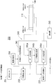
- FIG. 1 is a schematic configuration diagram schematically showing a remote monitoring system for remotely monitoring an agricultural machine.
- FIG. 2 is a block diagram illustrating a schematic configuration of an agricultural machine including a remote monitoring terminal device.
- FIG. 3 is a block diagram showing a schematic configuration of a remote monitoring terminal device in an agricultural machine.
- FIG. 4 is an operation diagram schematically showing an operation process of various data transmission functions by various data transmission control units in the control unit of the remote monitoring terminal device.
- FIG. 5 is a data structure diagram schematically illustrating an example of data stored in various data storage units of the remote monitoring terminal device.
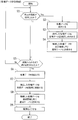
- FIG. 6 is a flowchart illustrating an example of a control operation performed by various data transmission control units.
- FIG. 1 is a schematic configuration diagram schematically showing a remote monitoring system for remotely monitoring an agricultural machine.
- FIG. 2 is a block diagram illustrating a schematic configuration of an agricultural machine including a remote monitoring terminal device.
- FIG. 3 is a block diagram showing a schematic configuration of a remote monitoring terminal device in an
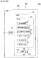
- FIG. 7 is a block diagram illustrating a schematic configuration of a control unit in the remote server according to the first embodiment.
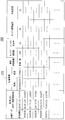
- FIG. 8 is a chart showing an example of a first conversion table of the reference engine exhaust temperature with the normal fuel according to the engine load factor with respect to the engine speed.
- FIG. 9 is a chart showing an example of a second conversion table of the reference engine exhaust temperature with the normal fuel according to the engine load factor with respect to the engine speed.
- FIG. 10 is a data structure diagram schematically illustrating an example of data including identification information, management source information, and irregular fuel detection date and time stored in the storage unit when the irregular fuel is detected.
- FIG. 11 is a flowchart illustrating an example of a control operation performed by the control unit in the remote server according to the first embodiment.
- FIG. 12 is a block diagram illustrating a schematic configuration of a control unit in the remote server according to the second embodiment.
- FIG. 13 is a chart showing an example of a setting table for storing in the storage unit the engine exhaust temperature corresponding to the engine load factor with respect to the engine speed for each temperature range of the outside air temperature.
- FIG. 14 is a flowchart illustrating an example of a control operation by the control unit in the remote server according to the second embodiment.
- FIG. 1 is a schematic configuration diagram schematically showing a remote monitoring system 100 for remotely monitoring agricultural machines 110.
- FIG. 2 is a block diagram illustrating a schematic configuration of the agricultural machine 110 including the remote monitoring terminal device 200.
- FIG. 3 is a block diagram showing a schematic configuration of the remote monitoring terminal device 200 in the agricultural machine 110.
- the remote monitoring system 100 includes one or a plurality (here, a plurality) of agricultural machines (an example of a work machine) 110,. 200, and a remote server 130 connected to the remote monitoring terminal device 200 via a communication network 140.
- the remote server 130 is disposed in the remote monitoring center 120 located far away from the agricultural machines 110, and collects predetermined predetermined operation data that is data relating to the operating state of the agricultural machines 110. Accumulate.
- the remote server 130 is connected to a terminal device 160 such as a personal computer, a tablet computer, or a mobile terminal via a network 150 such as a LAN (Local Area Network) or the Internet. ,... Are used by users of the agricultural machine 110 and users such as dealers.
- the remote monitoring terminal device 200 and the remote server 130 have communication units 210 and 131 (specifically, communication modules), and are connected by the communication units 210 and 131 via the communication network 140.
- communication units 210 and 131 specifically, communication modules
- the remote server 130 can remotely monitor the agricultural machines 110,... By the user at the remote monitoring center 120.
- the communication network 140 may be a wired communication network, a wireless communication network, or a combination of a wired communication network and a wireless communication network.
- the communication network 140 is typically a public line network provided by a telecommunications carrier and can be a public line network in which terminals such as fixed telephones and mobile phones communicate with each other.
- the agricultural machine 110 includes one or a plurality (here, a plurality) of working units 111,.
- the working units 111 For example, when the agricultural machine is a combine, a traveling working unit, a mowing working unit, a threshing working unit, and the like can be given.
- Each work unit 111,... Is provided with an electronic control device (specifically, a controller) 113,.
- the electronic control devices 113,... command various actuators (not shown), and appropriately control the operating states of the working units 111,.
- Each of the electronic control devices 113,... Is adapted to transfer data to each other based on the CAN (Controller Area Network) standard.
- each electronic control unit 113 Goes to each work unit 111,... Based on detection value information (signals) detected by various sensors in each work unit 111,. The operation state is controlled. Moreover, each electronic control unit 113,... Appropriately determines whether or not an abnormality such as a failure of the agricultural machine 110 has occurred, and if an abnormality has occurred, error information corresponding to the abnormality is generated. (Specifically, an error code) is generated.
- a working unit (running working unit 111a) that operates the engine 112 monitors the engine 112, the rotational speed of the engine 112, a load state, and the like, and determines an optimal injection pressure and injection timing to the fuel system.
- the electronic control unit 113 (engine controller 113a) performs operation start / pause operation and operation state control by driving the engine 112 in addition to operation control of the working unit 111 (traveling work unit 111a). It has become.
- the battery BT is appropriately charged by the electric power supplied from the generator 114.
- the start switch SW provided in the working unit 111 is a changeover switch that selectively switches between a power-on state and a power-off state.
- the power-on state is a state in which power is supplied from the battery BT to the control unit 240 (see FIG. 3) and the electronic control device 113 (engine controller 113a) in the remote monitoring terminal device 200.
- the power-off state is a state in which power supply from the battery BT to the control unit 240 and the electronic control device 113 (engine controller 113a) in the remote monitoring terminal device 200 is cut off.
- the battery BT is connected to both the power connection line L1 connected to the control unit 240 and the power connection line L2 connected to the electronic control device 113 (engine controller 113a) via the start switch SW. Connected.
- the start switch SW is a so-called key switch
- the “ON” terminal is a connection terminal of the power supply connection lines L1 and L2.
- the “OFF” terminal is a terminal when the start switch SW is in an OFF state.
- the battery BT and the power control unit 220 in the remote monitoring terminal device 200 are connected via the power connection line L3.
- the remote monitoring terminal device 200 supplies power to the communication unit 210, a control unit 240 that performs transmission / reception of data during communication, various input / output controls and arithmetic processing control, and the control unit 240.
- Power supply control unit 220 As shown in FIG. 3, the remote monitoring terminal device 200 supplies power to the communication unit 210, a control unit 240 that performs transmission / reception of data during communication, various input / output controls and arithmetic processing control, and the control unit 240.
- Power supply control unit 220 Power supply control unit 220.
- the communication unit 210 can communicate using the same communication protocol (communication protocol) as the communication unit 131 of the remote server 130 in the remote monitoring center 120 (see FIG. 1). Data transmitted / received during communication is converted by the communication unit 210 so as to follow the communication protocol. Then, the communication unit 210 transmits the operation data of the agricultural machine 110 acquired by the control unit 240 to the remote server 130.
- communication protocol communication protocol
- the power control unit 220 is connected to the battery BT regardless of whether the start switch SW is off or on. Specifically, an input side power line (not shown) of the power controller 220 and the battery BT are connected by a power connection line L3. As a result, the power controller 220 is constantly supplied with power from the battery BT.
- the power supply line (not shown) of the control unit 240 and the output side power supply line (not shown) of the power supply control unit 220 are connected by the power supply connection line L4.
- the remote monitoring terminal device 200 includes a GPS sensor (an example of a position sensor) 231 that receives radio waves from a GPS (Global Positioning System) satellite, and an agricultural machine based on the radio waves received by the GPS sensor 231.
- 110 further includes a position detection unit 232 that detects position information of 110, and various data storage units 233 that temporarily store various data such as position information detected by the position detection unit 232.
- the GPS sensor 231 is configured to receive radio waves (information including world standard date and time) from GPS satellites.
- the global standard date and time means Coordinated Universal Time (UTC: Universal Time, Coordinated).
- the position detection unit 232 can detect the speed information of the agricultural machine 110 and the direction information of the agricultural machine 110 in addition to the current location information where the agricultural machine 110 is located. That is, the position information includes information on the latitude, longitude, speed, and direction of the agricultural machine 110.
- the position detector 232 constitutes a GPS satellite system (positioning system) together with the GPS sensor 231 and the GPS satellite.
- the various data storage unit 233 includes a non-volatile memory such as a flash memory.
- the various data storage units 233 are connected to the power supply control unit 220, and are always supplied with power from the battery BT.
- the control unit 240 includes a processing unit 250 including a microcomputer such as a CPU (Central Processing Unit), a non-volatile memory such as a ROM (Read Only Memory), and a volatile memory such as a RAM (Random Access Memory). And a time acquisition timer 270 having a clock function for obtaining date and time information of the remote monitoring terminal device 200, and various data transmission control units 241.
- a processing unit 250 including a microcomputer such as a CPU (Central Processing Unit), a non-volatile memory such as a ROM (Read Only Memory), and a volatile memory such as a RAM (Random Access Memory).
- a time acquisition timer 270 having a clock function for obtaining date and time information of the remote monitoring terminal device 200, and various data transmission control units 241.
- the control unit 240 controls the operation of various components by causing the processing unit 250 to load and execute a control program stored in advance in the ROM of the storage unit 260 on the RAM of the storage unit 260. .
- Each agricultural machine 110 Detects a fuel supply information detection unit 171 that detects fuel supply information F that indicates whether or not fuel is supplied to the fuel tank 170, and an engine speed C that is the speed of the engine 112.
- An exhaust temperature detection unit 174 and an outside air temperature detection unit 175 that detects an outside air temperature To around the agricultural machine 110 are further provided.
- the engine rotational speed C means the rotational speed (rotational speed) of the engine 112 per unit time
- the engine load factor R is the ratio of the current injection amount to the maximum fuel injection amount (rated injection amount) ( That is, the fuel injection rate).
- the fuel supply information detection unit 171 includes an open / close sensor that detects open / close information indicating whether or not a door (specifically, a fuel supply cap 170a) in the fuel tank 170 is opened and closed, and is connected to an input system of the control unit 240. ing.
- the fuel supply information detection unit 171 replaces or in addition to the open / close sensor, a remaining amount sensor that detects the remaining amount of fuel in the fuel tank 170 (for example, a sensor that detects the weight of the fuel or a sensor that detects the volume of the fuel). ).
- the engine rotation speed detection unit 172 has a rotation angular velocity sensor that detects the rotation angular velocity of the engine 112, and is connected to the input system of the control unit 240.
- the engine load factor detection unit 173 has a throttle opening sensor that detects the throttle opening of the throttle valve in the engine 112, and is connected to the input system of the control unit 240.
- the engine exhaust temperature detection unit 174 has an exhaust temperature sensor provided in a component of the agricultural machine 110 in the passage region of exhaust gas discharged from the engine 112, and is connected to the input system of the control unit 240.
- the outside air temperature detection unit 175 has an outside air temperature sensor provided near the outside of the agricultural machine 110 and is connected to the input system of the control unit 240.
- the control unit 240 in the agricultural machine 110 includes fuel supply information detection means Pa1, engine speed detection means Pa2, engine load factor detection means Pa3, engine exhaust temperature detection means Pa4, outside air temperature detection means Pa5, and position information. It is set as the structure provided with detection means Pa6.
- the fuel supply information detection means Pa1 detects whether or not the door (specifically, the fuel supply cap 170a) in the fuel tank 170 is opened or closed by an open / close sensor in the fuel supply information detection unit 171 to thereby supply fuel to the fuel tank 170. Is configured to detect whether or not is supplied. That is, the fuel supply information detection unit Pa1 can be regarded as having supplied fuel to the fuel tank 170 by detecting that the door of the fuel tank 170 is opened and closed.
- the fuel supply information detection unit Pa1 is a remaining amount sensor in the fuel supply information detection unit 171 when the fuel supply information detection unit 171 has a remaining amount sensor that detects the remaining amount of fuel in the fuel tank 170.
- the fuel supply information detection means Pa1 can be regarded as having supplied the fuel to the fuel tank 170 by detecting that the fuel in the fuel tank has increased.
- the engine speed detecting means Pa2 is configured to detect the engine speed C by detecting the rotational angular speed of the engine 112 with a rotational angular speed sensor in the engine speed detecting unit 172.
- the engine load factor detecting means Pa3 is configured to detect the engine load factor R by detecting the throttle opening of the throttle valve in the engine 112 by the throttle opening sensor in the engine load factor detector 173.
- the engine exhaust temperature detection means Pa4 is configured to detect the engine exhaust temperature Te using an exhaust temperature sensor in the engine exhaust temperature detection unit 174.
- the outside air temperature detecting means Pa5 is configured to detect the outside air temperature To using the outside air temperature sensor in the outside air temperature detecting unit 175.
- the position information detecting means Pa6 is configured to detect the position information G of the agricultural machine 110.
- the position information G can be obtained from information on the latitude, longitude, speed, and direction of the agricultural machine 110 detected by the GPS sensor 231.
- the various data transmission control unit 241 in the control unit 240 has various data transmission functions.
- FIG. 4 is an operation diagram schematically showing an operation process of various data transmission functions by the various data transmission control unit 241 in the control unit 240 of the remote monitoring terminal device 200.
- FIG. 5 is a data structure diagram schematically illustrating an example of data stored in the various data storage unit 233 of the remote monitoring terminal device 200.
- the various data transmission control unit 241 of the remote monitoring terminal device 200 acquires the acquisition date and time (specifically, a global standard) every predetermined period (for example, 30 seconds) during operation of the agricultural machine 110. , Year, month, day, hour, minute, second), position information G (latitude, longitude, etc.) of the agricultural machine 110, fuel supply information F, engine speed C, engine load factor R, engine exhaust temperature Te and the outside temperature To are acquired and stored in various data storage units 233.
- the various data transmission control unit 241 also stores the acquisition date and time, position information G, fuel supply information F, engine speed C, engine load factor R, engine exhaust temperature Te, and outside air temperature To stored at predetermined intervals in a remote server. To 130.
- the various data transmission control unit 241 obtains acquisition date / time, position information G, fuel supply information F, engine speed C, engine load factor every predetermined cycle (for example, 30 seconds) while the start switch SW is on.
- R data acquisition unit 241a for acquiring engine exhaust temperature Te and outside air temperature To, acquisition date and time acquired by data acquisition unit 241a, position information G, fuel supply information F, engine speed C, engine load factor R, engine
- the exhaust gas temperature Te and the outside air temperature To are configured to function as an operation unit including a data storage control unit 241b that temporarily stores the various data storage unit 233.
- the various data storage unit 233 of the remote monitoring terminal device 200 has an acquisition date and time for each predetermined period acquired by the data acquisition unit 241 a and the data storage control unit 241 b of the various data transmission control unit 241.
- the position information G, fuel supply information F, engine speed C, engine load factor R, engine exhaust temperature Te, and outside air temperature To are stored.
- the various data transmission control unit 241 includes the acquisition date and time, the position information G, the fuel supply information F, the engine speed C, the engine load factor R, the engine stored in the various data storage unit 233.
- the exhaust air temperature Te and the outside air temperature To are configured to function also as an operation unit including a data transmission unit 241c that transmits the communication unit 210 to the remote server 130 (see FIG. 1).
- the control unit 240 does not turn off the power supply by the power supply control unit 220, and the data storage control unit 241b stores various data in the various data storage unit 233. After the various data are transmitted to the remote server 130, the power control unit 220 turns off the power.
- the remote monitoring terminal device 200 converts various data into a format according to the communication protocol of the communication unit 131 of the remote server 130 by the communication unit 210 and then transmits the data to the remote server 130 via the communication network 140 and the communication unit 131. To do.
- FIG. 6 is a flowchart showing an example of the control operation by the various data transmission control unit 241.
- the various data transmission control unit 241 determines whether or not a predetermined period (for example, 30 seconds) has arrived (step S1).
- a predetermined period for example, 30 seconds
- the process proceeds to step S5, while when the predetermined period (for example, 30 seconds) has arrived (step S1: Yes), the GPS sensor 231, Various data of acquisition date / time, position information G, fuel supply information F, engine speed C, engine load factor R, engine exhaust temperature Te, and outside air temperature To are detected by the position detection unit 232 and the data acquisition unit 241a (see FIG. 4).
- the detected various data is stored in the various data storage unit 233 (see FIG. 4) by the data storage control unit 241b (see FIG. 4) (step S3).
- the various data transmission control unit 241 stores the acquisition date / time, position information G, fuel supply information F, engine speed C, engine load factor R, engine exhaust temperature Te, and outside air temperature To stored in the various data storage unit 233.
- Various data is transmitted to the remote server 130 together with identification information (here, a terminal telephone number) that is information for identifying the work machine 110 (step S4).
- Step S5 the various data transmission control unit 241 performs the processes of Steps S1 to S5 until the start switch SW is turned off (Step S5: No).
- the various data transmission control unit 241 receives an OFF operation of the start switch SW (step S5: Yes)
- the GPS sensor 231, the position detection unit 232, and the data acquisition unit 241a acquire the acquisition date and time, the position information G, and the fuel supply information.
- Various data of F, engine speed C, engine load factor R, engine exhaust temperature Te, and outside air temperature To are detected (step S6), and the detected various data are stored in the various data storage unit 233 by the data storage control unit 241b. (Step S7).
- the various data transmission control unit 241 performs various acquisition date / time, position information G, fuel supply information F, engine speed C, engine load factor R, engine exhaust temperature Te, and outside air temperature To stored in the various data storage unit 233.
- the data is transmitted to the remote server 130 together with the identification information (here, the terminal phone number) (step S8), the power control unit 220 turns off the power (step S9), and the process is terminated.
- the process of step S4 may be omitted, and all the various data may be transmitted by the process of step S8.
- FIG. 7 is a block diagram illustrating a schematic configuration of the control unit 132 in the remote server 130 of the first embodiment.
- the remote server 130 provided in the remote monitoring center 120 includes a communication unit 131 and a control unit 132 that controls transmission / reception of data, various input / output controls, and arithmetic processing during communication. ing.
- the communication unit 131 is communicable with the same communication protocol (communication protocol) as the communication unit 210 (see FIGS. 1 to 4) of the remote monitoring terminal device 200. Data transmitted and received at the time of communication is converted by the communication unit 131 so as to comply with the communication protocol. The communication unit 131 receives various data such as the operation data described above.
- the control unit 132 includes a processing unit 133 including a microcomputer such as a CPU (Central Processing Unit), a nonvolatile memory such as a ROM (Read Only Memory), a volatile memory such as a RAM (Random Access Memory), a hard disk device, and a flash. And a storage unit 134 including a rewritable nonvolatile memory such as a memory.
- a processing unit 133 including a microcomputer such as a CPU (Central Processing Unit), a nonvolatile memory such as a ROM (Read Only Memory), a volatile memory such as a RAM (Random Access Memory), a hard disk device, and a flash.
- a storage unit 134 including a rewritable nonvolatile memory such as a memory.
- the control unit 132 controls the operation of various components by causing the processing unit 133 to load and execute a control program stored in advance in the ROM of the storage unit 134 on the RAM of the storage unit 134. .
- the control part 132 in the remote server 130 of 1st Embodiment uses the fuel supply information F which shows whether the fuel was supplied to the fuel tank 170 as operation data from each agricultural machine 110, ..., and engine exhaust temperature Te. Receiving various data, determining the fuel supply timing based on the fuel supply information F, and the irregular fuel different from the regular fuel based on the change state of the engine exhaust temperature Te during the determined fuel supply timing It is set as the structure which detects mixing of.
- control unit 132 in the remote server 130 has an engine exhaust temperature that deviates from the reference engine exhaust temperature Ts after the fuel supply timing among the engine exhaust temperatures Te received from the plurality of agricultural machines 110. It is configured to detect that irregular fuel is mixed in Te agricultural machine 110 (specifically, fuel tank 170). That is, the control unit 132 of the first embodiment is configured to include reception control means P1, fuel supply timing determination means P2, and irregular fuel mixture detection means P3.
- the reception control means P1 includes the acquisition date and time, position information G, fuel supply information F, engine speed C, engine load factor R, engine exhaust temperature Te, and the like transmitted from the various data transmission control units 241 in each agricultural machine 110,. It is set as the structure which receives outside temperature To for every identification information (here terminal telephone number) from each agricultural machine 110, ....
- the storage unit 134 stores a database DB (see FIG. 7) in which model information (specifically, model code and / or model name) and model number information are associated with identification information (here, a terminal phone number) and stored. Is stored in advance, and the control unit 132 may recognize model information (specifically, model code and / or model name) and model number information by referring to the database DB in the storage unit 134 from the identification information. it can.
- the fuel supply timing determination means P2 is configured to determine the fuel supply timing for each model information and machine number information based on the model supply information received by the reception control means P1 and the fuel supply information for each machine number information.
- the fuel supply timing is determined by detecting opening / closing information indicating whether or not a door (specifically, a fuel supply cap 170a) in the fuel tank 170 is opened / closed.
- the irregular fuel mixture detection means P3 is irregular depending on the difference between the engine exhaust temperature Te and the reference engine exhaust temperature Ts after the fuel supply timing for each model information and machine number information determined by the fuel supply timing determination means P2. It is configured to detect mixing of fuel for each model information and machine number information.
- the storage unit 134 converts the engine speed C and the engine load factor R into a reference engine exhaust temperature Ts that is an engine exhaust temperature with normal fuel corresponding to the engine load factor R with respect to the engine speed C.
- a first conversion table TB1 (see FIG. 8 described later) is preset (stored) for each model information.
- FIG. 8 is a chart showing an example of the first conversion table TB1 of the reference engine exhaust temperature Ts with the normal fuel according to the engine load factor R with respect to the engine speed C.
- the engine speed exceeds 0 rpm (revolution per minute) to 200 rpm or less, exceeds 200 rpm to 400 rpm or less, exceeds 400 rpm to 600 rpm or less, exceeds 600 rpm.
- the engine load factor exceeds 0% to 10% or less, exceeds 10% to 20% or less, exceeds 20% to 30% or less, exceeds 30% to 40% or less, exceeds 40% to 50% 50 Over 60%, over 60% over 70%, over 70% over 80%, over 80% over 90%, over 90% over 100%, engine A temperature range of the reference engine exhaust temperature Ts corresponding to each segment of the engine load factor with respect to each segment of the rotational speed is set in advance.
- the temperature range of the reference engine exhaust temperature Ts can be obtained in advance through experiments or the like.
- the irregular fuel mixture detection means P3 determines that the engine exhaust temperature Te is the reference engine exhaust temperature in the first conversion table TB1 from the time when the fuel supply timing determination means P2 determines that the fuel has been supplied. When it is within the temperature range of Ts, it is detected that the regular fuel is supplied to the fuel tank 170, and when it is not within the temperature range, it is detected that the irregular fuel is mixed into the fuel tank 170. It is supposed to be configured.
- the storage unit 134 (see FIG. 7) is provided with an initial state flag FL indicating an initial state (new state) in which no fuel has been supplied in the agricultural machine 110 for each model information and machine number information.
- the initial state flag FL for each model information and machine number information is in an off state (specifically, “0”).
- the storage unit 134 includes a normal number corresponding to the engine load factor R with respect to the engine speed C from the engine speed C and the engine load factor R instead of or in addition to the first conversion table TB1.
- a second conversion table TB2 (see FIG. 9 to be described later) for conversion to the reference engine exhaust temperature Ts with the fuel is set (stored) for each model information.
- the control unit 132 includes a conversion table generating unit P4 (see FIG. 7) that generates the second conversion table TB2 for each model information.
- the conversion table generating unit P4 performs the initial fuel supply from the initial state of each agricultural machine 110,... (Specifically, the initial state flag FL in the storage unit 134 is off) by the fuel supply timing determination unit P2. Model information and machine received by the reception control means P1 from each agricultural machine 110,... Until it is determined that there is (specifically, until the ON state of the initial state flag FL in the storage unit 134 is determined)
- the second conversion table of the storage unit 134 for each model information with the temperature range from the minimum value to the maximum value of the engine exhaust temperature Te corresponding to the engine load factor R for the actual engine speed C for each number information as the reference engine exhaust temperature Ts. Set (store) in TB2.
- the temperature range of the reference engine exhaust temperature Ts set in the second conversion table TB2 can be set after a predetermined time has elapsed (after the engine exhaust temperature Te has stabilized to some extent).
- the conversion table generating unit P4 determines that the first fuel supply has been made, the conversion table generating unit P4 cancels the initial state for each model information and machine number information (specifically, the initial state flag FL in the storage unit 134 is turned on). State "1").
- FIG. 9 is a chart showing an example of the second conversion table TB2 of the reference engine exhaust temperature Ts with the normal fuel according to the engine load factor R with respect to the engine speed C.
- the blank portion of the reference engine exhaust temperature Ts in FIG. 9 obtains the engine exhaust temperature Te corresponding to the engine load factor R with respect to the engine speed C until it is determined from the initial state that the first fuel supply has been performed. This indicates that there is no engine exhaust temperature data.
- the irregular fuel mixture detection means P3 determines that the engine exhaust temperature Te is the reference engine exhaust temperature in the second conversion table TB2 from the time when the fuel supply timing determination means P2 determines that the fuel is supplied. When it is within the temperature range of Ts, it is detected that the regular fuel is supplied to the fuel tank 170, and when it is not within the temperature range, it is detected that the irregular fuel is mixed into the fuel tank 170. It is supposed to be configured.
- the engine exhaust temperature Te usually changes according to the outside air temperature To. That is, the higher the outside air temperature To, the higher the engine exhaust temperature Te, and the lower the outside air temperature To, the lower the engine exhaust temperature Te.
- the first conversion table TB1 is preset (stored) for each set temperature range of the outside air temperature To, and the first conversion table TB1 is stored for each set temperature range of the outside air temperature To. 2 conversion table TB2 is set (stored).
- the first conversion table TB1 and the second conversion table TB2 are not shown, but the conversion table when the outside air temperature is 0 ° C. or lower and the conversion when the outside air temperature is higher than 0 ° C. and lower than 15 ° C.
- the first conversion table TB1 and the second conversion table TB2 in the case where the outside air temperature exceeds 15 ° C. and is 30 ° C. or less are illustrated.
- control unit 132 identifies the management source of the agricultural machine 110 based on the identification information (specifically, model information and machine number information) from which the irregular fuel has been detected. It is configured to further include mixing notification means P5 (see FIG. 7) for notifying that there is a possibility that an irregular fuel has been mixed into the agricultural machine 110 corresponding to the identification information.
- the mixing notification means P5 is a management source of the agricultural machine 110 (for example, a rental company that manages the agricultural machine 110 or the like corresponding to the identification information (specifically, model information and machine number information) that detected the irregular fuel. (E-mail address of the service center) is identified, and the identified management source is notified that there is a possibility that the irregular fuel has been mixed in the agricultural machine 110 corresponding to the identification information in which the irregular fuel has been detected (for example, the agriculture concerned) Send an email to the email address of the rental company or service center that manages the machine 110).
- the identification information specifically, model information and machine number information
- control unit 132 uses information indicating the possibility of mixing of unauthorized fuel as a history in association with identification information (specifically, model information and machine number information) in which the unauthorized fuel is detected.
- identification information specifically, model information and machine number information
- a history storage means P6 for saving is further provided.
- the history storage unit P6 identifies the identification information that detected the irregular fuel and information indicating that the irregular fuel has been detected in association with the management source corresponding to the identification information (in this example, when the irregular fuel is detected).
- the date and time of the irregular fuel detection is stored in the storage unit 134.
- FIG. 10 is a data structure diagram schematically showing an example of data including identification information, management source information, and irregular fuel detection date and time stored in the storage unit 134 when irregular fuel is detected.
- the storage unit 134 detects the irregular fuel for the management source information corresponding to the identification information (specifically, model information and machine number information).
- the identification information specifically, model information and machine number information.
- the engine speed C, the engine load factor R, the engine exhaust temperature Te, and the outside air temperature To are sequentially stored.
- FIG. 11 is a flowchart illustrating an example of a control operation by the control unit 132 in the remote server 130 according to the first embodiment.
- control unit 132 first obtains the acquisition date and time, position information G, fuel supply information F, engine speed C, engine load factor R, engine exhaust temperature Te, and outside air temperature To by the reception control means P1. Are received for each piece of identification information from each agricultural machine 110 (step S10).
- step S11: Yes the initial state flag FL of the corresponding model information and machine number information is turned on “1”.
- step S12 the process proceeds to step S13. In other cases (step S11: No), the process proceeds to step S13 as it is.
- control unit 132 has generated the second conversion table TB2 of the corresponding model information and the outside air temperature To (for example, the temperature range of the reference engine exhaust temperature Ts of the second conversion table TB2 shown in FIG. 9). It is determined whether or not all the data is available (step S13). If the second conversion table TB2 has been generated (step S13: Yes), the process proceeds to step S16 while the second conversion table TB2 Is not generated (step S13: No), the process proceeds to step S14.
- step S14 determines the on / off state of the initial state flag FL (step S14), and when the initial state flag FL is the on state “1” (when the agricultural machine 110 is not in the initial state) ( On the other hand, if the off state is “0” (when the agricultural machine 110 is in the initial state) (step S14: off state), the process proceeds to step S15.
- the control unit 132 uses the engine speed C, the engine load factor R, the engine exhaust temperature Te, and the outside air temperature To sent from each agricultural machine 110 in step S10 by the conversion table generating unit P4. , Corresponding model information and the second conversion table TB2 of the temperature range of the outside air temperature To (for example, temperature ranges of 0 ° C, 0 ° C-15 ° C, 15 ° C-30 ° C, 30 ° C-45 ° C, 45 ° C). Generate (step S15). For example, when the engine speed C is 1500 rpm, the engine load factor R is 55%, the engine exhaust temperature Te is 458 ° C., and the outside air temperature To is 25 ° C., the second conversion of 15 ° C. to 30 ° C. as shown in FIG. In the table TB2, 458 ° C. is set as the maximum value of the engine exhaust temperature corresponding to the engine load factor of 50% to 60% with respect to the engine speed of 1400 rpm to 1600 rpm.
- control unit 132 selects the first conversion table TB1 and the second conversion table TB2 from the outside air temperature To by the irregular fuel mixture detection means P3 (step S16). For example, when the outside air temperature To is 25 ° C., the first conversion table TB1 and the second conversion table TB2 of 15 ° C. to 30 ° C. are selected.
- control part 132 responds to the engine load factor R with respect to the engine speed C received by step S10 in 2nd conversion table TB2 (refer FIG. 9) selected by step S16 by the irregular fuel mixing detection means P3. It is determined whether or not there is data in the temperature range of the reference engine exhaust temperature Ts (step S17). If the data does not exist (step S17: No), the process proceeds to step S18 while the data exists. If yes (step S17: Yes), the process proceeds to step S19.
- control unit 132 supplies the fuel supply determined by the fuel supply timing determination unit P2 in the second conversion table TB2 selected in step S16 by the engine exhaust temperature Te received in step S10 by the irregular fuel mixture detection unit P3. It is determined whether or not the engine exhaust temperature Ts is within the temperature range of the reference engine exhaust temperature Ts corresponding to the engine load factor R with respect to the engine speed C after the time (step S19), and the engine exhaust temperature Te is within the temperature range of the reference engine exhaust temperature Ts. If the engine exhaust temperature Te is not within the range (step S19: No), it is assumed that there is an irregular fuel mixture and the process proceeds to step S20.
- Step S19: Yes if the engine exhaust temperature Te is within the temperature range of the reference engine exhaust temperature Ts ( Step S19: Yes), it is considered that the irregular fuel has been mixed, and the process proceeds to Step S22 as it is.
- the engine speed C is 1500 rpm
- the engine load factor R is 55%
- the outside air temperature To is 25 ° C.
- the engine speed 1400 rpm ⁇ When the engine exhaust temperature Te is 460 ° C. in the temperature range 455 ° C. to 458 ° C. of the reference engine exhaust temperature Ts corresponding to the engine load factor 50% to 60% with respect to 1600 rpm (step S19: No), the mixture of the irregular fuel is present.
- the engine exhaust temperature Te is 456 ° C. (step S19: Yes)
- it is considered that the irregular fuel has been mixed, and the process proceeds to step S22 as it is.
- control unit 132 controls the management source of the agricultural machine 110 (for example, the agricultural machine 110) corresponding to the identification information (specifically, model information and machine number information) in which the irregular fuel is detected by the mixing notification unit P5.
- the e-mail address of the rental company or service center to be managed is specified, and there is a possibility that an irregular fuel is mixed in the management source to the agricultural machine 110 (specifically, the fuel tank 170) corresponding to the identification information. It is notified (for example, an e-mail is transmitted to the e-mail address of the rental company or service center that manages the agricultural machine 110) (step S20).
- control unit 132 uses the history storage unit P6 to indicate identification information for detecting the irregular fuel and information indicating that the irregular fuel has been detected in association with the management source corresponding to the identification information (in this example, irregular fuel). (Fuel detection date) is stored in the storage unit 134 (step S21).
- step S18 the controller 132 selects the engine exhaust temperature Te received in step S10 by the irregular fuel mixture detection means P3 in step S16 as in the case of the second conversion table TB2 in step S19.
- the first conversion table TB1 it is determined whether or not it is within the temperature range of the reference engine exhaust temperature Ts corresponding to the engine load factor R with respect to the engine speed C after the fuel supply timing determined by the fuel supply timing determination means P2.
- Step S18 When the engine exhaust temperature Te is not within the temperature range of the reference engine exhaust temperature Ts (Step S18: No), it is assumed that there is an irregular fuel mixture, and the routine proceeds to Step S20, while the engine exhaust temperature.
- the temperature Te is within the temperature range of the reference engine exhaust temperature Ts (step S18: es)
- control proceeds to step S22 is regarded as contamination irregular fuel come true.
- control unit 132 repeats the processes of steps S10 to S22 until an instruction to end the process (step S22: No).
- step S22: Yes When the instruction to end the operation is given (step S22: Yes), the process operation ends. .
- the remote server 130 of the first embodiment is configured to detect mixing of irregular fuel by setting the reference engine exhaust temperature Ts.
- the reference engine exhaust temperature Ts is set. It is set as the structure which detects mixing of an irregular fuel, without setting.
- FIG. 12 is a block diagram illustrating a schematic configuration of the control unit 132 in the remote server 130 of the second embodiment.
- the control unit 132 in the remote server 130 of the second embodiment has the same conditions (for example, the same engine load factor R and the engine speed C for the same model) for the engine exhaust temperatures Te respectively received from the plurality of agricultural machines 110. And the engine exhaust temperature Te of the engine load factor R, the engine speed C, and the outside air temperature To in the same region of the same model, and the engine temperature set after the fuel supply time. It is configured to detect that irregular fuel is mixed in the agricultural machine 110 having an engine exhaust temperature Te that deviates from the tendency of the exhaust temperature Te. That is, the control unit 132 of the second embodiment is provided with a setting table TB3 instead of the first conversion table TB1 and the second conversion table TB2 of the storage unit 134 in the control unit 132 (see FIG. 7) of the first embodiment. In addition, instead of the irregular fuel mixture detection means P3 and the conversion table generation means P4 of the processing unit 133, the irregular fuel mixture detection means P3a and the engine exhaust temperature setting means P4a are provided.
- control part 132 of 2nd Embodiment the same code
- the engine exhaust temperature setting means P4a has the same condition (for example, the engine load ratio R with respect to the engine speed C for each temperature range of the outside air temperature To in the same model, with respect to the engine exhaust temperature Te received by the reception control means P1, specifically Is configured to set the engine exhaust temperature Te corresponding to the engine load factor R) with respect to the engine speed C for each temperature range of the outside air temperature To in the same region in the same model.
- it can be determined using the positional information G received by the reception control means P1 whether each agricultural machine 110, ... is the same area (for example, the same work site or the same farm field).
- FIG. 13 is a chart showing an example of a setting table TB3 that stores the engine exhaust temperature Te corresponding to the engine load factor R with respect to the engine speed C for each temperature range of the outside air temperature To in the storage unit 134.
- the setting table TB3 shown in FIG. 13 shows a state where a part of the engine exhaust temperature Te is stored.
- the temperature range of the outside air temperature is the same as the first conversion table TB1 and the second conversion table TB2, for example, ⁇ 0 ° C., 0 ° C.-15 ° C., 15 ° C.-30 ° C., 30 ° C.-45 ° C., 45 ° C.- Temperature range.
- the engine exhaust temperature setting means P4a is provided under the same conditions (for example, the engine load factor R with respect to the engine speed C for each temperature range of the outside air temperature To in the same model, specifically, the temperature of the outside air temperature To in the same region in the same model.
- the engine exhaust temperature Te corresponding to the engine load ratio R) with respect to the engine speed C for each range is sequentially stored in the setting table TB3 of the storage unit 134.
- the irregular fuel mixture detection means P3a detects that the engine exhaust temperature Te received by the reception control means P1 is a tendency of the engine exhaust temperature Ta of the setting table TB3 set by the engine exhaust temperature setting means P4a (for example, in the setting table TB3).
- the engine exhaust temperature corresponding to the engine load ratio of 40% to 50% with respect to the engine speed of 1200 rpm to 1400 rpm a number of temperatures such as 385 ° C., 386 ° C., 387 ° C., and 388 ° C. tend to be set).
- the engine exhaust temperature Te received in this manner is a temperature within a temperature range (for example, 385 ° C.
- the engine exhaust temperature Ta set in the setting table TB3 or a predetermined temperature with respect to the temperature range Temperature (eg 5 ° C.) that only falls below (eg In the case of a temperature such as 389 ° C. that is only 1 ° C. deviated from 388 ° C.), it is detected that regular fuel has been supplied to the fuel tank 170, and the engine exhaust temperature Ta set in the setting table TB3 is detected. If the temperature is outside a predetermined temperature range (for example, 385 ° C. to 388 ° C.) by a predetermined temperature (for example, 5 ° C.) or more (for example, a temperature of 395 ° C. that is 5 ° C.
- the temperature range of the engine exhaust temperature Ta set in the setting table TB3 can be set after a predetermined time has elapsed (after the engine exhaust temperature Te received by the reception control means P1 has stabilized to some extent).
- FIG. 14 is a flowchart illustrating an example of a control operation by the control unit 132 in the remote server 130 of the second embodiment.
- steps S23 to S25 are provided instead of steps S11 to S19 in the flowchart of the first embodiment shown in FIG.
- the control unit 132 sets the engine exhaust temperature Ta corresponding to the engine load factor R with respect to the engine speed C received in step S10 in the corresponding model information and the temperature range setting table TB3 of the outside air temperature To. It is determined whether or not the data exists (step S23). When the data does not exist (step S23: No), the process proceeds to step S25, while when the data exists (step S23: Yes). ), The process proceeds to step S24.
- control unit 132 determines that the engine exhaust temperature Te received in step S10 by the irregular fuel mixture detection unit P3a corresponds to the model information and the outside air temperature To that correspond to the fuel supply timing determined after the fuel supply timing determination unit P2. It is determined whether or not the temperature range of the engine exhaust temperature Ta set in the temperature range setting table TB3 is higher than a predetermined temperature (step S24), and the engine exhaust temperature Te is higher than the predetermined temperature. (Step S24: Yes), the process proceeds to step S20, otherwise (step S24: No), the process proceeds to step S25.
- step S25 the control unit 132 uses the engine exhaust temperature setting means P4a to set the engine exhaust temperature Te corresponding to the engine load factor R with respect to the engine speed C received in step S10, the corresponding model information, and the outside air temperature To. Is set in the temperature range setting table TB3, and the process proceeds to step S22.
- the fuel supply information indicating whether or not the fuel tank 170 is supplied as operation data from the plurality of agricultural machines 110,.
- the management source of the agricultural machine 110 is specified based on the identification information in which the abnormal fuel is detected, and the abnormal fuel is supplied to the agricultural machine 110 as the specified management source.
- the management source is a management source such as a rental store. It becomes.
- information indicating the possibility of mixing of unauthorized fuel is stored as a history in association with identification information in which unauthorized fuel has been detected, thereby affecting the influence of unauthorized fuel.
- a reference data when transferring the agricultural machine 110 for example, when purchasing the agricultural machine 110 as a used product, an evaluation material for the purchase price can be obtained. Can also be used.
- the engine exhaust temperature Te received from each of the plurality of agricultural machines 110,... Is equivalent (for example, the same engine load factor R, the engine speed C, the outside air temperature To, The engine exhaust temperature Te of the same engine load factor R, engine speed C, and outside air temperature To) in the same region with the same model is set, and the engine exhaust temperature Te deviating from the set engine exhaust temperature Te tendency.
- the first conversion table TB1 that needs to be set in advance by experiments or the like as in the first embodiment, the actual engine speed C, the engine The second conversion table T in which the reference engine exhaust temperature Ts needs to be set using the load factor R and the engine exhaust temperature Te. Without using the 2, it is possible to detect the contamination of irregular fuel.
- the remote monitoring system 100 is applied to a traveling work machine such as a combiner, a tiller or a rice transplanter, but is not limited thereto, and a construction work machine such as a tractor, an excavator, a wheel loader or a carrier.
- a traveling work machine such as a combiner, a tiller or a rice transplanter, but is not limited thereto, and a construction work machine such as a tractor, an excavator, a wheel loader or a carrier.
- the present invention can also be suitably applied to a traveling work machine such as the above, a ship such as a pleasure boat and a fishing boat.
- the present invention relates to a working machine or a ship provided with an engine and a fuel tank for storing fuel supplied to the engine.
- an irregular fuel such as a tank weight measuring device or a fuel property sensor is provided.
- the present invention can be applied to an application for detecting contamination of irregular fuel without providing a detection configuration for detecting contamination.
Landscapes
- Engineering & Computer Science (AREA)
- Chemical & Material Sciences (AREA)
- Combustion & Propulsion (AREA)
- Mechanical Engineering (AREA)
- General Engineering & Computer Science (AREA)
- Control Of Vehicle Engines Or Engines For Specific Uses (AREA)
- Combined Controls Of Internal Combustion Engines (AREA)
- Management, Administration, Business Operations System, And Electronic Commerce (AREA)
Abstract
エンジンとエンジンに供給される燃料を貯蔵する燃料タンクとを備えた作業機または船舶から、該作業機または該船舶を識別する情報である識別情報および所定の稼動データを受信する遠隔サーバである。遠隔サーバは、作業機または船舶から、稼動データとして燃料タンクに燃料が供給されたか否かを示す燃料供給情報およびエンジン排気温度を受信し、燃料供給情報に基づいて燃料供給時期を判定し、判定した燃料供給時期を挟む期間でのエンジン排気温度の変化状態に基づいて正規の燃料とは異なる不正規燃料の混入を検出する。
Description
本発明は、エンジンとエンジンに供給される燃料を貯蔵する燃料タンクとを備えた作業機等において正規の燃料とは異なる不正規燃料の混入を検出する技術に関する。
エンジンとエンジンに供給される燃料を貯蔵する燃料タンクとを備えた作業機等において正規の燃料とは異なる不正規燃料の混入を検出する技術は、従来から公知となっている。
例えば、特許文献1は、エンジンとエンジンに供給される燃料を貯蔵する燃料タンクとを備えた作業機において、タンク重量測定器や燃料性状センサを用いて不正燃料の混入を検知したときに遠隔の作業指令所にその旨を送信する構成を開示している(特許文献1の図4、図5および段落[0026],[0028]参照)。
しかしながら、特許文献1は、不正燃料の混入を検知するためのタンク重量測定器や燃料性状センサを別途必要とする構成であり、不正規燃料の混入を検出する検出構成が複雑化する。
そこで、本発明は、エンジンとエンジンに供給される燃料を貯蔵する燃料タンクとを備えた作業機等において従来構成の如くタンク重量測定器や燃料性状センサといった不正規燃料の混入を検出する検出構成を設けることなく、不正規燃料の混入を検出することができる構成を提示することを目的とする。
本発明者の知見によれば、不正規燃料でのエンジンの排気温度であるエンジン排気温度は、正規の燃料でのエンジン排気温度に対して変化する。例えば、正規の燃料が軽油である場合、軽油に灯油を混入すると、同出力、同回転、同周囲温度においてエンジン排気温度は高くなる。
本発明は、かかる知見に基づくものであり、前記課題を解決するために、エンジンと前記エンジンに供給される燃料を貯蔵する燃料タンクとを備えた作業機または船舶から、該作業機または該船舶を識別する情報である識別情報および所定の稼動データを受信する遠隔サーバであって、前記作業機または前記船舶から、前記稼動データとして前記燃料タンクに燃料が供給されたか否かを示す燃料供給情報および前記エンジンの排気温度であるエンジン排気温度を受信し、前記燃料供給情報に基づいて燃料供給時期を判定し、判定した前記燃料供給時期を挟む期間での前記エンジン排気温度の変化状態に基づいて正規の燃料とは異なる不正規燃料の混入を検出することを特徴とする遠隔サーバを提供する。
ここで、「正規の燃料」は、カタログや使用説明書等の製品仕様書に記載されている燃料であって正規に販売された燃料(例えば軽油引取税が正規に課されている燃料)である。例えば、カタログや使用説明書等の製品仕様書において前記作業機または前記船舶における前記エンジンに対して軽油を用いることが記載されている場合、軽油に灯油等の軽油以外の燃料を混ぜた混合燃料や、灯油等の軽油以外の燃料そのものが「不正規燃料」となる。
また、前記燃料タンクに燃料が供給されたか否かを示す前記燃料供給情報としては、前記燃料タンクにおける扉が開閉されたか否かを示す開閉情報や、前記燃料タンクにおける燃料の残量を検知する残量センサ(例えば重量センサや高さセンサ)からの前記燃料タンクにおける燃料の残量を示す残量情報を例示できる。例えば、前記燃料供給情報が前記開閉情報である場合、前記開閉情報を検出することで前記燃料供給時期を確実に判定することができ、前記燃料供給情報が前記残量情報である場合、前記残量情報により前記燃料タンクにおける燃料が増加したことを検出することで前記燃料供給時期を確実に判定することができる。また、前記燃料供給情報が前記開閉情報および前記残量情報の双方である場合、前記開閉情報を検出し、かつ、前記残量情報により前記燃料タンクにおける燃料が増加したことを検出することで前記燃料供給時期をさらに確実に判定することができる。
本発明において、前記不正規燃料を検出した前記識別情報に基づいて前記作業機または前記船舶の管理元を特定し、特定した前記管理元に、当該作業機または当該船舶に前記不正規燃料が混入された可能性があることを通知する態様を例示できる。
本発明において、前記不正規燃料を検出した前記識別情報と関連付けて前記不正規燃料の混入の可能性を示す情報を履歴として保存する態様を例示できる。
以上説明したように、本発明によると、エンジンと前記エンジンに供給される燃料を貯蔵する燃料タンクとを備えた作業機または船舶において従来構成の如くタンク重量測定器や燃料性状センサといった不正規燃料の混入を検出する検出構成を設けることなく、不正規燃料の混入を検出することが可能となる。
以下、本発明の実施の形態について作業機または船舶としてコンバイン、耕耘機や田植機等の農業機械を例にとって添付図面を参照しつつ説明する。
[遠隔監視システムの全体構成について]
図1は、農業機械110,…を遠隔監視する遠隔監視システム100を模式的に示す概略構成図である。図2は、遠隔監視端末装置200を備えた農業機械110,…の概略構成を示すブロック図である。また、図3は、農業機械110における遠隔監視端末装置200の概略構成を示すブロック図である。
図1は、農業機械110,…を遠隔監視する遠隔監視システム100を模式的に示す概略構成図である。図2は、遠隔監視端末装置200を備えた農業機械110,…の概略構成を示すブロック図である。また、図3は、農業機械110における遠隔監視端末装置200の概略構成を示すブロック図である。
図1に示すように、遠隔監視システム100は、1つまたは複数(ここでは複数)の農業機械(作業機の一例)110,…と、農業機械110,…にそれぞれ設けられた遠隔監視端末装置200と、遠隔監視端末装置200に通信網140を介して接続される遠隔サーバ130とを備えている。
遠隔サーバ130は、農業機械110,…に対して遠く離れた位置にある遠隔監視センター120に配置されており、農業機械110の稼動状態に関するデータである予め定めた所定の稼動データを収集して蓄積するようになっている。そして、遠隔サーバ130は、LAN(Local Area Network)やインターネット等のネットワーク150を介してパーソナルコンピュータ、タブレット型コンピュータや携帯端末機等の端末装置160,…に接続され、蓄積したデータが端末装置160,…に取り込まれることで、農業機械110のユーザやディーラ等の利用者によって利用されるようになっている。
詳しくは、遠隔監視端末装置200および遠隔サーバ130は、それぞれ、通信部210,131(具体的には通信モジュール)を有し、通信網140を介して互いの通信部210,131で接続されることで、遠隔監視端末装置200と遠隔サーバ130との間で情報の送受信を行うことが可能とされている。これにより、遠隔サーバ130は、遠隔監視センター120で利用者により農業機械110,…を遠隔監視できるようになっている。
なお、通信網140は、有線通信網でもよいし、無線通信網でもよく、有線通信網および無線通信網を組み合わせたものであってもよい。通信網140としては、代表的には、電気通信事業者が提供する公衆回線網であって、固定電話機や携帯電話機等の端末機同士を通信させる公衆回線網を挙げることができる。
図2に示すように、農業機械110,…は、1つまたは複数(ここでは複数)の作業部111,…と、遠隔監視端末装置200とを備えている。ここで、作業部111,…としては、例えば、農業機械がコンバインである場合には、走行作業部、刈り取り作業部、脱穀作業部等を挙げることができる。
各作業部111,…には、電子制御装置(具体的にはコントローラ)113,…が設けられている。電子制御装置113,…は、各種アクチュエータ(図示せず)に対して指令し、各作業部111,…への運転状態を適切に制御する。各電子制御装置113,…は、CAN(Controller Area Network)規格に基づいて互いにデータ転送されるようになっている。
詳しくは、各電子制御装置113,…は、各作業部111,…での各種センサにて検出した検出値情報(信号)および各種スイッチのオン・オフ情報に基づいて各作業部111,…への運転状態を作動制御する。また、各電子制御装置113,…は、農業機械110の故障等の異常が発生したか否かの異常発生の有無を適宜判断し、異常が発生した場合には、該異常に応じたエラー情報(具体的にはエラーコード)を生成する。
作業部111,…のうちのエンジン112を作動させる作業部(走行作業部111a)は、エンジン112と、エンジン112の回転数や負荷状態などを監視し、最適な噴射圧力や噴射時期を燃料システムに指示してエンジン全体を制御する電子制御装置113(エンジンコントローラ113a)と、発電機114と、起動スイッチSWとを備えており、バッテリーBTが搭載されている。そして、電子制御装置113(エンジンコントローラ113a)は、作業部111(走行作業部111a)の作動制御の他、運転開始/休止の操作や、エンジン112の駆動による運転状態の制御が行われるようになっている。
なお、作業部111(走行作業部111a)のエンジン112の稼動状態において、発電機114から供給される電力によってバッテリーBTの充電が適宜行われるようになっている。
作業部111(走行作業部111a)に備えられている起動スイッチSWは、電源オン状態と電源オフ状態とを選択的に切り替える切り替えスイッチとされている。ここで、電源オン状態は、バッテリーBTから遠隔監視端末装置200における制御部240(図3参照)および電子制御装置113(エンジンコントローラ113a)へ電力を供給する状態とされる。電源オフ状態は、バッテリーBTから遠隔監視端末装置200における制御部240および電子制御装置113(エンジンコントローラ113a)への電力供給を遮断する状態とされる。
詳しくは、バッテリーBTは、遠隔監視端末装置200における制御部240に接続された電源接続ラインL1および電子制御装置113(エンジンコントローラ113a)に接続された電源接続ラインL2の双方に起動スイッチSWを介して接続されている。
この例では、起動スイッチSWは、所謂キースイッチと呼ばれるスイッチであり、「ON」端子は、電源接続ラインL1,L2の接続端子である。「OFF」端子は、起動スイッチSWがオフ状態のときの端子である。
なお、起動スイッチSWのオン状態およびオフ状態に関わらず、バッテリーBTと遠隔監視端末装置200における電源制御部220(図3参照)とが電源接続ラインL3を介して接続されている。
[遠隔監視端末装置について]
図3に示すように、遠隔監視端末装置200は、通信部210と、通信時におけるデータの送受信、各種の入出力制御および演算処理の制御を行う制御部240と、制御部240に電力を供給する電源制御部220とを備えている。
図3に示すように、遠隔監視端末装置200は、通信部210と、通信時におけるデータの送受信、各種の入出力制御および演算処理の制御を行う制御部240と、制御部240に電力を供給する電源制御部220とを備えている。
(通信部)
通信部210は、遠隔監視センター120(図1参照)における遠隔サーバ130の通信部131と同一の通信プロトコル(通信規約)で通信可能とされている。通信時に送受信されるデータは、通信プロトコルに従うように通信部210で変換される。そして、通信部210は、制御部240にて取得した農業機械110の稼動データ等を遠隔サーバ130に送信する。
通信部210は、遠隔監視センター120(図1参照)における遠隔サーバ130の通信部131と同一の通信プロトコル(通信規約)で通信可能とされている。通信時に送受信されるデータは、通信プロトコルに従うように通信部210で変換される。そして、通信部210は、制御部240にて取得した農業機械110の稼動データ等を遠隔サーバ130に送信する。
(電源制御部)
電源制御部220は、起動スイッチSWのオフ状態およびオン状態に関わらず、バッテリーBTに接続されている。具体的には、電源制御部220の入力側電源ライン(図示せず)とバッテリーBTとが電源接続ラインL3によって接続されている。これにより、電源制御部220は、バッテリーBTからの電力が常時供給されるようになっている。
電源制御部220は、起動スイッチSWのオフ状態およびオン状態に関わらず、バッテリーBTに接続されている。具体的には、電源制御部220の入力側電源ライン(図示せず)とバッテリーBTとが電源接続ラインL3によって接続されている。これにより、電源制御部220は、バッテリーBTからの電力が常時供給されるようになっている。
また、制御部240の電源ライン(図示せず)と電源制御部220の出力側電源ライン(図示せず)とが電源接続ラインL4によって接続されている。
(位置検出部)
本実施の形態では、遠隔監視端末装置200は、GPS(Global Positioning System)衛星からの電波を受信するGPSセンサ(位置センサの一例)231と、GPSセンサ231にて受信した電波に基づいて農業機械110の位置情報等を検出する位置検出部232と、位置検出部232にて検出した位置情報等の各種データを一時的に格納する各種データ記憶部233とをさらに備えている。
本実施の形態では、遠隔監視端末装置200は、GPS(Global Positioning System)衛星からの電波を受信するGPSセンサ(位置センサの一例)231と、GPSセンサ231にて受信した電波に基づいて農業機械110の位置情報等を検出する位置検出部232と、位置検出部232にて検出した位置情報等の各種データを一時的に格納する各種データ記憶部233とをさらに備えている。
GPSセンサ231は、GPS衛星からの電波(世界標準日時を含む情報)を受信するようになっている。ここで、世界標準日時は、協定世界時(UTC:Universal Time, Coordinated)を意味する。
位置検出部232は、農業機械110が位置している現在地の情報の他、農業機械110の速度情報を検出したり、農業機械110の方位情報を検出したりすることができる。すなわち、位置情報は、農業機械110の緯度、経度、速度および方位の情報を含んでいる。
具体的には、位置検出部232は、GPSセンサ231およびGPS衛星と共にGPS衛星システム(測位システム)を構成している。
各種データ記憶部233は、フラッシュメモリ(flash memory)等の不揮発性メモリを含んでいる。各種データ記憶部233は、電源制御部220に接続されており、バッテリーBTからの電力が常時供給されるようになっている。
(制御部)
制御部240は、CPU(Central Processing Unit)等のマイクロコンピュータからなる処理部250と、ROM(Read Only Memory)等の不揮発性メモリ、RAM(Random Access Memory)等の揮発性メモリを含む記憶部260と、遠隔監視端末装置200の日時情報を得るための時計機能を備えた時刻取得タイマー270と、各種データ送信制御部241とを有している。
制御部240は、CPU(Central Processing Unit)等のマイクロコンピュータからなる処理部250と、ROM(Read Only Memory)等の不揮発性メモリ、RAM(Random Access Memory)等の揮発性メモリを含む記憶部260と、遠隔監視端末装置200の日時情報を得るための時計機能を備えた時刻取得タイマー270と、各種データ送信制御部241とを有している。
制御部240は、処理部250が記憶部260のROMに予め格納された制御プログラムを記憶部260のRAM上にロードして実行することにより、各種構成要素の作動制御を行うようになっている。
(各種センサ)
各農業機械110,…は、燃料タンク170に燃料が供給されたか否かを示す燃料供給情報Fを検知する燃料供給情報検知部171と、エンジン112の回転数であるエンジン回転数Cを検知するエンジン回転数検知部172と、エンジン112の負荷率であるエンジン負荷率Rを検知するエンジン負荷率検知部173と、エンジン112から排出される排気ガスの温度であるエンジン排気温度Teを検知するエンジン排気温度検知部174と、農業機械110の周辺の外気温度Toを検知する外気温度検知部175とをさらに備えている。ここで、エンジン回転数Cは、エンジン112の単位時間当たりの回転数(回転速度)を意味し、エンジン負荷率Rは、燃料の最大噴射量(定格噴射量)に対する現在の噴射量の割合(すなわち燃料噴射率)を意味する。
各農業機械110,…は、燃料タンク170に燃料が供給されたか否かを示す燃料供給情報Fを検知する燃料供給情報検知部171と、エンジン112の回転数であるエンジン回転数Cを検知するエンジン回転数検知部172と、エンジン112の負荷率であるエンジン負荷率Rを検知するエンジン負荷率検知部173と、エンジン112から排出される排気ガスの温度であるエンジン排気温度Teを検知するエンジン排気温度検知部174と、農業機械110の周辺の外気温度Toを検知する外気温度検知部175とをさらに備えている。ここで、エンジン回転数Cは、エンジン112の単位時間当たりの回転数(回転速度)を意味し、エンジン負荷率Rは、燃料の最大噴射量(定格噴射量)に対する現在の噴射量の割合(すなわち燃料噴射率)を意味する。
燃料供給情報検知部171は、燃料タンク170における扉(具体的には給油キャップ170a)が開閉されたか否かを示す開閉情報を検知する開閉センサを有し、制御部240の入力系に接続されている。なお、燃料供給情報検知部171は、開閉センサに代えて或いは加えて、燃料タンク170における燃料の残量を検知する残量センサ(例えば燃料の重量を検知するセンサや燃料の体積を検知するセンサ)を有してもよい。
エンジン回転数検知部172は、エンジン112の回転角速度を検知する回転角速度センサを有し、制御部240の入力系に接続されている。
エンジン負荷率検知部173は、エンジン112におけるスロットルバルブのスロットル開度を検出するスロットル開度センサを有し、制御部240の入力系に接続されている。
エンジン排気温度検知部174は、エンジン112から排出される排気ガスの通過領域において農業機械110の構成要素に設けられた排気温度センサを有し、制御部240の入力系に接続されている。
外気温度検知部175は、農業機械110の外側近傍に設けられた外気温度センサを有し、制御部240の入力系に接続されている。
[各種データ検出機能]
農業機械110における制御部240は、燃料供給情報検出手段Pa1と、エンジン回転数検出手段Pa2と、エンジン負荷率検出手段Pa3と、エンジン排気温度検出手段Pa4と、外気温度検出手段Pa5と、位置情報検出手段Pa6とを備える構成とされている。
農業機械110における制御部240は、燃料供給情報検出手段Pa1と、エンジン回転数検出手段Pa2と、エンジン負荷率検出手段Pa3と、エンジン排気温度検出手段Pa4と、外気温度検出手段Pa5と、位置情報検出手段Pa6とを備える構成とされている。
燃料供給情報検出手段Pa1は、燃料供給情報検知部171における開閉センサにて燃料タンク170における扉(具体的には給油キャップ170a)が開閉されたか否かを検知することにより、燃料タンク170に燃料が供給されたか否かを検出する構成とされている。すなわち、燃料供給情報検出手段Pa1は、燃料タンク170の扉が開放され、閉じられたことを検知することで、燃料タンク170に燃料が供給されたとみなすことができる。なお、燃料供給情報検出手段Pa1は、燃料供給情報検知部171が燃料タンク170における燃料の残量を検知する残量センサを有している場合、燃料供給情報検知部171における残量センサにて燃料タンク170における燃料が増加したか否かを検知することにより、燃料タンク170に燃料が供給されたか否かを検出する構成とされていてもよい。この場合、燃料供給情報検出手段Pa1は、燃料タンクにおける燃料が増加したことを検知することで、燃料タンク170に燃料が供給されたとみなすことができる。
エンジン回転数検出手段Pa2は、エンジン回転数検知部172における回転角速度センサにてエンジン112の回転角速度を検知することでエンジン回転数Cを検出する構成とされている。
エンジン負荷率検出手段Pa3は、エンジン負荷率検知部173におけるスロットル開度センサにてエンジン112におけるスロットルバルブのスロットル開度を検知することでエンジン負荷率Rを検出する構成とされている。
エンジン排気温度検出手段Pa4は、エンジン排気温度検知部174における排気温度センサを用いてエンジン排気温度Teを検出する構成とされている。
外気温度検出手段Pa5は、外気温度検知部175における外気温度センサを用いて外気温度Toを検出する構成とされている。
位置情報検出手段Pa6は、農業機械110の位置情報Gを検出する構成とされている。位置情報Gは、GPSセンサ231にて検知した農業機械110の緯度、経度、速度および方位の情報により得ることができる。
また、制御部240における各種データ送信制御部241は、各種データ送信機能を有している。
[各種データ送信機能]
図4は、遠隔監視端末装置200の制御部240における各種データ送信制御部241による各種データ送信機能の動作過程を模式的に示す動作図である。図5は、遠隔監視端末装置200の各種データ記憶部233に格納されたデータ例を模式的に示すデータ構造図である。
図4は、遠隔監視端末装置200の制御部240における各種データ送信制御部241による各種データ送信機能の動作過程を模式的に示す動作図である。図5は、遠隔監視端末装置200の各種データ記憶部233に格納されたデータ例を模式的に示すデータ構造図である。
図4に示すように、遠隔監視端末装置200の各種データ送信制御部241は、農業機械110の稼動中に予め定めた所定の周期(例えば30秒)毎に取得日時(具体的には世界標準の西暦、年、月、日、時、分、秒)、並びに、農業機械110の位置情報G(緯度、経度など)、燃料供給情報F、エンジン回転数C、エンジン負荷率R、エンジン排気温度Teおよび外気温度Toを取得して各種データ記憶部233に格納する構成とされている。
また、各種データ送信制御部241は、所定の周期毎に格納した取得日時、位置情報G、燃料供給情報F、エンジン回転数C、エンジン負荷率R、エンジン排気温度Teおよび外気温度Toを遠隔サーバ130に送信する。
詳しくは、各種データ送信制御部241は、起動スイッチSWのオンの期間に、所定の周期(例えば30秒)毎に取得日時、位置情報G、燃料供給情報F、エンジン回転数C、エンジン負荷率R、エンジン排気温度Teおよび外気温度Toを取得するデータ取得部241aと、データ取得部241aにて取得した取得日時、位置情報G、燃料供給情報F、エンジン回転数C、エンジン負荷率R、エンジン排気温度Teおよび外気温度Toを各種データ記憶部233に一時的に格納させるデータ格納制御部241bとを含む動作部として機能する構成とされている。
図5に示すように、遠隔監視端末装置200の各種データ記憶部233には、各種データ送信制御部241のデータ取得部241aおよびデータ格納制御部241bによって取得された所定の周期毎の取得日時、位置情報G、燃料供給情報F、エンジン回転数C、エンジン負荷率R、エンジン排気温度Teおよび外気温度Toが格納される。
そして、図4に示すように、各種データ送信制御部241は、各種データ記憶部233が格納している取得日時、位置情報G、燃料供給情報F、エンジン回転数C、エンジン負荷率R、エンジン排気温度Teおよび外気温度Toを通信部210から遠隔サーバ130(図1参照)へ送信するデータ送信部241cを含む動作部としても機能する構成とされている。
ここで、制御部240は、起動スイッチSWのオフ操作がなされても、電源制御部220により電源がオフされることはなく、データ格納制御部241bにて各種データを各種データ記憶部233に格納して各種データを遠隔サーバ130へ送信した後に、電源制御部220により電源がオフされるようになっている。また、遠隔監視端末装置200は、通信部210にて各種データを遠隔サーバ130の通信部131の通信プロトコルに応じたフォーマットに変換した後、通信網140および通信部131を経て遠隔サーバ130に送信する。
(各種データ送信制御部による動作例)
次に、各種データ送信制御部241による動作例について図6を参照しながら以下に説明する。
次に、各種データ送信制御部241による動作例について図6を参照しながら以下に説明する。
図6は、各種データ送信制御部241による制御動作の一例を示すフローチャートである。
図6に示すフローチャートでは、先ず、各種データ送信制御部241(図4参照)は、所定の周期(例えば30秒)が到来したか否かを判断する(ステップS1)。所定の周期が到来していない場合には(ステップS1:No)、ステップS5に移行する一方、所定の周期(例えば30秒)が到来した場合には(ステップS1:Yes)、GPSセンサ231、位置検出部232およびデータ取得部241a(図4参照)により取得日時、位置情報G、燃料供給情報F、エンジン回転数C、エンジン負荷率R、エンジン排気温度Teおよび外気温度Toの各種データを検出し(ステップS2)、検出した各種データをデータ格納制御部241b(図4参照)により各種データ記憶部233(図4参照)に格納する(ステップS3)。
次に、各種データ送信制御部241は、各種データ記憶部233に格納した取得日時、位置情報G、燃料供給情報F、エンジン回転数C、エンジン負荷率R、エンジン排気温度Teおよび外気温度Toの各種データを、作業機110を識別する情報である識別情報(ここでは端末電話番号)と共に遠隔サーバ130に送信する(ステップS4)。
次に、各種データ送信制御部241は、起動スイッチSWのオフ操作を受け付けるまで(ステップS5:No)、ステップS1~S5の処理を行う。一方、各種データ送信制御部241は、起動スイッチSWのオフ操作を受け付けると(ステップS5:Yes)、GPSセンサ231、位置検出部232およびデータ取得部241aにより取得日時、位置情報G、燃料供給情報F、エンジン回転数C、エンジン負荷率R、エンジン排気温度Teおよび外気温度Toの各種データを検出し(ステップS6)、検出した各種データをデータ格納制御部241bにより各種データ記憶部233に格納する(ステップS7)。
そして、各種データ送信制御部241は、各種データ記憶部233に格納した取得日時、位置情報G、燃料供給情報F、エンジン回転数C、エンジン負荷率R、エンジン排気温度Teおよび外気温度Toの各種データを識別情報(ここでは端末電話番号)と共に遠隔サーバ130に送信し(ステップS8)、電源制御部220により電源をオフし(ステップS9)、処理を終了する。なお、図6に示すフローチャートにおいて、ステップS4の処理を省略し、ステップS8の処理で全ての各種データを送信するようにしてもよい。
[遠隔サーバについて]
(第1実施形態)
図7は、第1実施形態の遠隔サーバ130における制御部132の概略構成を示すブロック図である。
(第1実施形態)
図7は、第1実施形態の遠隔サーバ130における制御部132の概略構成を示すブロック図である。
図7に示すように、遠隔監視センター120に設けられた遠隔サーバ130は、通信部131と、通信時におけるデータの送受信、各種の入出力制御および演算処理の制御を行う制御部132とを備えている。
(通信部)
通信部131は、遠隔監視端末装置200の通信部210(図1から図4参照)と同一の通信プロトコル(通信規約)で通信可能とされている。通信時に送受信されるデータは、通信プロトコルに従うように通信部131で変換される。通信部131は、前述した稼動データ等の各種データを受信する。
通信部131は、遠隔監視端末装置200の通信部210(図1から図4参照)と同一の通信プロトコル(通信規約)で通信可能とされている。通信時に送受信されるデータは、通信プロトコルに従うように通信部131で変換される。通信部131は、前述した稼動データ等の各種データを受信する。
(制御部)
制御部132は、CPU(Central Processing Unit)等のマイクロコンピュータからなる処理部133と、ROM(Read Only Memory)等の不揮発性メモリ、RAM(Random Access Memory)等の揮発性メモリおよびハードディスク装置やフラッシュメモリ等の書き換え可能な不揮発性メモリとを含む記憶部134とを有している。
制御部132は、CPU(Central Processing Unit)等のマイクロコンピュータからなる処理部133と、ROM(Read Only Memory)等の不揮発性メモリ、RAM(Random Access Memory)等の揮発性メモリおよびハードディスク装置やフラッシュメモリ等の書き換え可能な不揮発性メモリとを含む記憶部134とを有している。
制御部132は、処理部133が記憶部134のROMに予め格納された制御プログラムを記憶部134のRAM上にロードして実行することにより、各種構成要素の作動制御を行うようになっている。
そして、第1実施形態の遠隔サーバ130における制御部132は、各農業機械110,…から、稼動データとして燃料タンク170に燃料が供給されたか否かを示す燃料供給情報Fおよびエンジン排気温度Teを含む各種データを受信し、燃料供給情報Fに基づいて燃料供給時期を判定し、判定した燃料供給時期を挟む期間でのエンジン排気温度Teの変化状態に基づいて正規の燃料とは異なる不正規燃料の混入を検出する構成とされている。
詳しくは、第1実施形態の遠隔サーバ130における制御部132は、複数の農業機械110,…からそれぞれ受信したエンジン排気温度Teのうち、燃料供給時期以降において基準エンジン排気温度Tsから外れるエンジン排気温度Teの農業機械110(具体的には燃料タンク170)に対して不正規燃料が混入したことを検出する構成とされている。すなわち、第1実施形態の制御部132は、受信制御手段P1と、燃料供給時期判定手段P2と、不正規燃料混入検出手段P3とを備える構成とされている。
受信制御手段P1は、各農業機械110,…における各種データ送信制御部241から送信された取得日時、位置情報G、燃料供給情報F、エンジン回転数C、エンジン負荷率R、エンジン排気温度Teおよび外気温度Toを各農業機械110,…から識別情報(ここでは端末電話番号)毎に受信する構成とされている。
ここで、記憶部134には、識別情報(ここでは端末電話番号)に機種情報(具体的には機種コードおよび/または機種名)および機番情報を関連付けて保存したデータベースDB(図7参照)が予め記憶されており、制御部132は、識別情報から記憶部134におけるデータベースDBを参照することで機種情報(具体的には機種コードおよび/または機種名)および機番情報を認識することができる。
燃料供給時期判定手段P2は、受信制御手段P1にて受信した機種情報および機番情報毎の燃料供給情報に基づいて燃料供給時期を機種情報および機番情報毎に判定する構成とされている。この例では、燃料タンク170における扉(具体的には給油キャップ170a)が開閉されたか否かを示す開閉情報を検出することで燃料供給時期を判定する。
不正規燃料混入検出手段P3は、燃料供給時期判定手段P2にて判定した機種情報および機番情報毎の燃料供給時期以降でのエンジン排気温度Teの基準エンジン排気温度Tsとの差分値により不正規燃料の混入を機種情報および機番情報毎に検出する構成とされている。
詳しくは、記憶部134には、エンジン回転数Cおよびエンジン負荷率Rから、エンジン回転数Cに対するエンジン負荷率Rに応じた正規の燃料でのエンジン排気温度である基準エンジン排気温度Tsに変換する第1変換テーブルTB1(後述する図8参照)が機種情報毎に予め設定(記憶)されている。
なお、図7における構成要素のうち、説明していない構成要素については、後ほど説明する。
図8は、エンジン回転数Cに対するエンジン負荷率Rに応じた正規の燃料での基準エンジン排気温度Tsの第1変換テーブルTB1の一例を示す図表である。
図8に示すように、第1変換テーブルTB1において、例えば、エンジン回転数を、0rpm(revolution per minute)を超えて200rpm以下、200rpmを超えて400rpm以下、400rpmを超えて600rpm以下、600rpmを超えて800rpm以下、800rpmを超えて1000rpm以下、1000rpmを超えて1200rpm以下、1200rpmを超えて1400rpm以下、1400rpmを超えて1600rpm以下、1600rpmを超えて1800rpm以下、1800rpmを超えて2000rpm以下の10区分に区分けし、エンジン負荷率を、0%を超えて10%以下、10%を超えて20%以下、20%を超えて30%以下、30%を超えて40%以下、40%を超えて50%以下、50%を超えて60%以下、60%を超えて70%以下、70%を超えて80%以下、80%を超えて90%以下、90%を超えて100%以下の10区分に区分けし、エンジン回転数の各区分けに対するエンジン負荷率の各区分けに応じた基準エンジン排気温度Tsの温度範囲が予め設定されている。かかる基準エンジン排気温度Tsの温度範囲は、実験等で予め求めておくことができる。
そして、不正規燃料混入検出手段P3(図7参照)は、燃料供給時期判定手段P2にて燃料が供給されたことを判定した時点からエンジン排気温度Teが第1変換テーブルTB1における基準エンジン排気温度Tsの温度範囲内にある場合には、燃料タンク170に正規の燃料が供給されたことを検出し、該温度範囲内にない場合には、燃料タンク170に不正規燃料が混入したことを検出する構成とされている。
また、記憶部134(図7参照)には、農業機械110において燃料が一度も供給されていない初期状態(新品の状態)を示す初期状態フラグFLが機種情報および機番情報毎に設けられており、農業機械110の初期状態では機種情報および機番情報毎の初期状態フラグFLがオフ状態(具体的には「0」)となっている。
ところで、各農業機械110,…における燃料タンク170には、初期の状態(納品の際には)では、通常は、正規の燃料が収容される。
そこで、本実施の形態では、記憶部134には、第1変換テーブルTB1に代えて或いは加えて、エンジン回転数Cおよびエンジン負荷率Rから、エンジン回転数Cに対するエンジン負荷率Rに応じた正規の燃料での基準エンジン排気温度Tsに変換する第2変換テーブルTB2(後述する図9参照)が機種情報毎に設定(記憶)される。
制御部132は、第2変換テーブルTB2を機種情報毎に生成する変換テーブル生成手段P4(図7参照)を備える構成とされている。
詳しくは、変換テーブル生成手段P4は、各農業機械110,…の初期状態(具体的には記憶部134における初期状態フラグFLのオフ状態)から燃料供給時期判定手段P2にて最初の燃料供給があったことを判定するまで(具体的には記憶部134における初期状態フラグFLのオン状態を判定するまで)の間に各農業機械110,…から受信制御手段P1にて受信した機種情報および機番情報毎の実際のエンジン回転数Cに対するエンジン負荷率Rに応じたエンジン排気温度Teの最小値から最大値の温度範囲を基準エンジン排気温度Tsとして機種情報毎に記憶部134の第2変換テーブルTB2に設定(記憶)する。なお、第2変換テーブルTB2に設定される基準エンジン排気温度Tsの温度範囲は、所定時間経過後(エンジン排気温度Teがある程度安定した後)に設定することができる。また、変換テーブル生成手段P4は、最初の燃料供給があったことを判定したときに、初期状態を機種情報および機番情報毎に解除(具体的には記憶部134における初期状態フラグFLをオン状態「1」に)する。
図9は、エンジン回転数Cに対するエンジン負荷率Rに応じた正規の燃料での基準エンジン排気温度Tsの第2変換テーブルTB2の一例を示す図表である。なお、図9における基準エンジン排気温度Tsの空白の部分は、初期状態から最初の燃料供給があったことを判定するまでにエンジン回転数Cに対するエンジン負荷率Rに対応するエンジン排気温度Teが得られなかったために、エンジン排気温度のデータが存在していないことを示している。
そして、不正規燃料混入検出手段P3(図7参照)は、燃料供給時期判定手段P2にて燃料が供給されたことを判定した時点からエンジン排気温度Teが第2変換テーブルTB2における基準エンジン排気温度Tsの温度範囲内にある場合には、燃料タンク170に正規の燃料が供給されたことを検出し、該温度範囲内にない場合には、燃料タンク170に不正規燃料が混入したことを検出する構成とされている。
ところで、エンジン排気温度Teは、通常、外気温度Toに応じて変化する。すなわち、外気温度Toが高くなる程、エンジン排気温度Teが高くなり、また、外気温度Toが低くなる程エンジン排気温度Teが低くなる。
この点に関し、本実施の形態では、記憶部134には、外気温度Toの設定温度範囲毎に第1変換テーブルTB1が予め設定(記憶)されており、外気温度Toの設定温度範囲毎に第2変換テーブルTB2が設定(記憶)される。
この例では、第1変換テーブルTB1および第2変換テーブルTB2は、図示を省略したが、外気温度が0℃以下の場合での変換テーブルと、0℃を超えて15℃以下の場合での変換テーブルと、15℃を超えて30℃以下の場合での変換テーブルと、30℃を超えて45℃以下の場合での変換テーブルと、45℃を超えた場合での変換テーブルとで構成されている。なお、図8および図9に示す例では、外気温度が15℃を超えて30℃以下の場合での第1変換テーブルTB1および第2変換テーブルTB2を例示している。
本実施の形態では、制御部132は、不正規燃料を検出した識別情報(具体的には機種情報および機番情報)に基づいて農業機械110の管理元を特定し、特定した管理元に、当該識別情報に対応する農業機械110に不正規燃料が混入された可能性があることを通知する混入通知手段P5(図7参照)をさらに備える構成とされている。
詳しくは、混入通知手段P5は、不正規燃料を検出した識別情報(具体的には機種情報および機番情報)に対応する農業機械110の管理元(例えば当該農業機械110を管理するレンタル会社やサービスセンターの電子メールアドレス)を特定し、特定した管理元に、不正規燃料を検出した識別情報に対応する農業機械110に不正規燃料が混入された可能性があることを通知(例えば当該農業機械110を管理するレンタル会社やサービスセンターの電子メールアドレスに電子メールを送信)する。
また、本実施の形態では、制御部132は、不正規燃料を検出した識別情報(具体的には機種情報および機番情報)と関連付けて不正規燃料の混入の可能性を示す情報を履歴として保存する履歴保存手段P6(図7参照)をさらに備える構成とされている。
詳しくは、履歴保存手段P6は、不正規燃料を検出した識別情報および該識別情報に対応する管理元に関連付けて不正規燃料を検出したことを示す情報(この例では不正規燃料を検出したときの年月日である不正規燃料検出年月日)を記憶部134に保存する。
図10は、不正規燃料を検出したときに記憶部134に保存される識別情報、管理元情報、不正規燃料検出年月日を含むデータ例を模式的に示すデータ構造図である。
図10に示すように、記憶部134には、不正規燃料を検出したときに、識別情報(具体的には機種情報および機番情報)に対応する管理元情報に対して、不正規燃料検出年月日に加えて、エンジン回転数C、エンジン負荷率R、エンジン排気温度Teおよび外気温度Toが順次保存されていく。
(第1実施形態の遠隔サーバにおける制御部による動作例)
次に、第1実施形態の遠隔サーバ130における制御部132による動作例について図11を参照しながら以下に説明する。
次に、第1実施形態の遠隔サーバ130における制御部132による動作例について図11を参照しながら以下に説明する。
図11は、第1実施形態の遠隔サーバ130における制御部132による制御動作の一例を示すフローチャートである。
図11に示すフローチャートでは、制御部132は、先ず、受信制御手段P1により、取得日時、位置情報G、燃料供給情報F、エンジン回転数C、エンジン負荷率R、エンジン排気温度Teおよび外気温度Toを各農業機械110,…から識別情報毎に受信する(ステップS10)。
次に、制御部132は、燃料供給時期判定手段P2により、ステップS10で受信した識別情報に対応する機種情報および機番情報毎の燃料供給情報から最初の燃料供給があったことを判定したか否かを判断し(ステップS11)、最初の燃料供給があったことを判定した場合には(ステップS11:Yes)、対応する機種情報および機番情報の初期状態フラグFLをオン状態「1」にし(ステップS12)、ステップS13に移行する一方、それ以外の場合には(ステップS11:No)、そのままステップS13に移行する。
次に、制御部132は、対応する機種情報および外気温度Toの温度範囲の第2変換テーブルTB2を生成済みか(例えば図9に示す第2変換テーブルTB2の基準エンジン排気温度Tsの温度範囲のデータが全て揃っているか)否かを判断し(ステップS13)、該第2変換テーブルTB2を生成済みの場合には(ステップS13:Yes)、ステップS16に移行する一方、該第2変換テーブルTB2を生成済みでない場合には(ステップS13:No)、ステップS14に移行する。
次に、制御部132は、初期状態フラグFLのオン/オフ状態を判断し(ステップS14)、初期状態フラグFLがオン状態「1」の場合(農業機械110が初期状態でない場合)には(ステップS14:オン状態)、ステップS16に移行する一方、オフ状態「0」の場合(農業機械110が初期状態の場合)には(ステップS14:オフ状態)、ステップS15に移行する。
次に、制御部132は、変換テーブル生成手段P4により、ステップS10で各農業機械110,…から送られてきたエンジン回転数C、エンジン負荷率R、エンジン排気温度Teおよび外気温度Toを用いて、対応する機種情報および外気温度Toの温度範囲(例えば~0℃、0℃~15℃、15℃~30℃、30℃~45℃、45℃~の温度範囲)の第2変換テーブルTB2を生成する(ステップS15)。例えば、エンジン回転数Cが1500rpm、エンジン負荷率Rが55%、エンジン排気温度Teが458℃、外気温度Toが25℃の場合、図9に示すように、15℃~30℃の第2変換テーブルTB2においてエンジン回転数1400rpm~1600rpmに対するエンジン負荷率50%~60%に対応するエンジン排気温度の最大値として、458℃が設定される。
次に、制御部132は、不正規燃料混入検出手段P3により、外気温度Toから第1変換テーブルTB1および第2変換テーブルTB2を選定する(ステップS16)。例えば、外気温度Toが25℃の場合、15℃~30℃の第1変換テーブルTB1および第2変換テーブルTB2を選定する。
次に、制御部132は、不正規燃料混入検出手段P3により、ステップS16で選定した第2変換テーブルTB2(図9参照)においてステップS10で受信したエンジン回転数Cに対するエンジン負荷率Rに対応する基準エンジン排気温度Tsの温度範囲のデータが存在するか否かを判断し(ステップS17)、該データが存在しない場合には(ステップS17:No)、ステップS18に移行する一方、該データが存在する場合には(ステップS17:Yes)、ステップS19に移行する。
次に、制御部132は、不正規燃料混入検出手段P3により、ステップS10で受信したエンジン排気温度TeがステップS16で選定した第2変換テーブルTB2において燃料供給時期判定手段P2にて判定した燃料供給時期以降でエンジン回転数Cに対するエンジン負荷率Rに対応する基準エンジン排気温度Tsの温度範囲内にあるか否かを判断し(ステップS19)、エンジン排気温度Teが基準エンジン排気温度Tsの温度範囲内にない場合には(ステップS19:No)、不正規燃料の混入があったとみなしてステップS20に移行する一方、エンジン排気温度Teが基準エンジン排気温度Tsの温度範囲内にある場合には(ステップS19:Yes)、不正規燃料の混入がかなったとみなしてそのままステップS22に移行する。例えば、エンジン回転数Cが1500rpm、エンジン負荷率Rが55%、外気温度Toが25℃の場合、図9に示すように、15℃~30℃の第2変換テーブルTB2においてエンジン回転数1400rpm~1600rpmに対するエンジン負荷率50%~60%に対応する基準エンジン排気温度Tsの温度範囲455℃~458℃において、エンジン排気温度Teが460℃のときには(ステップS19:No)、不正規燃料の混入があったとみなしてステップS20に移行する一方、エンジン排気温度Teが456℃のときには(ステップS19:Yes)、不正規燃料の混入がかなったとみなしてそのままステップS22に移行する。
次に、制御部132は、混入通知手段P5により、不正規燃料を検出した識別情報(具体的には機種情報および機番情報)に対応する農業機械110の管理元(例えば当該農業機械110を管理するレンタル会社やサービスセンターの電子メールアドレス)を特定して該管理元に、当該識別情報に対応する農業機械110(具体的には燃料タンク170)に不正規燃料が混入された可能性があることを通知(例えば当該農業機械110を管理するレンタル会社やサービスセンターの電子メールアドレスに電子メールを送信)する(ステップS20)。
次に、制御部132は、履歴保存手段P6により、不正規燃料を検出した識別情報および該識別情報に対応する管理元に関連付けて不正規燃料を検出したことを示す情報(この例では不正規燃料検出年月日)を記憶部134に保存する(ステップS21)。
一方、ステップS18では、制御部132は、ステップS19での第2変換テーブルTB2の場合と同様に、不正規燃料混入検出手段P3により、ステップS10で受信したエンジン排気温度TeがステップS16で選定した第1変換テーブルTB1において燃料供給時期判定手段P2にて判定した燃料供給時期以降でエンジン回転数Cに対するエンジン負荷率Rに対応する基準エンジン排気温度Tsの温度範囲内にあるか否かを判断し(ステップS18)、エンジン排気温度Teが基準エンジン排気温度Tsの温度範囲内にない場合には(ステップS18:No)、不正規燃料の混入があったとみなしてステップS20に移行する一方、エンジン排気温度Teが基準エンジン排気温度Tsの温度範囲内にある場合には(ステップS18:Yes)、不正規燃料の混入がかなったとみなしてそのままステップS22に移行する。
次に、制御部132は、処理終了の指示があるまで(ステップS22:No)、ステップS10~S22の処理を繰り返し、運転終了の指示があると(ステップS22:Yes)、処理動作を終了する。
(第2実施形態)
第1実施形態の遠隔サーバ130では、基準エンジン排気温度Tsを設定することで、不正規燃料の混入を検出する構成としたが、第2実施形態の遠隔サーバ130では、基準エンジン排気温度Tsを設定することなく、不正規燃料の混入を検出する構成とされている。
第1実施形態の遠隔サーバ130では、基準エンジン排気温度Tsを設定することで、不正規燃料の混入を検出する構成としたが、第2実施形態の遠隔サーバ130では、基準エンジン排気温度Tsを設定することなく、不正規燃料の混入を検出する構成とされている。
図12は、第2実施形態の遠隔サーバ130における制御部132の概略構成を示すブロック図である。
第2実施形態の遠隔サーバ130における制御部132は、複数の農業機械110,…からそれぞれ受信したエンジン排気温度Teについて、同等条件(例えば同一機種での同等のエンジン負荷率R、エンジン回転数Cおよび外気温度To、具体的には同一機種での同一地域における同等のエンジン負荷率R、エンジン回転数Cおよび外気温度To)のエンジン排気温度Teを設定し、燃料供給時期以降において、設定したエンジン排気温度Teの傾向から外れるエンジン排気温度Teの農業機械110に不正規燃料が混入したことを検出する構成とされている。すなわち、第2実施形態の制御部132は、第1実施形態の制御部132(図7参照)において、記憶部134の第1変換テーブルTB1および第2変換テーブルTB2に代えて設定テーブルTB3が設けられると共に、処理部133の不正規燃料混入検出手段P3および変換テーブル生成手段P4に代えて不正規燃料混入検出手段P3aおよびエンジン排気温度設定手段P4aを備える構成とされている。
なお、第2実施形態の制御部132において、第1実施形態の制御部132と同一構成の構成要素には同一符号を付し、その説明を省略する。
エンジン排気温度設定手段P4aは、受信制御手段P1にて受信したエンジン排気温度Teに関して、同等条件(例えば同一機種での外気温度Toの温度範囲毎のエンジン回転数Cに対するエンジン負荷率R、具体的には同一機種での同一地域における外気温度Toの温度範囲毎のエンジン回転数Cに対するエンジン負荷率R)に対応するエンジン排気温度Teを設定する構成とされている。なお、各農業機械110,…が同一地域(例えば同じ作業現場或いは同じ圃場)か否かは、受信制御手段P1にて受信した位置情報Gを用いて判定することができる。
図13は、外気温度Toの温度範囲毎のエンジン回転数Cに対するエンジン負荷率Rに応じたエンジン排気温度Teを記憶部134に記憶する設定テーブルTB3の一例を示す図表である。なお、図13に示す設定テーブルTB3では、エンジン排気温度Teが一部記憶されている状態を示している。また、外気温度の温度範囲は、第1変換テーブルTB1および第2変換テーブルTB2と同様、例えば、~0℃、0℃~15℃、15℃~30℃、30℃~45℃、45℃~の温度範囲とすることができる。
エンジン排気温度設定手段P4aは、同等条件(例えば同一機種での外気温度Toの温度範囲毎のエンジン回転数Cに対するエンジン負荷率R、具体的には同一機種での同一地域における外気温度Toの温度範囲毎のエンジン回転数Cに対するエンジン負荷率R)に応じたエンジン排気温度Teを記憶部134の設定テーブルTB3に順次記憶していく。
そして、不正規燃料混入検出手段P3aは、受信制御手段P1にて受信したエンジン排気温度Teがエンジン排気温度設定手段P4aにて設定した設定テーブルTB3のエンジン排気温度Taの傾向(例えば設定テーブルTB3にエンジン回転数1200rpm~1400rpmに対するエンジン負荷率40%~50%に対応するエンジン排気温度として385℃、386℃、387℃、388℃といった温度が多数設定されている傾向)において、受信制御手段P1にて受信したエンジン排気温度Teが設定テーブルTB3に設定されているエンジン排気温度Taの温度範囲(例えば385℃~388℃)内の温度(例えば386℃といった温度)または該温度範囲に対して所定温度(例えば5℃)未満の温度しか外れていない温度(例えば388℃に対して1℃しか外れていない389℃といった温度)の場合には、燃料タンク170に正規の燃料が供給されたことを検出し、設定テーブルTB3に設定されているエンジン排気温度Taの温度範囲(例えば385℃~388℃)よりも所定温度(例えば5℃)以上外れる温度(例えば388℃に対して5℃以上外れた395℃といった温度)である場合には、燃料タンク170に不正規燃料が混入したことを検出する構成とされている。なお、設定テーブルTB3に設定されるエンジン排気温度Taの温度範囲は、所定時間経過後(受信制御手段P1にて受信したエンジン排気温度Teがある程度安定した後)に設定することができる。
(第2実施形態の遠隔サーバにおける制御部による動作例)
次に、遠隔サーバ130における制御部132による第2実施形態の動作例について図13を参照しながら以下に説明する。
次に、遠隔サーバ130における制御部132による第2実施形態の動作例について図13を参照しながら以下に説明する。
図14は、第2実施形態の遠隔サーバ130における制御部132による制御動作の一例を示すフローチャートである。
図14に示す第2実施形態のフローチャートでは、図11に示す第1実施形態のフローチャートにおいて、ステップS11~S19に代えてステップS23~S25を設けたものである。
なお、図14に示す第2実施形態のフローチャートにおいて、図11に示す第1実施形態のフローチャートと同一処理には同一符号を付し、その説明を省略する。
図14に示すフローチャートでは、制御部132は、対応する機種情報および外気温度Toの温度範囲の設定テーブルTB3においてステップS10で受信したエンジン回転数Cに対するエンジン負荷率Rに対応するエンジン排気温度Taのデータが存在するか否かを判断し(ステップS23)、該データが存在しない場合には(ステップS23:No)、ステップS25に移行する一方、該データが存在する場合には(ステップS23:Yes)、ステップS24に移行する。
次に、制御部132は、不正規燃料混入検出手段P3aにより、ステップS10で受信したエンジン排気温度Teが燃料供給時期判定手段P2にて判定した燃料供給時期以降で対応する機種情報および外気温度Toの温度範囲の設定テーブルTB3に設定されているエンジン排気温度Taの温度範囲よりも所定温度以上外れているか否かを判断し(ステップS24)、エンジン排気温度Teが所定温度以上外れている場合には(ステップS24:Yes)、ステップS20に移行する一方、それ以外の場合には(ステップS24:No)、ステップS25に移行する。
そして、ステップS25では、制御部132は、エンジン排気温度設定手段P4aにより、ステップS10で受信したエンジン回転数Cに対するエンジン負荷率Rに対応するエンジン排気温度Teを、対応する機種情報および外気温度Toの温度範囲の設定テーブルTB3に設定し、ステップS22に移行する。
(本実施の形態の効果)
以上説明したように、本第1実施形態および本第2実施形態によれば、複数の農業機械110,…から、稼動データとして燃料タンク170に燃料が供給されたか否かを示す燃料供給情報およびエンジン排気温度Teを受信し、燃料供給情報に基づいて燃料供給時期を判定し、判定した燃料供給時期を挟む期間でのエンジン排気温度Teの変化状態に基づいて正規の燃料とは異なる不正規燃料の混入を検出するので、農業機械110において従来構成の如くタンク重量測定器や燃料性状センサといった不正規燃料の混入を検出する検出構成を設けることなく、不正規燃料の混入を検出することが可能となる。
以上説明したように、本第1実施形態および本第2実施形態によれば、複数の農業機械110,…から、稼動データとして燃料タンク170に燃料が供給されたか否かを示す燃料供給情報およびエンジン排気温度Teを受信し、燃料供給情報に基づいて燃料供給時期を判定し、判定した燃料供給時期を挟む期間でのエンジン排気温度Teの変化状態に基づいて正規の燃料とは異なる不正規燃料の混入を検出するので、農業機械110において従来構成の如くタンク重量測定器や燃料性状センサといった不正規燃料の混入を検出する検出構成を設けることなく、不正規燃料の混入を検出することが可能となる。
また、本第1実施形態および本第2実施形態では、不正規燃料を検出した識別情報に基づいて農業機械110の管理元を特定し、特定した管理元に、農業機械110に不正規燃料が混入された可能性があることを通知することで、管理元において不正規燃料の混入検査を行うための対象となる対象農業機械の絞り込みを行うことが可能となる。このことは、例えば、管理元がレンタル店のような管理元である場合に、レンタル期間終了後における不正規燃料の混入検査を行うための対象農業機械の絞り込みに利用することができ、特に有効となる。
また、本第1実施形態および本第2実施形態では、不正規燃料を検出した識別情報と関連付けて不正規燃料の混入の可能性を示す情報を履歴として保存することで、不正規燃料により影響を受け得るエンジン112等の部材に対するメンテナンス時の重点確認が可能となる共に、農業機械110を譲渡する際の参考データとして、例えば、農業機械110を中古品として買い取りする場合、買い取り価格の査定材料としても利用することができる。
また、第2実施形態では、複数の農業機械110,…からそれぞれ受信したエンジン排気温度Teにおいて、同等条件(例えば同一機種での同等のエンジン負荷率R、エンジン回転数Cおよび外気温度To、具体的には同一機種での同一地域における同等のエンジン負荷率R、エンジン回転数Cおよび外気温度To)のエンジン排気温度Teを設定し、設定したエンジン排気温度Teの傾向から外れるエンジン排気温度Teの農業機械110に不正規燃料が混入したことを検出することで、第1実施形態の如く、実験等により予め設定しておく必要がある第1変換テーブルTB1や、実際のエンジン回転数C、エンジン負荷率Rおよびエンジン排気温度Teを利用して、基準エンジン排気温度Tsを設定する必要がある第2変換テーブルTB2を用いることなく、不正規燃料の混入を検出することが可能となる。
(他の実施の形態について)
本実施の形態に係る遠隔監視システム100は、コンバイン、耕耘機や田植機等の走行作業機械に適用したが、それに限定されるものではなく、トラクター、ショベルカー、ホイルローダやキャリヤ等の建設作業機械といった走行作業機や、プレジャーボート、漁船といった船舶にも好適に適用することができる。
本実施の形態に係る遠隔監視システム100は、コンバイン、耕耘機や田植機等の走行作業機械に適用したが、それに限定されるものではなく、トラクター、ショベルカー、ホイルローダやキャリヤ等の建設作業機械といった走行作業機や、プレジャーボート、漁船といった船舶にも好適に適用することができる。
本発明は、以上説明した実施の形態に限定されるものではなく、他のいろいろな形で実施することができる。そのため、かかる実施の形態はあらゆる点で単なる例示にすぎず、限定的に解釈してはならない。本発明の範囲は請求の範囲によって示すものであって、明細書本文には、なんら拘束されない。さらに、請求の範囲の均等範囲に属する変形や変更は、全て本発明の範囲内のものである。
この出願は、2014年2月13日に日本で出願された特願2014-025644号に基づく優先権を請求する。これに言及することにより、その全ての内容は本出願に組み込まれるものである。
本発明は、エンジンとエンジンに供給される燃料を貯蔵する燃料タンクとを備えた作業機または船舶に係るものであり、特に、従来構成の如くタンク重量測定器や燃料性状センサといった不正規燃料の混入を検出する検出構成を設けることなく、不正規燃料の混入を検出するための用途に適用できる。
100 遠隔監視システム
110 農業機械
111 作業部
111a 走行作業部
112 エンジン
113 電子制御装置
113a エンジンコントローラ
114 発電機
120 遠隔監視センター
130 遠隔サーバ
131 通信部
132 制御部
133 処理部
134 記憶部
140 通信網
150 ネットワーク
160 端末装置
170 燃料タンク
170a 給油キャップ
171 燃料供給情報検知部
172 エンジン回転数検知部
173 エンジン負荷率検知部
174 エンジン排気温度検知部
175 外気温度検知部
200 遠隔監視端末装置
210 通信部
220 電源制御部
231 GPSセンサ
232 位置検出部
233 各種データ記憶部
240 制御部
241 各種データ送信制御部
241a データ取得部
241b データ格納制御部
241c データ送信部
250 処理部
260 記憶部
BT バッテリー
C エンジン回転数
DB データベース
F 燃料供給情報
FL 初期状態フラグ
G 位置情報
L1 電源接続ライン
L2 電源接続ライン
L3 電源接続ライン
L4 電源接続ライン
P1 受信制御手段
P2 燃料供給時期判定手段
P3 不正規燃料混入検出手段
P3a 不正規燃料混入検出手段
P4 変換テーブル生成手段
P4a エンジン排気温度設定手段
P5 混入通知手段
P6 履歴保存手段
Pa1 燃料供給情報検出手段
Pa2 エンジン回転数検出手段
Pa3 エンジン負荷率検出手段
Pa4 エンジン排気温度検出手段
Pa5 外気温度検出手段
Pa6 位置情報検出手段
R エンジン負荷率
SW 起動スイッチ
TB1 第1変換テーブル
TB2 第2変換テーブル
TB3 設定テーブル
Ta エンジン排気温度
Te エンジン排気温度
To 外気温度
Ts 基準エンジン排気温度
110 農業機械
111 作業部
111a 走行作業部
112 エンジン
113 電子制御装置
113a エンジンコントローラ
114 発電機
120 遠隔監視センター
130 遠隔サーバ
131 通信部
132 制御部
133 処理部
134 記憶部
140 通信網
150 ネットワーク
160 端末装置
170 燃料タンク
170a 給油キャップ
171 燃料供給情報検知部
172 エンジン回転数検知部
173 エンジン負荷率検知部
174 エンジン排気温度検知部
175 外気温度検知部
200 遠隔監視端末装置
210 通信部
220 電源制御部
231 GPSセンサ
232 位置検出部
233 各種データ記憶部
240 制御部
241 各種データ送信制御部
241a データ取得部
241b データ格納制御部
241c データ送信部
250 処理部
260 記憶部
BT バッテリー
C エンジン回転数
DB データベース
F 燃料供給情報
FL 初期状態フラグ
G 位置情報
L1 電源接続ライン
L2 電源接続ライン
L3 電源接続ライン
L4 電源接続ライン
P1 受信制御手段
P2 燃料供給時期判定手段
P3 不正規燃料混入検出手段
P3a 不正規燃料混入検出手段
P4 変換テーブル生成手段
P4a エンジン排気温度設定手段
P5 混入通知手段
P6 履歴保存手段
Pa1 燃料供給情報検出手段
Pa2 エンジン回転数検出手段
Pa3 エンジン負荷率検出手段
Pa4 エンジン排気温度検出手段
Pa5 外気温度検出手段
Pa6 位置情報検出手段
R エンジン負荷率
SW 起動スイッチ
TB1 第1変換テーブル
TB2 第2変換テーブル
TB3 設定テーブル
Ta エンジン排気温度
Te エンジン排気温度
To 外気温度
Ts 基準エンジン排気温度
Claims (3)
- エンジンと前記エンジンに供給される燃料を貯蔵する燃料タンクとを備えた作業機または船舶から、該作業機または該船舶を識別する情報である識別情報および所定の稼動データを受信する遠隔サーバであって、
前記作業機または前記船舶から、前記稼動データとして前記燃料タンクに燃料が供給されたか否かを示す燃料供給情報および前記エンジンの排気温度であるエンジン排気温度を受信し、前記燃料供給情報に基づいて燃料供給時期を判定し、判定した前記燃料供給時期を挟む期間での前記エンジン排気温度の変化状態に基づいて正規の燃料とは異なる不正規燃料の混入を検出することを特徴とする遠隔サーバ。 - 請求項1に記載の遠隔サーバであって、
前記不正規燃料を検出した前記識別情報に基づいて前記作業機または前記船舶の管理元を特定し、特定した前記管理元に、当該作業機または当該船舶に前記不正規燃料が混入された可能性があることを通知することを特徴とする遠隔サーバ。 - 請求項1または請求項2に記載の遠隔サーバであって、
前記不正規燃料を検出した前記識別情報と関連付けて前記不正規燃料の混入の可能性を示す情報を履歴として保存することを特徴とする遠隔サーバ。
Applications Claiming Priority (2)
| Application Number | Priority Date | Filing Date | Title |
|---|---|---|---|
| JP2014-025644 | 2014-02-13 | ||
| JP2014025644A JP6134667B2 (ja) | 2014-02-13 | 2014-02-13 | 遠隔サーバ |
Publications (1)
| Publication Number | Publication Date |
|---|---|
| WO2015122033A1 true WO2015122033A1 (ja) | 2015-08-20 |
Family
ID=53799792
Family Applications (1)
| Application Number | Title | Priority Date | Filing Date |
|---|---|---|---|
| PCT/JP2014/067141 Ceased WO2015122033A1 (ja) | 2014-02-13 | 2014-06-27 | 遠隔サーバ |
Country Status (2)
| Country | Link |
|---|---|
| JP (1) | JP6134667B2 (ja) |
| WO (1) | WO2015122033A1 (ja) |
Citations (3)
| Publication number | Priority date | Publication date | Assignee | Title |
|---|---|---|---|---|
| JP2001105903A (ja) * | 1999-08-03 | 2001-04-17 | Toyota Motor Corp | 移動体と燃料供給装置並びに燃料供給システム |
| WO2008001574A1 (en) * | 2006-06-30 | 2008-01-03 | Komatsu Ltd. | Fuel nature discriminating system for working machines, and fuel nature discriminating method for working machines |
| JP2009121321A (ja) * | 2007-11-14 | 2009-06-04 | Fujitsu Ten Ltd | 制御装置、及び燃料噴射量制御方法 |
Family Cites Families (1)
| Publication number | Priority date | Publication date | Assignee | Title |
|---|---|---|---|---|
| JP4200012B2 (ja) * | 2003-01-15 | 2008-12-24 | 出光興産株式会社 | 軽油識別方法、軽油識別装置、及び軽油識別システム |
-
2014
- 2014-02-13 JP JP2014025644A patent/JP6134667B2/ja not_active Expired - Fee Related
- 2014-06-27 WO PCT/JP2014/067141 patent/WO2015122033A1/ja not_active Ceased
Patent Citations (3)
| Publication number | Priority date | Publication date | Assignee | Title |
|---|---|---|---|---|
| JP2001105903A (ja) * | 1999-08-03 | 2001-04-17 | Toyota Motor Corp | 移動体と燃料供給装置並びに燃料供給システム |
| WO2008001574A1 (en) * | 2006-06-30 | 2008-01-03 | Komatsu Ltd. | Fuel nature discriminating system for working machines, and fuel nature discriminating method for working machines |
| JP2009121321A (ja) * | 2007-11-14 | 2009-06-04 | Fujitsu Ten Ltd | 制御装置、及び燃料噴射量制御方法 |
Also Published As
| Publication number | Publication date |
|---|---|
| JP2015151910A (ja) | 2015-08-24 |
| JP6134667B2 (ja) | 2017-05-24 |
Similar Documents
| Publication | Publication Date | Title |
|---|---|---|
| EP1178458B1 (en) | Device for presenting information to mobile | |
| JP6302391B2 (ja) | 遠隔サーバ | |
| JP6126029B2 (ja) | 遠隔サーバ | |
| US20150352947A1 (en) | Device and system for automotive refueling | |
| JP6140213B2 (ja) | 電子デバイスの湿分への曝露を監視し曝露に反応するための方法、装置、及びシステム | |
| US9026267B2 (en) | Methods and systems of selectively enabling a vehicle by way of a portable wireless device | |
| US8965627B2 (en) | Distance based vehicle updating server | |
| EP2725441B1 (en) | Remote monitoring terminal device for mobile work vehicle or vessel | |
| US20040171380A1 (en) | Opt-in pinging and tracking for GPS mobile telephones | |
| US20070185728A1 (en) | Starter-interrupt device incorporating global positioning system functionality | |
| KR20150070143A (ko) | 작업 기계의 관리 방법, 관리용 컴퓨터 프로그램 및 관리 시스템 | |
| EP3268940A1 (en) | Telematics control system tracking and monitoring | |
| JP6280854B2 (ja) | 作業計画情報送信方法 | |
| US20160124738A1 (en) | Tablet based airborne data loader | |
| US20170301152A1 (en) | Remote server | |
| CN110225835B (zh) | 信息显示装置、信息显示系统、信息输出方法以及控制程序 | |
| WO2010005392A1 (en) | A system for monitoring marine vessels | |
| US20210151270A1 (en) | Remote shut down device | |
| US20190073212A1 (en) | Terminal device and software rewriting program | |
| JP6134667B2 (ja) | 遠隔サーバ | |
| WO2015133241A1 (ja) | 遠隔サーバ | |
| JP6178739B2 (ja) | 遠隔サーバ | |
| JP2009235815A (ja) | 作業機械の位置管理システム、及び作業エリアデータの更新方法 | |
| CN103999476B (zh) | 远程监视系统的管理服务器 | |
| JP2016189083A (ja) | 管理サーバ及び遠隔監視システム |
Legal Events
| Date | Code | Title | Description |
|---|---|---|---|
| 121 | Ep: the epo has been informed by wipo that ep was designated in this application |
Ref document number: 14882194 Country of ref document: EP Kind code of ref document: A1 |
|
| NENP | Non-entry into the national phase |
Ref country code: DE |
|
| 122 | Ep: pct application non-entry in european phase |
Ref document number: 14882194 Country of ref document: EP Kind code of ref document: A1 |