WO2015118757A1 - 超音波プローブ及び超音波処置装置 - Google Patents
超音波プローブ及び超音波処置装置 Download PDFInfo
- Publication number
- WO2015118757A1 WO2015118757A1 PCT/JP2014/081594 JP2014081594W WO2015118757A1 WO 2015118757 A1 WO2015118757 A1 WO 2015118757A1 JP 2014081594 W JP2014081594 W JP 2014081594W WO 2015118757 A1 WO2015118757 A1 WO 2015118757A1
- Authority
- WO
- WIPO (PCT)
- Prior art keywords
- ultrasonic
- electrode
- treatment
- main body
- ultrasonic probe
- Prior art date
Links
Images


Classifications
-
- A—HUMAN NECESSITIES
- A61—MEDICAL OR VETERINARY SCIENCE; HYGIENE
- A61B—DIAGNOSIS; SURGERY; IDENTIFICATION
- A61B18/00—Surgical instruments, devices or methods for transferring non-mechanical forms of energy to or from the body
- A61B18/04—Surgical instruments, devices or methods for transferring non-mechanical forms of energy to or from the body by heating
- A61B18/12—Surgical instruments, devices or methods for transferring non-mechanical forms of energy to or from the body by heating by passing a current through the tissue to be heated, e.g. high-frequency current
- A61B18/14—Probes or electrodes therefor
- A61B18/149—Probes or electrodes therefor bow shaped or with rotatable body at cantilever end, e.g. for resectoscopes, or coagulating rollers
-
- A—HUMAN NECESSITIES
- A61—MEDICAL OR VETERINARY SCIENCE; HYGIENE
- A61B—DIAGNOSIS; SURGERY; IDENTIFICATION
- A61B17/00—Surgical instruments, devices or methods, e.g. tourniquets
- A61B17/32—Surgical cutting instruments
- A61B17/320068—Surgical cutting instruments using mechanical vibrations, e.g. ultrasonic
-
- A—HUMAN NECESSITIES
- A61—MEDICAL OR VETERINARY SCIENCE; HYGIENE
- A61B—DIAGNOSIS; SURGERY; IDENTIFICATION
- A61B18/00—Surgical instruments, devices or methods for transferring non-mechanical forms of energy to or from the body
- A61B18/04—Surgical instruments, devices or methods for transferring non-mechanical forms of energy to or from the body by heating
- A61B18/12—Surgical instruments, devices or methods for transferring non-mechanical forms of energy to or from the body by heating by passing a current through the tissue to be heated, e.g. high-frequency current
- A61B18/14—Probes or electrodes therefor
- A61B18/1402—Probes for open surgery
-
- A—HUMAN NECESSITIES
- A61—MEDICAL OR VETERINARY SCIENCE; HYGIENE
- A61B—DIAGNOSIS; SURGERY; IDENTIFICATION
- A61B17/00—Surgical instruments, devices or methods, e.g. tourniquets
- A61B17/32—Surgical cutting instruments
- A61B17/320068—Surgical cutting instruments using mechanical vibrations, e.g. ultrasonic
- A61B2017/320071—Surgical cutting instruments using mechanical vibrations, e.g. ultrasonic with articulating means for working tip
-
- A—HUMAN NECESSITIES
- A61—MEDICAL OR VETERINARY SCIENCE; HYGIENE
- A61B—DIAGNOSIS; SURGERY; IDENTIFICATION
- A61B17/00—Surgical instruments, devices or methods, e.g. tourniquets
- A61B17/32—Surgical cutting instruments
- A61B17/320068—Surgical cutting instruments using mechanical vibrations, e.g. ultrasonic
- A61B2017/320082—Surgical cutting instruments using mechanical vibrations, e.g. ultrasonic for incising tissue
-
- A—HUMAN NECESSITIES
- A61—MEDICAL OR VETERINARY SCIENCE; HYGIENE
- A61B—DIAGNOSIS; SURGERY; IDENTIFICATION
- A61B17/00—Surgical instruments, devices or methods, e.g. tourniquets
- A61B17/32—Surgical cutting instruments
- A61B17/320068—Surgical cutting instruments using mechanical vibrations, e.g. ultrasonic
- A61B2017/320088—Surgical cutting instruments using mechanical vibrations, e.g. ultrasonic with acoustic insulation, e.g. elements for damping vibrations between horn and surrounding sheath
-
- A—HUMAN NECESSITIES
- A61—MEDICAL OR VETERINARY SCIENCE; HYGIENE
- A61B—DIAGNOSIS; SURGERY; IDENTIFICATION
- A61B17/00—Surgical instruments, devices or methods, e.g. tourniquets
- A61B17/32—Surgical cutting instruments
- A61B17/320068—Surgical cutting instruments using mechanical vibrations, e.g. ultrasonic
- A61B2017/320089—Surgical cutting instruments using mechanical vibrations, e.g. ultrasonic node location
-
- A—HUMAN NECESSITIES
- A61—MEDICAL OR VETERINARY SCIENCE; HYGIENE
- A61B—DIAGNOSIS; SURGERY; IDENTIFICATION
- A61B18/00—Surgical instruments, devices or methods for transferring non-mechanical forms of energy to or from the body
- A61B2018/00571—Surgical instruments, devices or methods for transferring non-mechanical forms of energy to or from the body for achieving a particular surgical effect
- A61B2018/00589—Coagulation
-
- A—HUMAN NECESSITIES
- A61—MEDICAL OR VETERINARY SCIENCE; HYGIENE
- A61B—DIAGNOSIS; SURGERY; IDENTIFICATION
- A61B18/00—Surgical instruments, devices or methods for transferring non-mechanical forms of energy to or from the body
- A61B2018/00571—Surgical instruments, devices or methods for transferring non-mechanical forms of energy to or from the body for achieving a particular surgical effect
- A61B2018/00601—Cutting
-
- A—HUMAN NECESSITIES
- A61—MEDICAL OR VETERINARY SCIENCE; HYGIENE
- A61B—DIAGNOSIS; SURGERY; IDENTIFICATION
- A61B18/00—Surgical instruments, devices or methods for transferring non-mechanical forms of energy to or from the body
- A61B2018/00964—Features of probes
- A61B2018/0097—Cleaning probe surfaces
-
- A—HUMAN NECESSITIES
- A61—MEDICAL OR VETERINARY SCIENCE; HYGIENE
- A61B—DIAGNOSIS; SURGERY; IDENTIFICATION
- A61B18/00—Surgical instruments, devices or methods for transferring non-mechanical forms of energy to or from the body
- A61B2018/00994—Surgical instruments, devices or methods for transferring non-mechanical forms of energy to or from the body combining two or more different kinds of non-mechanical energy or combining one or more non-mechanical energies with ultrasound
Definitions
- the present invention relates to an ultrasonic probe in which a treatment portion for treating a treatment target using ultrasonic vibration and high-frequency power is formed at a distal end portion, and an ultrasonic treatment apparatus including the ultrasonic probe.
- Patent Document 1 discloses an ultrasonic treatment apparatus that treats a treatment target using ultrasonic vibration and high-frequency power.
- an ultrasonic probe that transmits ultrasonic vibrations from the proximal direction to the distal direction extends along the longitudinal axis, and a treatment portion is provided at the distal end of the ultrasonic probe.
- the outer peripheral direction side of the treatment portion is covered with a conductive portion.
- a gap is formed between the treatment portion and the conductive portion. For this reason, even when the treatment portion vibrates due to the ultrasonic vibration, the ultrasonic vibration is not transmitted to the conductive portion, and the conductive portion does not vibrate.
- the treatment portion and the conductive portion function as electrodes when high-frequency power is transmitted. Therefore, in the ultrasonic treatment apparatus, ultrasonic treatment is performed using the ultrasonic vibration transmitted to the treatment portion, and bipolar treatment is performed using the treatment portion and the conductive portion as electrodes.
- the present invention has been made paying attention to the above-mentioned problems, and the object thereof is to effectively prevent the treatment target from being attached to the electrode in the treatment using ultrasonic vibration and high-frequency power, and the treatment performance is improved.
- An object of the present invention is to provide an ultrasonic probe and an ultrasonic treatment apparatus that are appropriately secured.
- an ultrasonic probe includes a probe main body that extends along a longitudinal axis and transmits ultrasonic vibration from a proximal direction to a distal direction, and the probe main body
- the probe body is formed on the outer surface of the probe main body portion from the treatment portion toward the proximal end, and the probe main body portion transmits the ultrasonic vibration.
- An insulating layer portion that vibrates integrally with the portion, and is provided on the outer surface of the insulating layer portion in a state where at least a portion is exposed to the outside in the treatment portion, and functions as an electrode that transmits high-frequency power
- the probe main body portion transmits the ultrasonic vibration
- at least a part of the first electrode portion that vibrates integrally with the probe main body portion and the insulating layer portion is processed.
- Provided in a state exposed to the outside at the portion and functions as an electrode different from the first electrode portion to which the high-frequency power is transmitted, and is connected to the first electrode portion by the insulating layer portion.
- a second electrode portion that vibrates integrally with the probe main body portion, the insulating layer portion, and the first electrode portion by electrically insulating the gap between the probe main body portion and the ultrasonic transmission of the probe main body portion; .
- an ultrasonic probe and an ultrasonic treatment apparatus that can effectively prevent the treatment target from being attached to the electrode in a treatment using ultrasonic vibration and high-frequency power, and can appropriately ensure treatment performance. be able to.
- FIG. 3 is a cross-sectional view schematically illustrating a configuration of a vibrator unit according to the first embodiment. It is a perspective view showing roughly the composition of the ultrasonic probe concerning a 1st embodiment. It is the schematic which shows the structure of the front-end
- FIG. 5 is a cross-sectional view taken along line VV in FIG. 4.
- FIG. 6 is a sectional view taken along line VI-VI in FIG. 4.
- FIG. 9 is a sectional view taken along line IX-IX in FIG. 8.
- FIG. 9 is a sectional view taken along line XX in FIG. 8.
- FIG. 9 is a perspective view which shows roughly the structure of the front-end
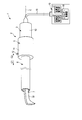
- FIG. 1 is a diagram showing an ultrasonic treatment apparatus 1 of the present embodiment.
- the ultrasonic treatment apparatus 1 includes an ultrasonic treatment tool 2.
- the ultrasonic treatment instrument 2 has a longitudinal axis C.
- One of the directions parallel to the longitudinal axis C is the distal direction (the direction of the arrow C1 in FIG. 1), and the opposite direction to the distal direction is the proximal direction (the direction of the arrow C2 in FIG. 1).
- tip direction and the base end direction be a longitudinal-axis direction.
- the ultrasonic treatment apparatus 1 treats a treatment target such as a living tissue using high-frequency power (high-frequency current) in addition to ultrasonic vibration.
- high-frequency current high-frequency current
- the ultrasonic treatment instrument 2 includes a transducer unit 3, a holding unit 5, a sheath 6, and an ultrasonic probe 7.
- the holding unit 5 includes a cylindrical case portion 11 that extends along the longitudinal axis C.
- An energy operation input button 12 that is an energy operation input unit is attached to the cylindrical case unit 11.
- the vibrator unit 3 includes a vibrator case 13.
- the vibrator unit 3 is connected to the holding unit 5 by inserting the vibrator case 13 into the cylindrical case portion 11 from the proximal direction side.
- One end of a cable 15 is connected to the base end of the vibrator case 13.
- the other end of the cable 15 is connected to a control unit 10 such as an energy source device.
- the control unit 10 includes an ultrasonic power source 16, a high frequency power source 17, and an energy control unit 18.
- the energy control unit 18 is electrically connected to the energy operation input button 12 via an electrical path unit (not shown) extending through the transducer case 13 and the cable 15.
- the energy control unit 18 controls the output state of the ultrasonic power from the ultrasonic power source 16 and the output state of the high frequency power from the high frequency power source 17 based on the input of the energy operation with the energy operation input button 12. Yes.
- the ultrasonic power source 16 and the high frequency power source 17 may be separate bodies or the same power source.
- the energy control unit 18 is formed of, for example, a CPU (Central Processing Unit) or an ASIC (application specific integrated circuit) and a storage unit such as a memory.
- FIG. 2 is a diagram showing a configuration of the vibrator unit 3.
- the transducer unit 3 includes the above-described transducer case 13 and an ultrasonic transducer 21 that is a vibration generating unit provided inside the transducer case 13.
- the ultrasonic transducer 21 includes a plurality (four in this embodiment) of piezoelectric elements 22A to 22D that convert electric current (alternating current) into ultrasonic vibration. For this reason, ultrasonic vibration is generated in the ultrasonic transducer 21 by transmitting ultrasonic power to the ultrasonic transducer 21.
- a horn member 23 extending along the longitudinal axis C is provided inside the vibrator case 13.
- the horn member 23 includes a vibrator mounting portion 25.
- a member for forming the ultrasonic vibrator 21 such as the piezoelectric elements 22A to 22D is attached to the vibrator mounting portion 25.
- the horn member 23 is formed with a cross-sectional area changing portion 26. In the cross-sectional area changing portion 26, the cross-sectional area perpendicular to the longitudinal axis C becomes smaller toward the front end direction.
- the cross-sectional area changing unit 26 increases the amplitude of the ultrasonic vibration.
- a female screw portion 27 is provided at the tip of the horn member 23.
- a male screw portion 28 is provided at the proximal end portion of the ultrasonic probe 7.
- the ultrasonic probe 7 is connected to the distal direction side of the horn member 23.
- the ultrasonic probe 7 extends along the longitudinal axis C.
- the horn member 23 is connected to the ultrasonic probe 7 inside the cylindrical case portion 11.
- the ultrasonic transducer 21 that is a vibration generating unit is located on the proximal direction side of the ultrasonic probe 7.
- the sheath 6 is connected to the holding unit 5 by being inserted into the cylindrical case portion 11 from the distal direction side.
- the sheath 6 is coupled to the transducer case 13 inside the cylindrical case portion 11.
- the ultrasonic probe 7 is inserted through the sheath 6. For this reason, the distal end portion of the ultrasonic probe 7 protrudes from the distal end of the sheath 6 in the distal direction.
- one end of electrical wirings 29 ⁇ / b> A and 29 ⁇ / b> B is connected to the ultrasonic transducer 21.
- the electrical wires 29 ⁇ / b> A and 29 ⁇ / b> B pass through the inside of the cable 15 and the other end is connected to the ultrasonic power source 16 of the control unit 10.
- ultrasonic power is supplied from the ultrasonic power source 16 to the ultrasonic vibrator 21 via the electrical wirings 29 ⁇ / b> A and 29 ⁇ / b> B
- ultrasonic vibration is generated in the ultrasonic vibrator 21.
- the generated ultrasonic vibration is transmitted from the ultrasonic transducer 21 to the ultrasonic probe 7 via the horn member 23.
- FIG. 3 is a diagram showing the ultrasonic probe 7.
- one of the directions perpendicular to the longitudinal axis C is defined as a first vertical direction (the direction of the arrow P1 in FIG. 3), and the direction opposite to the first vertical direction is defined as a second vertical direction (the arrow in FIG. 3).
- P2 direction the direction opposite to the first vertical direction
- one of the first vertical direction and the second vertical direction perpendicular to the longitudinal axis C is defined as a third vertical direction (the direction of the arrow P3 in FIG. 3), and the third vertical direction.
- the direction opposite to is the fourth vertical direction (the direction of the arrow P4 in FIG. 3).
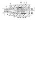
- FIG. 4 is a diagram showing the configuration of the distal end portion of the sheath 6 and the distal end portion of the ultrasonic probe 7.
- the sheath 6 is shown in a cross section perpendicular to the first vertical direction and the second vertical direction, and the ultrasonic probe 7 is shown as viewed from the first vertical direction side.
- 5 is a cross-sectional view taken along line VV in FIG. 4
- FIG. 6 is a cross-sectional view taken along line VI-VI in FIG.
- the ultrasonic probe 7 includes a probe main body 31 extending along the longitudinal axis C.
- the ultrasonic vibration transmitted to the ultrasonic probe 7 is transmitted from the proximal direction to the distal direction in the probe main body 31.
- the ultrasonic probe 7 (probe main body 31) vibrates (longitudinal vibration) with the longitudinal direction parallel to the longitudinal axis C as the vibration direction.
- a predetermined resonance frequency (vibration state) in which the tip of the ultrasonic probe 7 (tip of the probe main body 31) becomes the most distal antinode position A1, which is one of the antinode positions of ultrasonic vibration (longitudinal vibration).
- Vibrate Vibrate.
- the most distal antinode position A1 is located closest to the distal direction among the antinode positions of ultrasonic vibration.
- a position where the dimension from the distal end to the proximal end of the probe main body 31 in the state where the ultrasonic probe 7 vibrates at a predetermined resonance frequency becomes a quarter wavelength of the ultrasonic vibration is defined as a reference position R0.
- the reference position R0 coincides with the most advanced node position N1, which is one of the node positions of ultrasonic vibration (longitudinal vibration) in a state where the ultrasonic probe 7 vibrates at a predetermined resonance frequency.
- the most advanced node position N1 is located on the most distal direction side among the ultrasonic vibration node positions.
- the reference position R0 (the most distal node position N1) is located on the proximal direction side from the distal end of the sheath 6. Therefore, the reference position R0 is located inside the sheath 6.
- a treatment portion 32 is provided at the distal end portion of the probe main body portion 31.
- the ultrasonic probe 7 is inserted into the sheath 6 with the treatment portion 32 protruding from the distal end of the sheath 6 toward the distal direction.
- the treatment section 32 includes a curved projecting portion 33 that curves in the third vertical direction with respect to the longitudinal axis C and projects in the third vertical direction.
- the curved protrusion 33 is formed in a hook shape.
- the curved projecting portion 33 includes a projecting distal end surface 35 facing the distal end direction (the direction of the arrow C1 in FIG. 3) and a projecting proximal end surface 36 facing the proximal end direction (the direction of the arrow C2 in FIG. 3).
- the protruding tip surface 35 forms the tip of the ultrasonic probe 7. Further, the base end position of the curved protrusion 33 is set to a curved base end position B1. The curved proximal end position B1 is located on the distal direction side from the distal end of the sheath 6.
- An insulating layer portion 37 is formed on the outer surface of the probe main body portion 31.
- the insulating layer portion 37 is a coating layer formed from an insulating material such as a resin, for example, and is indicated by dot hatching in FIGS. 3 and 4.
- the insulating layer portion 37 extends from the treatment portion 32 toward the proximal end.
- the entire outer surface of the probe main body 31 is covered by the insulating layer portion 37 in the range between the distal end of the ultrasonic probe 7 and the distal end of the sheath 6 in the longitudinal direction (that is, the treatment portion 32). Covered. Therefore, in the present embodiment, the outer surface of the probe main body 31 is not exposed to the outside even in the treatment section 32 located on the distal direction side from the distal end of the sheath 6.
- the insulating layer portion 37 is extended from the reference position R0 (the most advanced node position N1) to a portion on the proximal direction side. For this reason, the base end of the insulating layer portion 37 is located on the base end direction side from the reference position R0, and is located on the base end direction side from the tip end of the sheath 6. Therefore, the base end of the insulating layer portion 37 is located inside the sheath 6.
- the insulating layer portion 37 is in close contact with the outer surface of the probe main body portion 31. For this reason, when the probe main body 31 transmits ultrasonic vibration, the insulating layer 37 vibrates integrally with the probe main body 31 (longitudinal vibration).
- the outer surface of the insulating layer portion 37 includes a first conductive coating portion 38A that is a first electrode portion and a second conductive coating portion 38B that is a second electrode portion.
- the first conductive coating portion 38A and the second conductive coating portion 38B are formed of a resin containing silver powder, metal plating, or the like, and have conductivity.
- the first conductive coating portion 38A and the second conductive coating portion 38B are shown by solid line hatching.
- One end of a first electric wiring portion 39A that is a first electric path portion is connected to the first conductive coating portion 38A.
- a second electric wiring portion 39B which is a second electric path portion, is connected to the second conductive coating portion 38B.
- the first electric wiring portion 39A and the second electric wiring portion 39B extend through the inside of the sheath 6, the inside of the vibrator case 13, and the inside of the cable 15.
- the other end of the first electric wiring portion 39A and the other end of the second electric wiring portion 39B are connected to the high frequency power source 17 of the control unit 10.
- the first electric wiring portion 39A and the second electric wiring portion 39B are electrically insulated from each other and electrically insulated from the probe main body portion 31 and the horn member 23.
- High frequency power is transmitted from the high frequency power source 17 to the first conductive coating portion 38A through the first electric wiring portion 39A.
- the first conductive coating portion 38A functions as an electrode (first electrode portion).
- High frequency power is transmitted from the high frequency power source 17 to the second conductive coating portion 38B through the second electrical wiring portion 39B.
- the second conductive coating portion 38B functions as an electrode (second electrode portion) different from the first conductive coating portion 38A.
- the first conductive coating part 38A and the second conductive coating part 38B function as electrodes, the first conductive coating part 38A has a different potential from the second conductive coating part 38B.
- the insulating layer portion 37 includes a first insulating surface portion 41A whose outer surface faces the first vertical direction, and a second insulating surface portion 41B whose outer surface faces the second vertical direction.
- the first conductive coating portion 38A is provided on the first insulating surface portion 41A
- the second conductive coating portion 38B is provided on the second insulating surface portion 41B.
- An insulating layer portion 37 (first insulating surface portion 41A) is provided between the first conductive coating portion 38A and the probe main body portion 31, and between the second conductive coating portion 38B and the probe main body portion 31. Is provided with an insulating layer portion 37 (second insulating surface portion 41B). For this reason, the first conductive coating portion 38 ⁇ / b> A and the second conductive coating portion 38 ⁇ / b> B are electrically insulated from the probe main body portion 31.
- the first conductive coating portion 38A and the second conductive coating portion 38B are provided on the outer surface of the insulating layer portion 37. Further, the first conductive coating portion 38A is located away from the second conductive coating portion 38B in the direction around the longitudinal axis. Therefore, the first conductive coating portion 38A and the second conductive coating portion 38B are electrically insulated by the insulating layer portion 37.
- the first conductive coating portion 38A is in close contact with the outer surface of the insulating layer portion 37 in the first insulating surface portion 41A. For this reason, when the probe main body 31 transmits ultrasonic vibration, the first conductive coating portion 38 ⁇ / b> A vibrates integrally with the probe main body 31 and the insulating layer portion 37 (longitudinal vibration). Further, the second conductive coating portion 38B is in close contact with the outer surface of the insulating layer portion 37 in the second insulating surface portion 41B. For this reason, when the probe main body 31 transmits ultrasonic vibration, the second conductive coating portion 38B vibrates integrally with the probe main body portion 31, the insulating layer portion 37, and the first conductive coating portion 38A (longitudinal vibration). )
- the first conductive coating portion 38A extends from the curved protruding portion 33 toward the proximal end in the first insulating surface portion 41A. Further, the second conductive coating portion 38B extends from the curved protrusion 33 toward the proximal direction in the second insulating surface portion 41B. The first conductive coating portion 38A and the second conductive coating portion 38B extend toward the proximal direction at least up to the reference position R0 (the most distal node position N1). The base end of the first conductive coating portion 38A and the base end of the second conductive coating portion 38B are located on the base end direction side from the reference position R0 or the reference position R0.
- the proximal end of the first conductive coating portion 38 ⁇ / b> A and the proximal end of the second conductive coating portion 38 ⁇ / b> B are located on the proximal direction side from the distal end of the sheath 6 and are located inside the sheath 6.
- the base end of the first conductive coating portion 38 ⁇ / b> A and the base end of the second conductive coating portion 38 ⁇ / b> B are located on the distal direction side from the base end of the insulating layer portion 37. Therefore, the first conductive coating portion 38A does not contact the probe main body portion 31 in any part.
- the second conductive coating portion 38B does not contact the probe main body portion 31 in any part.
- first electric wiring portion 39A is connected to the first conductive coating portion 38A at the reference position R0 (or in the vicinity of the reference position R0).
- second electric wiring portion 39B is connected to the second conductive coating portion 38B at the reference position R0 (or in the vicinity of the reference position R0). Since the reference position R0 is the most advanced node position N1 in a state where the ultrasonic probe 7 vibrates at a predetermined resonance frequency, the amplitude of ultrasonic vibration (longitudinal vibration) becomes zero. In the vicinity of the reference position R0, the amplitude of the ultrasonic vibration becomes small.
- the first electric wiring portion 39A is firmly connected to the first conductive coating portion 38A. Then, the second electric wiring portion 39B is firmly connected to the second conductive coating portion 38B.
- the ultrasonic probe 7 includes a first insulating coating portion 42A that covers the outer surface of the first conductive coating portion 38A, and a second insulating coating portion 42B that covers the outer surface of the second conductive coating portion 38B. .
- the first insulating coating portion 42A and the second insulating coating portion 42B are formed of an insulating material such as a resin, and are indicated by broken line hatching in FIGS.
- the distal end of the first insulating coating portion 42A is located on the proximal direction side from the curved proximal end position B1. For this reason, in the curved protrusion 33, the first conductive coating portion 38A is exposed to the outside, and the first conductive exposed portion 43A is formed.
- the distal end of the second insulating coating portion 42B is located on the proximal direction side with respect to the curved proximal end position B1. Therefore, in the curved protrusion 33, the second conductive coating portion 38B is exposed to the outside, and the second conductive exposed portion 43B is formed. In a state where a treatment target such as a living tissue is brought into contact with the protruding proximal end surface 36 of the curved protruding portion 33, the treatment target is in contact with the first conductive exposed portion 43A and the second conductive exposed portion 43B.
- the distal end of the first insulating coating portion 42A and the distal end of the second insulating coating portion 42B are located on the distal direction side from the distal end of the sheath 6. Further, the proximal end of the first insulating coating portion 42 ⁇ / b> A and the proximal end of the second insulating coating portion 42 ⁇ / b> B are located on the proximal direction side from the distal end of the sheath 6. For this reason, the first conductive coating portion 38A is not exposed to the outside at a portion other than the first conductive exposed portion 43A.
- first conductive exposed portion 43A first conductive exposed portion 43A
- second conductive coating portion 38B is not exposed to the outside at portions other than the second conductive exposed portion 43B. That is, in the treatment portion 32 located on the distal direction side from the distal end of the sheath 6, a part of the second conductive coating portion 38B (second conductive exposed portion 43B) is exposed to the outside.
- a living tissue or the like that is different from the treatment target does not contact the first conductive coating portion (first electrode portion) 38A at a portion other than the first conductive exposed portion 43A, and other than the second conductive exposed portion 43B.
- the second conductive coating portion (second electrode portion) 38B is not in contact with the portion.
- the base end of the first insulating coating portion 42A and the base end of the second insulating coating portion 42B are located on the distal direction side from the reference position R0 (the most distal node position N). For this reason, the outer surface of the first conductive coating portion 38A is not covered with the first insulating coating portion 42A at the reference position R0 where the first electric wiring portion 39A is connected to the first conductive coating portion 38A. . For this reason, the high frequency power is reliably transmitted from the first electric wiring portion 39A to the first conductive coating portion 38A.
- the outer surface of the second conductive coating portion 38B is not covered by the second insulating coating portion 42B. . For this reason, the high frequency power is reliably transmitted from the second electric wiring portion 39B to the second conductive coating portion 38B.
- the ultrasonic probe 7 and the ultrasonic treatment apparatus 1 of the present embodiment When treating a treatment target such as a biological tissue (blood vessel) using the ultrasonic treatment apparatus 1, the ultrasonic probe 7 and the sheath 6 are inserted into the body cavity. Then, the treatment target is brought into contact with the protruding proximal end surface 36 of the curved protruding portion 33 of the treatment portion 32. As a result, the first conductive exposed portion 43A of the first conductive coating portion (first electrode portion) 38A and the second conductive exposed portion 43B of the second conductive coating portion (second electrode portion) 38B are Contact the treatment target. In this state, an energy operation is input with the energy operation input button 12. Thereby, the ultrasonic power is output from the ultrasonic power source 16 and the high frequency power is output from the high frequency power source 17 by the energy control unit 18.
- a treatment target such as a biological tissue (blood vessel)
- the ultrasonic probe 7 and the sheath 6 are inserted into the body cavity. Then, the treatment
- ultrasonic vibration is generated in the ultrasonic vibrator 21.
- the generated ultrasonic vibration is transmitted to the ultrasonic probe 7 via the horn member 23.
- ultrasonic vibration is transmitted from the proximal direction to the distal direction to the treatment portion 32, and the probe main body portion 31 vibrates (longitudinal vibration) at a predetermined resonance frequency.
- the insulating layer portion 37, the first conductive coating portion (first electrode portion) 38A, and the second conductive coating portion (second electrode portion) 38B vibrate integrally with the probe main body portion 31.
- the first conductive coating portion 38A functions as an electrode (first electrode portion).
- the second conductive coating portion 38B functions as an electrode (second electrode portion) different from the first conductive coating portion 38A.
- the first conductive coating portion 38A has a different potential from the second conductive coating portion 38B.
- the treatment target 32 vibrates (longitudinal vibration) in a state where the treatment target is in contact with the protruding proximal end surface 36 of the curved protrusion 33, the treatment target is incised. Further, since the treatment target is in contact with the first conductive exposed portion 43A and the second conductive exposed portion 43B, the treatment target is passed between the first conductive coating portion 38A and the second conductive coating portion 38B. A high-frequency current flows, and a bipolar treatment is performed using the first conductive coating portion 38A and the second conductive coating portion 38B as electrodes. When the high frequency current flows through the treatment target, the treatment target is denatured and solidified. As described above, coagulation (sealing) is performed simultaneously with the incision (cutting) of the treatment target.
- the first conductive coating portion 38A and the second conductive coating portion 38B vibrate integrally with the probe main body portion 31. Therefore, even in the bipolar treatment in which the treatment object contacts the first conductive coating part (first electrode part) 38A and the second conductive coating part (second electrode part) 38B, the first conductive exposure of the treatment object. The sticking to the part 43A and the sticking to the second conductive exposed part 43B to be treated are effectively prevented. Thereby, treatment performance can be appropriately ensured in treatment using ultrasonic vibration and high-frequency power.
- the base end of the first conductive coating portion 38A and the base end of the second conductive coating portion 38B are located on the tip direction side from the base end of the insulating layer portion 37. Accordingly, the first conductive coating part 38A does not contact the probe main body part 31 at any part, and the second conductive coating part 38B does not contact the probe main body part 31 at any part. For this reason, in the bipolar treatment using high-frequency power, between the first conductive coating portion (first electrode portion) 38A and the second conductive coating portion (second electrode portion) 38B, other than the treatment target It is effectively prevented that a high frequency current flows through the portion (for example, the probe main body 31). Thereby, in the bipolar treatment, the current density of the high-frequency current flowing through the treatment target is increased, and the treatment performance can be improved.
- first electric wiring portion 39A is connected to the first conductive coating portion 38A at the reference position R0 (the most distal node position N1), and one end of the second electric wiring portion 39B is connected to the reference position R0. It is connected to the second conductive coating portion 38B at (the most advanced node position N1). Therefore, even when the first conductive coating portion 38A and the second conductive coating portion 38B are vibrated integrally with the probe main body portion 31, the first electric wiring portion 39A is firmly connected to the first conductive coating portion 38A. Then, the second electric wiring portion 39B is firmly connected to the second conductive coating portion 38B. Therefore, high frequency power can be appropriately transmitted from the first electrical wiring portion 39A to the first conductive coating portion 38A, and high frequency power can be appropriately transmitted from the second electrical wiring portion 39B to the second conductive coating portion 38B. Can communicate.
- first conductive coating portion 38A is not exposed to the outside by the first insulating coating portion 42A at a portion other than the first conductive exposed portion 43A.
- second conductive coating portion 38B is not exposed to the outside by the second insulating coating portion 42B except for the second conductive exposed portion 43B. Therefore, in a bipolar treatment using a high-frequency current, a living tissue or the like that is different from the treatment target does not contact the first conductive coating portion (first electrode portion) 38A at a portion other than the first conductive exposed portion 43A.
- the second conductive coating portion (second electrode portion) 38B is not in contact with the portion other than the second conductive exposed portion 43B. Thereby, in bipolar treatment, treatment performance can be improved.
- the outer surface of the first conductive coating portion 38A is not covered with the first insulating coating portion 42A.
- the outer surface of the second conductive coating portion 38B is not covered by the second insulating coating portion 42B. .
- high frequency power can be reliably transmitted from the first electrical wiring portion 39A to the first conductive coating portion 38A, and high frequency power can be reliably transmitted from the second electrical wiring portion 39B to the second conductive coating portion 38B. Can be transmitted.
- the two conductive coating portions (38A, 38B) functioning as electrodes are provided, but the present invention is not limited to this.
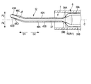
- FIGS. 7 to 10 as a first modification, only one conductive coating portion 38 may be provided.
- FIG. 7 is a diagram showing the distal end portion of the ultrasonic probe 7
- FIG. 8 is a diagram showing the distal end portion of the ultrasonic probe 7 and the distal end portion of the sheath 6.
- 9 is a cross-sectional view taken along line IX-IX in FIG. 8
- FIG. 10 is a cross-sectional view taken along line XX in FIG.
- FIG. 7 is a diagram showing the distal end portion of the ultrasonic probe 7
- FIG. 8 is a diagram showing the distal end portion of the ultrasonic probe 7 and the distal end portion of the sheath 6.
- 9 is a cross-sectional view taken along line IX-IX in FIG. 8
- FIG. 10 is a cross-sectional view taken along line XX
- the sheath 6 is shown in a cross section perpendicular to the first vertical direction and the second vertical direction, and the ultrasonic probe 7 is shown as viewed from the first vertical direction side. 7 and 8, the insulating layer portion 37 is indicated by hatching with dots, and the conductive coating portion 38 is indicated by hatching with solid lines.
- the conductive coating portion 38 has substantially the same configuration as the first conductive coating portion 38A of the first embodiment, and is a first electrode portion that functions as an electrode when high-frequency power is transmitted. In other words, the conductive coating portion 38 vibrates integrally with the probe main body portion 31 (longitudinal vibration). In addition, the conductive coating portion 38 is formed on the outer surface of the insulating layer portion 37.
- the insulating layer portion 37 is extended to a portion on the proximal direction side from the reference position R0 (the most distal node position N1), and the conductive coating portion 38 is extended toward at least the reference position R0 in the proximal direction. Has been. Further, the base end of the conductive coating portion 38 is located inside the sheath 6 and is located on the distal direction side from the base end of the insulating layer portion 37.
- one end of the electric wiring portion 39 that is an electric path portion is connected to the conductive coating portion 38.
- the electrical wiring portion 39 has a configuration substantially similar to that of the first electrical wiring portion 39A of the first embodiment. That is, the other end of the electrical wiring portion 39 is connected to the high frequency power source 17 of the control unit 10. Then, high-frequency power is transmitted from the high-frequency power source 17 to the conductive coating unit 38 via the electrical wiring unit 39.
- the insulating coating part 42 has substantially the same configuration as the first insulating coating part 42A of the first embodiment. That is, the distal end of the insulating coating portion 42 is located on the proximal direction side from the curved base end position B1, and the conductive projection portion 38 is exposed to the outside in the curved protrusion 33, and the conductive exposed portion 43 is formed. Yes. When a treatment target is brought into contact with the protruding proximal end surface 36 of the curved protrusion 33, the treatment target contacts the conductive exposed portion 43.
- the distal end of the insulating coating portion 42 is located on the distal direction side from the distal end of the sheath 6, and the proximal end of the insulating coating portion 42 is located inside the sheath 6.
- the base end of the insulating coating part 42 is located in the front end direction side from the reference position R0 (the most distal node position N). 7 and 8, the insulating coating portion 42 is indicated by broken line hatching.
- the present modification unlike the first embodiment, in the range between the distal end of the ultrasonic probe 7 and the distal end of the sheath 6 in the longitudinal direction (that is, the treatment portion 32), Only a part, not the entire surface, is covered with the insulating layer portion 37.
- the outer surface of the probe main body 31 is exposed to the outside at a part of the protruding proximal end surface 36 of the curved protruding portion 33. That is, a main body exposed portion 45 that is exposed to the outside at the protruding proximal end surface 36 of the treatment portion 32 is provided on the outer surface of the probe main body portion 31.
- the main body exposed portion 45 is not covered with the insulating layer portion 37.
- the main body exposed part 45 is indicated by solid line hatching.
- one end of an electrical wiring (not shown) is connected to the proximal end portion of the horn member 23.
- the electrical wiring extends through the inside of the cable 15 and the other end is connected to the high-frequency power source 17.
- High frequency power is transmitted to the main body exposed portion 45 from the high frequency power source 17 through electrical wiring (not shown), the horn member 23 and the probe main body portion 31.
- the main body exposed portion 45 functions as an electrode (second electrode portion) different from the conductive coating portion (first electrode portion) 38.
- the main body exposed portion 45 is located away from the conductive coating portion 38. Further, an insulating layer portion 37 is provided between the conductive coating portion 38 and the probe main body portion 31, and the conductive coating portion 38 is electrically insulated from the probe main body portion 31. For this reason, the conductive coating portion (first electrode portion) 38 and the main body exposed portion (second electrode portion) 45 are electrically insulated by the insulating layer portion 37. Further, since the main body exposed portion 45 is a part of the probe main body portion 31, it vibrates integrally with the probe main body portion 31 (longitudinal vibration).
- the treatment target is incised when the treatment portion 32 vibrates (longitudinal vibration) while the treatment target is in contact with the protruding proximal end surface 36 of the curved protrusion 33.
- the treatment target comes into contact with the conductive exposed portion 43 and the main body exposed portion 45 of the conductive coating portion 38. Therefore, a high-frequency current flows through the treatment target between the conductive coating portion 38 and the main body exposed portion 45, and a bipolar treatment is performed using the conductive coating portion 38 and the main body exposed portion 45 as electrodes.
- the treatment target is coagulated. As described above, coagulation (sealing) is performed simultaneously with the incision (cutting) of the treatment target.
- the conductive coating portion 38 and the main body exposed portion 45 vibrate integrally with the probe main body portion 31. Therefore, even in the bipolar treatment in which the treatment target is in contact with the conductive coating portion (first electrode portion) 38 and the main body exposed portion (second electrode portion) 45, the sticking to the conductive exposure portion 43 of the treatment target, and Sticking to the main body exposed portion 45 to be treated is effectively prevented. Thereby, treatment performance can be appropriately ensured in treatment using ultrasonic vibration and high-frequency power. In addition, this modification also has the same effect as that described in the first embodiment.
- the hook-shaped curved protrusion 33 may not be provided in the treatment portion 32.
- the treatment portion 32 is formed in a spatula shape.
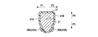
- the first vertical direction (the direction of arrow P1 in FIG. 11), the second vertical direction (the direction of arrow P2 in FIG. 11), and the third vertical direction ( The direction of the arrow P3 in FIG. 11) and the fourth vertical direction (the direction of the arrow P4 in FIG. 11) are defined.
- the treatment portion 32 includes a curved extending portion 47 that is curved with respect to the longitudinal axis C in the third vertical direction and the fourth vertical direction.
- the tip of the ultrasonic probe 7 is formed by the curved extending portion 47.
- the dimensions in the first vertical direction and the second vertical direction are larger than the dimensions in the third vertical direction and the fourth vertical direction.
- the entire outer surface of the probe main body 31 is in the range between the distal end of the ultrasonic probe 7 and the distal end of the sheath 6 (that is, the treatment portion 32) in the longitudinal axis direction. Is covered with an insulating layer portion 37.
- the insulating layer portion 37 extends from the reference position R0 (the most distal node position N1) to a portion on the proximal direction side.
- the insulating layer portion 37 includes a first insulating surface portion 48A having an outer surface facing the first vertical direction, a second insulating surface portion 48B having an outer surface facing the second vertical direction, and a third outer surface having a third surface.
- a third insulating surface portion 48C facing in the vertical direction and a fourth insulating surface portion 48D having an outer surface facing in the fourth vertical direction are provided.
- the first conductive coating portion 38A that is the first electrode portion is provided on the first insulating surface portion 48A
- the second electrode portion that is the second electrode portion is provided on the second insulating surface portion 48B.
- the conductive coating portion 38B is provided.
- the first insulating coating portion 42A is exposed to the outside of the first conductive coating portion 38A in a state in which the first conductive exposed portion 43A of the first conductive coating portion 38A is exposed to the outside in the curved extending portion 47. It covers the surface.
- the second conductive coating portion 38B of the second conductive coating portion 38B is exposed to the outside
- the second insulating coating portion 42B is exposed to the outside of the second conductive coating portion 38B. It covers the surface.
- a first electrode portion is provided on the third insulating surface portion 48C.
- the conductive coating portion 38A may be extended, and the second conductive coating portion 38B as the second electrode portion may be extended on the fourth insulating surface portion 48D.
- the second and third modified examples are electrically connected between the first conductive coating portion 38A and the second conductive coating portion 38B by the insulating layer portion 37. Insulated.
- the second modification and the third modification also have the same effects as those of the first embodiment. 11 to 13, the insulating layer portion 37 is indicated by dot hatching, the first conductive coating portion 38A and the second conductive coating portion 38B are indicated by solid line hatching, and the first insulating coating portion is shown. 42A and the second insulating coating portion 42B are indicated by dashed hatching.
- the insulating layer portion (for example, 37) is formed on the outer surface of the probe main body portion (for example, 31) from the treatment portion (for example, 32) toward the proximal direction (for example, C2). Yes. And the 1st electrode part (for example, 38A; 38) is provided in the outer surface of the insulating layer part (for example, 37) in the state which at least one part exposes with respect to the exterior in the treatment part (for example, 32). . And the 2nd electrode part (for example, 38B; 45) is provided in the state which at least one part exposes with respect to the exterior in a treatment part (for example, 32).
- the first electrode portion (for example, 38A; 38) and the second electrode portion (for example, 38B; 45) function as electrodes to which high-frequency power is transmitted, and the first electrode portion is formed by the insulating layer portion (for example, 37).
- 38A; 38) and the second electrode portion (for example, 38B; 45) are electrically insulated.
- the probe main body (for example, 31) transmits ultrasonic vibration
- the probe main body (for example, 31) has an insulating layer (for example, 37), a first electrode (for example, 38A; 38), and a second electrode. It vibrates integrally with the part (for example, 38B; 45).
Landscapes
- Health & Medical Sciences (AREA)
- Surgery (AREA)
- Engineering & Computer Science (AREA)
- Life Sciences & Earth Sciences (AREA)
- Biomedical Technology (AREA)
- Public Health (AREA)
- Nuclear Medicine, Radiotherapy & Molecular Imaging (AREA)
- Veterinary Medicine (AREA)
- General Health & Medical Sciences (AREA)
- Heart & Thoracic Surgery (AREA)
- Medical Informatics (AREA)
- Molecular Biology (AREA)
- Animal Behavior & Ethology (AREA)
- Physics & Mathematics (AREA)
- Otolaryngology (AREA)
- Plasma & Fusion (AREA)
- Dentistry (AREA)
- Mechanical Engineering (AREA)
- Surgical Instruments (AREA)
Abstract
Description
本発明の第1の実施形態について、図1乃至図6を参照して説明する。
なお、第1の実施形態では、電極として機能する2つの導電コーティング部(38A,38B)が設けられているが、これに限るものではない。例えば、第1の変形例として図7乃至図10に示すように、導電コーティング部38が1つのみ、設けられてもよい。ここで、図7は、超音波プローブ7の先端部を示す図であり、図8は、超音波プローブ7の先端部及びシース6の先端部を示す図である。そして、図9は、図8のIX―IX線断面図であり、図10は、図8のX―X線断面図である。なお、図8では、シース6は第1の垂直方向及び第2の垂直方向に垂直な断面で示され、超音波プローブ7は、第1の垂直方向側から視た状態で示されている。また、図7及び図8では、絶縁層部37はドットのハッチングで示され、導電コーティング部38は実線のハッチングで示されている。
Claims (17)
- 長手軸に沿って延設され、基端方向から先端方向へ超音波振動を伝達するプローブ本体部と、
前記プローブ本体部の先端部に設けられる処置部と、
前記プローブ本体部の外表面において前記処置部から前記基端方向へ向かって形成され、前記プローブ本体部が前記超音波振動を伝達することにより、前記プローブ本体部と一体に振動する絶縁層部と、
少なくとも一部が前記処置部において外部に対して露出する状態で前記絶縁層部の外表面に設けられ、高周波電力が伝達される電極として機能するとともに、前記プローブ本体部が前記超音波振動を伝達することにより、前記プローブ本体部及び前記絶縁層部と一体に振動する第1の電極部と、
少なくとも一部が前記処置部において前記外部に対して露出する状態で設けられ、前記高周波電力が伝達される前記第1の電極部とは別の電極として機能するとともに、前記絶縁層部によって前記第1の電極部との間が電気的に絶縁され、前記プローブ本体部が前記超音波振動を伝達することにより、前記プローブ本体部、前記絶縁層部及び前記第1の電極部と一体に振動する第2の電極部と、
を具備する超音波プローブ。 - 前記プローブ本体部の先端から前記基端方向への寸法が前記超音波振動の4分の1波長となる位置を基準位置とした場合に、前記絶縁層部は、前記基準位置より基端方向側の部位まで延設され、
前記第1の電極部の基端は、前記絶縁層部の基端より先端方向側に位置している、
請求項1の超音波プローブ。 - 前記処置部において前記第1の電極部の一部が前記外部に対して露出する状態に、前記第1の電極部の外表面を覆う絶縁コーティング部をさらに具備する、請求項2の超音波プローブ。
- 前記第1の電極部は、少なくとも前記基準位置まで前記基端方向に向かって延設され、
前記絶縁コーティング部の基端は、前記基準位置より前記先端方向側に位置している、
請求項3の超音波プローブ。 - 請求項4の超音波プローブと、
前記基準位置で前記第1の電極部に一端が接続される電気経路部と、
前記電気経路部の他端が接続され、前記第1の電極部及び前記第2の電極部に伝達される前記高周波電力を発生するとともに、前記電気経路部を介して前記第1の電極部に前記高周波電力を伝達する高周波電力源と、
を具備する超音波処置装置。 - 請求項4の超音波プローブと、
前記処置部が前記先端方向へ向かって突出する状態で前記超音波プローブが挿通され、前記絶縁コーティング部の前記基端が内部に位置するシースと、
を具備する超音波処置装置。 - 請求項2の超音波プローブと、
前記処置部が前記先端方向へ向かって突出する状態で前記超音波プローブが挿通され、前記絶縁層部の前記基端が内部に位置するシースと、
を具備する超音波処置装置。 - 前記第2の電極部は、前記絶縁層部の外表面に設けられている、請求項1の超音波プローブ。
- 前記プローブ本体部の先端から前記基端方向への寸法が前記超音波振動の4分の1波長となる位置を基準位置とした場合に、前記絶縁層部は、前記基準位置より基端方向側の部位まで延設され、
前記第1の電極部の基端及び前記第2の電極部の基端は、前記絶縁層部の基端より先端方向側に位置している、
請求項8の超音波プローブ。 - 前記処置部において前記第1の電極部の一部が前記外部に対して露出する状態に、前記第1の電極部の外表面を覆う第1の絶縁コーティング部と、
前記処置部において前記第2の電極部の一部が前記外部に対して露出する状態に、前記第2の電極部の外表面を覆う第2の絶縁コーティング部と、
をさらに具備する、請求項9の超音波プローブ。 - 前記第1の電極部及び前記第2の電極部は、少なくとも前記基準位置まで前記基端方向に向かって延設され、
前記第1の絶縁コーティング部の基端及び前記第2の絶縁コーティング部の基端は、前記基準位置より前記先端方向側に位置している、
請求項10の超音波プローブ。 - 請求項11の超音波プローブと、
前記基準位置で前記第1の電極部に一端が接続される第1の電気経路部と、
前記基準位置で前記第2の電極部に一端が接続される第2の電気経路部と、
前記第1の電気経路部の他端及び前記第2の電気経路部の他端が接続され、前記第1の電極部及び前記第2の電極部に伝達される前記高周波電力を発生するとともに、前記第1の電気経路部を介して前記第1の電極部に前記高周波電力を伝達し、前記第2の電気経路部を介して前記第2の電極部に前記高周波電力を伝達する高周波電力源と、
を具備する超音波処置装置。 - 請求項11の超音波プローブと、
前記処置部が前記先端方向へ向かって突出する状態で前記超音波プローブが挿通され、前記第1の絶縁コーティング部の前記基端及び前記第2の絶縁コーティング部の基端が内部に位置するシースと、
を具備する超音波処置装置。 - 前記長手軸に垂直な方向の1つを第1の垂直方向とし、前記第1の垂直方向とは反対方向を第2の垂直方向とした場合に、前記絶縁層部は、前記外表面が前記第1の垂直方向を向く第1の絶縁表面部と、前記外表面が前記第2の垂直方向を向く第2の絶縁表面部と、を備え、
前記第1の電極部は、前記第1の絶縁表面部に設けられ、
前記第2の電極部は、前記第2の絶縁表面部に設けられている、
請求項8の超音波プローブ。 - 前記長手軸に垂直で、かつ、前記第1の垂直方向及び前記第2の垂直方向に垂直な方向の一方を第3の垂直方向とした場合に、前記処置部は、前記長手軸に対して前記第3の垂直方向に湾曲し、前記第3の垂直方向に向かって突出する湾曲突出部を備え、
前記第1の電極部は、前記第1の絶縁表面部において前記湾曲突出部から前記基端方向へ向かって延設され、
前記第2の電極部は、前記第2の絶縁表面部において前記湾曲突出部から前記基端方向へ向かって延設されている、
請求項14の超音波プローブ。 - 前記第2の電極部は、前記処置部において前記外部に対して露出する状態で前記プローブ本体部の前記外表面に形成され、前記プローブ本体部を介して前記高周波電力が伝達されている、請求項1の超音波プローブ。
- 請求項1の超音波プローブと、
前記超音波プローブより基端方向側に設けられ、前記処置部に伝達される前記超音波振動を発生する振動発生部と、
前記振動発生部に伝達される超音波電力を発生する超音波電力源と、
前記第1の電極部及び前記第2の電極部に伝達される前記高周波電力を発生する高周波電力源と、
を具備する超音波処置装置。
Priority Applications (4)
| Application Number | Priority Date | Filing Date | Title |
|---|---|---|---|
| EP14881589.7A EP3103407B1 (en) | 2014-02-06 | 2014-11-28 | Ultrasonic probe and ultrasonic treatment apparatus |
| CN201480058233.5A CN105658161B (zh) | 2014-02-06 | 2014-11-28 | 超声波探头及超声波处理装置 |
| JP2015527381A JP5836543B1 (ja) | 2014-02-06 | 2014-11-28 | 超音波プローブ及び超音波処置装置 |
| US15/053,768 US9592072B2 (en) | 2014-02-06 | 2016-02-25 | Ultrasonic treatment apparatus |
Applications Claiming Priority (2)
| Application Number | Priority Date | Filing Date | Title |
|---|---|---|---|
| JP2014-021672 | 2014-02-06 | ||
| JP2014021672 | 2014-02-06 |
Related Child Applications (1)
| Application Number | Title | Priority Date | Filing Date |
|---|---|---|---|
| US15/053,768 Continuation US9592072B2 (en) | 2014-02-06 | 2016-02-25 | Ultrasonic treatment apparatus |
Publications (1)
| Publication Number | Publication Date |
|---|---|
| WO2015118757A1 true WO2015118757A1 (ja) | 2015-08-13 |
Family
ID=53777574
Family Applications (1)
| Application Number | Title | Priority Date | Filing Date |
|---|---|---|---|
| PCT/JP2014/081594 WO2015118757A1 (ja) | 2014-02-06 | 2014-11-28 | 超音波プローブ及び超音波処置装置 |
Country Status (5)
| Country | Link |
|---|---|
| US (1) | US9592072B2 (ja) |
| EP (1) | EP3103407B1 (ja) |
| JP (1) | JP5836543B1 (ja) |
| CN (1) | CN105658161B (ja) |
| WO (1) | WO2015118757A1 (ja) |
Cited By (4)
| Publication number | Priority date | Publication date | Assignee | Title |
|---|---|---|---|---|
| CN105832405A (zh) * | 2015-10-28 | 2016-08-10 | 安进医疗科技(北京)有限公司 | 用于外科手术的手柄及手术控制系统 |
| WO2018087837A1 (ja) * | 2016-11-09 | 2018-05-17 | オリンパス株式会社 | 医療機器、医療機器の製造方法 |
| WO2018087838A1 (ja) * | 2016-11-09 | 2018-05-17 | オリンパス株式会社 | 医療機器 |
| CN108697451A (zh) * | 2016-01-20 | 2018-10-23 | 奥林巴斯株式会社 | 处置器具 |
Families Citing this family (118)
| Publication number | Priority date | Publication date | Assignee | Title |
|---|---|---|---|---|
| US10835307B2 (en) | 2001-06-12 | 2020-11-17 | Ethicon Llc | Modular battery powered handheld surgical instrument containing elongated multi-layered shaft |
| US8182501B2 (en) | 2004-02-27 | 2012-05-22 | Ethicon Endo-Surgery, Inc. | Ultrasonic surgical shears and method for sealing a blood vessel using same |
| PL1802245T3 (pl) | 2004-10-08 | 2017-01-31 | Ethicon Endosurgery Llc | Ultradźwiękowy przyrząd chirurgiczny |
| US20070191713A1 (en) | 2005-10-14 | 2007-08-16 | Eichmann Stephen E | Ultrasonic device for cutting and coagulating |
| US7621930B2 (en) | 2006-01-20 | 2009-11-24 | Ethicon Endo-Surgery, Inc. | Ultrasound medical instrument having a medical ultrasonic blade |
| US8142461B2 (en) | 2007-03-22 | 2012-03-27 | Ethicon Endo-Surgery, Inc. | Surgical instruments |
| US8057498B2 (en) | 2007-11-30 | 2011-11-15 | Ethicon Endo-Surgery, Inc. | Ultrasonic surgical instrument blades |
| US8911460B2 (en) | 2007-03-22 | 2014-12-16 | Ethicon Endo-Surgery, Inc. | Ultrasonic surgical instruments |
| US8808319B2 (en) | 2007-07-27 | 2014-08-19 | Ethicon Endo-Surgery, Inc. | Surgical instruments |
| US8523889B2 (en) | 2007-07-27 | 2013-09-03 | Ethicon Endo-Surgery, Inc. | Ultrasonic end effectors with increased active length |
| US9044261B2 (en) | 2007-07-31 | 2015-06-02 | Ethicon Endo-Surgery, Inc. | Temperature controlled ultrasonic surgical instruments |
| US8430898B2 (en) | 2007-07-31 | 2013-04-30 | Ethicon Endo-Surgery, Inc. | Ultrasonic surgical instruments |
| US8512365B2 (en) | 2007-07-31 | 2013-08-20 | Ethicon Endo-Surgery, Inc. | Surgical instruments |
| US8623027B2 (en) | 2007-10-05 | 2014-01-07 | Ethicon Endo-Surgery, Inc. | Ergonomic surgical instruments |
| US10010339B2 (en) | 2007-11-30 | 2018-07-03 | Ethicon Llc | Ultrasonic surgical blades |
| US9089360B2 (en) | 2008-08-06 | 2015-07-28 | Ethicon Endo-Surgery, Inc. | Devices and techniques for cutting and coagulating tissue |
| US9700339B2 (en) | 2009-05-20 | 2017-07-11 | Ethicon Endo-Surgery, Inc. | Coupling arrangements and methods for attaching tools to ultrasonic surgical instruments |
| US8663220B2 (en) | 2009-07-15 | 2014-03-04 | Ethicon Endo-Surgery, Inc. | Ultrasonic surgical instruments |
| USRE47996E1 (en) | 2009-10-09 | 2020-05-19 | Ethicon Llc | Surgical generator for ultrasonic and electrosurgical devices |
| US9039695B2 (en) | 2009-10-09 | 2015-05-26 | Ethicon Endo-Surgery, Inc. | Surgical generator for ultrasonic and electrosurgical devices |
| US11090104B2 (en) | 2009-10-09 | 2021-08-17 | Cilag Gmbh International | Surgical generator for ultrasonic and electrosurgical devices |
| US10441345B2 (en) | 2009-10-09 | 2019-10-15 | Ethicon Llc | Surgical generator for ultrasonic and electrosurgical devices |
| US8961547B2 (en) | 2010-02-11 | 2015-02-24 | Ethicon Endo-Surgery, Inc. | Ultrasonic surgical instruments with moving cutting implement |
| US8951272B2 (en) | 2010-02-11 | 2015-02-10 | Ethicon Endo-Surgery, Inc. | Seal arrangements for ultrasonically powered surgical instruments |
| US8486096B2 (en) | 2010-02-11 | 2013-07-16 | Ethicon Endo-Surgery, Inc. | Dual purpose surgical instrument for cutting and coagulating tissue |
| US8469981B2 (en) | 2010-02-11 | 2013-06-25 | Ethicon Endo-Surgery, Inc. | Rotatable cutting implement arrangements for ultrasonic surgical instruments |
| US8795327B2 (en) | 2010-07-22 | 2014-08-05 | Ethicon Endo-Surgery, Inc. | Electrosurgical instrument with separate closure and cutting members |
| US9192431B2 (en) | 2010-07-23 | 2015-11-24 | Ethicon Endo-Surgery, Inc. | Electrosurgical cutting and sealing instrument |
| US9259265B2 (en) | 2011-07-22 | 2016-02-16 | Ethicon Endo-Surgery, Llc | Surgical instruments for tensioning tissue |
| WO2013119545A1 (en) | 2012-02-10 | 2013-08-15 | Ethicon-Endo Surgery, Inc. | Robotically controlled surgical instrument |
| US9439668B2 (en) | 2012-04-09 | 2016-09-13 | Ethicon Endo-Surgery, Llc | Switch arrangements for ultrasonic surgical instruments |
| US20140005705A1 (en) | 2012-06-29 | 2014-01-02 | Ethicon Endo-Surgery, Inc. | Surgical instruments with articulating shafts |
| US9393037B2 (en) | 2012-06-29 | 2016-07-19 | Ethicon Endo-Surgery, Llc | Surgical instruments with articulating shafts |
| US20140005702A1 (en) | 2012-06-29 | 2014-01-02 | Ethicon Endo-Surgery, Inc. | Ultrasonic surgical instruments with distally positioned transducers |
| US9820768B2 (en) | 2012-06-29 | 2017-11-21 | Ethicon Llc | Ultrasonic surgical instruments with control mechanisms |
| US9198714B2 (en) | 2012-06-29 | 2015-12-01 | Ethicon Endo-Surgery, Inc. | Haptic feedback devices for surgical robot |
| US9408622B2 (en) | 2012-06-29 | 2016-08-09 | Ethicon Endo-Surgery, Llc | Surgical instruments with articulating shafts |
| US9351754B2 (en) | 2012-06-29 | 2016-05-31 | Ethicon Endo-Surgery, Llc | Ultrasonic surgical instruments with distally positioned jaw assemblies |
| US9226767B2 (en) | 2012-06-29 | 2016-01-05 | Ethicon Endo-Surgery, Inc. | Closed feedback control for electrosurgical device |
| US9326788B2 (en) | 2012-06-29 | 2016-05-03 | Ethicon Endo-Surgery, Llc | Lockout mechanism for use with robotic electrosurgical device |
| EP2900158B1 (en) | 2012-09-28 | 2020-04-15 | Ethicon LLC | Multi-function bi-polar forceps |
| US9095367B2 (en) | 2012-10-22 | 2015-08-04 | Ethicon Endo-Surgery, Inc. | Flexible harmonic waveguides/blades for surgical instruments |
| US20140135804A1 (en) | 2012-11-15 | 2014-05-15 | Ethicon Endo-Surgery, Inc. | Ultrasonic and electrosurgical devices |
| US10226273B2 (en) | 2013-03-14 | 2019-03-12 | Ethicon Llc | Mechanical fasteners for use with surgical energy devices |
| US9241728B2 (en) | 2013-03-15 | 2016-01-26 | Ethicon Endo-Surgery, Inc. | Surgical instrument with multiple clamping mechanisms |
| US9814514B2 (en) | 2013-09-13 | 2017-11-14 | Ethicon Llc | Electrosurgical (RF) medical instruments for cutting and coagulating tissue |
| EP3050529A4 (en) * | 2013-09-27 | 2017-05-17 | Olympus Corporation | Ultrasonic probe, ultrasonic treatment tool and treatment system |
| US9265926B2 (en) | 2013-11-08 | 2016-02-23 | Ethicon Endo-Surgery, Llc | Electrosurgical devices |
| GB2521229A (en) | 2013-12-16 | 2015-06-17 | Ethicon Endo Surgery Inc | Medical device |
| GB2521228A (en) | 2013-12-16 | 2015-06-17 | Ethicon Endo Surgery Inc | Medical device |
| US9795436B2 (en) | 2014-01-07 | 2017-10-24 | Ethicon Llc | Harvesting energy from a surgical generator |
| US9554854B2 (en) | 2014-03-18 | 2017-01-31 | Ethicon Endo-Surgery, Llc | Detecting short circuits in electrosurgical medical devices |
| US10463421B2 (en) | 2014-03-27 | 2019-11-05 | Ethicon Llc | Two stage trigger, clamp and cut bipolar vessel sealer |
| US10092310B2 (en) | 2014-03-27 | 2018-10-09 | Ethicon Llc | Electrosurgical devices |
| US9737355B2 (en) | 2014-03-31 | 2017-08-22 | Ethicon Llc | Controlling impedance rise in electrosurgical medical devices |
| US9913680B2 (en) | 2014-04-15 | 2018-03-13 | Ethicon Llc | Software algorithms for electrosurgical instruments |
| JP5959769B2 (ja) * | 2014-05-23 | 2016-08-02 | オリンパス株式会社 | 処置具 |
| WO2016013338A1 (ja) * | 2014-07-24 | 2016-01-28 | オリンパス株式会社 | 超音波処置システム、エネルギー源ユニット、及び、エネルギー源ユニットの作動方法 |
| US10285724B2 (en) | 2014-07-31 | 2019-05-14 | Ethicon Llc | Actuation mechanisms and load adjustment assemblies for surgical instruments |
| US10639092B2 (en) | 2014-12-08 | 2020-05-05 | Ethicon Llc | Electrode configurations for surgical instruments |
| US10245095B2 (en) | 2015-02-06 | 2019-04-02 | Ethicon Llc | Electrosurgical instrument with rotation and articulation mechanisms |
| US10321950B2 (en) | 2015-03-17 | 2019-06-18 | Ethicon Llc | Managing tissue treatment |
| US10342602B2 (en) | 2015-03-17 | 2019-07-09 | Ethicon Llc | Managing tissue treatment |
| US10595929B2 (en) | 2015-03-24 | 2020-03-24 | Ethicon Llc | Surgical instruments with firing system overload protection mechanisms |
| US10034684B2 (en) | 2015-06-15 | 2018-07-31 | Ethicon Llc | Apparatus and method for dissecting and coagulating tissue |
| US11020140B2 (en) | 2015-06-17 | 2021-06-01 | Cilag Gmbh International | Ultrasonic surgical blade for use with ultrasonic surgical instruments |
| US10357303B2 (en) | 2015-06-30 | 2019-07-23 | Ethicon Llc | Translatable outer tube for sealing using shielded lap chole dissector |
| US10034704B2 (en) | 2015-06-30 | 2018-07-31 | Ethicon Llc | Surgical instrument with user adaptable algorithms |
| US11129669B2 (en) | 2015-06-30 | 2021-09-28 | Cilag Gmbh International | Surgical system with user adaptable techniques based on tissue type |
| US11141213B2 (en) | 2015-06-30 | 2021-10-12 | Cilag Gmbh International | Surgical instrument with user adaptable techniques |
| US11051873B2 (en) | 2015-06-30 | 2021-07-06 | Cilag Gmbh International | Surgical system with user adaptable techniques employing multiple energy modalities based on tissue parameters |
| US10898256B2 (en) | 2015-06-30 | 2021-01-26 | Ethicon Llc | Surgical system with user adaptable techniques based on tissue impedance |
| US10154852B2 (en) | 2015-07-01 | 2018-12-18 | Ethicon Llc | Ultrasonic surgical blade with improved cutting and coagulation features |
| US11058475B2 (en) | 2015-09-30 | 2021-07-13 | Cilag Gmbh International | Method and apparatus for selecting operations of a surgical instrument based on user intention |
| US10595930B2 (en) | 2015-10-16 | 2020-03-24 | Ethicon Llc | Electrode wiping surgical device |
| US10179022B2 (en) | 2015-12-30 | 2019-01-15 | Ethicon Llc | Jaw position impedance limiter for electrosurgical instrument |
| US10575892B2 (en) | 2015-12-31 | 2020-03-03 | Ethicon Llc | Adapter for electrical surgical instruments |
| US11229471B2 (en) | 2016-01-15 | 2022-01-25 | Cilag Gmbh International | Modular battery powered handheld surgical instrument with selective application of energy based on tissue characterization |
| US10716615B2 (en) | 2016-01-15 | 2020-07-21 | Ethicon Llc | Modular battery powered handheld surgical instrument with curved end effectors having asymmetric engagement between jaw and blade |
| US11129670B2 (en) | 2016-01-15 | 2021-09-28 | Cilag Gmbh International | Modular battery powered handheld surgical instrument with selective application of energy based on button displacement, intensity, or local tissue characterization |
| US10299821B2 (en) | 2016-01-15 | 2019-05-28 | Ethicon Llc | Modular battery powered handheld surgical instrument with motor control limit profile |
| JP6250246B1 (ja) * | 2016-01-29 | 2017-12-20 | オリンパス株式会社 | 高周波処置具 |
| US10555769B2 (en) | 2016-02-22 | 2020-02-11 | Ethicon Llc | Flexible circuits for electrosurgical instrument |
| US10485607B2 (en) | 2016-04-29 | 2019-11-26 | Ethicon Llc | Jaw structure with distal closure for electrosurgical instruments |
| US10646269B2 (en) | 2016-04-29 | 2020-05-12 | Ethicon Llc | Non-linear jaw gap for electrosurgical instruments |
| US10702329B2 (en) | 2016-04-29 | 2020-07-07 | Ethicon Llc | Jaw structure with distal post for electrosurgical instruments |
| US10456193B2 (en) | 2016-05-03 | 2019-10-29 | Ethicon Llc | Medical device with a bilateral jaw configuration for nerve stimulation |
| US10245064B2 (en) | 2016-07-12 | 2019-04-02 | Ethicon Llc | Ultrasonic surgical instrument with piezoelectric central lumen transducer |
| US10893883B2 (en) | 2016-07-13 | 2021-01-19 | Ethicon Llc | Ultrasonic assembly for use with ultrasonic surgical instruments |
| US10842522B2 (en) | 2016-07-15 | 2020-11-24 | Ethicon Llc | Ultrasonic surgical instruments having offset blades |
| US10376305B2 (en) | 2016-08-05 | 2019-08-13 | Ethicon Llc | Methods and systems for advanced harmonic energy |
| US10285723B2 (en) | 2016-08-09 | 2019-05-14 | Ethicon Llc | Ultrasonic surgical blade with improved heel portion |
| USD847990S1 (en) | 2016-08-16 | 2019-05-07 | Ethicon Llc | Surgical instrument |
| US10952759B2 (en) | 2016-08-25 | 2021-03-23 | Ethicon Llc | Tissue loading of a surgical instrument |
| US10736649B2 (en) | 2016-08-25 | 2020-08-11 | Ethicon Llc | Electrical and thermal connections for ultrasonic transducer |
| US10603064B2 (en) | 2016-11-28 | 2020-03-31 | Ethicon Llc | Ultrasonic transducer |
| US11266430B2 (en) | 2016-11-29 | 2022-03-08 | Cilag Gmbh International | End effector control and calibration |
| US10820920B2 (en) | 2017-07-05 | 2020-11-03 | Ethicon Llc | Reusable ultrasonic medical devices and methods of their use |
| US11607265B2 (en) * | 2018-08-24 | 2023-03-21 | Covidien Lp | Cutting electrode enhancement for laparoscopic electrosurgical device |
| EP3698734A1 (en) * | 2019-02-21 | 2020-08-26 | Orthofix S.R.L. | System and method for driving an ultrasonic device |
| US11911063B2 (en) | 2019-12-30 | 2024-02-27 | Cilag Gmbh International | Techniques for detecting ultrasonic blade to electrode contact and reducing power to ultrasonic blade |
| US11696776B2 (en) | 2019-12-30 | 2023-07-11 | Cilag Gmbh International | Articulatable surgical instrument |
| US11950797B2 (en) | 2019-12-30 | 2024-04-09 | Cilag Gmbh International | Deflectable electrode with higher distal bias relative to proximal bias |
| US11684412B2 (en) | 2019-12-30 | 2023-06-27 | Cilag Gmbh International | Surgical instrument with rotatable and articulatable surgical end effector |
| US11452525B2 (en) | 2019-12-30 | 2022-09-27 | Cilag Gmbh International | Surgical instrument comprising an adjustment system |
| US11937866B2 (en) | 2019-12-30 | 2024-03-26 | Cilag Gmbh International | Method for an electrosurgical procedure |
| US11786291B2 (en) | 2019-12-30 | 2023-10-17 | Cilag Gmbh International | Deflectable support of RF energy electrode with respect to opposing ultrasonic blade |
| US11812957B2 (en) | 2019-12-30 | 2023-11-14 | Cilag Gmbh International | Surgical instrument comprising a signal interference resolution system |
| US11779387B2 (en) | 2019-12-30 | 2023-10-10 | Cilag Gmbh International | Clamp arm jaw to minimize tissue sticking and improve tissue control |
| US11986201B2 (en) | 2019-12-30 | 2024-05-21 | Cilag Gmbh International | Method for operating a surgical instrument |
| US11944366B2 (en) | 2019-12-30 | 2024-04-02 | Cilag Gmbh International | Asymmetric segmented ultrasonic support pad for cooperative engagement with a movable RF electrode |
| US11779329B2 (en) | 2019-12-30 | 2023-10-10 | Cilag Gmbh International | Surgical instrument comprising a flex circuit including a sensor system |
| US11723716B2 (en) | 2019-12-30 | 2023-08-15 | Cilag Gmbh International | Electrosurgical instrument with variable control mechanisms |
| US11937863B2 (en) | 2019-12-30 | 2024-03-26 | Cilag Gmbh International | Deflectable electrode with variable compression bias along the length of the deflectable electrode |
| US20210196362A1 (en) | 2019-12-30 | 2021-07-01 | Ethicon Llc | Electrosurgical end effectors with thermally insulative and thermally conductive portions |
| US11660089B2 (en) | 2019-12-30 | 2023-05-30 | Cilag Gmbh International | Surgical instrument comprising a sensing system |
| US11786294B2 (en) | 2019-12-30 | 2023-10-17 | Cilag Gmbh International | Control program for modular combination energy device |
| WO2023223166A1 (en) * | 2022-05-16 | 2023-11-23 | Covidien Lp | Combination ultrasonic and plasma instrument |
Citations (4)
| Publication number | Priority date | Publication date | Assignee | Title |
|---|---|---|---|---|
| JPS62211057A (ja) * | 1986-03-12 | 1987-09-17 | オリンパス光学工業株式会社 | 超音波振動処置装置 |
| JPH04221539A (ja) * | 1990-03-19 | 1992-08-12 | Everest Medical Corp | 内側乳房動脈を採取するためのバイポーラ外科用メス |
| JP2001087274A (ja) * | 1999-09-24 | 2001-04-03 | Olympus Optical Co Ltd | 超音波処置具 |
| JP2013504396A (ja) * | 2009-09-15 | 2013-02-07 | セロン アクチエンゲゼルシャフト メディカル インスツルメンツ | 超音波およびhf複合型手術用システム |
Family Cites Families (11)
| Publication number | Priority date | Publication date | Assignee | Title |
|---|---|---|---|---|
| US4043342A (en) * | 1974-08-28 | 1977-08-23 | Valleylab, Inc. | Electrosurgical devices having sesquipolar electrode structures incorporated therein |
| EP0148250A1 (en) * | 1983-07-06 | 1985-07-17 | STASZ, Peter | Electro cautery surgical blade |
| JPH11318919A (ja) * | 1998-05-11 | 1999-11-24 | Olympus Optical Co Ltd | 手術装置及び手術システム |
| US20030073987A1 (en) * | 2001-10-16 | 2003-04-17 | Olympus Optical Co., Ltd. | Treating apparatus and treating device for treating living-body tissue |
| US7223267B2 (en) * | 2004-02-06 | 2007-05-29 | Misonix, Incorporated | Ultrasonic probe with detachable slidable cauterization forceps |
| US8357154B2 (en) * | 2004-07-20 | 2013-01-22 | Microline Surgical, Inc. | Multielectrode electrosurgical instrument |
| JP4679416B2 (ja) | 2006-04-10 | 2011-04-27 | オリンパス株式会社 | 手術装置 |
| US20080058803A1 (en) * | 2006-08-30 | 2008-03-06 | Kenichi Kimura | Surgical instrument and surgical instrument driving method |
| JP5430161B2 (ja) * | 2008-06-19 | 2014-02-26 | オリンパスメディカルシステムズ株式会社 | 超音波手術装置 |
| US20100168741A1 (en) * | 2008-12-29 | 2010-07-01 | Hideo Sanai | Surgical operation apparatus |
| US20100331742A1 (en) * | 2009-06-26 | 2010-12-30 | Shinya Masuda | Surgical operating apparatus |
-
2014
- 2014-11-28 CN CN201480058233.5A patent/CN105658161B/zh active Active
- 2014-11-28 JP JP2015527381A patent/JP5836543B1/ja active Active
- 2014-11-28 WO PCT/JP2014/081594 patent/WO2015118757A1/ja active Application Filing
- 2014-11-28 EP EP14881589.7A patent/EP3103407B1/en active Active
-
2016
- 2016-02-25 US US15/053,768 patent/US9592072B2/en active Active
Patent Citations (4)
| Publication number | Priority date | Publication date | Assignee | Title |
|---|---|---|---|---|
| JPS62211057A (ja) * | 1986-03-12 | 1987-09-17 | オリンパス光学工業株式会社 | 超音波振動処置装置 |
| JPH04221539A (ja) * | 1990-03-19 | 1992-08-12 | Everest Medical Corp | 内側乳房動脈を採取するためのバイポーラ外科用メス |
| JP2001087274A (ja) * | 1999-09-24 | 2001-04-03 | Olympus Optical Co Ltd | 超音波処置具 |
| JP2013504396A (ja) * | 2009-09-15 | 2013-02-07 | セロン アクチエンゲゼルシャフト メディカル インスツルメンツ | 超音波およびhf複合型手術用システム |
Non-Patent Citations (1)
| Title |
|---|
| See also references of EP3103407A4 * |
Cited By (7)
| Publication number | Priority date | Publication date | Assignee | Title |
|---|---|---|---|---|
| CN105832405A (zh) * | 2015-10-28 | 2016-08-10 | 安进医疗科技(北京)有限公司 | 用于外科手术的手柄及手术控制系统 |
| CN108697451A (zh) * | 2016-01-20 | 2018-10-23 | 奥林巴斯株式会社 | 处置器具 |
| EP3406215A4 (en) * | 2016-01-20 | 2019-09-25 | Olympus Corporation | TREATMENT TOOL |
| CN108697451B (zh) * | 2016-01-20 | 2021-05-18 | 奥林巴斯株式会社 | 处置器具 |
| US11071581B2 (en) | 2016-01-20 | 2021-07-27 | Olympus Corporation | Treatment instrument including a resin coating |
| WO2018087837A1 (ja) * | 2016-11-09 | 2018-05-17 | オリンパス株式会社 | 医療機器、医療機器の製造方法 |
| WO2018087838A1 (ja) * | 2016-11-09 | 2018-05-17 | オリンパス株式会社 | 医療機器 |
Also Published As
| Publication number | Publication date |
|---|---|
| US20160175000A1 (en) | 2016-06-23 |
| JPWO2015118757A1 (ja) | 2017-03-23 |
| JP5836543B1 (ja) | 2015-12-24 |
| EP3103407B1 (en) | 2018-11-21 |
| CN105658161A (zh) | 2016-06-08 |
| CN105658161B (zh) | 2018-05-22 |
| US9592072B2 (en) | 2017-03-14 |
| EP3103407A4 (en) | 2017-10-25 |
| EP3103407A1 (en) | 2016-12-14 |
Similar Documents
| Publication | Publication Date | Title |
|---|---|---|
| JP5836543B1 (ja) | 超音波プローブ及び超音波処置装置 | |
| US9693793B2 (en) | Ultrasonic probe and ultrasonic treatment instrument | |
| EP2859858B1 (en) | Ultrasound probe | |
| US20170224405A1 (en) | Grasping treatment unit and grasping treatment instrument | |
| WO2015137139A1 (ja) | 把持ユニット及びバイポーラ処置具 | |
| JP5959769B2 (ja) | 処置具 | |
| JP5379931B1 (ja) | 把持処置装置 | |
| JPWO2016009921A1 (ja) | 処置具 | |
| US10010342B2 (en) | Ultrasonic probe and ultrasonic treatment apparatus | |
| CN107205764B (zh) | 振动体单元以及超声波探头 | |
| CN107708585A (zh) | 医疗器械 | |
| JP6192886B1 (ja) | 振動伝達部材、超音波処置具及び振動体ユニット | |
| US20150196782A1 (en) | Ultrasonic probe and ultrasonic treatment device | |
| WO2018070043A1 (ja) | 超音波トランスデューサ | |
| JP5970142B2 (ja) | 超音波プローブ及び超音波処置具 | |
| WO2019167194A1 (ja) | 超音波プローブ及び超音波処置具 | |
| WO2018087841A1 (ja) | 振動伝達部材及び超音波処置具 | |
| US10010365B2 (en) | Surgical treatment instrument |
Legal Events
| Date | Code | Title | Description |
|---|---|---|---|
| ENP | Entry into the national phase |
Ref document number: 2015527381 Country of ref document: JP Kind code of ref document: A |
|
| 121 | Ep: the epo has been informed by wipo that ep was designated in this application |
Ref document number: 14881589 Country of ref document: EP Kind code of ref document: A1 |
|
| NENP | Non-entry into the national phase |
Ref country code: DE |
|
| REEP | Request for entry into the european phase |
Ref document number: 2014881589 Country of ref document: EP |
|
| WWE | Wipo information: entry into national phase |
Ref document number: 2014881589 Country of ref document: EP |