WO2015115439A1 - 生体組織切断装置およびその用途 - Google Patents
生体組織切断装置およびその用途 Download PDFInfo
- Publication number
- WO2015115439A1 WO2015115439A1 PCT/JP2015/052225 JP2015052225W WO2015115439A1 WO 2015115439 A1 WO2015115439 A1 WO 2015115439A1 JP 2015052225 W JP2015052225 W JP 2015052225W WO 2015115439 A1 WO2015115439 A1 WO 2015115439A1
- Authority
- WO
- WIPO (PCT)
- Prior art keywords
- cutting
- tissue
- stage
- cut surface
- biological tissue
- Prior art date
Links
- 238000005520 cutting process Methods 0.000 title claims abstract description 658
- 210000001519 tissue Anatomy 0.000 claims description 283
- 238000000034 method Methods 0.000 claims description 42
- 239000012472 biological sample Substances 0.000 claims description 29
- 238000004519 manufacturing process Methods 0.000 claims description 15
- 210000000845 cartilage Anatomy 0.000 claims description 7
- 239000005556 hormone Substances 0.000 claims description 2
- 229940088597 hormone Drugs 0.000 claims description 2
- 210000005228 liver tissue Anatomy 0.000 claims description 2
- 210000004379 membrane Anatomy 0.000 claims description 2
- 210000003205 muscle Anatomy 0.000 claims description 2
- 210000002435 tendon Anatomy 0.000 claims description 2
- 210000000944 nerve tissue Anatomy 0.000 claims 1
- 210000003491 skin Anatomy 0.000 claims 1
- 230000002792 vascular Effects 0.000 claims 1
- 230000001172 regenerating effect Effects 0.000 description 14
- 239000003814 drug Substances 0.000 description 12
- 239000010410 layer Substances 0.000 description 12
- 210000004027 cell Anatomy 0.000 description 9
- 230000008569 process Effects 0.000 description 9
- 238000011069 regeneration method Methods 0.000 description 8
- 239000000758 substrate Substances 0.000 description 8
- 230000015572 biosynthetic process Effects 0.000 description 6
- 238000013459 approach Methods 0.000 description 5
- 239000000853 adhesive Substances 0.000 description 4
- 230000001070 adhesive effect Effects 0.000 description 4
- 239000012790 adhesive layer Substances 0.000 description 4
- 230000007246 mechanism Effects 0.000 description 4
- 230000008929 regeneration Effects 0.000 description 4
- 239000002344 surface layer Substances 0.000 description 4
- 238000002360 preparation method Methods 0.000 description 3
- 239000003795 chemical substances by application Substances 0.000 description 2
- 239000000463 material Substances 0.000 description 2
- 235000015097 nutrients Nutrition 0.000 description 2
- 239000000523 sample Substances 0.000 description 2
- 238000000926 separation method Methods 0.000 description 2
- 230000017423 tissue regeneration Effects 0.000 description 2
- IJVRPNIWWODHHA-UHFFFAOYSA-N 2-cyanoprop-2-enoic acid Chemical compound OC(=O)C(=C)C#N IJVRPNIWWODHHA-UHFFFAOYSA-N 0.000 description 1
- 208000006735 Periostitis Diseases 0.000 description 1
- 239000004830 Super Glue Substances 0.000 description 1
- 230000009471 action Effects 0.000 description 1
- 210000004100 adrenal gland Anatomy 0.000 description 1
- 210000004204 blood vessel Anatomy 0.000 description 1
- 210000001124 body fluid Anatomy 0.000 description 1
- 239000010839 body fluid Substances 0.000 description 1
- 210000001612 chondrocyte Anatomy 0.000 description 1
- 210000000078 claw Anatomy 0.000 description 1
- 239000000470 constituent Substances 0.000 description 1
- 238000011109 contamination Methods 0.000 description 1
- 210000004748 cultured cell Anatomy 0.000 description 1
- 238000012258 culturing Methods 0.000 description 1
- 230000002950 deficient Effects 0.000 description 1
- 230000004069 differentiation Effects 0.000 description 1
- 230000000694 effects Effects 0.000 description 1
- 238000000605 extraction Methods 0.000 description 1
- 239000012634 fragment Substances 0.000 description 1
- 239000011521 glass Substances 0.000 description 1
- 238000000338 in vitro Methods 0.000 description 1
- 238000001727 in vivo Methods 0.000 description 1
- 208000015181 infectious disease Diseases 0.000 description 1
- 210000004400 mucous membrane Anatomy 0.000 description 1
- 210000005036 nerve Anatomy 0.000 description 1
- 210000002379 periodontal ligament Anatomy 0.000 description 1
- 210000003460 periosteum Anatomy 0.000 description 1
- 239000002504 physiological saline solution Substances 0.000 description 1
- 229920000515 polycarbonate Polymers 0.000 description 1
- 239000004417 polycarbonate Substances 0.000 description 1
- 229920000642 polymer Polymers 0.000 description 1
- 230000035755 proliferation Effects 0.000 description 1
- 210000002307 prostate Anatomy 0.000 description 1
- 230000008439 repair process Effects 0.000 description 1
- 230000000717 retained effect Effects 0.000 description 1
- 239000000243 solution Substances 0.000 description 1
- 239000002904 solvent Substances 0.000 description 1
- 210000000130 stem cell Anatomy 0.000 description 1
- 230000004083 survival effect Effects 0.000 description 1
- 210000001258 synovial membrane Anatomy 0.000 description 1
- 210000001685 thyroid gland Anatomy 0.000 description 1
- 238000002054 transplantation Methods 0.000 description 1
Images


Classifications
-
- C—CHEMISTRY; METALLURGY
- C12—BIOCHEMISTRY; BEER; SPIRITS; WINE; VINEGAR; MICROBIOLOGY; ENZYMOLOGY; MUTATION OR GENETIC ENGINEERING
- C12M—APPARATUS FOR ENZYMOLOGY OR MICROBIOLOGY; APPARATUS FOR CULTURING MICROORGANISMS FOR PRODUCING BIOMASS, FOR GROWING CELLS OR FOR OBTAINING FERMENTATION OR METABOLIC PRODUCTS, i.e. BIOREACTORS OR FERMENTERS
- C12M21/00—Bioreactors or fermenters specially adapted for specific uses
- C12M21/08—Bioreactors or fermenters specially adapted for specific uses for producing artificial tissue or for ex-vivo cultivation of tissue
-
- G—PHYSICS
- G01—MEASURING; TESTING
- G01N—INVESTIGATING OR ANALYSING MATERIALS BY DETERMINING THEIR CHEMICAL OR PHYSICAL PROPERTIES
- G01N1/00—Sampling; Preparing specimens for investigation
- G01N1/28—Preparing specimens for investigation including physical details of (bio-)chemical methods covered elsewhere, e.g. G01N33/50, C12Q
- G01N1/286—Preparing specimens for investigation including physical details of (bio-)chemical methods covered elsewhere, e.g. G01N33/50, C12Q involving mechanical work, e.g. chopping, disintegrating, compacting, homogenising
-
- A—HUMAN NECESSITIES
- A61—MEDICAL OR VETERINARY SCIENCE; HYGIENE
- A61B—DIAGNOSIS; SURGERY; IDENTIFICATION
- A61B17/00—Surgical instruments, devices or methods, e.g. tourniquets
- A61B17/32—Surgical cutting instruments
-
- A—HUMAN NECESSITIES
- A61—MEDICAL OR VETERINARY SCIENCE; HYGIENE
- A61B—DIAGNOSIS; SURGERY; IDENTIFICATION
- A61B17/00—Surgical instruments, devices or methods, e.g. tourniquets
- A61B17/32—Surgical cutting instruments
- A61B17/3209—Incision instruments
-
- A—HUMAN NECESSITIES
- A61—MEDICAL OR VETERINARY SCIENCE; HYGIENE
- A61P—SPECIFIC THERAPEUTIC ACTIVITY OF CHEMICAL COMPOUNDS OR MEDICINAL PREPARATIONS
- A61P43/00—Drugs for specific purposes, not provided for in groups A61P1/00-A61P41/00
-
- C—CHEMISTRY; METALLURGY
- C12—BIOCHEMISTRY; BEER; SPIRITS; WINE; VINEGAR; MICROBIOLOGY; ENZYMOLOGY; MUTATION OR GENETIC ENGINEERING
- C12M—APPARATUS FOR ENZYMOLOGY OR MICROBIOLOGY; APPARATUS FOR CULTURING MICROORGANISMS FOR PRODUCING BIOMASS, FOR GROWING CELLS OR FOR OBTAINING FERMENTATION OR METABOLIC PRODUCTS, i.e. BIOREACTORS OR FERMENTERS
- C12M45/00—Means for pre-treatment of biological substances
- C12M45/02—Means for pre-treatment of biological substances by mechanical forces; Stirring; Trituration; Comminuting
-
- G—PHYSICS
- G01—MEASURING; TESTING
- G01N—INVESTIGATING OR ANALYSING MATERIALS BY DETERMINING THEIR CHEMICAL OR PHYSICAL PROPERTIES
- G01N1/00—Sampling; Preparing specimens for investigation
- G01N1/02—Devices for withdrawing samples
- G01N1/04—Devices for withdrawing samples in the solid state, e.g. by cutting
- G01N1/06—Devices for withdrawing samples in the solid state, e.g. by cutting providing a thin slice, e.g. microtome
-
- G—PHYSICS
- G01—MEASURING; TESTING
- G01N—INVESTIGATING OR ANALYSING MATERIALS BY DETERMINING THEIR CHEMICAL OR PHYSICAL PROPERTIES
- G01N1/00—Sampling; Preparing specimens for investigation
- G01N1/28—Preparing specimens for investigation including physical details of (bio-)chemical methods covered elsewhere, e.g. G01N33/50, C12Q
- G01N1/30—Staining; Impregnating ; Fixation; Dehydration; Multistep processes for preparing samples of tissue, cell or nucleic acid material and the like for analysis
-
- G—PHYSICS
- G01—MEASURING; TESTING
- G01N—INVESTIGATING OR ANALYSING MATERIALS BY DETERMINING THEIR CHEMICAL OR PHYSICAL PROPERTIES
- G01N1/00—Sampling; Preparing specimens for investigation
- G01N1/28—Preparing specimens for investigation including physical details of (bio-)chemical methods covered elsewhere, e.g. G01N33/50, C12Q
- G01N1/286—Preparing specimens for investigation including physical details of (bio-)chemical methods covered elsewhere, e.g. G01N33/50, C12Q involving mechanical work, e.g. chopping, disintegrating, compacting, homogenising
- G01N2001/2873—Cutting or cleaving
Definitions
- the present invention relates to a biological tissue cutting device and a use thereof for cutting a biological tissue to produce a tissue piece.
- regenerative medicine In the medical field, attention to regenerative medicine is extremely high, and research is actively conducted.
- a method is generally used in which cells are collected from a tissue derived from the home or other family, seeded on a regeneration scaffold, cultured, and the obtained cultured cells are used.
- adhesion between the collected cells and the scaffold for regeneration is important, setting of culture conditions and the like is important, and there is a problem that it takes time and effort.
- a new regenerative medicine method that does not require culture has been proposed. Specifically, it is a method of regenerating and repairing a tissue by the proliferation and differentiation ability of the transplanted cell by transplanting a stem cell or a mature cell into a damaged or defective part of a living tissue.
- the survival rate of the transplanted cells in the living body is low, and accordingly, the efficiency of function expression is poor, and the expected regenerative repair effect may not be obtained. Therefore, as a method for solving this problem, transplantation of tissue, which is a functional assembly of cells, is considered.
- cartilage instead of collecting and culturing chondrocytes from cartilage, a method of cutting out a fine tissue piece from cartilage and transplanting it to a living body can be mentioned.
- the cartilage can be taken out from the patient at the surgical operation site, the tissue piece can be cut out from the cartilage and transplanted to the living body of the patient, regenerative medicine in the operating room can be realized.
- this method not only the culture after the operation but also the re-operation after the culture is unnecessary, so that the treatment can be performed at low cost and less burden on the patient and the doctor.
- tissue piece is large, the supply of nutrients to the inside of the transplanted tissue piece is poor, and the tissue piece is not sufficiently engrafted in the living body. For this reason, it is required to produce a large amount of fine and uniform tissue pieces that can supply nutrients to the transplanted tissue pieces.
- tissue fragments that are the source of regeneration from limited living tissues. The technology to cut out is required.
- an object of the present invention is to provide a biological tissue cutting device that can easily and efficiently manufacture a fine tissue piece from a biological tissue.
- the biological tissue cutting device of the present invention is a biological tissue cutting device for cutting a biological tissue to produce a tissue piece, A stage unit having a stage for fixing a living tissue; A first cutting unit that cuts biological tissue on the stage to form a cut surface in a first direction; and A second cutting unit that cuts the biological tissue on the stage to form a cut surface in the second direction and a cut surface in the third direction;
- the cut surface in the second direction is a surface direction intersecting with the cut surface in the first direction
- the cut surface in the third direction is a surface direction intersecting with the cut surface in the first direction and the cut surface in the second direction.
- the biological tissue cutting method of the present invention uses the biological tissue cutting device of the present invention, Fixing a living tissue on a stage; A first cutting step of cutting the living tissue to form a cut surface in a first direction by the first cutting unit; and The second cutting unit has a second cutting step of cutting the living tissue to form a cut surface in the second direction and a cut surface in the third direction,
- the cut surface in the second direction is a surface direction intersecting with the cut surface in the first direction
- the cut surface in the third direction is a surface direction intersecting with the cut surface in the second direction and the cut surface in the third direction.
- the method for producing a tissue piece of the present invention is characterized in that a living tissue is cut by the cutting method of the present invention.
- the biological tissue regeneration method of the present invention is characterized by using a tissue piece obtained by the production method of the present invention.
- the surgical method of the present invention is characterized by using a tissue piece obtained by the manufacturing method of the present invention.
- the treatment method of the present invention is characterized by using a tissue piece obtained by the production method of the present invention.
- the biological tissue cutting device of the present invention by forming the cut surface in the first direction and forming the cut surface in the second direction and the cut surface in the third direction, it is simple and efficient. Large quantities of fine tissue pieces can be produced.
- FIG. 1 is a perspective view which shows the outline of the cut surface of the biological sample in this invention. It is a top view of the 1st cutting means of the 1st cutting unit (X plane cutting unit) in the embodiment of the present invention.
- A is a perspective view which shows the outline of the 2nd cutting unit (YZ plane cutting unit) in embodiment of this invention,
- B) is a top view of the 2nd cutting means in the said 2nd cutting unit.
- (C) is a top view of the 3rd cutting means in the 2nd cutting unit.
- (A) is a figure which shows the 1st direction which is the cutting direction by a 1st cutting unit
- (B) is the cutting
- (B) is the schematic which shows a state.
- (A) is a figure which shows the 2nd direction and 3rd direction which are the cutting directions by a 2nd cutting unit
- (B) is the figure of the biological tissue.
- the biological tissue cutting device of the present invention is a biological tissue cutting device for producing a tissue piece by cutting a biological tissue, as described above, A stage unit having a stage for fixing a living tissue; A first cutting unit that cuts biological tissue on the stage to form a cut surface in a first direction; and A second cutting unit that cuts the biological tissue on the stage to form a cut surface in the second direction and a cut surface in the third direction;
- the cut surface in the second direction is a surface direction intersecting with the cut surface in the first direction
- the cut surface in the third direction is a surface direction intersecting with the cut surface in the first direction and the cut surface in the second direction.
- the processing by the second cutting unit is performed once. Formation of the cut surface in the second direction and formation of the cut surface in the third direction can be performed, whereby a fine tissue piece can be obtained.
- the third direction cut surface is formed after the biological tissue is cut to form the second direction cut surface by performing different processes, the third direction cut surface is formed. Since the living tissue collapses (disintegrates), it is difficult to cut.
- the biological tissue can be formed with the cut surface in the second direction and the cut surface in the three directions by a single process by the second cutting unit. For example, the above problems can be avoided and the yield can be improved.
- various “means” can be read as, for example, “mechanism”.
- the second cutting unit can form the cut surface in the second direction and the cut surface in the third direction by a single process. For this reason, it can be said that the cut surface in the second direction and the cut surface in the third direction are simultaneously formed by simultaneous cutting, for example.
- “simultaneous” with respect to the cut surface in the second direction and the cut surface in the third direction means, for example, that the process is performed once per the second cutting unit.
- the surface formation itself may be started, for example, completely at the same time, or may be started with a time difference, and this may be appropriately determined depending on, for example, the structure of the second cutting means and the third cutting means as described later. Can be set.
- the cut surface in the first direction, the cut surface in the second direction, and the cut surface in the third direction only have to satisfy the above-described relationship.
- the surface direction of each of the cut surfaces can be defined, for example, as follows with respect to the surface of the stage that fixes the living tissue. That is, the cut surface in the first direction and the cut surface in the second direction of the biological sample are substantially perpendicular to the surface of the stage, respectively, and the cut surface in the first direction and the cut surface in the second direction are The cutting plane is substantially vertical, and the cutting plane in the third direction of the biological sample is substantially parallel to the surface of the stage.
- FIG. 1 shows an outline of a living tissue fixed on a stage.
- the arrow A indicates the upward direction when the biological tissue 60 is fixed on the stage.
- the cut surface in the first direction and the cut surface in the second direction are substantially perpendicular to the surface (not shown) of the stage, and the cut surface in the third direction is substantially parallel.
- the cut surface in the first direction is, for example, a cut surface formed by cutting in the X-axis direction when viewing the biological tissue 60 from above, and is also referred to as an X surface.
- the cut surface in the second direction is, for example, a cut surface formed by cutting the biological tissue 60 from the upper direction and cutting in the Y-axis direction, and is also referred to as a Y surface.
- the cut surface in the third direction is, for example, a cut surface formed by cutting in a direction perpendicular to the Z axis when viewed from the lateral direction (side direction of the biological tissue), and is also referred to as a Z surface.
- the cut surface in the first direction, the cut surface in the second direction, and the cut surface in the third direction need only intersect with each other, and the intersecting angle is, for example, 90 ⁇ 30 degrees, 90 ⁇ 20 degrees, 90 ⁇ 10 degrees, and 90 ⁇ 1 degrees, and substantially orthogonal or orthogonal is preferable.
- the surface direction of each of the cut surfaces is not limited to orthogonal, and the description in this paragraph can be used.
- the biological tissue to be cut is not particularly limited, and examples thereof include biological tissue used for manufacturing the tissue piece.
- the biological tissue to be cut include a biological tissue used for regenerative medicine, a biological tissue used for cell preparation, and the like. Specific examples include, for example, cartilage, skin tissue, blood vessel tissue, liver tissue, periosteum, synovium, mucous membrane, periodontal ligament membrane tissue, thyroid gland, adrenal gland, hormone producing tissue such as prostate, nerve, tendon, fat, Muscle and so on.
- the tissue piece can be referred to as a tissue piece for regenerative medicine, for example.
- the said tissue piece can also be called the tissue piece for cell preparation, for example.
- the shape of the biological tissue immobilized on the stage is not particularly limited, and examples thereof include a sheet shape and a block shape.
- the size of the living tissue is not particularly limited.
- the biological tissue to be immobilized has a lower limit of thickness of, for example, 0.05 mm, 0.5 mm, and 1 mm, an upper limit of thickness of, for example, 3 mm, 5 mm, and 10 mm, and a thickness range of, for example, 0.05 to 10 mm, 0.5 to 5 mm, 0.5 to 3 mm, and 1 to 3 mm, and the lower limit of the area is, for example, 50 mm 2 , 100 mm 2 , and 200 mm 2.
- the upper limit of the area is, for example, 2 , 500 mm 2 , 5,000 mm 2 , 10,000 mm 2 , and the area ranges are, for example, 50 to 10,000 mm 2 , 100 to 5,000 mm 2 , and 200 to 2,500 mm 2 .
- the method for fixing the living tissue to the stage is not particularly limited, and examples thereof include fixing with an adhesive.
- the adhesive is not particularly limited, and is preferably for medical use, for example, an ⁇ -cyanoacrylate adhesive can be exemplified.
- the material of the surface of the stage which fixes the said biological tissue is not restrict
- the stage may be a slide, for example.
- the shape of the tissue piece cut by the first cutting unit and the second cutting unit of the biological tissue cutting device of the present invention is not particularly limited, and is, for example, a legislative body.
- the size of the tissue piece is not particularly limited, and the lower limit of the length of one side is, for example, 0.03 mm, 0.05 mm, 0.1 mm, 0.2 mm, and the upper limit of the length of one side is, for example, The range of the length of one side is, for example, 0.03 to 3 mm, 0.05 to 3 mm, 0.1 to 2 mm, and 0.2 to 1 mm.
- the first cutting unit includes first cutting means for cutting the biological tissue to form a cutting surface in the first direction
- the second cutting unit includes: Second cutting means for cutting the biological tissue to form a cut surface in the second direction, and third cutting means for cutting the biological tissue to form a cut surface in the third direction.
- the second cutting means and the third cutting means may be configured such that, for example, the formed cutting surface in the second direction and the cutting surface in the third direction are maintained at a constant angle. It is integrated.
- the type of cutting means is not particularly limited as long as it can cut a living tissue. Specific examples include blades such as a cutter and a knife. Can be given.
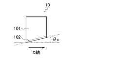
- FIG. 2 is a schematic side view showing an example of the first cutting means 10 in the first cutting unit.
- the first cutting means 10 has a blade 102 formed at the lower end of the main body 101.
- the biological sample is arranged at the tip of the arrow direction and the first cutting means 10 is advanced in the arrow direction, whereby the biological sample is cut by the blade 102, and the first direction A cut surface is formed.
- the blade 102 is preferably inclined at a predetermined angle ⁇ x with respect to the surface. The angle can also be said to be an angle with respect to the moving direction.
- the lower limit is, for example, 1/200, 3/200, or 5/200
- the upper limit is, for example, 30/200, 50/200, or 80/200.
- An angle in which the range is, for example, 1/200 to 80/200, 3/200 to 50/200, 5/200 to 30/200 is preferable.
- the lower limit of the thickness of the blade 102 is, for example, 10 ⁇ m, 20 ⁇ m, and 30 ⁇ m.
- the upper limit is, for example, 500 ⁇ m, 600 ⁇ m, and 850 ⁇ m, and the range is, for example, 10 to 850 ⁇ m, 20 to 600 ⁇ m, and 30 to 30 ⁇ m. 500 ⁇ m.
- FIG. 3A is a perspective view showing an example of the second cutting unit 40
- FIG. 3B is a plan view of the second cutting means 20 of the second cutting unit 40
- FIG. 4 is a plan view of third cutting means 30 of the second cutting unit 40.
- the second cutting unit 40 includes a support body 401, a second cutting means 20, and a third cutting means 30, and the support body 401 has the second cutting means 20 and the third cutting means. 30 is arranged and integrated as a whole.
- the second cutting means 20 has a blade 202 formed at the lower end of the main body 201
- the third cutting means 30 has a blade 302 formed at the end of the main body 301 (the left end in FIG. 3A). Has been.
- each surface direction is a substantially perpendicular direction, for example.
- the second cutting means 20 and the third cutting means 30 are in a relationship in which the respective blades are orthogonal to each other with, for example, an action point as a boundary.
- the blade 202 of the second cutting means 20 is preferably inclined at a predetermined angle ⁇ y with respect to the surface.
- the angle can also be said to be an angle with respect to the moving direction.
- the blade 302 of the third cutting means 30 is preferably moved in a direction parallel to the surface and inclined at a predetermined angle ⁇ z with respect to the moving direction.
- the angle ⁇ y or ⁇ z is expressed by sin ⁇ y or sin ⁇ z
- the lower limit is, for example, 1/200, 3/200, 5/200
- the upper limit is, for example, 30/200, 50/200. 80/200
- an angle in which the range is, for example, 1/200 to 80/200, 3/200 to 50/200, 5/200 to 30/200, is preferable.
- the lower limit of the thickness of the blade 202 of the second cutting means is, for example, 10 ⁇ m, 20 ⁇ m, 30 ⁇ m
- the upper limit is, for example, 500 ⁇ m, 600 ⁇ m, 850 ⁇ m
- the range is, for example, 10-850 ⁇ m, 20-600 ⁇ m, 30 to 500 ⁇ m.
- the lower limit of the thickness of the blade 302 of the third cutting means is, for example, 10 ⁇ m, 20 ⁇ m, or 30 ⁇ m
- the upper limit is, for example, 1500 ⁇ m, 2000 ⁇ m, or 3000 ⁇ m
- the range is, for example, 10 to 3000 ⁇ m, 20 to 20 ⁇ m. 2000 ⁇ m and 30-1500 ⁇ m.
- the blade of the first cutting means and the blade of the second cutting means are, for example, easy to insert into a living tissue and easily maintain the original shape of the living tissue after cutting. It is preferable that it is relatively thin compared to the blade.
- the blade of the first cutting means is relatively thin, for example, compared with the blade of the third cutting means, so that the streaks of the cut surface (for example, the cut shown in FIG. 5A) are more beautiful.
- the second cutting process and the third cutting process are easier to operate.
- the blade of the third cutting means cuts the biological tissue so as to scrape the layers in order from the upper direction to the lower direction so as to form a Z plane, and collects the layers.
- the thickness of the blade of the third cutting means is not particularly limited.
- the blade of the third cutting means is, for example, polished to make it easier to cut, so that the blade is relatively thick compared to the blade of the first cutting means and the blade of the second cutting means. May be.
- a single blade is exemplified as the first cutting means, the second cutting means, and the third cutting means.
- This invention is not limited to this, For example, a double blade may be sufficient.
- the first cutting means may be, for example, a single-edged or double-edged round blade.
- the biological tissue cutting device of the present invention moves the first movement control means for moving the first cutting means in the first cutting unit, the second cutting means and the third cutting means in the second cutting unit. You may provide the 2nd movement control means to make or the stage movement control means to move the stage which fixed the said biological tissue.
- These various control means may be any one type, any two types, or all.
- the various control means is not particularly limited, and examples thereof include means using a ratchet mechanism, means using a cam mechanism, and the like.
- the biological tissue cutting device of the present invention is capable of removing a plurality of tissue pieces from one biological tissue fixed to the stage by repeatedly cutting the biological tissue by the first cutting unit and the second cutting unit. Can be manufactured.
- the repetition of cutting as described above can be controlled by any one of the first movement control means, the second movement control means, and the stage movement control means, or a combination thereof.
- the cutting means may be, for example, manually operated as described later or electrically (automatic), and is not particularly limited depending on the driving method.
- the first cutting unit cuts the biological tissue to form a cut surface in the first direction, and the first cutting unit moves the first cutting unit.
- 1 movement control means In this case, for example, the first movement control unit moves the first cutting unit from the cutting start position of the living tissue to the cutting end position and then moves to a new cutting start position.
- the movement from the cutting start position to the cutting end position means one cutting by moving in one direction with respect to the living tissue (the same applies hereinafter).
- the first cutting means is set at a new cutting start position.
- the first movement control means can subsequently cut the living tissue by moving the first cutting means from the new cutting start position to the cutting end position.
- the first movement control unit may move the first cutting unit from the cutting start position to the cutting end position, and then move the first cutting unit away from the living tissue to the new cutting start position.
- the first cutting means is moved away from the living tissue and moved to a new cutting start position, for example, the cut surface by the first cutting means can be maintained in a cleaner state.
- a method for separating the first cutting means from the living tissue is not particularly limited.
- the first movement control means for example, includes the first cutting means. After moving to the cutting end position, it can be separated from the living tissue by being pushed out from the living tissue.
- the first movement control means for example, the first cutting means After the means is moved to the cutting end position, the means can be separated from the living tissue by being pulled out from the living tissue.
- the first movement control means may move the first cutting means directly from the cutting end position to the new cutting start position. After returning from the cutting end position to the cutting start position, the cutting end position may be moved to the new cutting start position.
- FIGS. 4A and 4B show an outline of a living tissue fixed on a stage.
- the first cutting means is set at the first cutting start position for the living tissue 60 on the stage.
- the biological tissue 60 is viewed from above, and the first cutting in the X-axis direction is performed.
- the first cutting means is moved to the second new cutting start position, and the second cutting in the X-axis direction is performed.
- n-th n is a positive integer
- FIG. 4B By repeating this process up to the n-th (n is a positive integer), as shown in FIG. 4B, a plurality of cuts in the X-axis direction are performed, and a plurality of cut surfaces in the first direction. (X plane) is formed.
- the first cutting unit is also referred to as an “X plane cutting unit”, and the first cutting unit is also referred to as an “X plane cutting unit”.
- the cutting in the X-axis direction can be performed a plurality of times by moving the first cutting means in the X-axis direction, and this series of cutting is preferably set to substantially the same depth.
- the depth is not particularly limited.
- the length of one side of the tissue piece to be finally prepared can be raised, and conditions described below can be used.
- the second cutting unit cuts the biological tissue to form a cut surface in the second direction, and cuts the biological tissue to cut the biological tissue.
- a third cutting means for forming a cutting surface in three directions; a second movement control means for simultaneously moving the second cutting means and the third cutting means; the second cutting means and the third cutting The means is integrated so that the cut surface in the second direction and the cut surface in the third direction to be formed maintain a constant angle.
- the second movement control means for example, simultaneously moves the second cutting means and the third cutting means from the cutting start position of the living tissue to the cutting end position.
- the cutting direction of the blade of the second cutting means is aligned with the surface direction of the cutting surface in the second direction, and the cutting direction of the blade of the third cutting means and the surface of the cutting surface in the third direction are aligned. It is preferable that the direction is aligned. Thereby, for example, if the second cutting means and the third cutting means are moved in a direction parallel to the Y-axis direction and perpendicular to the Z-axis direction, the living tissue is cut. It can cut
- the second movement control means preferably moves the second cutting means and the third cutting means from the cutting start position to the cutting end position and then to a new cutting start position. .
- the second cutting means is set at a new cutting start position.
- the second movement control means can subsequently cut the living tissue by moving the second cutting means from the new cutting start position to the cutting end position.
- the second movement control means moves the second cutting means and the third cutting means from the cutting start position to the cutting end position, and then moves away from the living tissue to start the new cutting. You may move to a position.
- the cutting surface by the second cutting means and the cutting surface by the third cutting means are more It can be kept clean.
- a method for separating the second cutting means from the living tissue is not particularly limited.
- the second movement control means includes, for example, the second cutting means and After moving the third cutting means to the cutting end position, the third cutting means can be separated from the living tissue by pushing out from the living tissue.
- the second movement control means for example, the second cutting means After the means and the third cutting means are moved to the cutting end position, the means and the third cutting means can be separated from the living tissue by being extracted from the living tissue.
- the second movement control unit moves the second cutting unit and the third cutting unit from the cutting start position to the cutting end position, and then completes the cutting along the moving path.
- the position may be moved from the position to the cutting start position, and the second cutting means and the third cutting means may be separated from the living tissue and then moved to the new cutting start position.
- the new cutting is directly performed from the cutting end position. It may be moved to the start position, or after returning from the cutting end position to the cutting start position, it may be moved to the new cutting start position. Then, the living tissue can be cut by moving from the new cutting start position to the cutting end position.
- FIGS. 5A and 5B show an outline of a living tissue fixed on a stage.
- the second cutting means and the third cutting means are set at the first cutting start position with respect to the living tissue 60 on the stage.
- the biological sample 60 is viewed from above, and the first cutting in the Y-axis direction (the direction perpendicular to the Z-axis) is performed.
- the second cutting means and the third cutting means are moved to the first cutting end position, the second cutting means and the third cutting means are moved to the second cutting start position, and Y A second cut in the axial direction is made.
- a plurality of cuts in the Y-axis direction are performed as shown in FIG.
- the cut surface (Y surface) in the second direction and the cut surface (Z surface) in the third direction are formed, the cut surface (X surface) in the first direction, the cut surface in the second direction ( A plurality of tissue pieces formed by the Y plane) and the cut surface (Z plane) in the third direction can be manufactured.
- the second cutting unit is also referred to as “YZ plane cutting unit”
- the second cutting means is also referred to as “Y plane cutting means”.
- the three cutting means is also referred to as “Z plane cutting means”.
- the cut surface in the first direction, the cut surface in the second direction, and the cut surface in the third direction are formed for a predetermined layer.
- the tissue piece in the cut layer is deposited, for example, between the surface of the second cutting unit and the surface of the third cutting unit in the second cutting unit.
- disconnected tissue piece is removed from the biological tissue on the stage, for example, and a new surface is exposed. Therefore, for example, the first cutting means in the first cutting unit, and the second cutting means and the third cutting means in the second cutting unit are set at a position lower than the removed layer, for example. Then, the tissue piece can be continuously manufactured by cutting the new layer in the same manner.
- the stage unit further includes stage movement control means.
- the stage movement control means moves the stage in at least one of a vertical direction and a plane direction with respect to the surface of the stage on which the biological sample is fixed, for example.
- the stage movement control unit may move the stage in any one direction, may move in any two directions, or may move in all three directions.
- the first cutting means is moved so as to form a cut surface in the first direction.
- the stage is moved.
- the biological tissue on the stage may be cut by the first cutting means.
- the stage may be moved, and the biological tissue on the stage may be cut by the second cutting means and the third cutting means.
- each of the constituent elements except the first cutting unit, the second cutting unit, and the stage on which the cut tissue is placed is preferably made of a sterilizable material.
- a specific example is sanitary specifications that are resistant to high temperatures and pressures that can be autoclaved. Since the first cutting unit, the second cutting unit, and the stage can reduce, for example, the possibility of contamination and infection between individuals, it is desirable that the first cutting unit, the second cutting unit, and the stage be disposable to be replaced for each patient.
- the biological tissue cutting device of the present invention may be, for example, a separate device in which the first cutting unit and the second cutting unit are independent, or the first cutting unit and the second cutting unit are one device. It may be an integral device arranged inside.
- the former separation-type apparatus is an apparatus in which the first cutting unit and the second cutting unit are independent.
- the first cutting unit and the second cutting unit are A mounting portion for attaching the stage is provided.
- the stage is removed, the stage is attached to the second cutting unit, and the cut surface in the second direction and the cut surface in the third direction in which the biological sample is cut are formed.
- the first cutting unit and the second cutting unit are arranged inside one apparatus, and at least one of the stage, the first cutting unit, and the second cutting unit is provided. Detachable.
- the separation apparatus and the integrated apparatus will be exemplified as the biological tissue cutting apparatus of the present invention.
- the present invention is not limited to these embodiments. Further, the description of each embodiment can be incorporated into other embodiments unless otherwise specified.
- the same portions are denoted by the same reference numerals.
- Embodiment 1 As Embodiment 1, an example of a separation type apparatus according to the present invention will be given and described with reference to FIGS.
- the first cutting unit and the second cutting unit are independent apparatuses. Unless otherwise indicated, the description of the first cutting unit and the second cutting unit can be mutually incorporated.
- FIG. 6 is a perspective view showing an outline of the first cutting unit (X-plane cutting unit) 50.
- the first cutting unit 50 includes a substrate 501, first cutting means 10, and a stage unit.
- the first cutting means 10 is set so that the relationship between the direction of the blade 102 and the X-axis direction is as shown in FIG.
- the stage unit includes a stage 503 to which a living tissue is fixed and a stage attachment portion 502 to which the stage 503 is attached.
- the stage 503 is detachably attached on the stage attachment portion 502 disposed on the substrate 501. ing.
- the stage 503 may be fixed to the stage mounting portion 502 using a locking tool such as a screw or a plunger, for example. By using the locking tool, for example, the living tissue can be positioned more reliably during cutting.
- the first cutting unit 50 may further include, for example, a height adjusting unit for the stage 503.
- the biological tissue fixed to the stage 503 is cut from the upper surface layer and further removed, for example, as described above. For this reason, it is preferable that the height of the stage 503 can be adjusted by the height adjusting means so that a new surface layer can be cut. Further, by adjusting the positional relationship between the biological tissue immobilized on the stage 503 and the blade 102 of the first cutting means 10 according to the height of the stage 503, for example, the depth of the biological tissue cut (incision) Dimension) can be adjusted. By such adjustment, for example, the cutting by the first cutting means 10 for the biological sample can be set to a sufficient depth, and a sufficient yield can be realized.
- the adhesive layer is cut and the adhesive layer is mixed into the obtained tissue piece. The collapse of the immobilized biological tissue due to the cutting of the agent layer can be sufficiently prevented.
- the height adjusting means is not particularly limited, and examples thereof include bolt type, dial type, screw type, ratchet type adjusters, etc., and the height adjusting means may be provided, for example, in the stage mounting portion 502. .
- the first cutting means 10 is connected to the first movement control means arranged on the substrate 501.
- the first movement control means has means for moving the first cutting means 10 in the X-axis direction and means for moving the first cutting means 10 in the Y-axis direction. In this way, the first movement control means is provided, and the first cutting means 10 is moved in the X-axis direction and the Y-axis direction, for example, for a living tissue fixed on the stage 503.
- the formation of the X plane can be repeated a plurality of times in parallel.
- the former means for moving in the X-axis direction will be described.
- the first cutting means 10 is disposed on a sliding mounting plate 508.
- a handle 504 is fixed to the mounting plate 508, and the handle 504 serves as the moving means in the X-axis direction.
- the moving means includes a ratchet 505 including a ratchet gear 505a and a ratchet pawl 505b, a feed screw 506, and a feed nut 507.
- the ratchet pawl 505b is fixed to the mounting plate 508 described in the moving means in the X-axis direction, and the ratchet gear 505a and the feed nut 507 are respectively screwed to the feed screw 506.
- the first movement control means for example, movement in the X-axis direction and the Y-axis direction is performed as follows.
- the first cutting means 10 attached to the attachment plate 508 can be moved in the X-axis direction by moving the handle 504 in the X-axis direction.
- the biological sample fixed on the stage 503 is cut to form an X plane.
- the first cutting means 10 moves from the cutting start position to the cutting end position by moving the handle 504 from the ratchet 505 side to the opposite side (left side to right side in the figure) in the X-axis direction. It moves and cuts the biological sample in the X-axis direction.
- an X plane is formed in the living tissue.
- the ratchet pawl 505b fixed to the mounting plate 508 causes the ratchet gear 505a to move. Push.
- the feed screw 506 screwed with the ratchet gear 505a is rotated by one pitch, and the feed nut 507 screwed with the feed screw 506 is moved at regular intervals in the Y-axis direction (front side in the figure).
- the first cutting means 10 disposed on the attachment plate 508 can be moved in the Y-axis direction by these movements. In this way, the biological tissue is cut once by reciprocating the first cutting means 10 in the X-axis direction, and the position of the first cutting means 10 is changed to the Y-axis for the next cutting. Can be moved in the direction.
- the pitch is not particularly limited, and can be adjusted by, for example, the groove structure of the feed screw.
- the movement interval in the Y-axis direction of the first cutting means 10 is, for example, the X-plane formation cutting interval by the first cutting means, for example, using the pitch of the feed screw 506 in increments of 45 degrees.
- the width can be determined.
- the first cutting unit 50 may further include means for separating the first cutting means from the living tissue when the first cutting means 10 reaches the cutting end position.
- the means is not particularly limited, and examples thereof include a cam mechanism such as a groove cam.
- the first cutting means 10 is moved upward along the cam along the biological tissue.
- the first cutting means reaches a new cutting start position, the first cutting means 10 is lowered along the cam in a downward direction where the living tissue is located.
- FIG. 7 is a perspective view showing an outline of the second cutting unit (YZ plane cutting unit) 70.
- the second cutting unit 70 includes a substrate 701, a unit 40 having the second cutting means 20 and the third cutting means 30, and a stage unit.
- the second cutting means 20 and the third cutting means 30 are arranged so that the relationship between the direction of the blades 202 and 302 and the Y-axis direction is as shown in FIG. Set.
- the stage unit includes a stage 503 to which a living tissue is fixed and a stage attachment portion 702 to which the stage 503 is attached.
- the stage 503 is detachably attached on the stage attachment portion 702 disposed on the substrate 701. .
- the processed living tissue is removed from the first cutting unit 50 together with the stage 503, and the removed stage 503 is removed from the second cutting unit 70. Is attached as a stage 503 on which the treated biological tissue is fixed.
- the stage 503 is set so that the respective blades 202 and 302 of the second cutting means 20 and the third cutting means 30 and the respective axial directions of the living tissue have the relationship shown in FIGS. 3 and 5 described above. To do.
- the second cutting unit 70 may further include, for example, a height adjusting unit for the stage 503, similarly to the first cutting unit 50 described above.
- the biological tissue fixed to the stage 503 is cut from the upper surface layer and further removed, for example, as described above. For this reason, it is preferable that the height of the stage 503 can be adjusted by the height adjusting means so that a new surface layer can be cut. Further, by adjusting the positional relationship between the biological tissue immobilized on the stage 503 and the blade 202 of the second cutting means 20 and the blade 302 of the third cutting means 30 according to the height of the stage 503, for example, It is possible to adjust the depth of cut (cut size) of the living tissue.
- the incision by the second cutting means 20 and the third cutting means 30 for the biological sample can be set to a sufficient depth, and a sufficient yield can be realized.
- the adhesive layer is cut and the adhesive layer is mixed into the obtained tissue piece. The collapse of the immobilized biological tissue due to the cutting of the agent layer can be sufficiently prevented.
- the unit 40 including the second cutting means 20 and the third cutting means 30 is connected to the second movement control means arranged on the substrate 701.
- the second movement control means includes means for moving the second cutting means 20 and the third cutting means 30 in the Y-axis direction, and means for moving the second cutting means 20 and the third cutting means 30 in the X-axis direction.
- the second movement control unit is provided, and the second cutting unit 20 and the third cutting unit 30 are fixed to the stage 503, for example, by moving in the Y-axis direction and moving in the X-axis direction. It is possible to repeat the formation of the Y plane and the Z plane a plurality of times in parallel for the converted biological tissue.
- the former means for moving in the Y-axis direction will be described.
- the second cutting means 20 (for example, the second cutting unit 40 in FIG. 7) is disposed on a sliding mounting plate 708, and a handle 704 is fixed to the mounting plate 708.
- the moving means in the Y-axis direction is described.
- the moving means includes a ratchet 705 including a ratchet gear 705a and a ratchet pawl 705b, a feed screw 706, and a feed nut 707.
- the ratchet pawl 705b is fixed to the mounting plate 708 described in the moving means in the Y-axis direction, and the ratchet gear 705a and the feed nut 707 are respectively screwed to the feed screw 706.
- the second movement control means for example, movement in the Y-axis direction and the X-axis direction is performed as follows.
- the second cutting means 20 and the third cutting means 30 attached to the mounting plate 708 can be moved in the Y-axis direction by moving the handle 704 in the X-axis direction.
- the biological sample fixed on the stage 503 is cut to form the Y plane and the Z plane.
- the handle 704 is pushed in the Y-axis direction and moved from the ratchet 705 side to the opposite side (from the front side to the back side in the drawing), whereby the second cutting means 20 and the third cutting means 30 are moved.
- the second cutting means 20 and the third cutting means 30 arranged on the mounting plate 708 can be moved in the X-axis direction by these movements.
- the biological tissue is cut once by moving the second cutting means 20 and the third cutting means 30 once in the Y-axis direction, and the second cutting means 20 and the third cutting means 30 are also cut. Can be moved in the X-axis direction for the next cut.
- the biological tissue is cut by the second cutting unit 70, a plurality of tissue pieces are manufactured as described above.
- the cut tissue pieces may be sequentially retained on the back (upper surface) of the third cutting means 30.
- the living tissue is set on the stage 503.
- a slide is used as a stage, and is fixed by suction to the center of a sample receiver of the slide, and the slide is set on the stage mounting portion 502.
- the slide is fixed by inserting a position fixing plunger into the stage mounting portion 502.
- a cutting dimension (cutting depth) in the Z-axis direction is set.
- the cut dimension can be adjusted, for example, by moving the stage 503 in the Z-axis direction by the stage height adjusting means.
- the handle 504 of the first cutting unit 50 is moved to the right from the ratchet side to the stage unit side (left to right in FIG. 6).
- the first cutting means 10 cuts the living tissue in the X-axis direction and forms an X plane.
- the right movement stroke of the handle 504 toward the stage unit approaches the stroke end (one final point of the operating range of the first cutting means 10)
- the first cutting means 10 moving along the groove cam is , Going upward, leaving the living tissue, and completing the cutting of the first row, and at the same time reach the stroke end.
- the handle 504 of the first cutting unit 50 is returned to the original position direction (from right to left in FIG. 6). At this time, the first cutting means 10 moves along the groove cam while keeping the above-described upward state.
- the ratchet pawl 505b pushes the ratchet gear 505a and turns the feed screw 506 to 1 Rotate the pitch.
- the first cutting means 10 moves down along the groove cam in the downward direction of the living tissue, and the cutting start position of the next row To set a new cutting start state.
- the cut tissue pieces are deposited so as to adhere to, for example, the side surfaces of the second cutting means 20 and the upper surface of the third cutting means 30. For this reason, the 2nd cutting means 20 and the 3rd cutting means 30 can also be washed away with solvents, such as a physiological saline, and the said tissue piece can also be collect
- solvents such as a physiological saline
- the first cutting means 10, the second cutting means 20, and the third cutting means 30 may be removed and replaced with new ones after the cutting is completed, for example.
- first cutting unit and the second cutting unit separated in the first embodiment are accommodated in one apparatus, and the first cutting unit and the second cutting unit The stages for are common.
- first embodiment for the other configurations, for example, the first embodiment can be used.
- the first cutting unit is arranged so as to cut the first direction of the biological sample with reference to the biological sample fixed on the stage
- the second cutting unit is preferably arranged so as to cut the second direction and the third direction.
- the first cutting means in the first cutting unit and the second cutting means and the third cutting means in the second cutting unit are It is preferable that there are one direction, the second direction, and the third direction.
- FIG. 8 is a perspective view showing an outline of the biological tissue cutting device of the present embodiment.
- the same portions as those in FIGS. 6 and 7 are denoted by the same reference numerals, and the description of the first embodiment can be used.
- the living tissue apparatus of the present embodiment has a stage unit, a first cutting unit, and a second cutting unit, and these are arranged on the substrate 801 so that they are accommodated in one apparatus.
- the direction will be described with reference to the first direction, the second direction, and the third direction of the living tissue immobilized on the stage.
- the stage unit includes a stage for fixing the living tissue, a mounting portion for attaching the stage, and stage movement control means for controlling movement of the stage.
- the stage is attached to the attachment portion.
- the mounting portion can be moved in the first direction (X-axis direction), the second direction (Y-axis direction), and the third direction (Z-axis direction), for example, by the stage movement control means.
- the stage movement control means is not particularly limited, and includes a combination of a rail (for example, a linear guide) 803 and a slider 802, the mounting portion is disposed on the slider, and the slider is moved along the rail. By doing so, movement in the first direction is possible.
- the stage in the stage unit is preferably fixed with a locking tool such as a screw or a plunger, for example, in order to ensure positioning when the biological tissue is cut.
- the first cutting unit includes the first cutting means and first movement control means for controlling movement of the first cutting means.
- the first cutting means is, for example, a cutter blade, and the blade is disposed in the first direction.
- the first cutting means can be moved in the first direction (X-axis direction), the second direction (Y-axis direction), and the third direction (Z-axis direction) by the first movement control means.
- the movement in the first direction is, for example, movement between the cutting start position and the cutting end position
- the movement in the second direction is, for example, extraction of the first cutting means from the living tissue and height.
- the movement in the second direction (Y-axis direction) for setting a new cutting start position for the same layer in the direction, and the movement in the third direction is, for example, a new movement for the new layer in the height direction.
- This is a movement in the third direction (Z-axis direction) for setting the cutting start position.
- the first movement control unit is not particularly limited as long as it can control these movements.
- the illustration of the first embodiment can be used.
- the second cutting unit includes the second cutting means and the third cutting means, and a second movement control means for controlling movement of the second cutting means and the third cutting means.
- the second cutting means and the third cutting means are each a blade of a cutter, for example, and the second cutting means is configured such that the blade is disposed in the second direction, and the third cutting means is The blades are arranged in the third direction, and both are fixed so as to maintain those directions.
- the second cutting means and the third cutting means are, for example, in a first direction (X-axis direction), a second direction (Y-axis direction), and a third direction (Z-axis direction) by the second movement control means. Can be moved.
- the movement in the second direction is, for example, a movement between the cutting start position and the cutting end position
- the movement in the first direction is, for example, setting a new cutting start position for the same layer in the height direction.
- the movement in the third direction is, for example, a movement for setting a new cutting start position for a new layer in the height direction.
- the second movement control means is not particularly limited as long as it can control these movements.
- the illustration of the first embodiment can be used.
- the description of the first embodiment can be used except that the stage 503 on which the biological tissue is immobilized is moved from the first cutting unit to the second cutting unit.
- the stage unit (the stage mounting portion 502 and the stage 503) on the slider 802 is moved along the rail.
- the living tissue can be cut by the second cutting unit 20 and the third cutting unit 30 of the second cutting unit.
- the stage unit may have a rotation function in the planar direction, for example.
- the cutting direction of the blades of the first cutting means 10 in the first cutting unit and the cutting directions of the blades of the second cutting means 20 and the third cutting means 30 in the second cutting unit are changed. Even if they are not aligned on the X axis and the Y axis, the direction can be adjusted by cutting the units by rotating the stage unit.
- the biological tissue cutting method of the present invention uses the biological tissue cutting device of the present invention as described above, Fixing a living tissue on a stage; A first cutting step of cutting the living tissue in a first direction by the first cutting unit; and A second cutting step of simultaneously cutting the living tissue in the second direction and the third direction by the second cutting unit;
- the second direction is a direction intersecting the first direction
- the third direction is a direction intersecting the first direction and the second direction.
- the cutting method of the present invention is characterized by using the biological tissue cutting device of the present invention, and other configurations and conditions are not particularly limited.
- the description in the biological tissue cutting device of the present invention can be used for the cutting method of the present invention.
- the cutting method of the present invention preferably repeats the first cutting step and the second cutting step. Thereby, for example, a plurality of tissue pieces can be easily prepared from the biological tissue immobilized on the biological tissue cutting device.
- the production method of the present invention is characterized by using the biological tissue cutting device of the present invention, and other configurations and conditions are not particularly limited.
- the description in the biological tissue cutting device of the present invention and the description in the cutting method of the present invention can be used for the production method of the present invention.
- the biological tissue regeneration method of the present invention is characterized by using the tissue piece obtained by the production method of the present invention as described above.
- the surgical method of the present invention is characterized by using a tissue piece obtained by the manufacturing method of the present invention.
- the treatment method of the present invention is characterized by using a tissue piece obtained by the production method of the present invention.
- These methods of the present invention are characterized by using a tissue piece obtained by using the biological tissue cutting device of the present invention, and other configurations and conditions are not particularly limited.
- the subject is not particularly limited, and examples thereof include humans and non-human animals.
- the regeneration method may be, for example, in vitro or in vivo application.
- the biological tissue cutting device of the present invention by performing cutting in the first direction and simultaneous cutting in the second direction and the third direction, simply and accurately, Large quantities of fine tissue pieces can be produced.
Abstract
Description
生体組織を固定するステージを有するステージユニット、
前記ステージ上の生体組織を切断して第1方向の切断面を形成する第1切断ユニット、および、
前記ステージ上の生体組織を切断して第2方向の切断面および第3方向の切断面を形成する第2切断ユニットを備え、
前記第2方向の切断面が、前記第1方向の切断面と交差する面方向であり、
前記第3方向の切断面が、前記第1方向の切断面および前記第2方向の切断面と交差する面方向であることを特徴とする。
ステージ上に生体組織を固定する工程、
前記第1切断ユニットにより、前記生体組織を切断して第1方向の切断面を形成する第1切断工程、および、
前記第2切断ユニットにより、前記生体組織を切断して第2方向の切断面および第3方向の切断面を形成する第2切断工程を有し、
前記第2方向の切断面は、前記第1方向の切断面と交差する面方向であり、
前記第3方向の切断面は、前記第2方向の切断面および前記第3方向の切断面と交差する面方向であることを特徴とする。
本発明の生体組織切断装置は、前述のように、生体組織を切断して組織片を製造するための生体組織切断装置であって、
生体組織を固定するステージを有するステージユニット、
前記ステージ上の生体組織を切断して第1方向の切断面を形成する第1切断ユニット、および、
前記ステージ上の生体組織を切断して第2方向の切断面および第3方向の切断面を形成する第2切断ユニットを備え、
前記第2方向の切断面が、前記第1方向の切断面と交差する面方向であり、
前記第3方向の切断面が、前記第1方向の切断面および前記第2方向の切断面と交差する面方向であることを特徴とする。
実施形態1として、本発明における分離型装置の一例をあげ、図6-7を用いて説明する。本実施形態の分離型装置は、第1切断ユニットと第2切断ユニットとが、独立した装置である。特に示さない限り、第1切断ユニットと第2切断ユニットの説明は、互いに援用できる。
まず、生体組織を、ステージ503にセットする。具体例として、ステージとしてスライドを使用し、前記スライドのサンプル受け中央に吸着固定させ、前記スライドを、ステージ取付け部502にセットする。前記スライドは、例えば、ステージ取付け部502に、位置固定用のプランジャを挿入して固定する。
そして、第1切断ユニット50によるX軸方向の切断の際、Z軸方向に対する切り込み寸法(切り込み深さ)を設定する。前記切り込み寸法は、例えば、前記ステージの高さ調節手段によって、ステージ503をZ軸方向に移動させることで調節できる。
つぎに、第1切断ユニット50のハンドル504を、ラチェット側からステージユニット側(図6において左方向から右方向)に、右移動ストロークさせる。これにより、第1切断手段10によって、前記生体組織にX軸方向の切り込みがはいり、X面が形成される。ハンドル504の前記ステージユニット側への右移動ストロークが、ストロークエンド(第1切断手段10の稼働範囲の一方の最終点)に近づくと、溝カムに沿って移動している第1切断手段10が、上方向にあがり、前記生体組織から離れ、一列目の切断を完了すると同時に、ストロークエンドに到達する。
第1切断ユニット50のハンドル504を、元の位置方向(図6において右方向から左方向)に戻す。この際、第1切断手段10は、前記溝カムに沿って、前述した上方向にあがった状態のまま移動する。ハンドル504の前記ラチェット側への左移動ストロークが、ストロークエンド(第1切断手段10の稼働範囲の他方の最終点)に近づくと、ラチェット爪505bが、ラチェット歯車505aを押して、送りネジ506を1ピッチ分回す。この動きが完了して、ハンドル504が前記左移動のストロークエンドに近づくと、第1切断手段10は、前記溝カムに沿って、生体組織がある下方向に下がり、次の列の切断開始位置にセットされ、新たな切断開始の状態となる。
前記第1工程から第4工程を繰り返し、X軸方向の切断が完了すると、ステージ取付け部502から前記位置固定用のプランジャを抜き、生体組織を固定したままステージ503を、第1切断ユニット50から取り出す。そして、取り出したステージ503を、第2切断ユニット70のステージ取付け部702に、同様にして取り付ける。この際、生体組織におけるX軸、Y軸およびZ軸と、第2切断ユニット70における第2切断手段20および第3切断手段30による切断方向とが揃うように、ステージ503を取り付ける。
つぎに、第2切断ユニット70のハンドル704を、Y軸方向において、ラチェット側からその反対側(図7において手前側から紙面奥側)の前進方向に動かすことで、第2切断手段20および第3切断手段30を同時に移動させる。これにより、前記生体組織が、さらに切断され、組織片が製造される。
第2切断ユニット70のハンドル704が、前記前進方向のストロークエンド(第2切断手段20および第3切断手段30の稼働範囲の一方の最終点)に近づくと、ハンドル704を、前記前進方向とは逆方向に動かす。そして、ハンドル704が、前記逆方向のストロークエンド(第2切断手段20および第3切断手段30の稼働範囲の他方の最終点)に近づくと、ラチェット爪705bが、ラチェット歯車705aを押して、送りネジ706を1ピッチ分回す。この動作を繰り返して、第2切断手段20および第3切断手段30による切断を行うことで、組織片が製造される。この際、サイズを設定することで、所望の寸法の組織片を製造できる。
切断された組織片は、例えば、第2切断手段20の側面および第3切断手段30の上面等に付着するように堆積する。このため、第2切断手段20および第3切断手段30を、例えば、生理食塩水等の溶媒で洗い流し、サンプル受けバケットに前記組織片を回収することもできる。
実施形態2として、本発明における一体型の生体組織切断装置の一例をあげ、図面を用いて説明する。
本発明の生体組織の切断方法は、前述のように、前記本発明の生体組織切断装置を使用し、
ステージ上に生体組織を固定する工程、
前記第1切断ユニットにより、前記生体組織を、第1方向に切断する第1切断工程、および、
前記第2切断ユニットにより、前記生体組織を、第2方向および第3方向に同時に切断する第2切断工程を有し、
前記第2方向は、前記第1方向と交差する方向であり、
前記第3方向は、前記第1方向および前記第2方向と交差する方向であることを特徴とする。
本発明の組織片の製造方法は、前述のように、生体組織を前記本発明の切断方法により切断することを特徴とする。
本発明の生体組織の再生方法は、前述のように、前記本発明の製造方法により得られた組織片を使用することを特徴とする。
101、201、301、401 本体
102、202、302 刃
20 第2切断手段
30 第3切断手段
40、70 第2切断ユニット(YZ平面切断ユニット)
50 第1切断ユニット(X平面切断ユニット)
501、701、801 基板
502、702 ステージ取付け部
503 ステージ
504、704 ハンドル
505、705 ラチェット
505a、705a ラチェット歯車
505b、705b ラチェット爪
506、706 送りネジ
507、707 送りナット
508、708 取付けプレート
60 生体組織
80 一体型装置
802 スライダー
803 レール
Claims (15)
- 生体組織を切断して組織片を製造するための生体組織切断装置であって、
生体組織を固定するステージを有するステージユニット、
前記ステージ上の生体組織を切断して第1方向の切断面を形成する第1切断ユニット、および、
前記ステージ上の生体組織を切断して第2方向の切断面および第3方向の切断面を形成する第2切断ユニットを備え、
前記第2方向の切断面が、前記第1方向の切断面と交差する面方向であり、
前記第3方向の切断面が、前記第1方向の切断面および前記第2方向の切断面と交差する面方向であることを特徴とする生体組織切断装置。 - 前記第1切断ユニットが、前記生体組織を切断して前記第1方向の切断面を形成する第1切断手段と、前記第1切断手段を移動させる第1移動制御手段とを有し、
前記第1移動制御手段は、前記第1切断手段を、前記生体組織の切断開始位置から切断終了位置まで移動させた後、新たな切断開始位置まで移動させる、請求項1記載の生体組織切断装置。 - 前記第1移動制御手段は、前記第1切断手段を、前記切断開始位置から前記切断終了位置まで移動させた後、前記生体組織から離して、前記新たな切断開始位置まで移動させる、請求項2記載の生体組織切断装置。
- 前記第2切断ユニットが、前記生体組織を切断して前記第2方向の切断面を形成する第2切断手段と、前記生体組織を切断して前記第3方向の切断面を形成する第3切断手段と、前記第2切断手段と前記第3切断手段とを同時に移動させる第2移動制御手段とを有し、
前記第2切断手段と前記第3切断手段とは、形成される前記第2方向の切断面と前記第3方向の切断面とが一定の角度を維持するように一体化されており、
前記第2移動制御手段は、前記第2切断手段と前記第3切断手段とを、同時に、前記生体組織の切断開始位置から切断終了位置まで移動させた後、新たな切断開始位置まで移動させる、請求項1から3のいずれか一項に記載の生体組織切断装置。 - 前記第2移動制御手段は、前記第2切断手段と前記第3切断手段とを、前記生体組織の切断開始位置から前記切断終了位置まで移動させた後、その移動経路に沿って、前記切断終了位置から前記切断開始位置まで移動させ、さらに新たな切断開始位置まで移動させる、請求項4記載の生体組織切断装置。
- さらに、ステージ移動制御手段を有し、
前記ステージ移動制御手段は、前記ステージを、前記生体試料を固定する前記ステージの表面に対して、上下方向および面方向の少なくとも一つの方向に移動させる、請求項1から5のいずれか一項に記載の生体組織切断装置。 - 前記第1切断ユニットと前記第2切断ユニットとが、独立した装置であり、
前記第1切断ユニットおよび前記第2切断ユニットが、それぞれ、前記ステージを取り付ける取り付け部を備え、
前記第1切断ユニットにおいて、前記ステージの取り付け部に前記ステージが取り付けられ、前記生体試料の切断が行われた後、前記第1切断ユニットから前記ステージが取り外され、前記ステージを前記第2切断ユニットに取り付けられ、前記生体試料の切断が行われる、請求項1から6のいずれか一項に記載の生体組織切断装置。 - 前記第1切断ユニットおよび前記第2切断ユニットが、一つの装置内部に配置され、
前記ステージ、前記第1切断ユニットおよび前記第2切断ユニットの少なくとも1つが着脱可能である、請求項1から6のいずれか一項に記載の生体組織切断装置。 - 切断対象の前記生体組織が、軟骨、膜組織、皮膚組織、血管組織、ホルモン産生組織、神経、腱、肝臓組織、脂肪および筋肉からなる群から選択された少なくとも一つである、請求項1から8のいずれかに記載の生体組織切断装置。
- 前記ステージに固定化される生体組織の大きさが、厚み0.1~10mmおよび面積50~10,000mm2である、請求項1から9のいずれか一項に記載の生体組織切断装置。
- 前記第1切断ユニットおよび前記第2切断ユニットにより切断された前記生体組織の切片が、一辺の長さが0.05mm~3mmの範囲である、請求項1から10のいずれか一項に記載の生体組織切断装置。
- 前記生体試料の前記第1方向の切断面が、前記ステージの表面に対して略垂直であり、前記生体試料の前記第2方向の切断面が、前記ステージの表面に対して略垂直であり、
前記第1方向の切断面と前記第2方向の切断面とが、略垂直であり、
前記生体試料の前記第3方向の切断面が、前記ステージの表面に対して略平行である、請求項1から11のいずれか一項に記載の生体組織切断装置。 - 請求項1から12のいずれか一項に記載の生体組織切断装置を使用し、
ステージ上に生体組織を固定する工程、
前記第1切断ユニットにより、前記生体組織を切断して第1方向の切断面を形成する第1切断工程、および、
前記第2切断ユニットにより、前記生体組織を切断して第2方向の切断面および第3方向の切断面を形成する第2切断工程を有し、
前記第2方向の切断面は、前記第1方向の切断面と交差する面方向であり、
前記第3方向の切断面は、前記第2方向の切断面および前記第3方向の切断面と交差する面方向であることを特徴とする生体組織の切断方法。 - 前記第1切断工程と前記第2切断工程とを繰り返す、請求項13記載の切断方法。
- 生体組織を請求項13および14記載の切断方法により切断することを特徴とする組織片の製造方法。
Priority Applications (3)
| Application Number | Priority Date | Filing Date | Title |
|---|---|---|---|
| EP15742545.5A EP3101117A4 (en) | 2014-01-29 | 2015-01-27 | Biological tissue cutting device and use thereof |
| JP2015559952A JP6229855B2 (ja) | 2014-01-29 | 2015-01-27 | 生体組織切断装置およびその用途 |
| US15/115,491 US10036689B2 (en) | 2014-01-29 | 2015-01-27 | Biological tissue cutting device and use thereof |
Applications Claiming Priority (2)
| Application Number | Priority Date | Filing Date | Title |
|---|---|---|---|
| JP2014-014859 | 2014-01-29 | ||
| JP2014014859 | 2014-01-29 |
Publications (1)
| Publication Number | Publication Date |
|---|---|
| WO2015115439A1 true WO2015115439A1 (ja) | 2015-08-06 |
Family
ID=53757012
Family Applications (1)
| Application Number | Title | Priority Date | Filing Date |
|---|---|---|---|
| PCT/JP2015/052225 WO2015115439A1 (ja) | 2014-01-29 | 2015-01-27 | 生体組織切断装置およびその用途 |
Country Status (4)
| Country | Link |
|---|---|
| US (1) | US10036689B2 (ja) |
| EP (1) | EP3101117A4 (ja) |
| JP (1) | JP6229855B2 (ja) |
| WO (1) | WO2015115439A1 (ja) |
Families Citing this family (3)
| Publication number | Priority date | Publication date | Assignee | Title |
|---|---|---|---|---|
| US10537349B1 (en) * | 2016-02-08 | 2020-01-21 | Lifecell Corporation | Method for processing tissue to control thickness |
| US11754473B2 (en) | 2018-03-28 | 2023-09-12 | Strateos, Inc. | Method and apparatus to manipulate biological sections |
| WO2023137452A1 (en) * | 2022-01-13 | 2023-07-20 | Iovance Biotherapeutics, Inc. | Tissue fragmenter and methods of using the same |
Citations (6)
| Publication number | Priority date | Publication date | Assignee | Title |
|---|---|---|---|---|
| WO2001027586A1 (fr) * | 1999-10-07 | 2001-04-19 | Institute Of Whole Body Metabolism | Methode de preparation d'un echantillon de tissu biologique et instrument et dispositif afferent |
| JP2007527731A (ja) | 2003-06-02 | 2007-10-04 | カール ツァイス メディテック エージー | 材料の精密加工のための方法と装置 |
| JP2009288169A (ja) * | 2008-05-30 | 2009-12-10 | Shu Ichihara | 摘出物スライス補助具・補助装置及びそれらのセット |
| JP2011512914A (ja) | 2008-02-29 | 2011-04-28 | ルメラ レーザー ゲーエムベーハー | 生体組織を加工するためのレーザー加工装置 |
| CN102636370A (zh) * | 2012-04-27 | 2012-08-15 | 西安交通大学医学院第一附属医院 | 一种用于鼠脑组织切片分层的装置 |
| WO2013077337A1 (ja) * | 2011-11-25 | 2013-05-30 | オリンパス株式会社 | 組織分割装置、細胞分取装置、細胞分取システム、組織表示システム、基板、伸展部材、組織分割方法および細胞分取方法 |
Family Cites Families (19)
| Publication number | Priority date | Publication date | Assignee | Title |
|---|---|---|---|---|
| US5410954A (en) * | 1992-04-29 | 1995-05-02 | Carruthers Equipment Co. | Three dimensional automatic food slicer |
| JPH0477848A (ja) | 1990-07-16 | 1992-03-11 | Seiko Epson Corp | 情報処理装置 |
| JPH0477848U (ja) * | 1990-11-14 | 1992-07-07 | ||
| EP0590219A1 (de) * | 1992-10-02 | 1994-04-06 | SULZER Medizinaltechnik AG | Verfahren zum Zerkleinern von weichem Gewebe und Mittel zum Durchführen des Verfahrens |
| US5752425A (en) * | 1995-12-25 | 1998-05-19 | Chuo Precision Industrial Co., Ltd. | Microtome |
| NL1004276C2 (nl) * | 1996-10-15 | 1998-04-20 | Willem Marie Ysebaert | Werkwijzen voor het vervaardigen van huideilandjes, voor het verplaatsen van huid of huideilandjes, voor het spreiden van huideilandjes en het aanbrengen hiervan op een brandwond, alsmede een houder, snijraam, snijtafel, contradrager, klemorgaan, membraan, transportorgaan en spreidingsorgaan om te worden toegepast voor dergelijke werkwijzen. |
| GB9827855D0 (en) * | 1998-12-17 | 1999-02-10 | Wright Pugson Limited | Methods and apparatus for cutting cheese |
| US6387653B1 (en) * | 1999-04-09 | 2002-05-14 | Culterra, Llc | Apparatus and method for automatically producing tissue slides |
| US7374907B1 (en) * | 2000-04-07 | 2008-05-20 | John Voneiff | System and method for automatically processing tissue samples |
| US7651507B2 (en) * | 2003-03-03 | 2010-01-26 | Kci Licensing, Inc. | Tissue processing system |
| US20040175690A1 (en) * | 2003-03-03 | 2004-09-09 | Kci Licensing, Inc. | Tissue harvesting device and method |
| US7131968B2 (en) | 2003-06-02 | 2006-11-07 | Carl Zeiss Meditec Ag | Apparatus and method for opthalmologic surgical procedures using a femtosecond fiber laser |
| DE10346995B4 (de) * | 2003-10-07 | 2012-04-19 | Leica Mikrosysteme Gmbh | Mikrotom mit Messerhalter |
| DE102004001475B4 (de) * | 2004-01-08 | 2006-02-02 | Leica Mikrosysteme Gmbh | Verfahren zum Trimmen von Proben |
| JP4416625B2 (ja) * | 2004-10-29 | 2010-02-17 | シスメックス株式会社 | 組織切断器具、組織切断補助器具および収納容器 |
| US7540221B1 (en) * | 2005-05-24 | 2009-06-02 | Marchant Schmidt, Inc. | Exact weight cutting and destacking system for food products |
| US8163549B2 (en) * | 2006-12-20 | 2012-04-24 | Zimmer Orthobiologics, Inc. | Method of obtaining viable small tissue particles and use for tissue repair |
| US7955336B2 (en) * | 2007-04-13 | 2011-06-07 | Warsaw Orthopedic, Inc. | Cutting instrument and method of use for preparing an osteochondral plug for implantation |
| US8535239B2 (en) * | 2010-05-11 | 2013-09-17 | Ethicon Endo-Surgery, Inc. | Tissue harvesting device with manual dicing mechanism |
-
2015
- 2015-01-27 WO PCT/JP2015/052225 patent/WO2015115439A1/ja active Application Filing
- 2015-01-27 EP EP15742545.5A patent/EP3101117A4/en not_active Withdrawn
- 2015-01-27 US US15/115,491 patent/US10036689B2/en active Active
- 2015-01-27 JP JP2015559952A patent/JP6229855B2/ja active Active
Patent Citations (6)
| Publication number | Priority date | Publication date | Assignee | Title |
|---|---|---|---|---|
| WO2001027586A1 (fr) * | 1999-10-07 | 2001-04-19 | Institute Of Whole Body Metabolism | Methode de preparation d'un echantillon de tissu biologique et instrument et dispositif afferent |
| JP2007527731A (ja) | 2003-06-02 | 2007-10-04 | カール ツァイス メディテック エージー | 材料の精密加工のための方法と装置 |
| JP2011512914A (ja) | 2008-02-29 | 2011-04-28 | ルメラ レーザー ゲーエムベーハー | 生体組織を加工するためのレーザー加工装置 |
| JP2009288169A (ja) * | 2008-05-30 | 2009-12-10 | Shu Ichihara | 摘出物スライス補助具・補助装置及びそれらのセット |
| WO2013077337A1 (ja) * | 2011-11-25 | 2013-05-30 | オリンパス株式会社 | 組織分割装置、細胞分取装置、細胞分取システム、組織表示システム、基板、伸展部材、組織分割方法および細胞分取方法 |
| CN102636370A (zh) * | 2012-04-27 | 2012-08-15 | 西安交通大学医学院第一附属医院 | 一种用于鼠脑组织切片分层的装置 |
Non-Patent Citations (1)
| Title |
|---|
| See also references of EP3101117A4 |
Also Published As
| Publication number | Publication date |
|---|---|
| EP3101117A4 (en) | 2017-09-06 |
| JPWO2015115439A1 (ja) | 2017-03-23 |
| US20170191906A1 (en) | 2017-07-06 |
| JP6229855B2 (ja) | 2017-11-15 |
| US10036689B2 (en) | 2018-07-31 |
| EP3101117A1 (en) | 2016-12-07 |
Similar Documents
| Publication | Publication Date | Title |
|---|---|---|
| US10932813B2 (en) | Minimally invasive tissue harvesting device | |
| JP6229855B2 (ja) | 生体組織切断装置およびその用途 | |
| AU2019280059A1 (en) | Vacuum platen tissue planing apparatus | |
| CN105269615B (zh) | 脐带华通胶自动切块机 | |
| DE102009022349B4 (de) | Automatisches Trennen von Gewebeschichten | |
| US20180177919A1 (en) | Devices and methods for tissue cryomilling | |
| CN204121469U (zh) | 一种具有诱导细胞增殖分化能力的纳米形貌芯片 | |
| CN207448538U (zh) | 一种生物组织切片装置 | |
| CN105255705A (zh) | 真菌单孢挑取器及用其进行植物病原真菌分离纯化的方法 | |
| EP3651697B1 (en) | Apparatus for producing strips of bone fibre, and a method of using such apparatus | |
| CN203935251U (zh) | 切割装置 | |
| CN105688286A (zh) | 激光微孔脱细胞真皮基质及其制备方法 | |
| SE1650588A1 (en) | Multi-layer dermatome | |
| JP7068382B2 (ja) | 生物組織切断方法、生物組織切断装置及び生物組織切断用基板 | |
| RU2527167C1 (ru) | Способ предоперационной подготовки деминерализованного костного трансплантата к пластике в эксперименте | |
| CN217915504U (zh) | 类脑切割器 | |
| WO2018037007A1 (de) | Verfahren zur bereitstellung einer gewebeprobe aus lebendem gewebe, flüssigkeitsstrahlschneidvorrichtung und deren verwendung | |
| CN209764463U (zh) | 一种病理科诊断用切割装置 | |
| CN102352341A (zh) | 原代培养人脐血管平滑肌细胞的方法 | |
| CN201356825Y (zh) | 一种皮肤修复膜 | |
| CN109093687A (zh) | 一种毛笔盒子生产加工用切割机 | |
| OA18827A (en) | Minimally invasive tissue harvesting device. | |
| KR20090067003A (ko) | 세포/조직 덩어리 선택 장치 및 그의 분할 기구 | |
| Sidani | Improving the Quality of Nurses’ Work Life: A Process Analysis |
Legal Events
| Date | Code | Title | Description |
|---|---|---|---|
| 121 | Ep: the epo has been informed by wipo that ep was designated in this application |
Ref document number: 15742545 Country of ref document: EP Kind code of ref document: A1 |
|
| ENP | Entry into the national phase |
Ref document number: 2015559952 Country of ref document: JP Kind code of ref document: A |
|
| NENP | Non-entry into the national phase |
Ref country code: DE |
|
| WWE | Wipo information: entry into national phase |
Ref document number: 15115491 Country of ref document: US |
|
| REEP | Request for entry into the european phase |
Ref document number: 2015742545 Country of ref document: EP |
|
| WWE | Wipo information: entry into national phase |
Ref document number: 2015742545 Country of ref document: EP |