WO2015115200A1 - 自動分析装置 - Google Patents
自動分析装置 Download PDFInfo
- Publication number
- WO2015115200A1 WO2015115200A1 PCT/JP2015/050999 JP2015050999W WO2015115200A1 WO 2015115200 A1 WO2015115200 A1 WO 2015115200A1 JP 2015050999 W JP2015050999 W JP 2015050999W WO 2015115200 A1 WO2015115200 A1 WO 2015115200A1
- Authority
- WO
- WIPO (PCT)
- Prior art keywords
- liquid
- dispensing
- system water
- automatic analyzer
- dispensing nozzle
- Prior art date
- Legal status (The legal status is an assumption and is not a legal conclusion. Google has not performed a legal analysis and makes no representation as to the accuracy of the status listed.)
- Ceased
Links
Images


Classifications
-
- G—PHYSICS
- G01—MEASURING; TESTING
- G01N—INVESTIGATING OR ANALYSING MATERIALS BY DETERMINING THEIR CHEMICAL OR PHYSICAL PROPERTIES
- G01N35/00—Automatic analysis not limited to methods or materials provided for in any single one of groups G01N1/00 - G01N33/00; Handling materials therefor
- G01N35/10—Devices for transferring samples or any liquids to, in, or from, the analysis apparatus, e.g. suction devices, injection devices
- G01N35/1004—Cleaning sample transfer devices
-
- G—PHYSICS
- G01—MEASURING; TESTING
- G01N—INVESTIGATING OR ANALYSING MATERIALS BY DETERMINING THEIR CHEMICAL OR PHYSICAL PROPERTIES
- G01N35/00—Automatic analysis not limited to methods or materials provided for in any single one of groups G01N1/00 - G01N33/00; Handling materials therefor
- G01N35/00584—Control arrangements for automatic analysers
- G01N35/00594—Quality control, including calibration or testing of components of the analyser
- G01N35/00613—Quality control
- G01N35/00623—Quality control of instruments
-
- G—PHYSICS
- G01—MEASURING; TESTING
- G01N—INVESTIGATING OR ANALYSING MATERIALS BY DETERMINING THEIR CHEMICAL OR PHYSICAL PROPERTIES
- G01N35/00—Automatic analysis not limited to methods or materials provided for in any single one of groups G01N1/00 - G01N33/00; Handling materials therefor
- G01N35/10—Devices for transferring samples or any liquids to, in, or from, the analysis apparatus, e.g. suction devices, injection devices
- G01N35/1002—Reagent dispensers
-
- G—PHYSICS
- G01—MEASURING; TESTING
- G01N—INVESTIGATING OR ANALYSING MATERIALS BY DETERMINING THEIR CHEMICAL OR PHYSICAL PROPERTIES
- G01N35/00—Automatic analysis not limited to methods or materials provided for in any single one of groups G01N1/00 - G01N33/00; Handling materials therefor
- G01N35/10—Devices for transferring samples or any liquids to, in, or from, the analysis apparatus, e.g. suction devices, injection devices
- G01N35/1009—Characterised by arrangements for controlling the aspiration or dispense of liquids
- G01N35/1016—Control of the volume dispensed or introduced
-
- G—PHYSICS
- G01—MEASURING; TESTING
- G01N—INVESTIGATING OR ANALYSING MATERIALS BY DETERMINING THEIR CHEMICAL OR PHYSICAL PROPERTIES
- G01N35/00—Automatic analysis not limited to methods or materials provided for in any single one of groups G01N1/00 - G01N33/00; Handling materials therefor
- G01N2035/00178—Special arrangements of analysers
- G01N2035/00277—Special precautions to avoid contamination (e.g. enclosures, glove- boxes, sealed sample carriers, disposal of contaminated material)
-
- G—PHYSICS
- G01—MEASURING; TESTING
- G01N—INVESTIGATING OR ANALYSING MATERIALS BY DETERMINING THEIR CHEMICAL OR PHYSICAL PROPERTIES
- G01N35/00—Automatic analysis not limited to methods or materials provided for in any single one of groups G01N1/00 - G01N33/00; Handling materials therefor
- G01N35/10—Devices for transferring samples or any liquids to, in, or from, the analysis apparatus, e.g. suction devices, injection devices
- G01N35/1009—Characterised by arrangements for controlling the aspiration or dispense of liquids
- G01N2035/1025—Fluid level sensing
-
- G—PHYSICS
- G01—MEASURING; TESTING
- G01N—INVESTIGATING OR ANALYSING MATERIALS BY DETERMINING THEIR CHEMICAL OR PHYSICAL PROPERTIES
- G01N35/00—Automatic analysis not limited to methods or materials provided for in any single one of groups G01N1/00 - G01N33/00; Handling materials therefor
- G01N35/10—Devices for transferring samples or any liquids to, in, or from, the analysis apparatus, e.g. suction devices, injection devices
- G01N2035/1027—General features of the devices
- G01N2035/1032—Dilution or aliquotting
-
- G—PHYSICS
- G01—MEASURING; TESTING
- G01N—INVESTIGATING OR ANALYSING MATERIALS BY DETERMINING THEIR CHEMICAL OR PHYSICAL PROPERTIES
- G01N27/00—Investigating or analysing materials by the use of electric, electrochemical, or magnetic means
- G01N27/02—Investigating or analysing materials by the use of electric, electrochemical, or magnetic means by investigating impedance
- G01N27/04—Investigating or analysing materials by the use of electric, electrochemical, or magnetic means by investigating impedance by investigating resistance
- G01N27/06—Investigating or analysing materials by the use of electric, electrochemical, or magnetic means by investigating impedance by investigating resistance of a liquid
-
- G—PHYSICS
- G01—MEASURING; TESTING
- G01N—INVESTIGATING OR ANALYSING MATERIALS BY DETERMINING THEIR CHEMICAL OR PHYSICAL PROPERTIES
- G01N33/00—Investigating or analysing materials by specific methods not covered by groups G01N1/00 - G01N31/00
- G01N33/18—Water
Definitions
- the present invention relates to dispensing control of an automatic analyzer.
- An automatic analyzer that analyzes components such as blood and urine chemically reacts a liquid sample dispensed in a reaction vessel with a reagent, irradiates the reaction solution with light using a halogen lamp, etc., and measures the absorbance to measure the liquid sample. Analyze ingredients.
- a nozzle is used to dispense specimens and reagents into reaction vessels.
- purified water supplied from a pure water device to a water supply tank of the device is used and is called system water.
- An aspiration sequence is created so as to provide segmental air between the sample and reagent so as not to come into contact with the system water in the nozzle.
- Patent Document 1 a dummy aspiration technique for aspirating an extra specimen has been disclosed.
- the thinning may progress more than expected depending on how dirty the nozzle inner wall is and the temperature of the system water. In addition, the thinning proceeds even in situations where segmental air cannot be secured normally due to abnormalities in the piping. To do.
- a typical present invention is an automatic analyzer that dispenses a sample and a reagent into a reaction vessel and analyzes the sample using the change in absorbance of the reaction solution reacted in the reaction vessel.
- a dispensing nozzle that dispenses the liquid into the reaction vessel, and a system that moves the system water filled in the dispensing nozzle and causes the dispensing nozzle to suck and discharge the liquid via segmental air.
- An automatic analyzer comprising an injection mechanism and a detection mechanism for detecting the conductivity of the system water.
- Another representative present invention relates to an automatic analyzer that dispenses a sample and a reagent into a reaction vessel and analyzes the sample using the change in absorbance of the reaction solution reacted in the reaction vessel.
- a dispensing nozzle that dispenses any of the above liquids into a reaction vessel, and the system water filled in the dispensing nozzle is moved, and the liquid is sucked into and discharged from the dispensing nozzle via segmental air
- a detection mechanism for detecting an electrical physical quantity that changes as the liquid is mixed into the system water.
- FIG. 1 shows a configuration example of an automatic analyzer according to an embodiment of the present invention.
- the automatic analyzer includes a transport line 101 for transporting a sample container 110 containing a liquid sample (for example, a sample such as blood or urine), a rack rotor 102, and a reagent disk 103 for setting a reagent container 113 corresponding to a measurement item.
- a liquid sample for example, a sample such as blood or urine
- a rack rotor 102 for example, a rack rotor 102
- a reagent disk 103 for setting a reagent container 113 corresponding to a measurement item.
- a stirring mechanism 106 for stirring the reaction a spectroscope 107 for measuring the absorbance of the reaction liquid, a cleaning mechanism 108 for sucking and cleaning the waste liquid in the reaction vessel, a nozzle cleaning mechanism 109 for cleaning the outer wall of the nozzle, and a liquid sample And a part of the reagent from the container (dispensing) nozzle 116, capacitance detection mechanism 117 for detecting the liquid level of the sample, and these And a control unit 115 for calculating the like mechanisms of control and analysis results.
- FIG. 1 shows an example of a transport line type automatic analyzer, but the present invention can also be applied to a disk type automatic analyzer.
- a dispensing mechanism 105 that causes the nozzle 116 to suck and discharge liquid.
- the dispensing mechanism 105 moves the system water filled in the nozzle, and causes the nozzle 116 to suck and discharge the liquid via the segmental air.
- the dispensing mechanism 105 includes a syringe for moving the system water, and the movement is performed by driving the syringe.
- the dispensing mechanism 105 also includes a drive mechanism such as a motor that causes the nozzle 116 to drive up and down and rotate.
- the sample and the reagent which are liquid samples, are dispensed into the reaction vessel 112, and the sample is analyzed using the change in absorbance of the reaction solution reacted in the reaction vessel 112.
- a specimen such as blood to be analyzed is held in a specimen container 110, and this specimen is dispensed into a reaction container 112 by a nozzle 116.
- the reagent is held in the reagent container 113, and this reagent is dispensed into the reaction container 112 by a nozzle 116 different from the sample.
- the reaction solution is agitated, light is irradiated from the light source to the reaction solution, and the spectroscope 107 receives this light.
- the absorbance is calculated from the received light, and the control unit 115 calculates the concentration of a predetermined item included in the sample from the change in absorbance.
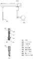
- FIG. 2 is an enlarged view of the specimen dispensing mechanism.
- the sample dispensing mechanism will be described, but the present invention can also be applied to a reagent dispensing mechanism.
- the specimen is also referred to as a sample.
- a high pressure pump is connected to the flow path of the nozzle 204.
- segmented air 203 is sucked in order to prevent contact between the sample 201 and the nozzle and the system water 202 in the flow path.
- the nozzle 204 rotates and descends on the sample container 205 (sample container 110) to detect the liquid level.
- a dummy sample 207 for eliminating the influence of thinning of the sample is sucked.
- the sample probe rises, rotates on the reaction vessel, descends to the bottom of the reaction vessel, and discharges the sample. At this time, only the measurement sample is discharged without discharging the dummy sample 207 on the reaction vessel.
- the probe is washed by an outer washing operation in which it moves to the washing tank and sprays washing water on the outer wall of the probe, and the inside of the probe is washed by an inner washing operation in which the system water supplied from the water supply tank and pressurized by the high-pressure pump 208 is poured out .
- the system water is poured out by a high-pressure pump as shown at 209.
- the internal washing operation is not performed when the same sample is repeatedly dispensed, but is performed when the next sample is dispensed.
- the electrical physical quantity is a voltage value, a capacitance value, or the like.
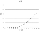
- FIG. 3 shows the system water when the dispensing operation is repeated without the internal washing operation under the condition where the segmental air is not normally secured or the abnormal condition such as the situation where the amount of the segmental air is reduced and the contamination is likely to occur.
- FIG. 3 shows data obtained by converting the amount of change in capacitance into a voltage value. Further, the amount of change in capacitance was measured at the upper limit point after the nozzle sucked the liquid and the probe before dispensing was movable. Further, the electrostatic capacity is a value between the nozzle and the GND level, and the converted voltage value is also a value between the nozzle and the GND level.
- the output value of the capacitance detection mechanism 117 a position where the nozzle 116 (204) is not in contact with the sample, for example, the capacitance value C1 at the upper limit point is used.
- the nozzle 116 (204) is made of a conductive material. If the movement of the system water is repeated under an abnormal condition where segmental air is not normally secured during dispensing, contamination between the specimen and the system water is caused. As a result, since the specimen contains ions such as an electrolyte, the system water having low conductivity because of purified water has conductivity. Therefore, by providing a detection mechanism for detecting the conductivity of the system water, it is possible to detect the contamination of the specimen into the system water.
- the capacitance value measured by the capacitance detection mechanism 117 is not contaminated due to the conductivity of the system water. Shift.
- the area that can be regarded as the nozzle side electrode increases when the system water has electrical conductivity and makes electrical contact with the electrode on the nozzle side. Since a circuit is built in which the voltage increases as the capacitance value on the nozzle side increases, the capacitance value increases as the area that can be regarded as an electrode increases due to the conductivity of the system water, and the voltage gradually increases as shown in FIG. Become bigger. Further, as the conductivity of the system water increases, the capacitance value increases, so that the voltage value gradually increases as shown in FIG. Accordingly, by providing a detection mechanism that detects the voltage value or capacitance value, which is an electrical physical quantity, in the nozzle 116 (204), it is possible to detect mixing of the specimen into the system water. Note that when a circuit is constructed in which the voltage decreases as the capacitance value on the nozzle side increases, the change amount of the voltage value changes to the negative side.
- the detection mechanism detects from the relationship between the amount of thinning due to the liquid system water and the amount of change in the electrical physical quantity, the storage unit storing the allowable range of the amount of thinning, and this relationship stored in the storage unit.
- the change amount of the electrical physical quantity can be converted into the thinning amount of the liquid. This conversion can be performed by the control unit 115, and the control unit 115 can determine whether the converted thinning amount is within the stored allowable range. In addition, this determination can be performed similarly with respect to the conductivity and electrical physical quantity of the system water.
- the control unit 115 (1) stops dispensing of the liquid when the nozzle exceeds the allowable value before dispensing the liquid into the reaction container. (2) The inner washing of the dispensing nozzle is performed. The dispensing nozzle holds new system water and dispenses the same liquid again.
- attaching a data flag means attaching a mark to a measurement result in order to distinguish between a measurement result measured within an allowable range and a measurement result measured beyond the allowable range.
- another threshold value may be provided in the range of the allowable value, and the control unit may perform any of the above processes before the threshold value is exceeded and the allowable value is exceeded. In this case, this threshold value can be considered as an allowable value.
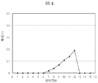
- FIG. 4 is an example of a voltage change when the same liquid is repeatedly dispensed while retaining the system water, and internal washing is performed during the dispensing. And as an example of eliminating the thinning by the internal washing and re-dispensing operation, when the thinning equivalent to the voltage 0.2V is the allowable limit, as shown in FIG. 4, it is predicted that the allowable value will be exceeded at the thirteenth time Therefore, the thinning is eliminated by performing the internal washing operation after the twelfth dispensing, and the analysis can be continued within the allowable range. The same can be done for the conductivity and electrical physical quantity of the system water.
- the capacitance value which is an electrical physical quantity
- the conductivity of the system water and the detection of the electrical physical quantity are detected at each dispensing.
- the detection may be performed at the timing when the nozzles are at the same height, and the present invention is not limited to the detection at the upper limit point. In short, the timing does not matter as long as it can be detected under the same height condition. If different samples are used, the detection timing of each sample may be changed. Especially when the same liquid is repeatedly dispensed while the system nozzle holds the system water, it is detected under the same height condition.
- the detection is performed at the timing when the dispensing nozzle is at the same height.
- the upper limit of the vertical drive of the nozzle is farthest from the sample container that causes a change in capacitance etc. at the position farthest from the apparatus, it is electrically relatively stable. Detection is most desirable.
- this electrostatic capacity detection mechanism calculates the electrical conductivity by calculating the electrical conductivity of the system water from the electrical physical quantity. It can also be detected. This is because the degree of conductivity of the system water also changes depending on the degree of change in capacitance.
- a detection mechanism a pair of electrodes may be provided in a pipe filled with system water separately, and the conductivity of the system water may be detected from the voltage value or resistance value between the electrodes.
- some nozzles have a capacitance detection mechanism that detects the liquid level of the specimen by detecting the amount of change in capacitance.
- this capacitance detection The mechanism may be integrated with the detection mechanism, and the detection mechanism may include a capacitance detection mechanism. That is, the same detection mechanism may be used to perform so-called liquid level detection and detection of conductivity and electrical physical quantity according to the present invention. In this case, since it can be a common circuit, there are merits such as omission of parts and the like and miniaturization by sharing.
- an example of an apparatus for determining whether or not the cleaning by the internal cleaning operation is sufficient will be described.
- the detection of the mixing of the sample into the system water when the same sample is repeatedly dispensed has been described.
- the washing degree of the inner washing and the system water used for the inner washing are changed. It is possible to detect an abnormality such as a failure or deterioration of the pump supplying the nozzle, a system water flow path, or the like.
- control unit 115 compares the electrical physical quantity detected by the detection mechanism with the system water in the state where the nozzle is filled with the system water and the reference value after the nozzle is washed, and the degree of washing of the inner wash from the comparison result. Can be determined. This is because if the contamination is not sufficiently eliminated, the sample is mixed in the system water, the conductivity becomes higher than the conductivity of the purified water, and the same phenomenon as in Example 1 occurs.
- FIG. 5 is an example showing the difference in voltage change due to the difference in conductivity of the suction liquid, and shows the relationship between the number of suctions and the voltage change due to the difference in conductivity.
- a blood sample has a low conductivity, and a detergent has a higher conductivity than a sample. For this reason, by allowing the detergent to be dispensed before the internal washing, the system water is easily conductive when compared with the same number of dispensing.
- the dispensing quantity is small by detecting the electrical physical quantity after dispensing highly conductive detergent, such as the timing of nozzle cleaning and the timing of adding a high-agent to the reaction tank
- the abnormality can be detected more accurately. Therefore, it is effective to detect the electrical physical quantity in the state that the nozzle is filled with system water and determine the degree of cleaning before dispensing the sample after the nozzle dispenses detergent. Is the method.
- the conductivity of the detergent is extremely high, the abnormality can be detected not only when the number of aspirations is plural, but also when the specimen is aspirated once.
- the backup process is effective such as performing the cleaning again while monitoring the electrical physical quantity, or stopping the analysis operation or continuing the analysis and assigning a data flag. . That is, any of the methods (1) to (3) in the first embodiment can be adopted.
- the present invention can also be applied to a reagent dispensing mechanism instead of a sample dispensing mechanism. Since other matters are the same as those in the first embodiment, description thereof is omitted.
Landscapes
- Physics & Mathematics (AREA)
- Health & Medical Sciences (AREA)
- Life Sciences & Earth Sciences (AREA)
- Chemical & Material Sciences (AREA)
- Analytical Chemistry (AREA)
- Biochemistry (AREA)
- General Health & Medical Sciences (AREA)
- General Physics & Mathematics (AREA)
- Immunology (AREA)
- Pathology (AREA)
- Engineering & Computer Science (AREA)
- Quality & Reliability (AREA)
- Automatic Analysis And Handling Materials Therefor (AREA)
Abstract
Description
102.ローター
103.試薬ディスク
104.反応槽
105.分注機構
106.攪拌機構
107.分光器
108.反応容器洗浄機構
109.ノズル洗浄機構
110.検体容器
111.検体ラック
112.反応容器
113.試薬容器
115.制御部
116.ノズル
117.静電容量検出機構
201.試料
202.システム水
203.分節空気
204.ノズル
205.検体容器
206.測定用試料
207.ダミー試料
208.高圧ポンプ
209.内洗中の状態
Claims (13)
- 検体と試薬とを反応容器に分注し反応容器内で反応した反応液の吸光度変化を利用して検体の分析を行う自動分析装置において、
検体又は試薬のいずれかの液体を反応容器に分注する分注ノズルと、
前記分注ノズル内の充填されたシステム水を移動させ、分節空気を介して前記分注ノズルに該液体の吸引及び吐出を行わせる分注機構と、
該システム水の導電率を検出する検出機構と、
を備えることを特徴とする自動分析装置。 - 請求項1記載の自動分析装置において、
前記分注ノズルが前記反応容器に液体を分注する前に、前記分注ノズル内に充填されたシステム水の導電率が許容値を超えた場合、
(1)液体の分注を停止させる
(2)前記分注ノズルの内洗を行い、前記分注ノズルは新たなシステム水を保持し、再度同一液体の分注を行う、
(3)液体の分注を継続し、継続して分注した液体を用いた分析結果にデータフラグを付する、
のいずれかを行うことを特徴とする自動分析装置。 - 請求項2記載の自動分析装置において、
さらに、前記検出機構は、該液体の液面高さを検出するための静電容量検出機構を含むことを特徴とする自動分析装置。 - 検体と試薬とを反応容器に分注し反応容器内で反応した反応液の吸光度変化を利用して検体の分析を行う自動分析装置において、
検体又は試薬のいずれかの液体を反応容器に分注する分注ノズルと、
前記分注ノズル内の充填されたシステム水を移動させ、分節空気を介して前記分注ノズルに該液体の吸引及び吐出を行わせる分注機構と、
前記分注ノズルに電荷を保持させ、システム水への該液体の混入に伴い変化する電気的物理量を検出する検出機構と、
を備えることを特徴とする自動分析装置。 - 請求項4記載の自動分析装置において、
前記分注ノズルが前記反応容器に液体を分注する前に、前記分注ノズル内に充填されたシステム水の前記電気的物理量が許容値を超えた場合、
(1)液体の分注を停止させる
(2)前記分注ノズルの内洗を行い、前記分注ノズルは新たなシステム水を保持し、再度同一液体の分注を行う、
(3)液体の分注を継続し、継続して分注した液体を用いた分析結果にデータフラグを付する、
のいずれかを行うことを特徴とする自動分析装置。 - 請求項5記載の自動分析装置において、
前記分注ノズルはシステム水を保持したまま同一液体を繰り返し分注し、
前記分注機構は、同一液体を繰り返し分注する際に、前記分注ノズルの上下駆動及び回転駆動を繰り返し、
前記検出機構は、分注の都度、前記分注ノズルが同じ高さとなるタイミングで前記電気的物理量を検出し、システム水への該液体の混入を検出することを特徴とする自動分析装置。 - 請求項6記載の自動分析装置において、
前記同じ高さは、前記分注ノズルの上下駆動の上限点の位置であることを特徴とする自動分析装置。 - 請求項4記載の自動分析装置において、
さらに、予め液体のシステム水による薄まり量と前記電気的物理量の変化量との関係、及び、薄まり量の許容範囲を記憶した記憶部と、
前記記憶部に記憶された前記関係から、前記検出機構が検出した前記電気的物理量の変化量を液体の薄まり量に変換する制御部と、を備え、
前記制御部は、変換された薄まり量が、前記許容範囲かどうかを判定することを特徴とする自動分析装置。 - 請求項4記載の自動分析装置において、
前記分注ノズルの内洗をした後に、前記分注ノズル内にシステム水を充填した状態で前記検出機構が検出した前記電気的物理量と基準値とを比較し、当該比較結果から当該内洗の洗浄度合いを判定する制御部と、
を備えることを特徴とする自動分析装置。 - 請求項9記載の自動分析装置において、
制御部は、前記洗浄度合いを判定することで、当該内洗に用いるシステム水を前記分注ノズルに供給するポンプの故障、又は劣化、並びに、システム水の流路に異常が発生していることのいずれかを検出することを特徴とする自動分析装置。 - 請求項10記載の自動分析装置において、
前記内洗は、前記分注ノズルが洗剤を分注した後で他の液体を分注する前の、内洗であることを特徴とする自動分析装置。 - 請求項4又は9記載の自動分析装置において、
前記検出機構は、前記電気的物理量のうち静電容量の変化量を検出することで、吸引する液体の液面高さを検出することを特徴とする自動分析装置。 - 請求項4~12のいずれか記載の自動分析装置において、
前記電気的物理量は、前記分注プローブの電圧値、又は、静電容量値であることを特徴とする自動分析装置。
Priority Applications (4)
| Application Number | Priority Date | Filing Date | Title |
|---|---|---|---|
| CN201580005350.XA CN106415277B (zh) | 2014-01-30 | 2015-01-16 | 自动分析装置 |
| US15/109,824 US9964558B2 (en) | 2014-01-30 | 2015-01-16 | Automatic analyzer |
| JP2015559865A JP6607787B2 (ja) | 2014-01-30 | 2015-01-16 | 自動分析装置 |
| EP15743833.4A EP3101432B1 (en) | 2014-01-30 | 2015-01-16 | Automatic analysis device |
Applications Claiming Priority (2)
| Application Number | Priority Date | Filing Date | Title |
|---|---|---|---|
| JP2014015057 | 2014-01-30 | ||
| JP2014-015057 | 2014-01-30 |
Publications (1)
| Publication Number | Publication Date |
|---|---|
| WO2015115200A1 true WO2015115200A1 (ja) | 2015-08-06 |
Family
ID=53756777
Family Applications (1)
| Application Number | Title | Priority Date | Filing Date |
|---|---|---|---|
| PCT/JP2015/050999 Ceased WO2015115200A1 (ja) | 2014-01-30 | 2015-01-16 | 自動分析装置 |
Country Status (5)
| Country | Link |
|---|---|
| US (1) | US9964558B2 (ja) |
| EP (1) | EP3101432B1 (ja) |
| JP (1) | JP6607787B2 (ja) |
| CN (1) | CN106415277B (ja) |
| WO (1) | WO2015115200A1 (ja) |
Cited By (4)
| Publication number | Priority date | Publication date | Assignee | Title |
|---|---|---|---|---|
| EP3147027A1 (en) * | 2015-09-28 | 2017-03-29 | Shimadzu Corporation | Liquid dispensing device and liquid dispensing method |
| JP2020052002A (ja) * | 2018-09-28 | 2020-04-02 | 日本電子株式会社 | 自動分析装置、および自動分析方法 |
| WO2025052751A1 (ja) | 2023-09-06 | 2025-03-13 | 株式会社日立ハイテク | 自動分析装置、分注ノズル洗浄状態判定方法、およびプログラム |
| WO2025249038A1 (ja) * | 2024-05-30 | 2025-12-04 | 株式会社日立ハイテク | 自動分析装置、異常判定方法およびプログラム |
Families Citing this family (5)
| Publication number | Priority date | Publication date | Assignee | Title |
|---|---|---|---|---|
| US20230341425A1 (en) * | 2019-10-24 | 2023-10-26 | Hitachi High-Tech Corporation | Automatic analyzer and dispensing method of reagent |
| JP7417463B2 (ja) * | 2020-04-24 | 2024-01-18 | 株式会社日立ハイテク | 分注装置、自動分析装置、分注方法 |
| CN114308849B (zh) * | 2020-09-29 | 2023-04-18 | 深圳市帝迈生物技术有限公司 | 避免液面误检测的方法以及样本分析仪 |
| EP4481391A4 (en) * | 2022-02-14 | 2026-02-25 | Hitachi High Tech Corp | COMPONENT FAULT DETECTION SYSTEM, AUTOMATED ANALYSIS DEVICE AND COMPONENT FAULT DETECTION METHOD |
| CN116338220B (zh) * | 2023-03-24 | 2026-06-30 | 深圳市科曼医疗设备有限公司 | 一种体外诊断仪器采样针混匀样本液的方法及应用 |
Citations (4)
| Publication number | Priority date | Publication date | Assignee | Title |
|---|---|---|---|---|
| JPH05256858A (ja) | 1992-03-16 | 1993-10-08 | Hitachi Ltd | 自動分析装置のサンプル分注方法 |
| JPH10115623A (ja) * | 1996-10-14 | 1998-05-06 | Aloka Co Ltd | 分注装置及びその制御方法 |
| JP2008309777A (ja) * | 2007-05-15 | 2008-12-25 | Hitachi High-Technologies Corp | 液体分注装置 |
| JP2010190681A (ja) * | 2009-02-17 | 2010-09-02 | Beckman Coulter Inc | 自動分析装置とその純水管理方法 |
Family Cites Families (5)
| Publication number | Priority date | Publication date | Assignee | Title |
|---|---|---|---|---|
| JPH0833320B2 (ja) * | 1986-03-20 | 1996-03-29 | 株式会社東芝 | 自動化学分析装置 |
| JP3674503B2 (ja) * | 2000-11-28 | 2005-07-20 | 株式会社日立製作所 | 自動分析装置及び自動分析装置の液面検出方法 |
| WO2007086477A1 (ja) * | 2006-01-27 | 2007-08-02 | Kabushiki Kaisha Toshiba | 自動分析装置及びプローブ昇降方法 |
| JP5255498B2 (ja) * | 2009-03-30 | 2013-08-07 | シスメックス株式会社 | 試薬調製装置および検体処理システム |
| JP5550364B2 (ja) | 2010-01-26 | 2014-07-16 | シスメックス株式会社 | 試薬調製装置 |
-
2015
- 2015-01-16 EP EP15743833.4A patent/EP3101432B1/en active Active
- 2015-01-16 CN CN201580005350.XA patent/CN106415277B/zh active Active
- 2015-01-16 JP JP2015559865A patent/JP6607787B2/ja active Active
- 2015-01-16 WO PCT/JP2015/050999 patent/WO2015115200A1/ja not_active Ceased
- 2015-01-16 US US15/109,824 patent/US9964558B2/en active Active
Patent Citations (4)
| Publication number | Priority date | Publication date | Assignee | Title |
|---|---|---|---|---|
| JPH05256858A (ja) | 1992-03-16 | 1993-10-08 | Hitachi Ltd | 自動分析装置のサンプル分注方法 |
| JPH10115623A (ja) * | 1996-10-14 | 1998-05-06 | Aloka Co Ltd | 分注装置及びその制御方法 |
| JP2008309777A (ja) * | 2007-05-15 | 2008-12-25 | Hitachi High-Technologies Corp | 液体分注装置 |
| JP2010190681A (ja) * | 2009-02-17 | 2010-09-02 | Beckman Coulter Inc | 自動分析装置とその純水管理方法 |
Cited By (5)
| Publication number | Priority date | Publication date | Assignee | Title |
|---|---|---|---|---|
| EP3147027A1 (en) * | 2015-09-28 | 2017-03-29 | Shimadzu Corporation | Liquid dispensing device and liquid dispensing method |
| JP2020052002A (ja) * | 2018-09-28 | 2020-04-02 | 日本電子株式会社 | 自動分析装置、および自動分析方法 |
| JP7181037B2 (ja) | 2018-09-28 | 2022-11-30 | 日本電子株式会社 | 自動分析装置、および自動分析方法 |
| WO2025052751A1 (ja) | 2023-09-06 | 2025-03-13 | 株式会社日立ハイテク | 自動分析装置、分注ノズル洗浄状態判定方法、およびプログラム |
| WO2025249038A1 (ja) * | 2024-05-30 | 2025-12-04 | 株式会社日立ハイテク | 自動分析装置、異常判定方法およびプログラム |
Also Published As
| Publication number | Publication date |
|---|---|
| EP3101432A1 (en) | 2016-12-07 |
| CN106415277B (zh) | 2018-05-01 |
| EP3101432B1 (en) | 2019-08-07 |
| CN106415277A (zh) | 2017-02-15 |
| US20160327586A1 (en) | 2016-11-10 |
| JPWO2015115200A1 (ja) | 2017-03-23 |
| JP6607787B2 (ja) | 2019-11-20 |
| EP3101432A4 (en) | 2017-11-08 |
| US9964558B2 (en) | 2018-05-08 |
Similar Documents
| Publication | Publication Date | Title |
|---|---|---|
| JP6607787B2 (ja) | 自動分析装置 | |
| JP4966913B2 (ja) | 液体分注装置 | |
| CN101952730B (zh) | 清洗装置和自动分析装置 | |
| EP3415921B1 (en) | Automated analyzer | |
| CN114787634B (zh) | 自动分析装置 | |
| WO2017145672A1 (ja) | 自動分析装置および洗浄方法 | |
| JPH01141357A (ja) | 自動分析装置のサンプル分注方法 | |
| US20230341425A1 (en) | Automatic analyzer and dispensing method of reagent | |
| JP2010071766A (ja) | 分注装置、自動分析装置および分注不良確認方法 | |
| JP6368536B2 (ja) | 自動分析装置および分析方法 | |
| JP5222784B2 (ja) | 液体のサンプリング方法、及び自動分析装置 | |
| JP2007315969A (ja) | 自動分析装置および分注機構の分注異常判定方法 | |
| EP3578994A1 (en) | Automatic analyzer | |
| JP7417463B2 (ja) | 分注装置、自動分析装置、分注方法 | |
| JP2015031586A (ja) | 分析装置及び液体吸引装置 | |
| EP3859349B1 (en) | Test method and dispensing device | |
| US10884009B2 (en) | Automated analyzer | |
| JP3120180U (ja) | 自動分析装置 | |
| CN118401842A (zh) | 自动分析装置、分注方法 | |
| CN116940847A (zh) | 自动分析装置 | |
| WO2010150502A1 (ja) | 自動分析装置 | |
| JP7002669B2 (ja) | 自動分析装置 | |
| WO2026070070A1 (ja) | 自動分析装置 | |
| WO2025052751A1 (ja) | 自動分析装置、分注ノズル洗浄状態判定方法、およびプログラム |
Legal Events
| Date | Code | Title | Description |
|---|---|---|---|
| 121 | Ep: the epo has been informed by wipo that ep was designated in this application |
Ref document number: 15743833 Country of ref document: EP Kind code of ref document: A1 |
|
| ENP | Entry into the national phase |
Ref document number: 2015559865 Country of ref document: JP Kind code of ref document: A |
|
| WWE | Wipo information: entry into national phase |
Ref document number: 15109824 Country of ref document: US |
|
| REEP | Request for entry into the european phase |
Ref document number: 2015743833 Country of ref document: EP |
|
| WWE | Wipo information: entry into national phase |
Ref document number: 2015743833 Country of ref document: EP |
|
| NENP | Non-entry into the national phase |
Ref country code: DE |