WO2015108161A1 - 電子機器、撮像装置及び通信装置 - Google Patents
電子機器、撮像装置及び通信装置 Download PDFInfo
- Publication number
- WO2015108161A1 WO2015108161A1 PCT/JP2015/051133 JP2015051133W WO2015108161A1 WO 2015108161 A1 WO2015108161 A1 WO 2015108161A1 JP 2015051133 W JP2015051133 W JP 2015051133W WO 2015108161 A1 WO2015108161 A1 WO 2015108161A1
- Authority
- WO
- WIPO (PCT)
- Prior art keywords
- unit
- imaging
- user
- control unit
- image
- Prior art date
- Legal status (The legal status is an assumption and is not a legal conclusion. Google has not performed a legal analysis and makes no representation as to the accuracy of the status listed.)
- Ceased
Links
Images



















Classifications
-
- G—PHYSICS
- G06—COMPUTING OR CALCULATING; COUNTING
- G06F—ELECTRIC DIGITAL DATA PROCESSING
- G06F3/00—Input arrangements for transferring data to be processed into a form capable of being handled by the computer; Output arrangements for transferring data from processing unit to output unit, e.g. interface arrangements
- G06F3/01—Input arrangements or combined input and output arrangements for interaction between user and computer
- G06F3/011—Arrangements for interaction with the human body, e.g. for user immersion in virtual reality
- G06F3/013—Eye tracking input arrangements
-
- G—PHYSICS
- G02—OPTICS
- G02B—OPTICAL ELEMENTS, SYSTEMS OR APPARATUS
- G02B27/00—Optical systems or apparatus not provided for by any of the groups G02B1/00 - G02B26/00, G02B30/00
- G02B27/01—Head-up displays
- G02B27/017—Head mounted
-
- G—PHYSICS
- G02—OPTICS
- G02B—OPTICAL ELEMENTS, SYSTEMS OR APPARATUS
- G02B27/00—Optical systems or apparatus not provided for by any of the groups G02B1/00 - G02B26/00, G02B30/00
- G02B27/01—Head-up displays
- G02B27/0101—Head-up displays characterised by optical features
- G02B2027/0138—Head-up displays characterised by optical features comprising image capture systems, e.g. camera
-
- G—PHYSICS
- G02—OPTICS
- G02B—OPTICAL ELEMENTS, SYSTEMS OR APPARATUS
- G02B27/00—Optical systems or apparatus not provided for by any of the groups G02B1/00 - G02B26/00, G02B30/00
- G02B27/01—Head-up displays
- G02B27/0101—Head-up displays characterised by optical features
- G02B2027/014—Head-up displays characterised by optical features comprising information/image processing systems
-
- G—PHYSICS
- G02—OPTICS
- G02B—OPTICAL ELEMENTS, SYSTEMS OR APPARATUS
- G02B27/00—Optical systems or apparatus not provided for by any of the groups G02B1/00 - G02B26/00, G02B30/00
- G02B27/01—Head-up displays
- G02B27/0101—Head-up displays characterised by optical features
- G02B2027/0141—Head-up displays characterised by optical features characterised by the informative content of the display
-
- G—PHYSICS
- G02—OPTICS
- G02B—OPTICAL ELEMENTS, SYSTEMS OR APPARATUS
- G02B27/00—Optical systems or apparatus not provided for by any of the groups G02B1/00 - G02B26/00, G02B30/00
- G02B27/01—Head-up displays
- G02B27/017—Head mounted
- G02B2027/0178—Eyeglass type
-
- G—PHYSICS
- G02—OPTICS
- G02B—OPTICAL ELEMENTS, SYSTEMS OR APPARATUS
- G02B23/00—Telescopes, e.g. binoculars; Periscopes; Instruments for viewing the inside of hollow bodies; Viewfinders; Optical aiming or sighting devices
- G02B23/14—Viewfinders
-
- G—PHYSICS
- G03—PHOTOGRAPHY; CINEMATOGRAPHY; ANALOGOUS TECHNIQUES USING WAVES OTHER THAN OPTICAL WAVES; ELECTROGRAPHY; HOLOGRAPHY
- G03B—APPARATUS OR ARRANGEMENTS FOR TAKING PHOTOGRAPHS OR FOR PROJECTING OR VIEWING THEM; APPARATUS OR ARRANGEMENTS EMPLOYING ANALOGOUS TECHNIQUES USING WAVES OTHER THAN OPTICAL WAVES; ACCESSORIES THEREFOR
- G03B13/00—Viewfinders; Focusing aids for cameras; Means for focusing for cameras; Autofocus systems for cameras
- G03B13/02—Viewfinders
Definitions
- the present invention relates to an electronic device, an imaging device, and a communication device.
- the present invention has been made in view of the above problems, and an object of the present invention is to provide an electronic device, an imaging device, and a communication device that can contribute to improvement of user-friendliness.
- the electronic device of the present invention includes a display unit that can display an image captured by an external device in the vicinity of the user's eyes, a gaze detection unit that detects the gaze of the user, and information according to a detection result of the gaze detection unit And a transmission unit for transmitting to the external device.
- the transmission unit may transmit information related to focus detection of the external device.
- the electronic device includes a display unit that can display an image captured by an external device in the vicinity of the user's eyes, a detection unit that detects the user's specific operation, and the detection unit is a specific operation of the user.
- a transmission unit that transmits information according to the timing at which the signal is detected to the external device.
- the transmission unit may transmit information for specifying a posture in which the external device captures an image.
- the detection unit may detect a specific action of the user's eyes.
- An electronic device includes a first input unit that inputs information about an imaging region of an external device, a second input unit that inputs information about a user's line of sight, information about the imaging region of the external device, and the user's A display unit that displays information on the line of sight in the vicinity of the user's eyes.
- a transmission unit may be provided that transmits information for controlling the external device to the external device based on information on the imaging area of the external device and information on the user's line of sight.
- the display unit may display an image obtained by combining information on an imaging area of the external device and information on the user's line of sight with an image captured by the external device.
- the electronic device may include an authentication unit that authenticates the user.
- the authentication unit may display information related to the authentication result of the external device.
- the imaging device of the present invention includes a communication unit that communicates with the electronic device of the present invention, an authentication unit that authenticates a user, and an imaging unit that captures an image.
- a control unit may be provided that permits communication by the communication unit when the authentication result of the authentication unit matches the authentication result of the authentication unit of the electronic device.
- the imaging device of the present invention includes a communication unit that communicates with the electronic device of the present invention, and an imaging unit that captures an image, and the imaging unit is based on information transmitted from the transmission unit of the electronic device. Execute the process.
- the communication device of the present invention includes a first authentication result input unit that inputs a user authentication result of the electronic device of the present invention, a second authentication result input unit that inputs a user authentication result of the imaging device, and the first authentication.
- a control unit that permits communication between the electronic device and the imaging device when the authentication result input by the result input unit matches the authentication result input by the second authentication result input unit; ing.
- the communication device of the present invention includes a first information input unit that inputs information about the user's line of sight from an electronic device, a second information input unit that inputs information about an imaging region of the imaging device, and an imaging region of the imaging device.
- a comparison unit that compares information with information about the user's line of sight.
- a communication unit capable of transmitting a through image captured by the imaging unit to an external device, communication between the communication unit and the external device is established, and the imaging unit captures the through image.
- a control unit that waits for transmission of the through image captured by the imaging unit is provided.
- the imaging apparatus includes a first input unit that inputs an imaging direction of the imaging unit, a second input unit that inputs a direction in which an external device worn by a user is facing, and the first input unit that inputs the first input unit.
- a control unit that controls the imaging unit based on an imaging direction and a direction input by the second input unit.
- An electronic device is an electronic device worn by a user, and includes a first input unit that inputs an imaging direction of an imaging apparatus, a second input unit that inputs a direction in which the electronic device is facing, and the user Based on the imaging direction input by the first input unit and the direction input by the second input unit, the input received by the input receiving unit is input to the imaging device.
- a transmission unit that transmits the operation information to the imaging apparatus.
- the electronic device, the imaging device, and the communication device according to the present invention have an effect of being able to contribute to improvement of user convenience.
- FIG. 1 is a diagram illustrating a configuration of an imaging system according to a first embodiment. It is a perspective view of a mounting apparatus. 3A is a front view of the imaging apparatus, and FIG. 3B is a rear view of the imaging apparatus. It is a flowchart which shows the preparation process performed in a mounting apparatus. It is a flowchart which shows the preparatory process performed in an imaging device. It is a flowchart which shows the cooperation imaging
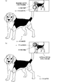
- FIG. 13A is a diagram illustrating a case where the user's gaze is outside the range of the dog's face
- FIG. 13B is a diagram where the user's gaze is the range of the dog's face.
- FIG. 14A is a diagram illustrating a state in which an enlarged image of the dog's face is displayed
- FIG. 14B is a diagram illustrating a state in which a live view image is displayed after the line of sight is detected.
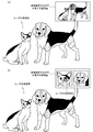
- FIG. 15A shows a state in which a plurality of main subjects are present in the user's actual field of view and a live view image is displayed in the displayable range of the display unit of the mounting apparatus in the modified example (part 2).
- FIG. 15B is a diagram illustrating a state in which the face portions of cats and dogs are displayed in the displayable range of the display unit of the mounting device. It is a figure which shows the example using a server in 1st Embodiment.
- FIG. 21A is a diagram illustrating a case where the imaging range of the imaging apparatus is not included in the displayable range
- FIG. 21B is a display example of a live view image in the case of FIG.
- FIG. 22A is a diagram illustrating a case where the shooting range is equal to or smaller than a predetermined size
- FIG. 22A is a diagram illustrating a case where the shooting range is equal to or smaller than a predetermined size
- FIG. 22B is a diagram illustrating a display example of a live view image in the case of FIG. 22A. It is a figure which shows the example of a display when a user wears the contact lens type display apparatus. It is a flowchart which shows the cooperation imaging
- FIG. 25A is a diagram illustrating the state of the user in the third embodiment
- FIG. 25B is a diagram illustrating the movement of the imaging apparatus in the third embodiment.
- FIG. 26A and FIG. 26B are diagrams for explaining the processing of FIG. It is a figure which shows the modification of 3rd Embodiment. It is a flowchart which shows the cooperation imaging
- FIGS. 30A and 30B are diagrams (part 1) for explaining the processing of FIG.
- FIGS. 30A and 30B are diagrams (part 2) for explaining the processing of FIG.
- It is a block diagram which shows the structure of the imaging system which concerns on 5th Embodiment.
- FIG. 32A is a perspective view illustrating an example of a wearable device
- FIG. 32B is a perspective view illustrating an example of an imaging apparatus.
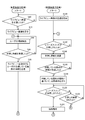
- FIG. 33A is a flowchart illustrating an example of processing executed by the imaging apparatus according to the fifth embodiment
- FIG. 33B is an example of processing executed by the wearable device according to the fifth embodiment. It is a flowchart which shows. It is a figure showing the condition which is using the imaging system concerning 5th Embodiment.
- 16 is a flowchart illustrating an example of processing executed by an imaging apparatus according to a sixth embodiment. It is a figure showing the condition which is using the imaging system which concerns on 7th Embodiment. It is a flowchart which shows an example of the process which the wearable apparatus which concerns on 7th Embodiment performs.
- FIG. 1 is a block diagram showing the configuration of the imaging system 100 according to the first embodiment.
- the imaging system 100 includes (uses) a mounting device 10 and an imaging device 20.
- the wearing device 10 is a terminal that a user wears on the body (face), and has an eyeglass shape as an example.
- the mounting apparatus 10 includes an imaging unit 101, a display unit 102, an operation unit 103, a microphone 104, a speaker 105, a direction sensor 106, a pupil imaging unit 107, and a line-of-sight detection unit 108.
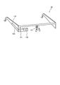
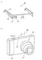
- the mounting device 10 is shown in a perspective view.
- the mounting apparatus 10 includes a glasses-type frame 120.
- the configuration of the mounting apparatus 10 illustrated in FIG. 1 and not illustrated in FIG. 2 is provided inside the frame 120 or a part of the frame 120.
- the imaging unit 101 includes a lens, an imaging device, an image processing unit, and the like, and captures still images and moving images. As shown in FIG. 2, the imaging unit 101 is provided near the end of the frame 120 (near the user's right eye). For this reason, in a state where the user wears the mounting device 10, it is possible to capture an image in a direction in which the user is facing (viewing).
- the display unit 102 includes a projector provided in or near the frame 120, and a prism for guiding a projection image from the projector to the eyes of the user.
- the display unit 102 displays various information under the control of the control unit 111.
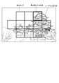
- the displayable range of the display unit 102 is, for example, a range shown in FIG. 8 (upper right range of the user's actual field of view).
- the operation unit 103 is a touch pad provided on the frame 120, detects the movement of the user's finger, receives an operation from the user, and transmits the received operation information to the control unit 111. Details of the imaging unit 101, the display unit 102, the operation unit 103, and the like are also disclosed in, for example, US Published Patent No. 2013/0044042.
- the microphone 104 is provided in the frame 120 and collects voices uttered by the user.
- the voice collected by the microphone 104 is voice-recognized by a voice recognition unit (not shown), and the voice recognition result is transmitted to the control unit 111.
- the control unit 111 executes processing based on the voice recognition result (for example, command execution processing). Note that the control unit 111 may perform voice recognition.
- the speaker 105 is an audio output device that is provided in the frame 120 and outputs audio under the control of the control unit 111, for example.
- a speaker having directivity and capable of providing audio information mainly toward the ear of the user wearing the wearing device 10 can be employed.
- the direction sensor 106 detects the direction in which the mounting device 10 is directed, for example, based on geomagnetism.
- the orientation sensor 106 detects a direction (imaging direction) in which the imaging unit 101 of the mounting apparatus 10 is facing, that is, a direction in which the user wearing the mounting apparatus 10 is facing (looking), Output to the control unit 111.
- the pupil imaging unit 107 is provided in the vicinity of the right eye of the user wearing the mounting device 10, and images the pupil of the user's right eye under the control of the control unit 111. An image captured by the pupil imaging unit 107 is transmitted to the control unit 111 and used for iris authentication and line-of-sight detection described later. Note that the pupil imaging unit 107 may image the pupil of the user's left eye.
- the line-of-sight detection unit 108 detects the direction of the line of sight of the user wearing the mounting apparatus 10 based on the image captured by the pupil imaging unit 107.
- the line-of-sight detection may be performed using, for example, a device having an infrared irradiation unit and an infrared light receiving unit.
- the user's line-of-sight direction is detected based on the light reception result of irradiating the eyeball with infrared rays from the infrared irradiation unit and receiving the infrared rays reflected by the eyeballs with the infrared light receiving unit.
- the person authentication unit 109 performs iris authentication based on the image captured by the pupil imaging unit 107. Specifically, the person authentication unit 109 associates and stores an iris image of the user and user information (user ID) and stores the iris authentication DB (stored in the storage unit 112) and the captured iris. Authentication is performed using images. Note that iris authentication is disclosed in, for example, Japanese Patent No. 5360931.
- the communication unit 110 wirelessly communicates with other devices (communication using a mobile phone line or a wireless LAN (Local Area Network)), proximity communication (for example, Bluetooth (registered trademark), RFID (Radio Frequency Identification), Transfer Jet, or the like. (Registered trademark)).
- the communication unit 110 performs close proximity communication with the imaging device 20.
- the communication part 110 may perform human body communication which communicates via a user (human body).
- an electrode for human body communication may be disposed at a portion of the frame 120 that contacts the user.
- Human body communication includes a current method in which a weak current is passed through the human body and the current is modulated to transmit information, and an electric field method in which an electric field induced on the surface of the human body is modulated to transmit information. Any method can be used.
- the control unit 111 controls the entire mounting device 10 in an integrated manner.
- the control unit 111 includes a CPU (Central Processing Unit), a RAM (Random Access Memory), a ROM (Read Only Memory), and the like. Details of the processing executed by the control unit 111 will be described later.
- the storage unit 112 is, for example, a nonvolatile semiconductor memory such as a flash memory, and stores image data captured by the imaging unit 101, display data displayed on the display unit 102, iris authentication DB used by the person authentication unit 109, and the like.
- a nonvolatile semiconductor memory such as a flash memory
- the imaging device 20 is, for example, a camera, a mobile phone having an imaging function, a smartphone, a tablet terminal, or the like. In the present embodiment, the imaging device 20 will be described as a camera. 3A shows a front view of the imaging device 20, and FIG. 3B shows a rear view of the imaging device 20. As shown in FIG.
- the imaging device 20 may be any of a single-lens reflex camera, a mirrorless camera, and a compact camera, but in this embodiment, as shown in FIGS. 3A and 3B, it is a compact camera. Shall.
- the imaging device 20 includes an imaging unit 201, a display unit 202, an operation unit 203, a microphone 204, a speaker 205, a storage unit 206, a communication unit 207, An azimuth sensor 208, a fingerprint sensor 209, a person authentication unit 210, a lens driving unit 212, a focus detection unit 213, and a control unit 211 are provided.
- the imaging unit 201 includes a lens, an imaging device, an image processing unit, and the like, and captures still images and moving images.
- the display unit 202 is, for example, an LCD (Liquid Crystal Display), and is provided on the surface of the imaging unit 201 opposite to the lens.
- the display unit 202 displays various setting information for the imaging device 20, an operation menu for operating the imaging device 20, icons, and the like.
- the display unit 202 displays a live view image (through image) captured by the imaging unit 201 and a still image or a moving image recorded in the storage unit 206 described later.
- the operation unit 203 is an operation member that receives an operation on the imaging apparatus 20 from a user, and includes a release switch 203A, a moving image imaging switch 203B, a menu switch 203C, a cross switch (multi-selector) 203D, a deletion switch 203E, a zoom lever 203F, and the like. (Refer to FIG. 3A and FIG. 3B).
- the release switch 203A is provided on the upper surface, and is operated (pressed) by the user when instructing to capture a still image, for example.
- the moving image capturing switch 203B is operated (pressed) by the user when instructing to capture moving images.
- the menu switch 203 ⁇ / b> C is operated by the user when displaying an operation menu or the like for setting imaging conditions on the display unit 202.
- the cross switch 203D has an OK switch at the center and up / down / left / right switches at the periphery, and the user selects a menu from the operation menu displayed on the display unit 202 by operating the cross switch 203D. Then, the imaging condition is set.
- the deletion switch 203E is a switch for deleting an image selected by operating the cross switch 203D when the image capturing apparatus 20 is in a reproduction mode for reproducing an image captured.
- the zoom lever 203F is a lever for changing the zoom position. When the user moves the zoom lever 203F, the lens in the imaging unit 201 is driven to change the zoom position.
- the operation unit 203 may include a touch panel provided on the display unit 202 or incorporated in the display unit 202.
- the touch panel detects a user's touch operation on the surface of the display unit 202 and receives various information inputs. That is, the user can operate the imaging device 20 by performing an operation of touching an operation menu or icon displayed on the display unit 202.
- the microphone 204 is an audio input device that is provided on the opposite surface of the display unit 202 and inputs audio when a still image or a moving image is captured.
- the speaker 205 is an audio output device that outputs audio based on audio data associated with still image data or moving image data.
- the speaker 205 is provided on the same surface as the display unit 202, for example.
- the storage unit 206 includes, for example, a connector connected to an SD card that is a storage medium that can be attached to and detached from the imaging device 20, and stores still image data and moving image data in the SD card.
- the storage unit 206 has an internal memory, and stores a fingerprint authentication DB (to be described later) in the internal memory.
- the communication unit 207 performs wireless communication (communication using a mobile phone line or a wireless LAN) and proximity communication with other devices. In the present embodiment, the communication unit 207 performs close proximity communication with the mounting apparatus 10. Note that the communication unit 207 may perform human body communication with other devices.
- the direction sensor 208 detects the direction in which the imaging unit 201 is directed based on, for example, geomagnetism, and outputs the detection result to the control unit 211.
- the fingerprint sensor 209 is provided on the surface of the release switch 203A or the moving image pickup switch 203B that the user touches when taking an image.
- the fingerprint sensor 209 detects the user's fingerprint and transmits the detection result to the control unit 211.
- the person authentication unit 210 performs user authentication using a fingerprint authentication DB (stored in the storage unit 206) that stores fingerprint information and user information (user ID) in association with each other and a detection result of the fingerprint sensor 209. I do.
- the authentication result by the person authentication unit 210 is transmitted to the control unit 211.
- the lens driving unit 212 includes, for example, a motor and an actuator, and drives a lens (focus lens) included in the imaging unit 201 in order to perform focusing.
- the lens driving unit 212 is driven and controlled by the control unit 211.
- the focus detection unit 213 performs focus determination based on the contrast value of the image signal output from the image sensor included in the imaging unit 201.
- the determination result of the focus detection unit 213 is transmitted to the control unit 211.
- the control unit 211 determines at least one of 11 rectangular areas shown in FIG. 10 as a focus detection position, and executes autofocus based on the contrast value of the image signal corresponding to the determined rectangular area.
- the focus detection unit 213 is not limited to the contrast detection method, and other methods such as a phase difference detection method may be used.
- the control unit 211 controls the entire imaging apparatus 20 in an integrated manner.
- the control unit 211 includes a CPU, RAM, ROM, and the like.
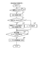
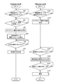
- FIG. 4 is a flowchart showing a preparation process executed in the mounting apparatus 10
- FIG. 5 is a flowchart showing a preparation process executed in the imaging apparatus 20.
- the preparatory processes in FIGS. 4 and 5 are processes for starting communication for executing the cooperative shooting mode when the imaging apparatus 20 is held by the user wearing the mounting apparatus 10.
- Step S 10 (Preparation processing by the mounting device 10) First, the preparation process by the mounting apparatus 10 is demonstrated along the flowchart of FIG. In the process of FIG. 4, the control unit 111 of the mounting apparatus 10 determines whether or not the mounting apparatus 10 is mounted by the user in step S ⁇ b> 10. Note that the control unit 111 may determine whether or not the mounting device 10 is mounted by the user from, for example, a detection result of a contact sensor provided inside the frame 120. When the user wears the wearing device 10, the control unit 111 proceeds to step S12.
- step S12 the control unit 111 instructs the pupil imaging unit 107 to capture an image of the user's pupil, and acquires an iris image from the captured image.
- step S14 the control unit 111 instructs the person authentication unit 109 to perform authentication using an iris image, and whether or not the iris image is included in the iris authentication DB as a result of the authentication. Judging.
- the iris authentication DB is a database that stores the iris image and user information (user ID) associated with each other and stored in the storage unit 112 as described above. If the determination in step S14 is negative, the process proceeds to step S16. If the determination is positive, the process proceeds to step S18.
- step S16 that is, when the iris image is not included in the iris authentication DB, the control unit 111 issues a new user ID and registers the iris image in the iris authentication DB. Thereafter, the control unit 111 proceeds to step S20.
- the new user ID is a combination of randomly selected alphanumeric characters.
- step S18 the control unit 111 acquires the user ID of the user wearing the mounting device 10 from the iris authentication DB. Thereafter, the control unit 111 proceeds to step S20.
- step S20 the control unit 111 waits until the user ID is requested from the imaging device 20. Then, at a timing when the user ID is requested from the imaging device 20, the process proceeds to step S ⁇ b> 22, and the control unit 111 transmits the user ID to the imaging device 20 via the communication unit 110.
- Step S ⁇ b> 110 the control unit 211 waits until fingerprint reading becomes possible in step S ⁇ b> 110. In this case, the control unit 211 waits until the user's finger touches the fingerprint sensor 209, and proceeds to step S112 when the user's finger is touched.
- step S112 the control unit 211 performs fingerprint reading using the fingerprint sensor 209.
- step S114 the control unit 211 issues an instruction to the person authentication unit 210, and determines whether the fingerprint reading result (fingerprint information) is included in the fingerprint authentication DB.
- the fingerprint authentication DB used in step S114 is a database that stores fingerprint information and user information (user ID) associated with each other and stored in the storage unit 206 as described above. If the determination in step S114 is negative, the process proceeds to step S116. If the determination is positive, the process proceeds to step S118.
- step S116 that is, when the fingerprint information is not included in the fingerprint authentication DB
- the control unit 211 issues a temporary user ID and registers the fingerprint information in the fingerprint authentication DB.
- the temporary user ID is a combination of randomly selected alphanumeric characters and is different from the user ID issued in step S16 of FIG. 4 described above. Thereafter, the control unit 211 proceeds to step S120.
- step S118 the control unit 211 acquires the user ID of the user wearing the imaging device 20 from the fingerprint authentication DB. Thereafter, the control unit 211 proceeds to step S120.
- step S120 When the process proceeds to step S120 via step S116 or S118, the control unit 211 is acquired in step S16 or step S18 of FIG. 4 from the mounting device 10 (control unit 111) by proximity communication via the communication unit 207. Request transmission of a user ID.
- step S122 the control unit 211 stands by until a user ID is received from the mounting apparatus 10.
- the process proceeds to step S124 at the timing when step S22 of FIG. If transfering it to step S124, the control part 211 will judge whether the user ID received from the mounting apparatus 10 and the user ID received by step S116 or step S118 correspond. If the determination in step S124 is affirmative, that is, if the user who wears the mounting apparatus 10 and holds the imaging apparatus 20 is a registered user, the process proceeds to step S126.
- step S ⁇ b> 126 the control unit 211 starts communication for executing the cooperative shooting mode with the mounting apparatus 10.
- the control unit 211 may display on the display unit 202 that communication has been started.
- step S ⁇ b> 126 the control unit 211 may display on the display unit 102 that communication has been started via the control unit 111.
- step S124 determines whether or not what is received from the mounting apparatus 10 is the new user ID acquired in step S16 of FIG. If the determination here is negative, that is, if the user wearing the mounting device 10 and the imaging device 20 are different, communication for executing the cooperative shooting mode with the mounting device 10 cannot be performed.
- step S130 the control unit 211 displays a message to that effect on the display unit 202.
- step S ⁇ b> 130 the control unit 211 may display a message on the display unit 102 via the control unit 111.
- step S128 determines whether the received user ID is the new user ID acquired in step S16 in FIG. 4 or notative. If the determination in step S128 is affirmative, that is, if the received user ID is the new user ID acquired in step S16 in FIG. 4, the control unit 211 proceeds to step S132, and step The temporary user ID issued in S116 is rewritten with a new user ID, and communication for executing the cooperative shooting mode is started.
- step S132 the control unit 211 may display on the display unit 202 (and / or the display unit 102) that a new user ID has been set and communication has been started. After the process of step S130 or S132 is performed, the entire process of FIG.
- FIGS. 4 and 5 when the mounting device 10 and the imaging device 20 perform human body communication, the processes in FIGS. 4 and 5 are omitted, and human body communication between the mounting device 10 and the imaging device 20 is established, and iris authentication or fingerprint is performed. You may make it start the communication for performing cooperation imaging
- NFC Near Field Communication
- step S140 the control unit 211 of the imaging device 20 starts transmitting a live view image in step S140. Thereafter, in step S142, the process waits until the release switch 203A is half-pressed by the user.
- control unit 111 waits until a live view image is received in step S40. Therefore, at the timing when the process of step S140 is performed on the imaging device 20 side, the control unit 111 proceeds to step S42.
- step S42 the control unit 111 displays a live view image on the display unit 102.
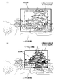
- FIG. 8 shows the user's real view and how the user sees the live view image displayed within the displayable range of the display unit 102. As shown in FIG. 8, a live view image is displayed on the upper right of the user's real field of view.
- step S44 the control unit 111 detects the user's line of sight via the line-of-sight detection unit 108.
- the line-of-sight detection unit 108 detects which position of the live view image in FIG. 8 the user is gazing at.
- the circle area is detected as the area the user is gazing at.
- step S46 the control unit 111 determines whether or not the half-press information has been received from the imaging device 20, but if the determination here is negative, the control unit 111 returns to step S44 and again the user's Perform eye gaze detection. On the other hand, if the determination in step S46 is affirmative, the process proceeds to step S48.
- step S142 the control unit 211 waits until the release switch is half-pressed by the user. The process proceeds to S144.
- step S144 the control unit 211 transmits half-press information indicating that the press is half-pressed to the control unit 111 of the mounting apparatus 10.
- step S48 the determination of step S46 is affirmed on the mounting device 10 side, and the control unit 111 proceeds to step S48. If transfering it to step S48, the control part 111 will transmit the information of the location which the user is gazing in among the live view images.
- the control unit 111 transmits position information (coordinate information in the live view image) of the circle area in FIG. 9 to the control unit 211 of the imaging device 20. Note that the control unit 111 returns to step S44 after step S48.
- step S146 it waits until it receives information on the location where the user is gazing, so at the timing when the processing of step S48 is performed in the mounting device 10.
- the control unit 211 proceeds to step S148.
- the control unit 211 controls the lens driving unit 212 and the focus detection unit 213 to perform a focusing operation based on the information on the location where the user is gazing. In this case, the control unit 211 determines which position of the captured image is to be focused based on a circle area indicating a gaze point.
- the imaging device included in the imaging unit 101 it is assumed that a plurality of (11 places) rectangular areas for performing focus detection are set as shown in FIG. In FIG. 10, the control unit 211 determines, for example, a rectangular area (area indicated by a thick line in FIG. 10) having the largest overlapping area with a spot (dashed circle area) as a focus position.
- the present invention is not limited to this.
- the control unit 211 drives the focus lens via the lens driving unit 212 and executes autofocus based on the contrast value of the image signal corresponding to the determined rectangular area.
- control unit 211 may transmit information on the determined rectangular area (coordinate information on the in-focus position in the live view image) to the control unit 111 of the mounting apparatus 10.
- the control unit 111 may display the received rectangular area information (in-focus location) on the live view image on the display unit 102.
- the display form such as the display color may be different between the display of the gaze location of the user in FIG. 9 and the display of the rectangular area (position to be focused) in FIG.
- step S150 the control unit 211 determines whether or not the release switch 203A is fully pressed by the user. If the determination here is affirmed, in step S154, the control unit 211 performs an imaging operation using the imaging unit 201. Thereby, an image can be picked up in a state in which the portion focused by the user is in focus. Thereafter, the process returns to step S142.
- step S150 determines whether or not the half-press of the release switch 203A is released. If the determination here is negative, that is, if the release switch 203A is half-pressed, the process returns to step S150. If the determination is affirmative, that is, if the half-press is released, The process returns to step S142.
- control unit 111 of the mounting apparatus 10 repeats the processes and determinations of steps S44 to S48 until the cooperative shooting mode is canceled, and the control unit 211 of the imaging apparatus 20 performs the processes and determinations of steps S142 to S154. repeat.
- the display unit 102 displays the live view image captured by the imaging device 20 in the vicinity of the user's eyes, and the line-of-sight detection unit 108 displays the live view.
- the line of sight of the user when the image is displayed is detected.
- the control unit 111 transmits information corresponding to the detection result of the line-of-sight detection unit 108 (information on a portion being watched by the user) to the imaging device 20 via the communication unit 110.
- the imaging device 20 it is possible to capture an image in a state in which the focus is set on the location where the user is gazing by performing the focusing operation based on the information on the location where the user is gazing. Become.
- the imaging device 20 can capture an image desired by the user by performing imaging based on the user's line-of-sight information transmitted from the mounting device 10.
- the mounting apparatus 10 includes a person authentication unit 109 that authenticates a user, and the control unit 211 of the imaging apparatus 20 includes an authentication result of the person authentication unit 210 of the imaging apparatus 20, and When the authentication results of the person authentication unit 109 match, communication for executing the cooperative shooting mode is started. Accordingly, when an appropriate user wears the mounting apparatus 10 and holds the imaging apparatus 20, the cooperative shooting mode can be executed.
- a message indicating that communication is not possible is displayed on the display unit 102 or 202 (S130), so that the user can cooperate by referring to the display unit 102 or 202. It becomes possible to recognize that the shooting mode cannot be executed.
- the live view image is displayed on the display unit 102 of the mounting apparatus 10, it is not necessary to provide the display unit 202 in the imaging apparatus 20. As a result, it is possible to reduce the manufacturing cost, the number of parts, the power consumption, and the like of the imaging device 20.
- control unit 211 of the imaging device 20 executes the processing / judgment of steps S124 to S132 in FIG. 5 (the verification process of the authentication result of the mounting device 10 and the authentication result of the imaging device 20).
- steps S124 to S132 in FIG. 5 the verification process of the authentication result of the mounting device 10 and the authentication result of the imaging device 20.
- the present invention is not limited to this, and may be executed by the control unit 111 of the mounting apparatus 10.
- the control unit 211 of the imaging device 20 detects the main subject in the live view image using an image recognition technique. For example, as shown in FIG. 12, it is assumed that a dog exists in the user's real field of view, and a dog image is displayed as a live view image in the displayable range of the display unit 102 of the mounting apparatus 10 (FIG. 6). S42). In this case, the control unit 211 detects the range of the dog's face from the live view image using image recognition technology.
- step S142 in FIG. 6 affirmative
- the control unit 111 of the mounting apparatus 10 captures information (coordinate information) of the portion of the live view image that the user is gazing at.
- the control unit 211 determines whether or not the portion that the user is gazing is within the range of the dog's face.
- the control unit 211 performs a focusing operation (S148 in FIG. 6) and an imaging operation (S154 in FIG. 6).
- the control unit 211 when the portion being watched by the user is within the face range of the dog (main subject), the control unit 211 has a predetermined size including the face of the dog. The range is cut out from the live view image and transmitted to the control unit 111 of the mounting apparatus 10. That is, the control unit 211 transmits an enlarged image of the dog's face to the control unit 111. As illustrated in FIG. 14A, the control unit 111 switches the live view image displayed on the display unit 102 to an enlarged image, and executes line-of-sight detection again. In this case, since the line of sight is detected on the enlarged image, it is possible to detect in detail whether the user's line of sight is directed to the eyes of the dog or the nose. Therefore, the control unit 211 of the imaging device 20 can perform appropriate focusing according to the user's preference.
- the control unit 211 transmits a live view image as shown in FIG. 14B to the control unit 111 of the mounting apparatus 10 again at the timing when the focus is adjusted.
- the control unit 111 switches the display on the display unit 102 from FIG. 14A to FIG. 14B. Accordingly, the user can perform imaging after confirming the imaging range (composition) and the in-focus position of the imaging device 20.
- the process of cutting out a predetermined size range including the face of the dog (main subject) from the live view image may be performed by the control unit 111 of the mounting apparatus 10 that has received the live view image.
- the control unit 211 of the imaging device 20 detects a plurality of main subjects in the live view image by using an image recognition technique. For example, as shown in FIG. 15A, dogs and cats exist in the user's actual field of view, and images of dogs and cats are displayed as live view images in the displayable range of the display unit 102 of the wearing apparatus 10. Suppose that it was (S42 of FIG. 6). In this case, the control unit 211 detects the range of the dog's face and the range of the cat's face from the live view image using image recognition technology.
- the control unit 211 of the imaging device 20 cuts out the predetermined size range including the dog's face and the predetermined size range including the cat's face from the live view image and attaches them. It transmits to the control part 111 of the apparatus 10. As shown in FIG. 15B, the control unit 111 switches the live view image displayed on the display unit 102 to the image of the dog face and the image of the cat face, and detects the line of sight via the line of sight detection unit 108. Then, the line-of-sight detection result is transmitted to the control unit 211.
- control unit 211 is directed to the cat's nose, whether the user's line of sight is directed to the dog's eyes, the dog's nose, the cat's eyes, or the like. Or the like can be detected in detail. Therefore, the control unit 211 of the imaging device 20 can perform appropriate focusing according to the user's preference.
- the control unit 211 transmits a live view image as shown in FIG. 15A to the control unit 111 of the mounting apparatus 10 again at the timing when the focus is adjusted. In this case, the control unit 111 switches the display on the display unit 102 from FIG. 15B to FIG. As a result, the user can perform imaging after confirming the imaging range (composition) of the imaging device 20.
- the server 30 includes a control unit 34 and a communication unit 32.
- the server 30 includes a control unit 34 and a communication unit 32.
- the processing / judgment of steps S124 to S132 the verification process of the authentication result of the mounting apparatus 10 and the authentication result of the imaging apparatus 20
- the control unit 34 may acquire the authentication result of each device via the communication unit 32.
- the server 30 is used as shown in FIG. 16, for example, in the process of FIG. 6, a process for determining a position to perform focusing based on a location where the user is gazing is performed. 34 may be performed.
- the iris information (iris image)
- the present invention is not limited thereto, and other biological information (for example, retinal information). It is good also as using.
- fingerprint information is used in person authentication in the imaging device 20
- the present invention is not limited thereto, and other biological information (vein pattern) may be used.
- the mounting apparatus 10 has a configuration as shown in FIG. 17 instead of FIG.
- the user wearing the mounting apparatus 10 can visually recognize the image projected by the display unit 102 and can see the external image through the see-through within the displayable range shown in FIG.
- the display unit 102 includes a projector and a prism for guiding a projection image from the projector to the user's eyes.
- the displayable range (rectangular range in FIG. 18) of the display unit 102 is, for example, a range that can be imaged by an imaging device equipped with a lens having a focal length of 85 mm in 35 mm format conversion. It shall be.
- a configuration similar to that of the mounting apparatus according to the second embodiment is disclosed in, for example, Japanese Patent Application Laid-Open No. 2013-200553.
- processing of the mounting apparatus 10 and the imaging apparatus 20 in the cooperative imaging mode according to the second embodiment will be described in detail along the flowchart of FIG. 19 with reference to other drawings as appropriate.
- processing different from the processing of FIG. 6 is indicated by a bold frame.
- a description will be given focusing on processing different from the processing in FIG.
- step S140 when the control unit 211 of the imaging apparatus 20 starts transmitting a live view image (step S140), the control unit 111 of the mounting apparatus 10 performs step.
- the imaging range of the imaging device 20 is specified. Specifically, the control unit 111 compares the image captured by the imaging unit 101 of the mounting apparatus 10 with a live view image, and the imaging range of the imaging apparatus 20 corresponds to which range of the user's real field of view. To identify.
- step S43B the control unit 111 determines whether or not the imaging range of the imaging device 20 can be displayed on the display unit 102.
- the imaging range of the imaging device 20 is included in the displayable range (the imaging range is, for example, a range in which imaging can be performed with an imaging device equipped with a lens having a focal length of 100 mm in 35 mm format conversion)
- the imaging range of the imaging device 20 can be displayed on the display unit 102, so that the determination in step S43B is affirmed.
- FIG. 20 shows that the determination in step S43B is affirmed.
- the imaging range of the imaging device 20 when the imaging range of the imaging device 20 is not included in the displayable range (the imaging range is, for example, an imaging device equipped with a lens having a focal length of 50 mm in terms of 35 mm format). If it is within the range that allows photographing, the determination in step S43B is negative. Note that the determination in step S43B is also negative when part of the shooting range of the imaging device 20 is out of the displayable range.
- step S43C determines whether or not the shooting range of the imaging device 20 is smaller than a predetermined size.
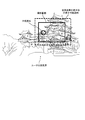
- the predetermined size is, for example, an area, which is about half or 1/3 of the displayable range of the display unit 102. If the determination here is negative, that is, if the imaging range of the imaging device 20 is greater than or equal to a predetermined size, the process proceeds to step S43D, and the control unit 111 displays the imaging range of the imaging device 20 on the display unit 102. Display above. For example, within the displayable range of the display unit 102, the shooting range of the imaging device 20 is displayed as shown in FIG.
- step S44 the control unit 111 detects the user's line of sight via the line-of-sight detection unit 108.
- the line-of-sight detection unit 108 detects which position in the imaging range of the imaging device 20 in FIG.
- the circle area is detected as a place where the user is gazing.
- the control unit 111 determines whether or not half-press information has been received from the imaging device 20 side. If the determination here is negative, the control unit 111 returns to step S43B.
- step S43E the control unit 111 displays a live view image on the display unit 102 as shown in FIG.
- step S ⁇ b> 44 the control unit 111 detects the user's line of sight via the line-of-sight detection unit 108.
- the line-of-sight detection unit 108 detects which position of the live view image in FIG.
- the circle area is detected as a place where the user is gazing.
- step S43E the control unit 111 displays the live view image on the display unit 102 as shown in FIG. In this case, the live view image is in an enlarged display state.
- step S ⁇ b> 44 the control unit 111 detects the user's line of sight via the line-of-sight detection unit 108. In this case, the line-of-sight detection unit 108 detects which position of the live view image in FIG.
- the circle area is detected as a place where the user is gazing.
- FIG. 19 Other processes in FIG. 19 are the same as those in the first embodiment (FIG. 6).
- the same effect as that of the first embodiment can be obtained.
- the shooting range of the imaging device 20 can be displayed in an easily viewable manner, the user can easily recognize the shooting range.
- the shooting range of the imaging apparatus 20 when the shooting range of the imaging apparatus 20 is smaller than a predetermined size as shown in FIG. 22A, the live view image is displayed on the display unit 102 as shown in FIG.
- the shooting range of the imaging device 20 may be displayed on the display unit 102.
- the present invention is not limited to this.
- a contact lens type display is provided.
- the device may be worn by the user.
- the display range of the display device can almost cover the real field of view of the user. Therefore, as shown in FIG. 23, when the imaging range of the imaging device 20 is wide (the imaging range is, for example, a focal point in 35 mm format conversion). Even in the case where the image is captured by an imaging device equipped with a lens having a distance of 21 mm, the imaging range of the imaging device 20 can be displayed. Even in the case of FIG. 23, when the shooting range of the imaging device 20 is smaller than a predetermined size, the live view image may be enlarged and the line of sight may be detected as in FIG.
- an image captured by the imaging unit 101 of the mounting apparatus 10 is displayed on the display unit 102, and the position of the user among the images displayed on the display unit 102 is displayed. It may be detected whether or not the user has watched.
- two display units 102 are provided corresponding to the right eye and the left eye, one of which is a live view image of the imaging device 20, and the other is an imaging unit of the mounting device 10.
- the image captured at 101 may be displayed.
- line-of-sight detection (S44) it may be detected which position of the image the user gazes with either one eye (with one eye closed).
- the case where the live view image of the imaging device 20 is transmitted to the mounting device 10 and the mounting device 10 specifies and displays the shooting range of the imaging device 20 based on the live view image will be described.
- information on the focal length of the imaging device 20 may be transmitted to the mounting device 10, and the shooting range of the imaging device 20 may be specified and displayed based on the focal length information received by the mounting device 10.
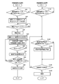
- step S160 the control unit 211 of the imaging device 20 stands by until a user requests to set the cooperative shooting mode in step S160.
- step S60 the control unit 111 of the mounting apparatus 10 stands by until a user requests to set the cooperative shooting mode.
- the process proceeds to steps S162 and S62.
- step S162 the control unit 211 starts transmitting a live view image to the control unit 111 of the mounting apparatus 10.
- the control unit 111 stands by until a live view image is received from the imaging device 20 side in step S 62, so that the process proceeds to step S 64 when step S 162 is executed on the imaging device 20 side. Transition.
- step S64 the control unit 111 starts displaying the live view image on the display unit 102, and displays a cooperative shooting mode start message on the display unit 102 in the next step S66.
- step S66 the order of step S64 and step S66 may be reversed.
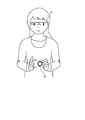
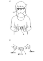
- the user who sees the cooperative shooting mode start message starts an operation (reciprocating operation) of changing the imaging direction of the imaging device 20 as illustrated in FIG. Since the live view image is continuously transmitted from the imaging device 20 side, the live view image on the display unit 102 is continuously updated while the user changes the imaging direction of the imaging device 20.
- FIG. 26A and FIG. 26B show an example of a live view image displayed on the display unit 102 while the user changes the imaging direction.
- step S68 the control unit 111 stands by until a predetermined operation by the user is detected.
- the predetermined operation here is a predetermined operation performed when the user determines to perform imaging, and is assumed to be a predetermined number of blinks, for example. It is assumed that the user sees the live view image and performs blinking a predetermined number of times at the timing when the composition is desired to be captured (for example, when the composition is as shown in FIG. 26B).
- step S70 the control unit 111 transmits an imaging instruction to the control unit 211 of the imaging device 20 via the communication unit 110.
- the process of FIG. 24 by the control unit 111 ends.
- step S162 the imaging device 20 stands by until an imaging instruction is received from the mounting device 10 side in step S164. Accordingly, the control unit 211 proceeds to step S166 at the timing when the process of step S70 described above is executed on the mounting device 10 side.
- step S166 the control unit 211 acquires from the azimuth sensor 208 the imaging direction of the imaging device 20 at the timing when the imaging instruction is received.
- step S168 the detection result (imaging direction) is acquired from the direction sensor 208, and the process waits until the current imaging direction becomes the imaging direction imaged in step S166. If the time between step S166 and step S168 is short, the determination of step S168 is affirmed immediately after step S166, but the time between step S166 and step S168 is long, or the user takes the imaging device 20. If the speed at which the camera is moved is fast, the determination in step S168 is affirmed after step S166, when the imaging direction of the imaging device 20 again matches the imaging direction acquired in step S166.
- step S168 the process proceeds to step S170, and the control unit 211 instructs the imaging unit 201 to capture an image. Accordingly, the imaging unit 201 can capture an image that the user wants to capture as illustrated in FIG. Thus, the entire process of FIG. 24 by the control unit 211 is completed.
- control units 111 and 211 may repeat the processing of FIG. 24, or may repeat the processing after step S64 and the processing after step S164 until the cooperative shooting mode is canceled.
- the display unit 102 displays the live view image captured by the imaging unit 201 of the imaging device 20 in the vicinity of the user's eyes, and the control unit 111 Based on the imaging result of the pupil imaging unit 107, the user's specific action (for example, a predetermined number of blinks) is detected. And the control part 111 transmits the information (imaging instruction
- imaging instruction indication
- the imaging device 20 can capture an image in an appropriate imaging direction. Accordingly, the user can take an image in an appropriate imaging direction without performing an operation of pressing the release switch 203A while looking at the display unit 202 of the imaging device 20, and thus it is difficult to see the display unit 202, When it is difficult to press the release switch 203A, the usability of the imaging device 20 can be improved.
- the imaging device 20 of the third embodiment captures an image desired by the user by performing imaging based on information according to the timing at which the user's specific operation transmitted from the mounting device 10 is detected. An image can be taken.
- the display unit 202 does not have to be provided in the imaging apparatus 20, and therefore it is possible to reduce the manufacturing cost, the number of parts, and the power consumption of the imaging apparatus 20. .
- the control unit 111 transmits an imaging instruction to the control unit 211 when detecting a user's predetermined operation that changes the imaging direction of the imaging device 20 .
- the control unit 111 transmits an imaging instruction to the control unit 211 when detecting that a user who changes the imaging magnification of the imaging device 20 between tele and wide has performed a predetermined operation. You may make it do.
- the imaging device 20 performs imaging at an appropriate imaging magnification. It will be.
- control unit 111 detects a predetermined number of blinks as the user's predetermined operation.
- control unit 111 is not limited to this and detects other eye operations. May be. As other eye movements, changes in the pupil and the like can be employed.
- the control unit 111 may detect an operation other than the eyes (for example, an input operation to the operation unit 103).
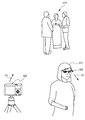
- a holding device 40 such as a tripod or a pan head
- a drive mechanism 42 that can change the imaging direction of the imaging device 20 within a predetermined angle range
- the user can easily capture an image in the desired imaging direction by performing a predetermined operation when the imaging device 20 captures the desired imaging direction. It becomes possible to do.
- a configuration including the server 30 as shown in FIG. 16 may be adopted as in the first embodiment.
- the control unit 34 of the server 30 may perform part of the processing of FIG.
- step S180 the control unit 211 of the imaging device 20 stands by until a user requests to set the cooperative shooting mode.
- step S80 the control unit 111 of the mounting apparatus 10 stands by until a user requests to set the cooperative shooting mode.
- the process proceeds to steps S182 and S82.
- step S ⁇ b> 82 the control unit 111 displays a message on the display unit 102 so as to see the center of the range to be photographed. For example, the display unit 102 displays a message such as “Please watch the part you want to shoot for a certain period of time”.
- step S84 the control unit 111 stands by until the user's line of sight is determined based on the image of the pupil imaging unit 107.
- the process proceeds to step S ⁇ b> 86, and the control unit 111 detects the user's line of sight via the pupil imaging unit 107 and the line of sight detection unit 108.
- step S88 the control unit 111 displays the center of the range that the user wants to photograph on the display unit 102 based on the line-of-sight detection result in step S86.
- the center of the range that the user wants to shoot is displayed with a cross mark.
- the cross mark is displayed so as to overlap (superimpose) on the scenery the user is viewing.
- the control unit 111 may start over from step S82.
- step S90 the control unit 111 requests the imaging device 20 to transmit an imageable range.
- step S ⁇ b> 180 in the imaging device 20 the control unit 211 determines that an imaging request is transmitted from the imaging device 20 (until step S ⁇ b> 182 is affirmed) or an imaging instruction is received. Until it is transmitted (until step S186 is affirmed). Therefore, the determination of step S182 is affirmed at the timing when the process of step S90 is performed on the mounting device 10, and the process proceeds to step S184.
- step S184 the control unit 211 transmits the imageable range of the imaging unit 201. Specifically, the live view image captured by the imaging unit 201 is transmitted to the control unit 111 of the mounting apparatus 10.
- step S92 By the way, on the mounting device 10 side, after step S90, in step S92, it is on standby until an imageable range is received. Accordingly, the control unit 111 proceeds to step S94 at the timing when the process of step S184 is executed on the imaging device 20 side.
- the control unit 111 displays the imageable range. Specifically, the control unit 111 acquires an image (field-of-view image) captured by the imaging unit 101, and compares the image with the imageable range (live view image) received in step S92. Then, it is calculated which range of the user's field of view the imageable range corresponds to. Then, the control unit 111 displays the calculated range frame on the display unit 102 as an imageable range. In this case, as shown in FIG. 29B, the display unit 102 displays the center (cross mark) of the range desired to be captured displayed in step S88, a frame indicating the imageable range, and the center of the imageable range ( Are displayed so as to overlap (superimpose) on the scenery the user is viewing.
- the user looks at the display on the display unit 102 (the display in FIG. 29B), so that the center (cross mark) of the range to be photographed matches the center ( ⁇ mark) of the imageable range.
- the imaging direction can be changed.
- step S94 the control unit 111 proceeds to step S96, and determines whether the shootable range matches the center of the range to be shot, that is, whether the cross mark and the X mark match. If the determination is negative, the process returns to step S90, and the processing and determination of steps S90 to S96 are repeated until the determination of step S96 is affirmed. If the user changes the imaging direction of the imaging device 20 during the repetition of steps S90 to S96, the imageable range moves on the display unit 102. If the user changes the imaging magnification of the imaging device 20, the size of the imageable range on the display unit 102 is changed.
- step S96 If the user changes the imaging direction of the imaging device 20 and the center of the imageable range coincides with the center of the range to be photographed as shown in FIG. 30A, the determination in step S96 is affirmed.
- the control unit 111 proceeds to step S98. If transfering it to step S98, the control part 111 will transmit an imaging instruction
- step S186 the determination in step S186 is affirmed and the process proceeds to step S188.
- the control unit 111 performs imaging using the imaging unit 101.
- the imaging unit 101 can capture an image in a range that the user wants to capture, as shown in FIG.
- imaging is performed when the range to be captured and the imageable range match is described.
- the present invention is not limited thereto, and the control unit 211 performs a case where the user performs a predetermined operation.
- imaging may be performed when the release switch 203A is pressed, when the operation unit 103 is operated, or when blinking a predetermined number of times.
- the control unit 111 acquires information on the imaging region of the imaging device (capturable range) and information on the user's line of sight (range where the user wants to shoot), Information acquired via the display unit 102 is displayed in the vicinity of the user's eyes. Thereby, the user can perform imaging using the imaging device 20 after confirming the imageable range and the range to be captured and changing the imaging direction of the imaging device 20 as necessary. Thereby, the user can easily capture an image desired by the user even in a situation where it is difficult to view the display unit 202.
- the imaging device 20 of the fourth embodiment can capture an image desired by the user by performing imaging based on the imaging instruction transmitted from the mounting device 10.
- the display unit 202 does not have to be provided in the imaging device 20, and therefore it is possible to reduce the manufacturing cost, the number of parts, the power consumption, and the like of the imaging device 20. .
- control unit 111 is based on the information on the imaging region of the imaging device 20 and the information on the user's line of sight, that is, when the imageable range matches the range to be captured.
- information for controlling the imaging device 20 is transmitted to the imaging device 20 via the communication unit 110. Accordingly, the user can take an image desired by the user without performing an operation such as pressing the release button.
- the center of the range to be photographed and the frame and center of the imageable range are displayed on the display unit 102.
- the present invention is not limited to this.
- an image obtained by adding (combining) the center of the range to be photographed, the frame and the center of the imageable range to the image captured by the imaging unit 101 of the mounting apparatus 10 may be displayed on the display unit 102. Even if it does in this way, the effect similar to the said 4th Embodiment can be acquired.
- control unit 111 may display the direction and amount of movement of the imaging device 20 by the user on the display unit 102 using an arrow (vector) or the like. Thereby, the user can adjust the imaging direction of the imaging device 20 intuitively.
- the present invention is not limited to this.
- a holding device 40 such as a tripod or a pan head
- the holding device 40 changes the imaging direction of the imaging device 20 using the drive mechanism 42 so that the center of the range to be photographed in FIG. You just have to do it. Thereby, it is possible to automatically capture an image desired by the user.
- a configuration including the server 30 as shown in FIG. 16 may be adopted as in the first embodiment.
- the control unit 34 of the server 30 may perform part of the processing of FIG. Further, the control unit 34 of the server 30 acquires the range that the user wants to shoot from the mounting device 10, acquires the imageable range from the imaging device 20, compares these ranges, and compares the comparison results with the mounting device 10 or You may make it output to the imaging device 20 and the holding
- the imaging apparatus 20 includes the operation unit 203 .
- the present invention is not limited to this, and in particular, in the third and fourth embodiments, the operation unit 203 is provided. It does not have to be.
- the present invention is not limited to this.
- the person is photographed while talking with the person. You may use for.
- the image can be taken without holding the imaging device 20 in front of the face, it is possible to take an image of a natural expression of the person who is talking.
- the imaging unit 101, the display unit 102, and the pupil imaging unit 107 of the mounting device 10 are provided on the frame 120, and other functions are provided to a smartphone, a mobile phone, a wristwatch-type terminal, or the like. Also good.
- FIG. 31 is a block diagram illustrating a configuration of an imaging system 500 according to the fifth embodiment.
- the imaging system 500 includes a wearable device 300 and an imaging device 400.
- the wearable device 300 is a glasses-type terminal that the user wears on the face. As shown in FIG. 31, the wearable device 300 includes an imaging unit 301, a display unit 302, an operation unit 303, a microphone 304, a direction sensor 305, a speaker 306, a storage unit 307, and a communication unit 308. And a control unit 309.
- FIG. 32A shows the wearable device 300 in a perspective view. As shown in FIG. 32A, the wearable device 300 includes a glasses-type frame 320. The configuration of the wearable device 300 illustrated in FIG. 31 and not illustrated in FIG. 32A is provided inside the frame 320 or a part of the frame 320.
- the imaging unit 301 includes a lens, an imaging element, an image processing unit, and the like, and captures still images and moving images.
- the imaging unit 301 is provided in the vicinity of the end of the frame 320 (in the vicinity of the user's right eye) as shown in FIG. For this reason, when the user wears the wearable device 300, it is possible to capture an image in the direction in which the user is facing (looking at).
- the display unit 302 includes a projector provided in or near the frame 320, and a prism for guiding a projection image from the projector to the eyes of the user.
- the display unit 302 displays various information under the control of the control unit 309.
- the operation unit 303 is a touch pad provided on the frame 320, detects the movement of the user's finger, receives an operation from the user, and transmits the received operation information to the control unit 309. Details of the imaging unit 301, the display unit 302, the operation unit 303, and the like are also disclosed in, for example, US Published Patent No. 2013/0044042.
- the microphone 304 is provided in the frame 320 and collects voices uttered by the user.
- the voice collected by the microphone 304 is voice recognized by a voice recognition unit (not shown), and the voice recognition result is transmitted to the control unit 309.
- the control unit 309 executes processing (for example, command execution processing) based on the voice recognition result. Note that the control unit 309 may execute voice recognition.
- the direction sensor 305 detects the direction in which the wearable device 300 is facing, for example, based on geomagnetism.
- the orientation sensor 305 detects the direction in which the imaging unit 301 of the wearable device 300 is facing, that is, the direction in which the user wearing the wearable device 300 is facing (looking at).
- the direction sensor 305 outputs the detection result to the control unit 309.
- the speaker 306 is an audio output device that is provided in the frame 320 and outputs audio under the control of the control unit 309, for example.
- a speaker having directivity and capable of providing audio information mainly toward the ear of the user wearing the wearable device 300 can be employed. .
- the storage unit 307 is, for example, a nonvolatile semiconductor memory such as a flash memory, and stores image data captured by the imaging unit 301, display data displayed on the display unit 302, and the like.
- the communication unit 308 performs wireless communication (communication using a mobile phone line, a wireless LAN, or the like) with other devices.
- the communication unit 308 performs communication with the imaging device 400.
- the communication unit 308 may perform near field communication with other devices such as Bluetooth (registered trademark), RFID, and TransferJet (registered trademark).
- the communication unit 308 may use human body communication that communicates via a user (human body) for communication with other devices.
- human body communication there is a current system that transmits information by passing a weak current through the human body and modulates the current, and an electric field system that transmits information by modulating the electric field induced on the surface of the human body. It is also possible to use this method.
- the control unit 309 controls the entire wearable device 300 in an integrated manner.
- the control unit 309 includes a CPU, RAM, ROM, and the like. Details of processing executed by the control unit 309 will be described later.
- the imaging device 400 is, for example, a camera, a mobile phone having an imaging function, a smartphone, a tablet terminal, or the like. In the present embodiment, the image capturing apparatus 400 will be described as a camera. In FIG. 32B, the imaging device 400 is shown in a perspective view. The imaging device 400 may be any of a single-lens reflex camera, a mirrorless camera, and a compact camera. In the present embodiment, the imaging device 400 is assumed to be a compact camera as shown in FIG. In addition, the imaging apparatus 400 includes a “normal shooting mode” in which imaging is performed by the imaging apparatus 400 alone without cooperation with the wearable device 300 and a “cooperative shooting mode” in which imaging is performed in cooperation with the wearable device 300. In the fifth embodiment, when the imaging apparatus 400 is in the “cooperative shooting mode”, a through image captured by the imaging unit 401 can be transmitted to the wearable device 300. In addition, the imaging apparatus 400 can automatically image a subject not only based on a user operation.
- the imaging apparatus 400 includes an imaging unit 401, a display unit 402, an operation unit 403, a microphone 404, a speaker 405, a storage unit 406, a communication unit 407, an orientation sensor 408, and a pressure sensor. 409, a line-of-sight detection unit 410, an electrostatic sensor 411, an acceleration sensor 412, and a control unit 413.
- the image capturing unit 401 includes a lens, an image sensor, an image processing unit, and the like, and captures still images and moving images.
- the display unit 402 is, for example, an LCD, and is provided on the surface of the imaging unit 401 opposite to the lens.
- the display unit 402 displays various setting information for the imaging apparatus 400, operation menus, icons, and the like for operating the imaging apparatus 400. Further, the display unit 402 displays a through image (live view image) captured by the imaging unit 401 and a still image or a moving image recorded in the storage unit 406 described later.
- the operation unit 403 includes, for example, various switches including a release switch 403A illustrated in FIG. 32B, a touch panel provided on the same surface as the display unit 402, and the like.
- the release switch 403A is operated (pressed) by the user when instructing to capture a still image, for example.
- the touch panel is provided on the display unit 402 or incorporated in the display unit 402, for example, detects a user's touch operation on the surface of the display unit 402, and accepts various information inputs.
- the microphone 404 is a voice input device that is provided on the opposite surface of the display unit 402 and inputs a voice when a still image or a moving image is taken.
- the speaker 405 is an audio output device that outputs audio based on audio data associated with still image data or moving image data.
- the speaker 405 is provided on the same surface as the display unit 402, for example.
- the storage unit 406 includes, for example, a connector connected to an SD card that is a storage medium that can be attached to and detached from the imaging apparatus 400, and stores still image data and moving image data in the SD card.
- the communication unit 407 performs wireless communication (communication using a mobile phone line or a wireless LAN) with other devices. In the present embodiment, the communication unit 407 performs communication with the wearable device 300. As described above, proximity communication or human body communication may be used as communication of the communication unit 407.
- the direction sensor 408 detects the direction in which the imaging unit 401 is directed based on, for example, geomagnetism, and outputs the detection result to the control unit 413.
- the pressure sensor 409 is provided in a portion (hereinafter referred to as a grip portion) that is held by a user when the user performs imaging using the imaging device 400, and is applied to the grip portion.
- the pressure is detected and the detected value is output to the control unit 413.
- the control unit 413 determines whether the user has gripped the grip portion based on the detection value of the pressure sensor 409.
- the line-of-sight detection unit 410 includes, for example, an infrared LED (Laser Emitting Diode) and an infrared camera, illuminates the face of the subject with the infrared LED, and copies the eye of the subject with the infrared camera.
- the line of sight of the subject is detected based on the position.
- the line-of-sight detection unit 410 is provided on the surface opposite to the display unit 402, that is, the same surface as the microphone 404. Details of eye gaze detection are also disclosed in Japanese Patent Application Laid-Open No. 2012-115505.
- the electrostatic sensor 411 is provided in the release switch 403 ⁇ / b> A, detects a change in capacitance, and outputs a detection result to the control unit 413. Based on the detection result of the electrostatic sensor 411, the control unit 413 determines whether or not the user places a finger on the release switch 403A.
- the acceleration sensor 412 detects the acceleration of the imaging device 400 and outputs the detected value to the control unit 413.
- the acceleration sensor 412 a piezoelectric element, a strain gauge, or the like can be used.
- the number of axes of the acceleration sensor 412 any one of the first to third axes may be appropriately selected, and the number can be arbitrarily set.
- the control unit 413 determines whether or not the user has held the imaging apparatus 400 in a certain posture for a predetermined time, that is, whether or not the composition of imaging has been determined.
- the control unit 413 controls the entire imaging apparatus 400 in an integrated manner.
- the control unit 413 includes a CPU, RAM, ROM, and the like.
- FIG. 33A is a flowchart illustrating an example of processing executed by the imaging apparatus 400
- FIG. 33B is a flowchart illustrating an example of processing executed by the wearable device 300.
- the processes in FIGS. 33A and 33B are started when the imaging device 400 and the wearable device 300 are turned on or communication is established between the imaging device 400 and the wearable device 300.
- the imaging apparatus 400 starts the operation in the “normal imaging mode” when the power is turned on, and the imaging unit 401 starts imaging the through image.
- the captured through image is displayed on the display unit 402 of the imaging apparatus 400.
- the wearable device 300 that communicates with the imaging device 400 is paired in advance, for example, by bringing the wearable device 300 and the imaging device 400 into contact with each other or in close proximity to each other. Assume that the wearable device 300 holds the device. In this case, pairing may be performed by establishing the above-described proximity communication or human body communication. When one of the power of the wearable device 300 and the imaging device 400 is off, the power of the device whose power is off may be turned on due to the establishment of proximity communication or human body communication. In the present embodiment, pairing refers to a state in which cooperative processing between a plurality of devices can be executed.
- step S210 the control unit 413 determines whether or not a user's predetermined operation has been detected. For example, the control unit 413 determines whether the user has set the “cooperative shooting mode” for the imaging apparatus 400 using the touch panel provided in the operation unit 403. If the determination here is affirmed, the control unit 413 proceeds to step S215. If the determination is negative, the control unit 413 proceeds to step S211.
- the control unit 413 determines whether or not the user has taken an operation related to looking-ahead photography (Norook photography) in which the subject is imaged without looking at the subject. Specifically, in step S ⁇ b> 211, the control unit 413 first, in step S ⁇ b> 211, the direction of the wearable device 300 input from the direction sensor 305 of the wearable device 300 and the imaging direction of the imaging unit 401 input from the direction sensor 408. Whether or not is different. That is, in step S211, the control unit 413 causes the user to face the imaging unit 401 of the imaging apparatus 400 (the optical axis direction of the lens of the imaging unit 401) and the user's direction (the user's line-of-sight direction).
- the control unit 413 calculates an angle formed by the direction in which the wearable device 300 faces and the imaging direction of the imaging unit 401. If the angle is equal to or greater than a predetermined value (for example, 5 degrees), the wearable device. It is determined that the direction in which 300 is facing and the imaging direction of the imaging unit 401 are different.
- a predetermined value for example, 5 degrees
- the control unit 413 returns to step S210.
- the angle formed by the imaging direction D1 of the imaging unit 401 and the direction D2 in which the wearable device 300 faces is equal to or greater than a predetermined value
- the control unit 413 proceeds to step S212.
- the control unit 413 determines whether a user's predetermined operation is detected. For example, the control unit 413 determines whether or not the user has performed an operation related to imaging based on at least one output value of the pressure sensor 409, the electrostatic sensor 411, and the acceleration sensor 412. Specifically, the control unit 413 determines whether the user holds the grip portion of the imaging device 400 based on the output value of the pressure sensor 409. Further, the control unit 413 determines whether or not the user has put a finger on the release switch 403A based on the output value of the electrostatic sensor 411.
- the control unit 413 determines whether or not the user has held the imaging apparatus 400 in a certain posture for a predetermined time (for example, 3 seconds), that is, whether the imaging composition has been determined. Judge whether or not.
- the control unit 413 directs the image capturing unit 401 of the image capturing apparatus 400 to a direction different from the direction in which the user is facing (step S211 / YES) and takes an operation related to image capturing (step S212 / YES). , It is determined that the user will take a look away and the process proceeds to step S215.
- step S215 the control unit 413 shifts the imaging apparatus 400 to the “cooperative shooting mode”.
- the communication unit 407 starts transmitting the through image captured by the imaging unit 401 to the wearable device 300 in step S216.
- the control unit 309 of the wearable device 300 determines whether or not a through image has been received from the imaging device 400 in step S232 of FIG.
- the determination in step S232 is affirmed, and the control unit 309 proceeds to step S240, and the received through image is displayed on the display unit. 302, and the process returns to step S232.
- the user U10 can perform imaging while confirming the through image displayed on the display unit 302 without facing his face to the subject O10 or the imaging device 400. it can.
- step S234 determines whether or not a through image transmission request has been received from the user. For example, the control unit 309 determines whether or not the user has input a predetermined voice command by performing a predetermined operation (for example, tapping) on the operation unit 303 or by pronounced “shoot away” to the microphone 304. Determine whether. If the determination is negative, the control unit 309 returns to step S232, but if the determination is positive, the control unit 309 proceeds to step S236.
- a predetermined voice command for example, tapping
- control unit 309 requests the imaging device 400 to transmit a through image. After requesting transmission of a through image, the control unit 309 waits until a through image is received in step S238.
- step S212 of FIG. 33A when the control unit 413 does not detect the user's predetermined operation (step S212 / NO), the control unit 413 proceeds to step S214, and the through-type image 300 is transferred from the wearable device 300. It is determined whether a transmission request is received. When judgment here is denied, it returns to step S210.
- the control unit 309 of the wearable device 300 requests transmission of a through image in step S236 of FIG. 33B
- the determination in step S214 is affirmed, and the control unit 413 determines that the above-described steps S215 and S216 are performed. Execute the process.
- step S240 the control unit 309 of the wearable device 300 is on standby until a through image is received in step S238 of FIG. 33B, so that the process of step S216 of FIG. In step S240, the received through image is displayed on the display unit 302. After step S240 ends, the process returns to step S232. The process of FIG. 33B is repeated until the power of the wearable device 300 is turned off.
- control unit 413 of the imaging apparatus 400 determines whether or not the state of the subject is in a predetermined state in step S218 of FIG. In the present embodiment, the control unit 413 determines whether or not the subject is not conscious of the imaging device 400. For example, the control unit 413 determines, based on the detection result of the line-of-sight detection unit 410, whether the line of sight of the subject is not facing the imaging device 400 for a certain period of time (for example, 10 seconds). The fact that the line of sight of the subject is not facing the imaging device 400 is because the subject is not conscious of the imaging device 400.
- step S220 the control unit 413 proceeds to step S220 and automatically performs imaging of the subject by the imaging unit 401.
- the control unit 413 proceeds to step S220 and automatically performs imaging of the subject by the imaging unit 401.
- the user may manually perform imaging by operating the release switch 403A while confirming the through image displayed on the display unit 302 of the wearable device 300.
- step S ⁇ b> 222 the control unit 413 determines whether an instruction to end the “cooperative shooting mode” is received from the user via the operation unit 403. If the determination is negative, the process returns to step S218. If the determination is positive, the control unit 413 proceeds to step S224.
- step S224 the control unit 413 shifts the imaging apparatus 400 to the “normal shooting mode” and returns to step S210.
- the communication unit 407 ends transmission of the through image to the wearable device 300. The process of FIG. 33A is repeated until the power of the imaging apparatus 400 is turned off.
- the user sets the “cooperative shooting mode” by operating the imaging device 400 or the wearable device 300 (when the user intends to look away), or the user does not look at the direction of the subject.
- the imaging device 400 is pointed in the direction of the subject and an operation related to imaging is performed (when the user is likely to take a look away)
- the through image captured by the imaging unit 401 is transmitted to the wearable device 300, In other cases, the through image is not transmitted to the wearable device 300. Accordingly, a through image captured by the imaging unit 401 can be displayed on the display unit 302 of the wearable device 300 at an appropriate timing when the user performs looking away.
- the imaging apparatus 400 includes the communication unit 407 that can transmit the through image captured by the imaging unit 401 to the wearable device 300, and the communication unit 407. Even when communication with the wearable device 300 is established and the imaging unit 401 captures a through image, the control unit 413 waits for transmission of the through image captured by the image capturing unit 401 to the wearable device 300. When the wearable device 300 and the imaging device 400 cooperate, a through image can be transmitted from the imaging device 400 to the wearable device 300 at an appropriate timing. Thus, by always displaying the through image captured by the imaging unit 401 on the display unit 302 of the wearable device 300, it is possible to prevent the user from feeling uncomfortable with the through image, and the power consumption of the wearable device 300. The user convenience can be improved.
- the imaging apparatus 400 includes a pressure sensor 409, an electrostatic sensor 411, and an acceleration sensor 412 to detect a user operation or operation related to imaging
- the control unit 413 includes: When a user's predetermined operation or operation is detected based on the output value of each sensor, a through image is transmitted to the wearable device 300. Specifically, the control unit 413 directs the image capturing unit 401 of the image capturing apparatus 400 in a direction different from the direction in which the user is facing, the pressure sensor 409, the electrostatic sensor 411, and the acceleration.
- an operation in which the user grips the grip portion of the imaging device 400 Based on the output value of the sensor 412, an operation in which the user grips the grip portion of the imaging device 400, an operation in which the user places a finger on the release switch 403A, and an operation in which the user holds the imaging device 400 in a certain posture for a predetermined time.
- the through image is transmitted to the wearable device 300 via the communication unit 407. Accordingly, a through image can be displayed on the display unit 302 of the wearable device 300 when the user tries to take a look away. As a result, the user can take an image while confirming the through image displayed on the display unit 302 without having to face the subject or the imaging apparatus 400.
- control unit 413 transmits a through image when an operation for requesting transmission of a through image is performed in the wearable device 300, so that the wearing is performed at a timing desired by the user.
- a through image can be displayed on the display unit 302 of the mold apparatus 300.
- control unit 413 automatically executes imaging by the imaging unit 401 when the line of sight of the subject is not directed to the imaging device 400 based on the detection result of the visual line detection unit 410.
- imaging can be performed at a timing when the subject is not conscious of the imaging apparatus 400 and there is a high possibility that the subject has a natural expression or gesture, and the natural expression or gesture of the subject can be captured. .
- the control unit 413 of the imaging apparatus 400 has the user pointing the imaging unit 401 of the imaging apparatus 400 in a direction different from the direction in which the user is facing, and the user
- the through image may be transmitted to the wearable device 300 at the timing when the release switch 403A is pressed halfway and the imaging unit 401 performs the release operation. Accordingly, a through image can be displayed on the display unit 302 of the wearable device 300 when the user tries to take a look away.
- the control unit 413 uses the imaging unit 401 when the smile detection unit detects a smile. Imaging may be performed automatically. As a result, it is possible to capture a natural expression or gesture of the subject.
- the line-of-sight detection unit 410 illuminates the subject's face with an infrared LED and projects the subject's eyes with an infrared camera, so that the subject is based on the position of the pupil relative to the position of corneal reflection.
- the present invention is not limited to this.
- the line-of-sight detection unit 410 may detect the line of sight of the subject based on the position of the eyeball of the subject included in the through image captured by the imaging unit 401.
- the control unit 413 determines whether the direction in which the imaging unit 401 is facing and the direction in which the user is facing are different from the direction sensor 305 and the direction sensor 408.
- the determination is made based on the detected value.
- the control unit 413 compares the through image captured by the imaging unit 401 with the image captured by the imaging unit 301 of the wearable device 300 so that the imaging unit 401 It may be determined whether the direction in which the user is facing is different from the direction in which the user is facing. In this case, the control unit 413 may determine based on whether or not the main subject included in the through image captured by the imaging unit 401 is included in the image captured by the imaging unit 301 of the wearable device 300.
- control unit 413 performs the processing and determination in steps S218 and S220 in the cooperative shooting mode.
- present invention is not limited thereto, and the processing and determination in steps S218 and S220 are performed. It may be omitted.
- the through image when a through image is transmitted from the imaging device 400 side to the wearable device 300 side, the through image may not be displayed on the display unit 402 of the imaging device 400. As a result, power consumption can be reduced, and the subject can be prevented from being conscious of being imaged by the imaging device 400.
- the configuration of the imaging system according to the sixth embodiment is the same as or equivalent to the configuration illustrated in FIG. 31 of the fifth embodiment, illustration and description thereof are omitted.
- the imaging apparatus 400 when the imaging apparatus 400 is in the “cooperative shooting mode”, a through image captured by the imaging unit 401 is transmitted to the wearable device 300 as in the fifth embodiment. This makes it possible to automatically image a subject.
- the setting of the imaging unit 401 is changed in order to increase the probability of imaging a natural expression or gesture of the subject.
- FIG. 35 is a flowchart illustrating processing executed by the imaging apparatus 400. Also in the sixth embodiment, the processing of FIG. 35 is started when the imaging apparatus 400 and the wearable device 300 are turned on and communication is established between the imaging device 400 and the wearable device 300. Shall. Note that the imaging apparatus 400 starts to operate in the “normal imaging mode” when the power is turned on, and the imaging unit 401 starts to capture a through image and display it on the display unit 402.
- the wearable device 300 that communicates with the imaging device 400 is paired in advance, for example, by bringing the wearable device 300 and the imaging device 400 into contact with each other or in close proximity to each other. Assume that the wearable device 300 holds the device.
- step S252 the control unit 413 inputs, from the direction sensor 305 of the wearable device 300, the direction in which the wearable device 300 is facing (direction D2 in the example of FIG. 34). Further, in the subsequent step S254, the control unit 413 inputs the imaging direction of the imaging unit 401 (direction D1 in the example of FIG. 34) from the orientation sensor 408. Note that the processing order of steps S252 and S254 may be reversed.
- step S256 the control unit 413 determines whether or not the direction in which the wearable device 300 faces and the imaging direction of the imaging unit 401 are different as in step S211 of FIG. If the determination is negative, the control unit 413 returns to step S252 ("normal shooting mode" is maintained), but if the determination is positive, the control unit 413 proceeds to step S260.
- step S260 the control unit 413 shifts the imaging apparatus 400 to the “cooperative shooting mode”.
- step S262 the communication unit 407 starts transmitting the through image captured by the imaging unit 401 to the wearable device 300.
- the wearable device 300 that has received the through image displays the through image on the display unit 302.
- the user waits for the imaging timing while confirming the through image captured by the imaging unit 401 on the display unit 302 without directly viewing the subject or confirming the display unit 402 of the imaging device 400. Can do.
- the control unit 413 changes the setting of the imaging unit 401.
- the control unit 413 first turns off the display of the display unit 402. Since the user can confirm the through image on the display unit 302 of the wearable device 300, the power consumption of the imaging device 400 can be reduced by turning off the display of the display unit 402 of the imaging device 400.
- the control unit 413 increases the strength of camera shake correction of the camera shake correction function. In the “cooperative shooting mode”, as shown in FIG. 34, since it is highly likely that the user will hold the camera with one hand to take an image, it is difficult to cause camera shake by increasing the strength of camera shake correction. Can do.
- control unit 413 sets a “silent mode” that can reduce the sound generated when the imaging unit 401 captures an image. As a result, it is possible to suppress the sound generated at the time of imaging, so that it is possible not to be conscious of the subject being imaged, and it is possible to image the natural expression and gesture of the subject. Further, the control unit 413 starts capturing a moving image by the imaging unit 401. As a result, the possibility of missing a decisive moment of the subject is reduced, and a still image can be extracted from the recorded moving image. Note that the imaging apparatus 400 of the present embodiment is capable of capturing still images even during moving image capturing.
- step S264 the control unit 413 executes the processes of steps S266 to S270 in the same manner as steps S218 to S222 of FIG. 33A, and receives an instruction to end the “cooperative shooting mode” from the user. In step, the process proceeds to step S272.
- step S272 the control unit 413 shifts the imaging apparatus 400 to the “normal shooting mode” and returns to step S252.
- the communication unit 407 ends the transmission of the through image to the wearable device 300. The process of FIG. 35 is repeated until the power of the imaging apparatus 400 is turned off.
- the setting of the imaging unit 401 is set to look away.
- the setting is automatically changed to a setting suitable for shooting. Accordingly, the user does not need to manually change the setting of the imaging unit 401, and can perform the looking-ahead shooting using the imaging device 400 that is set to be suitable for the looking-ahead shooting.
- the control unit 413 of the imaging apparatus 400 includes the imaging direction of the imaging unit 401 and the direction in which the wearable device 300 worn by the user is facing. Are input via the communication units 308 and 407, and the imaging unit 401 is controlled based on the imaging direction of the imaging unit 401 and the direction in which the wearable device 300 faces, so the imaging device 400 and the wearable device 300 are controlled. Can be controlled appropriately, and the convenience of the user is improved.
- the imaging apparatus 400 includes the communication unit 407 that transmits the through image captured by the imaging unit 401 to the wearable device 300, and the control unit 413 captures the imaging direction of the imaging unit 401.
- the through image captured by the image capturing unit 401 is transmitted to the wearable device 300 via the communication unit 407.
- a through image can be displayed on the display unit 302 of the wearable device 300 at a timing at which it is highly likely that the image is directed toward the subject (taking a look away image). Accordingly, the user can perform an imaging operation while confirming the through image displayed on the display unit 302, and thus can capture a natural expression of the subject without being conscious of imaging the subject.
- control unit 413 changes the setting related to the imaging unit 401 when the imaging direction of the imaging unit 401 is different from the direction in which the wearable device 300 is facing. Accordingly, the user does not need to manually change the setting of the imaging unit 401, and can perform the looking-ahead shooting using the imaging device 400 that is set to be suitable for the looking-ahead shooting.
- the imaging device 400 or the wearable device 300 includes a position detection device such as a GPS (Global Positioning System) module or an acceleration sensor
- the position detection device or acceleration Based on the detection result of the sensor, execution of the “cooperative shooting mode” may be prohibited. For example, if it is determined from the detection results of the position detection device or the acceleration sensor that the user is moving on a train, it is possible to prevent voyeurism by prohibiting the execution of looking away in the train. Become.
- the seventh embodiment will be described in detail with reference to FIGS.
- the imaging apparatus 400 is not held by the user U10, and the subject O10 is installed at a position where the subject O10 can be captured, and the natural expression and gesture of the subject O10 are captured. explain.
- the configuration of the imaging system according to the seventh embodiment is the same as or equivalent to the configuration illustrated in FIG. 31 of the fifth embodiment, illustration and description thereof are omitted.
- the imaging apparatus 400 when the imaging apparatus 400 is in the “cooperative shooting mode”, the imaging apparatus 400 can transmit the through image captured by the imaging unit 401 to the wearable device 300.
- the operation is performed not only based on a user operation on the operation unit 403 but also based on an instruction received from the wearable device 300.
- FIG. 37 is a flowchart showing processing executed by the wearable device 300.
- the processing of FIG. 37 is performed by turning on the power of the imaging device 400 and the wearable device 300, establishing communication between the imaging device 400 and the wearable device 300, and imaging. It is assumed that it is started when it is detected that the apparatus 400 is installed.
- the control unit 309 indicates that the imaging device 400 has been installed, that the detection value of an acceleration sensor (not shown) provided in the imaging device 400 has not changed for a predetermined time, or that the tripod is fixed to the imaging device 400. It can detect based on the output of the sensor which detects that.
- the imaging apparatus 400 operates in the “normal imaging mode” when the power is turned on, and the imaging unit 401 starts capturing a through image and displaying it on the display unit 402.
- the wearable device 300 that communicates with the imaging device 400 is paired in advance, for example, by bringing the wearable device 300 and the imaging device 400 into contact with each other or in close proximity to each other. Assume that the wearable device 300 holds the device.
- step S303 the control unit 309 inputs the imaging direction of the imaging unit 401 (direction D3 in the example of FIG. 36) from the orientation sensor 408 of the imaging device 400, and in the subsequent step S305, A direction (direction D2 in the example of FIG. 36) in which the wearable device 300 faces is input from the direction sensor 305. Note that the processing order of steps S303 and S305 may be reversed.
- step S307 the control unit 309 determines whether or not the direction in which the wearable device 300 faces and the imaging direction of the imaging unit 401 of the imaging device 400 are different, as in step S211 in FIG. to decide. If the determination is negative, the control unit 309 returns to step S303 (maintains “normal shooting mode”), but if the determination is positive, the control unit 309 proceeds to step S309.
- step S309 the control unit 309 displays a message on the display unit 302 asking the user whether or not to operate the imaging device 400 using the operation unit 303 of the wearable device 300.
- the control unit 309 displays a message such as “Do you want to operate the imaging device using the wearable device” on the display unit 302.
- the control unit 309 may output a similar message from the speaker 306.
- step S ⁇ b> 311 the control unit 309 determines whether a switching instruction for switching the operation target of the operation unit 303 to the imaging device 400 has been received from the user.
- the control unit 309 causes the message displayed in step S309 to be “YES” when the user performs a predetermined operation (for example, two taps) on the operation unit 303 or the microphone 304. It is determined that a switching instruction has been accepted. If the determination in step S311 is negative, the control unit 309 returns to step S303 (maintains “normal shooting mode”), but if the determination is positive, the control unit 309 proceeds to step S312.
- step S312 the control unit 309 requests the imaging apparatus 400 to shift to the “cooperative shooting mode”.
- the imaging apparatus 400 that has received the request shifts to the “cooperative shooting mode” and starts transmitting a through image captured by the imaging unit 401 to the wearable device 300.
- control unit 309 receives the through image from the imaging device 400 and displays it on the display unit 302. Thereby, the user can wait for the timing of imaging, confirming the through image displayed on the display unit 302.
- step S315 the control unit 309 determines whether or not an operation has been received from the user. If the determination is negative, the process proceeds to step S319. If the determination is positive, the process proceeds to step S317.
- step S317 the control unit 309 transmits an operation based on the operation on the operation unit 303 or an instruction based on a voice command input via the microphone 304 to the imaging apparatus 400.
- the control unit 309 captures an instruction to capture a still image when the user performs a predetermined operation (for example, tap) on the operation unit 303 or pronounces “shoot” on the microphone 304.
- the imaging apparatus 400 that has received the imaging instruction performs imaging of the subject O10. Thereby, while confirming the through image displayed on the display unit 402, when the user U10 feels that the subject O10 has a natural expression or gesture, the user U10 operates the imaging device 400 from the wearable device 300. Thus, imaging by the imaging device 400 can be executed.
- control unit 309 instructs the imaging apparatus 400 to increase the zoom magnification
- control unit 309 instructs the imaging apparatus 400 to perform the zoom magnification. May be instructed to lower.
- the control unit 309 may instruct the imaging device 400 to change the exposure and aperture values in accordance with the vertical swipe on the operation unit 303.
- the control unit 309 may transmit a moving image capturing instruction to the imaging apparatus 400 when the user pronounces “moving image capturing” with respect to the microphone 304.
- the wearable device 300 includes a detection unit that detects the movement of the user's eyes
- the control unit 309 transmits an imaging instruction to the imaging apparatus 400 when the detection unit detects the user's wink. You may do it.
- step S319 the control unit 309 determines whether an instruction to end the operation of the imaging apparatus 400 using the wearable device 300 has been received from the user. For example, the control unit 309 determines that an instruction to end the operation of the imaging apparatus 400 using the wearable device 300 is received from the user when the user pronounces “cooperative shooting mode end” to the microphone 304. If the determination is negative, the control unit 309 returns to step S315, but if the determination is positive, the control unit 309 proceeds to step S321.
- step S321 the control unit 309 requests the imaging apparatus 400 to shift to the “normal shooting mode”, and the process returns to step S303.
- the imaging apparatus 400 that has received the request shifts to the “normal shooting mode” and ends the transmission of the through image to the wearable device 300.
- the process of FIG. 37 is repeated until the power of the wearable device 300 is turned off.
- the control unit 309 of the wearable device 300 switches the target to be operated by the user using the operation unit 303 or the microphone 304 to the imaging device 400 when the user is highly likely to take a look and take a picture.
- An instruction based on the operation is transmitted to the imaging apparatus 400.
- the control unit 309 receives a through image from the imaging device 400 and displays it on the display unit 302.
- the user can remotely control the imaging device 400 from the wearable device 300 while confirming the through image displayed on the display unit 302 to capture the natural expression and gesture of the subject.
- the control unit 309 of the wearable device 300 worn by the user performs the imaging direction of the imaging device 400 and the direction in which the wearable device 300 faces. And the input received by the operation unit 303 and the microphone 304 is transmitted to the imaging apparatus 400 as information related to the operation of the imaging apparatus 400 based on the imaging direction and the direction in which the wearable device 300 is directed.
- the wearable device 300 can be used to operate the imaging device 400, which improves user convenience. .
- control unit 309 of the wearable device 300 is configured to communicate via the communication unit 407 when the imaging direction of the imaging device 400 is different from the direction in which the wearable device 300 is directed. Since the through image captured by the imaging apparatus 400 is received, the user can instruct the imaging apparatus 400 to perform imaging or the like while viewing the through image displayed on the display unit 302 without looking at the subject.
- FIG. 36 the case where the imaging device 400 is fixed to a tripod is illustrated.
- the imaging device 400 may be placed on a table or the like.
- the imaging device 400 when the imaging direction of the imaging unit 401 of the imaging device 400 is different from the direction in which the wearable device 300 is facing, the imaging device 400 starts transmitting a through image to the wearable device 300, and the imaging unit While changing the setting 401, an operation instruction from the wearable device 300 may be received. Further, even when the imaging apparatus 400 operates based on an operation instruction from the wearable device 300, the imaging apparatus 400 may automatically capture the subject when the subject is in a predetermined state.
- the wearable device 300 is not limited to a glasses-type terminal, and may be applied to a watch-type terminal.
- the above-described embodiment may be applied to a type that does not have the display unit 402 as the imaging device 400, and in this case, the touch panel may be omitted from the operation unit 403, for example. Good.
- the above processing functions can be realized by a computer.
- a program describing the processing contents of the functions that the processing apparatus should have is provided.
- the program describing the processing contents can be recorded on a computer-readable recording medium (except for a carrier wave).
- the program When the program is distributed, for example, it is sold in the form of a portable recording medium such as a DVD (Digital Versatile Disc) or CD-ROM (Compact Disc Read Only Memory) on which the program is recorded. It is also possible to store the program in a storage device of a server computer and transfer the program from the server computer to another computer via a network.
- a portable recording medium such as a DVD (Digital Versatile Disc) or CD-ROM (Compact Disc Read Only Memory) on which the program is recorded. It is also possible to store the program in a storage device of a server computer and transfer the program from the server computer to another computer via a network.
- the computer that executes the program stores, for example, the program recorded on the portable recording medium or the program transferred from the server computer in its own storage device. Then, the computer reads the program from its own storage device and executes processing according to the program. The computer can also read the program directly from the portable recording medium and execute processing according to the program. Further, each time the program is transferred from the server computer, the computer can sequentially execute processing according to the received program.
Landscapes
- Engineering & Computer Science (AREA)
- Physics & Mathematics (AREA)
- General Physics & Mathematics (AREA)
- General Engineering & Computer Science (AREA)
- Theoretical Computer Science (AREA)
- Optics & Photonics (AREA)
- Human Computer Interaction (AREA)
- Studio Devices (AREA)
Abstract
電子機器は、外部機器(20)が撮像した画像をユーザの目の近傍に表示可能な表示部(102)と、前記ユーザの視線を検出する視線検出部(108)と、前記視線検出部の検出結果に応じた情報を前記外部機器に送信する送信部(111,110)と、を備えている。
Description
本発明は、電子機器、撮像装置及び通信装置に関する。
従来より、各種の携帯端末が提案されており、最近では顔の近傍に装着する携帯端末も提案されている(例えば、特許文献1参照)。
しかしながら、従来においては、顔の近傍に装着する端末とその他の機器との連携についてはほとんど考慮されていなかった。
本発明は上記の課題に鑑みてなされたものであり、ユーザの使い勝手の向上に寄与することが可能な電子機器、撮像装置及び通信装置を提供することを目的とする。
本発明の電子機器は、外部機器が撮像した画像をユーザの目の近傍に表示可能な表示部と、前記ユーザの視線を検出する視線検出部と、前記視線検出部の検出結果に応じた情報を前記外部機器に送信する送信部と、を備えている。
この場合において、前記送信部は、前記外部機器の焦点検出に関する情報を送信することとしてもよい。
本発明の電子機器は、外部機器が撮像した画像をユーザの目の近傍に表示可能な表示部と、前記ユーザの特定の動作を検出する検出部と、前記検出部が前記ユーザの特定の動作を検出したタイミングに応じた情報を前記外部機器に送信する送信部と、を備えている。
この場合において、前記送信部は、前記外部機器が画像を撮像する姿勢を特定するための情報を送信することとしてもよい。また、前記検出部は、前記ユーザの目の特定の動作を検出することとしてもよい。
本発明の電子機器は、外部機器の撮像領域の情報を入力する第1入力部と、ユーザの視線に関する情報を入力する第2入力部と、前記外部機器の撮像領域の情報と、前記ユーザの視線に関する情報とを前記ユーザの目の近傍に表示する表示部と、を備えている。
この場合において、前記外部機器の撮像領域の情報と、前記ユーザの視線に関する情報とに基づいて、前記外部機器を制御する情報を前記外部機器に送信する送信部を備えていてもよい。また、前記表示部は、前記外部機器が撮像した画像に前記外部機器の撮像領域の情報と、前記ユーザの視線に関する情報とを合成した画像を表示することとしてもよい。
また、電子機器は、前記ユーザを認証する認証部を備えていてもよい。この場合、前記外部機器の認証結果と、前記認証部の認証結果とが一致した場合に、前記外部機器との通信を許可する制御部を備えていてもよい。また、前記表示部は、前記外部機器の認証結果に関する表示を行うこととしてもよい。
本発明の撮像装置は、本発明の電子機器と通信する通信部と、ユーザを認証する認証部と、画像を撮像する撮像部と、を備えている。
この場合において、前記認証部の認証結果と、前記電子機器の認証部の認証結果とが一致した場合に、前記通信部による通信を許可する制御部を備えていてもよい。
本発明の撮像装置は、本発明の電子機器と通信する通信部と、画像を撮像する撮像部と、を備え、前記撮像部は、前記電子機器の前記送信部から送信された情報に基づいた処理を実行する。
本発明の通信装置は、本発明の電子機器のユーザの認証結果を入力する第1認証結果入力部と、撮像装置のユーザの認証結果を入力する第2認証結果入力部と、前記第1認証結果入力部が入力した認証結果と、前記第2認証結果入力部が入力した認証結果とが一致した場合に、前記電子機器と前記撮像装置との間の通信を許可する制御部と、を備えている。
本発明の通信装置は、電子機器から前記ユーザの視線に関する情報を入力する第1情報入力部と、撮像装置の撮像領域の情報を入力する第2情報入力部と、前記撮像装置の撮像領域の情報と、前記ユーザの視線に関する情報とを比較する比較部と、を備えている。
本発明の撮像装置は、撮像部が撮像したスルー画像を外部機器に送信可能な通信部と、前記通信部と前記外部機器との通信が成立し、前記撮像部が前記スルー画像を撮像した場合でも、前記撮像部が撮像した前記スルー画像の送信を待機させる制御部と、を備える。
本発明の撮像装置は、撮像部の撮像方向を入力する第1入力部と、ユーザが装着する外部機器の向いている方向を入力する第2入力部と、前記第1入力部が入力した前記撮像方向と前記第2入力部が入力した方向とに基づいて、前記撮像部を制御する制御部と、を備える。
本発明の電子機器は、ユーザが装着する電子機器であって、撮像装置の撮像方向を入力する第1入力部と、前記電子機器の向いている方向を入力する第2入力部と、前記ユーザからの入力を受け付ける入力受付部と、前記第1入力部が入力した前記撮像方向と前記第2入力部が入力した方向とに基づいて、前記入力受付部が受け付けた入力を、前記撮像装置の操作に関する情報として前記撮像装置に送信する送信部と、を備える。
本発明の電子機器、撮像装置及び通信装置は、ユーザの使い勝手の向上に寄与することができるという効果を奏する。
《第1の実施形態》
以下、第1の実施形態について、図1~図11に基づいて、詳細に説明する。図1には、第1の実施形態に係る撮像システム100の構成がブロック図にて示されている。
以下、第1の実施形態について、図1~図11に基づいて、詳細に説明する。図1には、第1の実施形態に係る撮像システム100の構成がブロック図にて示されている。
図1に示すように、撮像システム100は、装着装置10と、撮像装置20と、を備える(利用する)。
(装着装置10)
装着装置10は、ユーザが身体(顔)に装着する端末であり、一例として、眼鏡型の形状を有する。装着装置10は、図1に示すように、撮像部101と、表示部102と、操作部103と、マイク104と、スピーカ105と、方位センサ106と、瞳撮像部107と、視線検出部108と、人物認証部109と、通信部110と、制御部111と、記憶部112と、を備える。なお、図2には、装着装置10が斜視図にて示されている。図2に示すように、装着装置10は、眼鏡型のフレーム120を備えている。なお、図1において図示され、図2において図示されていない装着装置10の構成は、フレーム120の内部や、フレーム120の一部に設けられているものとする。
装着装置10は、ユーザが身体(顔)に装着する端末であり、一例として、眼鏡型の形状を有する。装着装置10は、図1に示すように、撮像部101と、表示部102と、操作部103と、マイク104と、スピーカ105と、方位センサ106と、瞳撮像部107と、視線検出部108と、人物認証部109と、通信部110と、制御部111と、記憶部112と、を備える。なお、図2には、装着装置10が斜視図にて示されている。図2に示すように、装着装置10は、眼鏡型のフレーム120を備えている。なお、図1において図示され、図2において図示されていない装着装置10の構成は、フレーム120の内部や、フレーム120の一部に設けられているものとする。
撮像部101は、レンズ、撮像素子、画像処理部などを備え、静止画や動画を撮像するものである。撮像部101は、図2に示すようにフレーム120の端部近傍(ユーザの右目近傍)に設けられている。このため、ユーザが装着装置10を装着した状態では、ユーザが向いている(見ている)方向の画像を撮像することができる。
表示部102は、フレーム120内部又はフレーム120近傍に設けられたプロジェクタと、プロジェクタからの投影像をユーザの目に導くためのプリズムとを有する。表示部102は、制御部111の制御の下、各種情報を表示する。なお、表示部102の表示可能範囲は、一例として、図8に示すような範囲(ユーザの実視界の右上の範囲)であるものとする。
操作部103は、フレーム120に設けられたタッチパッドであり、ユーザの指の動きを検知して、ユーザからの操作を受け付け、受け付けた操作情報を制御部111に送信する。なお、撮像部101、表示部102、操作部103などについては、例えば米国公開特許2013/0044042号にもその詳細が開示されている。
マイク104は、フレーム120に設けられ、ユーザが発した音声を収集する。マイク104が収集した音声は、不図示の音声認識部により音声認識され、音声認識結果は、制御部111に送信される。制御部111は、音声認識結果に基づく処理(例えば、コマンドの実行処理など)を実行する。なお、制御部111が音声認識を実行してもよい。
スピーカ105は、例えば、フレーム120に設けられ、制御部111の制御の下、音声を出力する音声出力装置である。なお、スピーカ105としては、イヤホンやヘッドホンのほか、指向性があり、主に装着装置10を装着するユーザの耳に向けて音声情報を提供することが可能なスピーカなどを採用することができる。
方位センサ106は、たとえば地磁気に基づいて、装着装置10が向いている方向を検出する。本実施形態では、方位センサ106は、装着装置10の撮像部101が向いている方向(撮像方向)、すなわち、装着装置10を装着したユーザが向いている(見ている)方向を検出し、制御部111に出力する。
瞳撮像部107は、図2に示すように、装着装置10を装着するユーザの右目近傍の位置に設けられ、制御部111の制御の下、ユーザの右目の瞳を撮像する。瞳撮像部107で撮像された画像は、制御部111に送信され、後述する虹彩認証や視線検出に用いられる。なお、瞳撮像部107は、ユーザの左目の瞳を撮像してもよい。
視線検出部108は、瞳撮像部107で撮像された画像に基づいて、装着装置10を装着したユーザの視線方向を検出する。なお、視線検出は、例えば、赤外線照射部と、赤外線受光部と、を有する装置を用いて行うこととしてもよい。この場合、赤外線照射部から眼球に対して赤外線を照射し、眼球にて反射した赤外線を赤外線受光部において受光した受光結果に基づいて、ユーザの視線方向を検出する。
人物認証部109は、瞳撮像部107で撮像された画像に基づいて、虹彩認証を行う。具体的には、人物認証部109は、ユーザの虹彩の画像とユーザの情報(ユーザID)とを関連付けて保持する虹彩認証DB(記憶部112に格納されている)と、撮像された虹彩の画像とを用いて認証を行う。なお、虹彩認証は、例えば特許第5360931号に開示されている。
通信部110は、他の機器と無線通信(携帯電話回線や無線LAN(Local Area Network)等を用いた通信)や近接通信(例えば、例えばBluetooth(登録商標)、RFID(Radio Frequency Identification)、TransferJet(登録商標))などを行う。本第1の実施形態では、通信部110は、撮像装置20との間で近接通信を行うものとする。なお、通信部110は、ユーザ(人体)を介して通信する人体通信を行ってもよい。この場合、フレーム120のユーザと接触する部分に人体通信用の電極を配置すればよい。なお、人体通信には、人体に微弱な電流を流して、その電流を変調して情報を伝達する電流方式や、人体の表面に誘起する電界を変調して情報を伝達する電界方式などがあり、いずれの方式を用いることも可能である。
制御部111は、装着装置10全体を統括的に制御する。制御部111は、CPU(Central Processing Unit)、RAM(Random Access Memory)、ROM(Read Only Memory)等を備える。制御部111が実行する処理の詳細については後述する。
記憶部112は、例えば、フラッシュメモリ等の不揮発性の半導体メモリであり、撮像部101が撮像した画像データや、表示部102に表示する表示データ、人物認証部109が利用する虹彩認証DBなどを記憶する。
(撮像装置20)
撮像装置20は、例えば、カメラや、撮像機能を有する携帯電話、スマートフォン、タブレット型端末などである。本実施形態では、撮像装置20は、カメラであるものとして説明を行う。なお、図3(a)には、撮像装置20の正面図が、図3(b)には、撮像装置20の背面図が示されている。撮像装置20は、一眼レフカメラ、ミラーレスカメラ、およびコンパクトカメラのいずれであってもよいが、本実施形態では、図3(a)及び図3(b)に示すように、コンパクトカメラであるものとする。
撮像装置20は、例えば、カメラや、撮像機能を有する携帯電話、スマートフォン、タブレット型端末などである。本実施形態では、撮像装置20は、カメラであるものとして説明を行う。なお、図3(a)には、撮像装置20の正面図が、図3(b)には、撮像装置20の背面図が示されている。撮像装置20は、一眼レフカメラ、ミラーレスカメラ、およびコンパクトカメラのいずれであってもよいが、本実施形態では、図3(a)及び図3(b)に示すように、コンパクトカメラであるものとする。
撮像装置20は、図1及び図3(a)、図3(b)に示すように、撮像部201、表示部202、操作部203、マイク204、スピーカ205、記憶部206、通信部207、方位センサ208、指紋センサ209、人物認証部210、レンズ駆動部212、焦点検出部213、及び制御部211を備える。
撮像部201は、レンズ、撮像素子、画像処理部などを備え、静止画や動画を撮像するものである。
表示部202は、例えば、LCD(Liquid Crystal Display)であり、撮像部201のレンズと反対側の面に設けられる。表示部202は、撮像装置20に対する各種の設定情報や、撮像装置20を操作するための操作メニュー、アイコンなどを表示する。また、表示部202は、撮像部201が撮像するライブビュー画像(スルー画像)や、後述する記憶部206に記録されている静止画像や動画像を表示する。
操作部203は、ユーザから撮像装置20に対する操作を受け付ける操作部材であって、レリーズスイッチ203A、動画撮像スイッチ203B、メニュースイッチ203C、十字スイッチ(マルチセレクター)203D、削除スイッチ203E、及びズームレバー203F等を含む(図3(a),図3(b)参照)。レリーズスイッチ203Aは、上面に設けられており、例えば、静止画像の撮像を指示する場合にユーザによって操作される(押される)。動画撮像スイッチ203Bは、動画の撮像を指示する場合にユーザによって操作される(押される)。メニュースイッチ203Cは、表示部202に、撮像条件を設定するための操作メニュー等を表示させる場合にユーザによって操作される。十字スイッチ203Dは、中央部のOKスイッチと、周辺部の上下左右のスイッチとを有し、ユーザは、表示部202に表示された操作メニューから、十字スイッチ203Dを操作することによってあるメニューを選択し、撮像条件の設定を行う。削除スイッチ203Eは、撮像装置20が撮像した画像を再生する再生モードにある場合に、十字スイッチ203Dの操作により選択された画像を削除するためのスイッチである。ズームレバー203Fは、ズーム位置を変更するためのレバーであり、ユーザが、ズームレバー203Fを動かすと撮像部201内のレンズを駆動して、ズーム位置を変更する。
なお、操作部203は、表示部202上に設けられ、又は表示部202内に組み込まれたタッチパネルを備えていてもよい。この場合、タッチパネルは、表示部202の表面に対するユーザの接触操作を検出し、種々の情報入力を受け付ける。すなわち、ユーザは、表示部202に表示された操作メニューやアイコンに触れる動作を行うことで、撮像装置20を操作することができる。
マイク204は、表示部202の反対側の面に設けられ、静止画や動画を撮影したときの音声を入力する音声入力装置である。スピーカ205は、静止画のデータや動画のデータに関連付けられている音声データに基づいて音声を出力する音声出力装置である。スピーカ205は、例えば、表示部202と同一の面に設けられる。
記憶部206は、例えば、撮像装置20に着脱可能な記憶媒体であるSDカードに接続するコネクタを有し、SDカードに静止画のデータや動画のデータを記憶させる。また、記憶部206は、内部メモリを有し、該内部メモリに後述する指紋認証DBを格納する。
通信部207は、他の機器と無線通信(携帯電話回線や無線LAN等を用いた通信)や近接通信を行う。本実施形態では、通信部207は、装着装置10との間で近接通信を行うものとする。なお、通信部207は、他の機器との間で人体通信を行うこととしてもよい。
方位センサ208は、たとえば地磁気に基づいて、撮像部201が向いている方向を検出し、検出結果を制御部211に出力する。
指紋センサ209は、図3(a)、図3(b)に示すように、ユーザが撮像を行う際に指が触れるレリーズスイッチ203Aや動画撮像スイッチ203Bの表面に設けられる。指紋センサ209は、ユーザの指紋を検出し、検出結果を制御部211に送信する。
人物認証部210は、指紋情報とユーザの情報(ユーザID)とを関連付けて記憶する指紋認証DB(記憶部206に記憶されている)と、指紋センサ209による検出結果とを用いて、ユーザ認証を行う。人物認証部210による認証結果は、制御部211に送信される。
レンズ駆動部212は、例えばモータやアクチュエータ等を備え、フォーカシングを行うために撮像部201に含まれるレンズ(フォーカスレンズ)を駆動する。レンズ駆動部212は、制御部211により駆動制御される。
焦点検出部213は、撮像部201に含まれる撮像素子から出力される画像信号のコントラスト値に基づいて合焦判定を行う。焦点検出部213の判定結果は、制御部211に送信される。制御部211は、例えば、図10に示す11箇所の矩形エリアの少なくとも1つを焦点検出する位置として決定し、決定した矩形エリアに対応する画像信号のコントラスト値に基づいて、オートフォーカスを実行する。なお、焦点検出部213は、コントラスト検出方式に限らず、位相差検出方式などのその他の方式を用いることとしてもよい。
制御部211は、撮像装置20全体を統括的に制御する。制御部211は、CPU、RAM、ROM等を備える。
(撮像システム100の処理)
次に、図4~図6のフローチャートに沿って、その他図面を適宜参照しつつ、本第1の実施形態における撮像システム100の処理について詳細に説明する。
次に、図4~図6のフローチャートに沿って、その他図面を適宜参照しつつ、本第1の実施形態における撮像システム100の処理について詳細に説明する。
図4は、装着装置10において実行される準備処理を示すフローチャートであり、図5は、撮像装置20において実行される準備処理を示すフローチャートである。図4、図5の準備処理は、装着装置10を装着したユーザによって撮像装置20が保持された場合に、連携撮影モードを実行するための通信を開始する処理である。
(装着装置10による準備処理)
まず、装着装置10による準備処理について、図4のフローチャートに沿って説明する。図4の処理では、装着装置10の制御部111は、ステップS10において、装着装置10がユーザによって装着されたか否かを判断する。なお、制御部111は、ユーザによって装着装置10が装着されたか否かを、例えば、フレーム120の内側に設けられた接触センサの検出結果から判断することとすればよい。ユーザが装着装置10を装着すると、制御部111は、ステップS12に移行する。
まず、装着装置10による準備処理について、図4のフローチャートに沿って説明する。図4の処理では、装着装置10の制御部111は、ステップS10において、装着装置10がユーザによって装着されたか否かを判断する。なお、制御部111は、ユーザによって装着装置10が装着されたか否かを、例えば、フレーム120の内側に設けられた接触センサの検出結果から判断することとすればよい。ユーザが装着装置10を装着すると、制御部111は、ステップS12に移行する。
ステップS12に移行すると、制御部111は、瞳撮像部107に指示を出してユーザの瞳の画像を撮像し、撮像した画像から虹彩の画像を取得する。次いで、ステップS14では、制御部111は、人物認証部109に指示を出し、虹彩の画像を用いた認証を行わせ、該認証の結果、虹彩の画像が虹彩認証DBに含まれていたか否かを判断する。なお、虹彩認証DBは、前述したように記憶部112に格納されている、虹彩の画像とユーザの情報(ユーザID)とを関連付けて記憶するデータベースである。このステップS14の判断が否定された場合には、ステップS16に移行し、肯定された場合には、ステップS18に移行する。
ステップS16に移行した場合、すなわち、虹彩の画像が虹彩認証DBに含まれていなかった場合には、制御部111は、新規のユーザIDを発行し、虹彩の画像を虹彩認証DBに登録する。その後は、制御部111は、ステップS20に移行する。なお、新規のユーザIDは、ランダムに選択された英数字の組み合わせであるものとする。
一方、ステップS18に移行すると、制御部111は、虹彩認証DBから装着装置10を装着しているユーザのユーザIDを取得する。その後は、制御部111は、ステップS20に移行する。
ステップS16又はS18を経て、ステップS20に移行すると、制御部111は、撮像装置20からユーザIDを要求されるまで待機する。そして、撮像装置20からユーザIDを要求されたタイミングで、ステップS22に移行し、制御部111は、通信部110を介して、ユーザIDを撮像装置20に送信する。
(撮像装置20による準備処理)
次に、撮像装置20による準備処理について、図5のフローチャートに沿って説明する。図5の処理では、撮像装置20の制御部211は、ステップS110において、指紋読み取り可能となるまで待機する。この場合、制御部211は、ユーザの指が指紋センサ209に触れるまで待機し、触れられた段階で、ステップS112に移行する。
次に、撮像装置20による準備処理について、図5のフローチャートに沿って説明する。図5の処理では、撮像装置20の制御部211は、ステップS110において、指紋読み取り可能となるまで待機する。この場合、制御部211は、ユーザの指が指紋センサ209に触れるまで待機し、触れられた段階で、ステップS112に移行する。
ステップS112に移行すると、制御部211は、指紋センサ209を用いた指紋読み取りを実行する。次いで、ステップS114では、制御部211は、人物認証部210に指示を出し、指紋読み取り結果(指紋情報)が指紋認証DBに含まれていたか否かを判断する。なお、ステップS114で用いる指紋認証DBは、前述したように記憶部206に格納されている、指紋情報とユーザの情報(ユーザID)とを関連付けて記憶するデータベースである。このステップS114の判断が否定された場合には、ステップS116に移行し、肯定された場合には、ステップS118に移行する。
ステップS116に移行した場合、すなわち、指紋情報が指紋認証DBに含まれていなかった場合には、制御部211は、仮のユーザIDを発行し、指紋情報を指紋認証DBに登録する。なお、仮のユーザIDは、ランダムに選択された英数字の組み合わせであり、前述した図4のステップS16で発行されるユーザIDとは異なるものである。その後は、制御部211は、ステップS120に移行する。
一方、ステップS118に移行すると、制御部211は、指紋認証DBから撮像装置20を装着しているユーザのユーザIDを取得する。その後は、制御部211は、ステップS120に移行する。
ステップS116又はS118を経て、ステップS120に移行すると、制御部211は、通信部207を介した近接通信により、装着装置10(制御部111)に対して図4のステップS16又はステップS18で取得されたユーザIDの送信を要求する。
次いで、ステップS122では、制御部211は、装着装置10からユーザIDを受信するまで待機する。この場合、装着装置10において図4のステップS22が実行されたタイミングで、ステップS124に移行する。ステップS124に移行すると、制御部211は、装着装置10から受信したユーザIDと、ステップS116又はステップS118で受信したユーザIDとが一致するか否かを判断する。このステップS124の判断が肯定された場合、すなわち、装着装置10を装着し、撮像装置20を保持しているユーザが、登録されたユーザである場合には、ステップS126に移行する。ステップS126では、制御部211は、装着装置10との連携撮影モードを実行するための通信を開始する。なお、ステップS126では、制御部211は、通信が開始された旨を表示部202に表示してもよい。また、ステップS126では、制御部211は、制御部111を介して、通信が開始された旨を表示部102に表示してもよい。ステップS126の後は、図5の全処理を終了する。
これに対し、ステップS124の判断が否定された場合、すなわち、ユーザIDが一致しなかった場合には、制御部211は、ステップS128に移行する。ステップS128に移行すると、制御部211は、装着装置10から受信したのは図4のステップS16で取得した新規のユーザIDであるか否かを判断する。ここでの判断が否定された場合、すなわち、装着装置10を装着しているユーザと撮像装置20とが異なる場合には、装着装置10との連携撮影モードを実行するための通信ができないとして、制御部211は、ステップS130において、表示部202にその旨のメッセージを表示する。なお、ステップS130では、制御部211は、制御部111を介して、メッセージを表示部102に表示してもよい。一方、ステップS128の判断が肯定された場合、すなわち、受信したユーザIDが図4のステップS16で取得した新規のユーザIDであった場合には、制御部211は、ステップS132に移行し、ステップS116で発行された仮のユーザIDを新規のユーザIDで書き換えるとともに、連携撮影モードを実行するための通信を開始する。なお、ステップS132では、制御部211は、新規のユーザIDが設定された旨や通信が開始された旨を表示部202(及び/又は表示部102)に表示してもよい。ステップS130又はS132の処理が行われた後は、図5の全処理を終了する。
以上のように、図4、図5の処理が行われることで、正規のユーザが装着装置10を装着し、撮像装置20を保持した場合に、連携撮影モードを実行するための通信が開始されることになる。また、新規のユーザが装着装置10を装着し、撮像装置20を保持した場合にも、新規のユーザIDを発行した後、連携撮影モードを実行するための通信が開始されることになる。
なお、装着装置10と撮像装置20とが人体通信する場合には、図4、図5の処理を省略し、装着装置10と撮像装置20との間の人体通信が成立し、虹彩認証又は指紋認証に成功した段階で、連携撮影モードを実行するための通信を開始するようにしてもよい。なお、本実施形態では、図4、図5の処理に代えて、装着装置10と、撮像装置20との間でNFC(Near Field Communication:近距離無線通信)を用いたペアリングや人体通信を用いたペアリングを行った段階で、連携撮影モードを実行するための通信を開始するようにしてもよい。
(連携撮影処理)
次に、図6のフローチャートに沿って、本第1の実施形態の撮像システム100による連携撮影処理について説明する。なお、図6の処理の前提として、図4、図5の処理が実行されたことで、連携撮影モードを実行するための通信が開始されているものとする。また、ユーザによる操作部103又は203への入力により、装着装置10と撮像装置20とが連携撮影モードに設定されているものとする。そして、ユーザは、一例として、図7に示すように、撮像装置20を身体の前で構えているものとする。
次に、図6のフローチャートに沿って、本第1の実施形態の撮像システム100による連携撮影処理について説明する。なお、図6の処理の前提として、図4、図5の処理が実行されたことで、連携撮影モードを実行するための通信が開始されているものとする。また、ユーザによる操作部103又は203への入力により、装着装置10と撮像装置20とが連携撮影モードに設定されているものとする。そして、ユーザは、一例として、図7に示すように、撮像装置20を身体の前で構えているものとする。
図6の処理では、まず、撮像装置20の制御部211が、ステップS140において、ライブビュー画像の送信を開始する。その後は、ステップS142において、ユーザによってレリーズスイッチ203Aが半押しされるまで待機する。
一方、装着装置10では、制御部111は、ステップS40において、ライブビュー画像を受信するまで待機する。したがって、撮像装置20側においてステップS140の処理が行われたタイミングで、制御部111は、ステップS42に移行する。
ステップS42に移行すると、制御部111は、表示部102上にライブビュー画像を表示する。図8は、ユーザの実視界と、表示部102の表示可能範囲内に表示されているライブビュー画像の、ユーザによる見え方を示している。図8に示すように、ユーザの実視界の右上にライブビュー画像が表示される。
次いで、ステップS44では、制御部111は、視線検出部108を介して、ユーザの視線検出を行う。この場合、視線検出部108は、ユーザが図8のライブビュー画像のどの位置を注視しているかを検出する。なお、ここでは、図9に示す円の領域をユーザが注視していたため、該円の領域をユーザが注視していた領域として検出する。
次いで、ステップS46では、制御部111は、撮像装置20側から半押し情報を受信したか否かを判断するが、ここでの判断が否定された場合には、ステップS44に戻り、再度ユーザの視線検出を行う。一方、ステップS46の判断が肯定された場合には、ステップS48に移行する。
ところで、撮像装置20側では、ステップS140の後、ステップS142において、制御部211は、ユーザによりレリーズスイッチが半押しされるまで待機しているので、ユーザによりレリーズスイッチが半押しされると、ステップS144に移行する。
ステップS144に移行すると、制御部211は、半押しがされたことを示す半押し情報を装着装置10の制御部111に対して送信する。このようにして、ステップS144の処理が行われると、装着装置10側では、ステップS46の判断が肯定されるので、制御部111はステップS48に移行する。ステップS48に移行すると、制御部111は、ライブビュー画像のうちユーザが注視している箇所の情報を送信する。ここでは、制御部111は、図9の円の領域の位置情報(ライブビュー画像内での座標情報)を撮像装置20の制御部211に対して送信する。なお、制御部111は、ステップS48の後は、ステップS44に戻る。
一方、撮像装置20側では、ステップS144の後、ステップS146において、ユーザが注視している箇所の情報を受信するまで待機しているので、装着装置10においてステップS48の処理が行われたタイミングで、制御部211はステップS148に移行する。
ステップS148に移行すると、制御部211は、レンズ駆動部212及び焦点検出部213を制御して、ユーザが注視している箇所の情報に基づいて、合焦動作を行う。この場合、制御部211は、注視している箇所を示す円の領域に基づいて、撮像画像のどの位置にフォーカスをあわせるかを決定する。撮像部101に含まれる撮像素子においては、図10に示すように、複数(11箇所)の焦点検出を行う矩形エリアが設定されているものとする。図10において、制御部211は、例えば、注視している箇所(破線円の領域)と重なる範囲が最も大きい矩形エリア(図10において太線にて示す領域)をフォーカスを合わせる位置として決定する。なお、これに限らず、例えば、注視している箇所(円の領域)と重なる全ての矩形エリアをフォーカスを合わせる位置として決定したり、注視している箇所の中心(円の領域の中心)が含まれる矩形エリアをフォーカスを合わせる位置として決定することもできる。制御部211は、レンズ駆動部212を介してフォーカスレンズを駆動し、決定した矩形エリアに対応する画像信号のコントラスト値に基づいて、オートフォーカスを実行する。
なお、制御部211は、決定した矩形エリアの情報(ライブビュー画像内における合焦箇所の座標情報)を装着装置10の制御部111に送信してもよい。この場合、制御部111は、図11に示すように、受信した矩形エリアの情報(合焦箇所)をライブビュー画像に重ねて表示部102に表示してもよい。このようにすることで、ユーザは、フォーカスを合わせる位置を確認した上で、画像を撮像することができるようになる。なお、図9のユーザの注視箇所の表示と図11の矩形エリア(フォーカスを合わせる位置)の表示においては、表示色などの表示形態を異ならせてもよい。
次いで、ステップS150では、制御部211は、ユーザによってレリーズスイッチ203Aが全押しされたか否かを判断する。ここでの判断が肯定された場合には、ステップS154において、制御部211は、撮像部201を用いた撮像動作を実行する。これにより、ユーザが注視していた箇所にフォーカスが合った状態で画像を撮像することができる。その後は、ステップS142に戻る。
一方、ステップS150の判断が否定された場合には、ステップS152に移行し、制御部211は、レリーズスイッチ203Aの半押しが解除されたか否かを判断する。ここでの判断が否定された場合、すなわち、レリーズスイッチ203Aの半押しが維持されている場合には、ステップS150に戻るが、肯定された場合、すなわち、半押しが解除された場合には、ステップS142に戻る。
その後は、連携撮影モードが解除されるまで、装着装置10の制御部111は、ステップS44~S48の処理・判断を繰り返し、撮像装置20の制御部211は、ステップS142~S154の処理・判断を繰り返す。
以上、詳細に説明したように、本第1の実施形態によると、表示部102は、撮像装置20が撮像したライブビュー画像をユーザの目の近傍に表示し、視線検出部108は、ライブビュー画像を表示したときのユーザの視線を検出する。そして、制御部111は、通信部110を介して視線検出部108の検出結果に応じた情報(ユーザが注視している箇所の情報)を撮像装置20に送信する。これにより、撮像装置20では、ユーザが注視している箇所の情報に基づいた合焦動作を行うことで、ユーザが注視している箇所にフォーカスを合わせた状態で画像を撮像することが可能となる。
また、本第1の実施形態の撮像装置20は、装着装置10から送信されてきたユーザの視線の情報に基づいて撮像を行うことで、ユーザが所望する画像を撮像することができる。
また、本第1の実施形態では、装着装置10は、ユーザを認証する人物認証部109を備えており、撮像装置20の制御部211は、撮像装置20の人物認証部210の認証結果と、人物認証部109の認証結果が一致した場合に、連携撮影モードを実行するための通信を開始する。これにより、適切なユーザが装着装置10を装着し、撮像装置20を保持した場合に、連携撮影モードを実行することが可能となる。
また、本第1の実施形態では、通信ができない場合に、表示部102又は202に、通信不可のメッセージを表示する(S130)ので、ユーザは、表示部102又は202を参照することで、連携撮影モードを実行できないことを認識することが可能となる。
また、本第1の実施形態では、ライブビュー画像が装着装置10の表示部102に表示されるので、撮像装置20に表示部202を設けなくてもよくなる。これにより、撮像装置20の製造コストや部品点数の削減、使用電力の低減などを図ることが可能となる。
なお、上記第1の実施形態では、図5のステップS124~S132の処理・判断(装着装置10の認証結果と撮像装置20の認証結果の照合処理)を撮像装置20の制御部211が実行する場合について説明したが、これに限らず、装着装置10の制御部111が実行することとしてもよい。
(変形例(その1))
ここで、上記第1の実施形態の変形例(その1)について、図12~図14に基づいて、説明する。本変形例(その1)においては、撮像装置20の制御部211は、画像認識技術を用いて、ライブビュー画像内の主要被写体を検出する。例えば、図12に示すように、ユーザの実視界に犬が存在しており、装着装置10の表示部102の表示可能範囲にライブビュー画像として犬の画像が表示されていたとする(図6のS42)。この場合、制御部211は、画像認識技術を用いて、ライブビュー画像の中から犬の顔の範囲を検出しておく。
ここで、上記第1の実施形態の変形例(その1)について、図12~図14に基づいて、説明する。本変形例(その1)においては、撮像装置20の制御部211は、画像認識技術を用いて、ライブビュー画像内の主要被写体を検出する。例えば、図12に示すように、ユーザの実視界に犬が存在しており、装着装置10の表示部102の表示可能範囲にライブビュー画像として犬の画像が表示されていたとする(図6のS42)。この場合、制御部211は、画像認識技術を用いて、ライブビュー画像の中から犬の顔の範囲を検出しておく。
そして、ユーザがレリーズスイッチを半押しし(図6のステップS142:肯定)、装着装置10の制御部111が、ライブビュー画像のうち、ユーザが注視している箇所の情報(座標情報)を撮像装置20の制御部211に送信すると(図6のS48)、制御部211は、ユーザが注視している箇所が犬の顔の範囲内であるか否かを判断する。ここで、図13(a)に示すようにユーザが注視している箇所が犬(主要被写体)の顔の範囲内になかった場合には、ライブビュー画像を変更せずに、第1の実施形態と同様、制御部211は、合焦動作(図6のS148)や撮像動作(図6のS154)を実行する。
一方、図13(b)に示すように、ユーザが注視している箇所が犬(主要被写体)の顔の範囲内にあった場合には、制御部211は、犬の顔を含む所定大きさ範囲をライブビュー画像から切り出し、装着装置10の制御部111に対して送信する。すなわち、制御部211は、犬の顔の拡大画像を制御部111に送信する。制御部111は、図14(a)に示すように、表示部102に表示するライブビュー画像を拡大画像に切り替え、再度、視線検出を実行する。この場合、拡大画像上で視線検出を行うため、ユーザの視線が犬の目に向けられているのか、鼻に向けられているのかなどを細かく検出することができる。したがって、撮像装置20の制御部211は、ユーザの好みに合わせて、適切なフォーカス合わせを行うことが可能となる。
制御部211は、フォーカス合わせを行ったタイミングで、図14(b)に示すようなライブビュー画像を再度装着装置10の制御部111に送信する。この場合、制御部111は、表示部102の表示を図14(a)から図14(b)に切り替える。これにより、ユーザは、撮像装置20の撮像範囲(構図)及び合焦箇所を確認したうえで、撮像を行うことが可能となる。
なお、上記変形例(その1)では、ライブビュー画像として、最初に図12に示す画像を表示する場合について説明したが、これに限らず、最初から図14(a)に示す画像を表示するようにしてもよい。
なお、ライブビュー画像から犬(主要被写体)の顔を含む所定大きさ範囲を切り出す処理は、ライブビュー画像を受信した装着装置10の制御部111が行うこととしてもよい。
(変形例(その2))
次に、上記第1の実施形態の変形例(その2)について図15に基づいて説明する。本変形例(その2)では、ライブビュー画像内に主要被写体が複数含まれている場合について説明する。
次に、上記第1の実施形態の変形例(その2)について図15に基づいて説明する。本変形例(その2)では、ライブビュー画像内に主要被写体が複数含まれている場合について説明する。
本変形例(その2)においては、撮像装置20の制御部211は、画像認識技術を用いて、ライブビュー画像内の複数の主要被写体を検出する。例えば、図15(a)に示すように、ユーザの実視界に犬及び猫が存在しており、装着装置10の表示部102の表示可能範囲にライブビュー画像として犬及び猫の画像が表示されていたとする(図6のS42)。この場合、制御部211は、画像認識技術を用いて、ライブビュー画像の中から犬の顔の範囲及び猫の顔の範囲を検出する。
そして、ユーザがレリーズスイッチを半押した場合には、撮像装置20の制御部211は、犬の顔を含む所定大きさ範囲及び猫の顔を含む所定大きさ範囲をライブビュー画像から切り出し、装着装置10の制御部111に対して送信する。制御部111は、図15(b)に示すように、表示部102に表示するライブビュー画像を犬の顔部分の画像及び猫の顔部分の画像に切り替え、視線検出部108を介して視線検出し、視線検出結果を制御部211に送信する。この場合、制御部211は、ユーザの視線が犬の目に向けられているのか、犬の鼻に向けられているのか、猫の目に向けられているのか、猫の鼻に向けられているのか、等を細かく検出することができる。したがって、撮像装置20の制御部211は、ユーザの好みに合わせて、適切なフォーカス合わせを行うことが可能となる。
制御部211は、フォーカス合わせを行ったタイミングで、図15(a)に示すようなライブビュー画像を再度装着装置10の制御部111に送信する。この場合、制御部111は、表示部102の表示を図15(b)から図15(a)に切り替える。これにより、ユーザは、撮像装置20の撮像範囲(構図)を確認したうえで、撮像を行うことが可能となる。
なお、上記変形例(その2)においても、図15(a)のライブビュー画像上でユーザの視線検出を行い、ユーザの視線が、主要被写体(犬や猫の顔)に向いている場合に、図15(b)に示すような表示を行うようにしてもよい。
なお、上記第1の実施形態及び変形例では、装着装置10と撮像装置20が直接通信する場合について説明したが、これに限らず、図16に示すように、装着装置10と撮像装置20は、サーバ30を介して通信することとしてもよい。サーバ30は、制御部34と通信部32とを有する。図16のようにサーバ30を利用する場合には、例えば、図5のステップS124~S132の処理・判断(装着装置10の認証結果と撮像装置20の認証結果の照合処理)などをサーバ30の制御部34が行うこととしてもよい。この場合、制御部34は、通信部32を介して各装置の認証結果を取得するようにすればよい。また、図16のようにサーバ30を利用する場合には、例えば、図6の処理において、ユーザが注視している箇所に基づいてフォーカス合わせを行う位置を決定する処理などをサーバ30の制御部34が行うこととしてもよい。
なお、上記第1の実施形態では、装着装置10における人物認証においては、虹彩情報(虹彩の画像)を用いる場合について説明したが、これに限らず、その他の生体情報(例えば、網膜情報など)を用いることとしてもよい。なお、撮像装置20における人物認証においては、指紋情報を用いる場合について説明したが、これに限らず、その他の生体情報(静脈パターン)などを用いることとしてもよい。
《第2の実施形態》
次に、第2の実施形態について、図17~図23に基づいて、詳細に説明する。本第2の実施形態では、装着装置10が、図2に代えて、図17に示すような構成を有している。装着装置10を装着したユーザは、図18に示す表示可能範囲において、表示部102が投影した画像を視認できるとともに、外界像をシースルーで視認することができるようになっている。表示部102は、プロジェクタ、及びプロジェクタからの投影像をユーザの目に導くためのプリズムを有する。
次に、第2の実施形態について、図17~図23に基づいて、詳細に説明する。本第2の実施形態では、装着装置10が、図2に代えて、図17に示すような構成を有している。装着装置10を装着したユーザは、図18に示す表示可能範囲において、表示部102が投影した画像を視認できるとともに、外界像をシースルーで視認することができるようになっている。表示部102は、プロジェクタ、及びプロジェクタからの投影像をユーザの目に導くためのプリズムを有する。
なお、本第2の実施形態では、表示部102の表示可能範囲(図18の矩形範囲)は、一例として、35mm判換算で焦点距離85mmのレンズが装着された撮像装置で撮像可能な範囲であるものとする。なお、本第2の実施形態の装着装置と同様の構成については、例えば、特開2013-200553号公報に開示されている。
その他の装着装置10の構成及び、撮像装置20の構成等については、上述した第1の実施形態と同様となっている。
次に、図19のフローチャートに沿って、その他図面を適宜参照しつつ、本第2の実施形態における連携撮影モードでの装着装置10及び撮像装置20の処理について、詳細に説明する。なお、図19のフローチャートでは、図6の処理と異なる処理を太線枠にて示している。以下においては、図6の処理と異なる処理を中心に説明する。なお、本第2の実施形態においても、ユーザは、一例として、図7に示すように、撮像装置20を身体の前で構えているものとする。
本第2の実施形態の連携撮影処理(図19)では、まず、撮像装置20の制御部211が、ライブビュー画像の送信を開始すると(ステップS140)、装着装置10の制御部111は、ステップS43Aにおいて、撮像装置20の撮影範囲を特定する。具体的には、制御部111は、装着装置10の撮像部101で撮像されている画像と、ライブビュー画像とを比較し、撮像装置20の撮影範囲がユーザの実視界のどの範囲に相当するのかを特定する。
次いで、ステップS43Bでは、制御部111は、撮像装置20の撮影範囲を表示部102上に表示することが可能か否かを判断する。例えば、図20に示すように、表示可能範囲内に撮像装置20の撮影範囲が含まれる場合(撮影範囲が、例えば35mm判換算で焦点距離100mmのレンズが装着された撮像装置で撮影可能な範囲である場合)には、表示部102に撮像装置20の撮影範囲を表示できるので、ステップS43Bの判断は肯定される。一方、図21(a)に示すように、表示可能範囲内に撮像装置20の撮影範囲が含まれない場合(撮影範囲が、例えば35mm判換算で焦点距離50mmのレンズが装着された撮像装置で撮影可能な範囲である場合)には、ステップS43Bの判断は否定される。なお、撮像装置20の撮影範囲の一部が表示可能範囲から外れる場合にも、ステップS43Bの判断は否定される。
ステップS43Bの判断が肯定され、ステップS43Cに移行すると、制御部111は、撮像装置20の撮影範囲が所定大きさよりも小さいか否かを判断する。なお、所定大きさとは、例えば、面積にして、表示部102の表示可能範囲の半分又は1/3程度の大きさであるものとする。ここでの判断が否定された場合、すなわち、撮像装置20の撮影範囲が所定大きさ以上である場合には、ステップS43Dに移行し、制御部111は、撮像装置20の撮影範囲を表示部102上に表示する。例えば、表示部102の表示可能範囲内には、図20に示すように、撮像装置20の撮影範囲が表示される。
次いで、ステップS44では、制御部111は、視線検出部108を介して、ユーザの視線検出を行う。この場合、視線検出部108は、ユーザが図20の撮像装置20の撮影範囲内のどの位置を注視しているかを検出する。なお、ここでは、図20に示す円の領域をユーザが注視していたため、該円の領域をユーザが注視していた箇所として検出する。そして、次のステップS46では、制御部111は、撮像装置20側から半押し情報を受信したか否かを判断するが、ここでの判断が否定された場合には、ステップS43Bに戻る。
一方、図21(a)に示すように、撮像装置20の撮影範囲を表示できず、ステップS43Bの判断が否定された場合には、ステップS43Eに移行する。ステップS43Eでは、制御部111は、図21(b)に示すようにライブビュー画像を表示部102上に表示する。そして、ステップS44では、制御部111は、視線検出部108を介して、ユーザの視線検出を行う。この場合、視線検出部108は、ユーザが図21(b)のライブビュー画像のどの位置を注視しているかを検出する。なお、ここでは、図21(b)に示す円の領域をユーザが注視していたため、該円の領域をユーザが注視していた箇所として検出する。
また、図22(a)に示すように、撮像装置20の撮影範囲が所定大きさよりも小さく、ステップS43Cの判断が肯定された場合にも、制御部111は、ステップS43Eに移行する。ステップS43Eでは、制御部111は、図22(b)に示すようにライブビュー画像を表示部102上に表示する。この場合、ライブビュー画像が拡大表示された状態となる。そして、ステップS44では、制御部111は、視線検出部108を介して、ユーザの視線検出を行う。この場合、視線検出部108は、ユーザが図22(b)のライブビュー画像のどの位置を注視しているかを検出する。なお、ここでは、図22(b)に示す円の領域をユーザが注視していたため、該円の領域をユーザが注視していた箇所として検出する。
図19のその他の処理は、第1の実施形態(図6)と同様となっている。
以上、詳細に説明したように、本第2の実施形態によると、図17に示すような装着装置10を用いた場合でも、第1の実施形態と同様の効果を得ることができる。また、本第2の実施形態では、撮像装置20の撮影範囲を見やすく表示することができるため、ユーザは、撮影範囲を容易に認識することができる。また、ライブビュー画像を大きく表示することで、視線検出の精度を向上することも可能である。
なお、上記第2の実施形態では、図22(a)のように撮像装置20の撮影範囲が所定大きさよりも小さい場合に、図22(b)に示すようにライブビュー画像を表示部102上に拡大表示する場合について説明したが、これに限られるものではない。例えば、図22(a)のように、撮像装置20の撮影範囲を表示部102上に表示するようにしてもよい。
なお、上記第1、第2の実施形態では、装着装置10に表示部102が設けられている場合について説明したが、これに限らず、例えば、表示部102に代えて、コンタクトレンズ型の表示装置をユーザが装着するようにしてもよい。この場合、表示装置の表示範囲は、ユーザの実視野をほぼカバーすることができるので、図23に示すように、撮像装置20の撮影範囲が広い場合(撮影範囲が、例えば35mm判換算で焦点距離21mmのレンズが装着された撮像装置で撮影可能な範囲である場合)でも、撮像装置20の撮影範囲を表示することが可能となる。なお、図23の場合でも、撮像装置20の撮影範囲が所定大きさよりも小さい場合には、図22(b)と同様、ライブビュー画像を拡大表示し、視線検出を行うようにしてもよい。
なお、上記第1、第2の実施形態では、例えば、装着装置10の撮像部101により撮像された画像を表示部102に表示し、表示部102に表示された画像のうちユーザがどの位置を注視したかを検出することとしてよい。
なお、上記第1、第2の実施形態の装着装置10において、表示部102を右目及び左目に対応して2つ設け、一方に撮像装置20のライブビュー画像、他方に装着装置10の撮像部101で撮像された画像を表示させることとしてもよい。そして、視線検出(S44)の際には、ユーザがいずれか一方の目で(片目をつぶった状態で)画像のどの位置を注視したかを検出するようにしてもよい。
なお、上記第2の実施形態では、撮像装置20のライブビュー画像を装着装置10に送信し、装着装置10がライブビュー画像に基づいて撮像装置20の撮影範囲を特定し、表示する場合について説明したが、これに限られるものではない。例えば、撮像装置20の焦点距離の情報を装着装置10に送信し、装着装置10が受信した焦点距離の情報に基づいて撮像装置20の撮影範囲を特定し、表示することとしてもよい。
≪第3の実施形態≫
次に、第3の実施形態に係る撮像システムについて、図24~図26に基づいて説明する。なお、本第3の実施形態の撮像システムの構成は、第1,2の実施形態(図1)と同様であるので、説明は省略するものとする。
次に、第3の実施形態に係る撮像システムについて、図24~図26に基づいて説明する。なお、本第3の実施形態の撮像システムの構成は、第1,2の実施形態(図1)と同様であるので、説明は省略するものとする。
(連携撮影処理)
以下、本第3の実施形態の撮像システムにより実行される連携撮影処理について、図24のフローチャートに沿って説明する。なお、本実施形態では、第2の実施形態と同様の装着装置10を装着したユーザは、図25(a)に示すように、身体の前で撮像装置20を構えた状態で、図25(b)に示すように撮像装置20の姿勢(撮像方向)を変更するものとする。なお、図24の処理が行われる前提として、図4、図5の準備処理が行われ、装着装置10と撮像装置20との間における連携撮影モードを実行するための通信が開始されているものとする。なお、表示部102に代えて、コンタクトレンズ型の表示装置をユーザが装着することとしてもよい。
以下、本第3の実施形態の撮像システムにより実行される連携撮影処理について、図24のフローチャートに沿って説明する。なお、本実施形態では、第2の実施形態と同様の装着装置10を装着したユーザは、図25(a)に示すように、身体の前で撮像装置20を構えた状態で、図25(b)に示すように撮像装置20の姿勢(撮像方向)を変更するものとする。なお、図24の処理が行われる前提として、図4、図5の準備処理が行われ、装着装置10と撮像装置20との間における連携撮影モードを実行するための通信が開始されているものとする。なお、表示部102に代えて、コンタクトレンズ型の表示装置をユーザが装着することとしてもよい。
図24の処理では、撮像装置20の制御部211は、ステップS160において、ユーザから連携撮影モードの設定要求があるまで待機する。同様に、装着装置10の制御部111は、ステップS60において、ユーザから連携撮影モードの設定要求があるまで待機する。この場合、ユーザから連携撮影モードの設定要求が操作部103や203から入力されると、ステップS162及びS62に移行する。
ステップS162では、制御部211は、装着装置10の制御部111に対するライブビュー画像の送信を開始する。一方、装着装置10では、制御部111は、ステップS62において撮像装置20側からライブビュー画像を受信するまで待機しているので、撮像装置20側においてステップS162が実行されたタイミングで、ステップS64に移行する。
ステップS64に移行すると、制御部111は、表示部102にライブビュー画像の表示を開始し、次のステップS66において、連携撮影モード開始メッセージを表示部102に表示する。なお、ステップS64とステップS66の順番は逆であってもよい。ここで、連携撮影モード開始メッセージを見たユーザは、図25(b)に示すように、撮像装置20の撮像方向を変更する動作(往復動作)を開始するものとする。なお、ライブビュー画像は、撮像装置20側から送信され続けるため、ユーザが撮像装置20の撮像方向を変更している間も、表示部102のライブビュー画像は更新され続ける。図26(a)、図26(b)には、ユーザが撮像方向を変更している間に表示部102に表示されるライブビュー画像の一例が示されている。
次いで、ステップS68では、制御部111は、ユーザによる所定の動作を検出するまで待機する。ここでの所定の動作とは、ユーザが撮像を実行すべきと判断した場合に行う予め定めた動作であり、例えば、所定回数のまばたきなどであるものとする。ユーザは、ライブビュー画像を見て、撮像したい構図になったタイミング(例えば、図26(b)に示すような構図になったタイミング)で、所定回数のまばたきを実行するものとする。
制御部111は、瞳撮像部107の撮像画像からユーザが所定回数のまばたきをしたことを検出した場合に、ステップS70に移行する。そして、ステップS70では、制御部111は、通信部110を介して、撮像装置20の制御部211に対して撮像指示を送信する。以上により、制御部111による図24の処理は終了する。
一方、撮像装置20においては、ステップS162の後、ステップS164において、装着装置10側から撮像指示を受信するまで待機している。したがって、装着装置10側において前述したステップS70の処理が実行されたタイミングで、制御部211は、ステップS166に移行する。
ステップS166に移行すると、制御部211は、撮像指示を受信したタイミングにおける撮像装置20の撮像方向を、方位センサ208から取得する。次いで、ステップS168では、方位センサ208から検出結果(撮像方向)を取得し、現在の撮像方向がステップS166で撮像した撮像方向となるまで待機する。なお、ステップS166とステップS168の間の時間が短い場合には、ステップS166の直後にステップS168の判断は肯定されるが、ステップS166とステップS168の間の時間が長い、又はユーザが撮像装置20を動かす速度が速い場合には、ステップS166の後、撮像装置20の撮像方向がステップS166で取得した撮像方向と再度一致した段階で、ステップS168の判断は肯定されることになる。
ステップS168の判断が肯定された場合、ステップS170に移行し、制御部211は、撮像部201に指示を出し、画像を撮像する。これにより、撮像部201は、図26(b)のようなユーザが撮像したい画像を撮像することができる。以上により、制御部211による図24の全処理が終了する。
その後は、制御部111,211は、図24の処理を繰り返してもよいし、連携撮影モードが解除されるまで、ステップS64以降及びステップS164以降の処理を繰り返してもよい。
以上、詳細に説明したように、本第3の実施形態によると、表示部102が、撮像装置20の撮像部201が撮像したライブビュー画像をユーザの目の近傍に表示し、制御部111は、瞳撮像部107の撮像結果に基づいて、ユーザの特定の動作(例えば所定回数のまばたき)を検出する。そして、制御部111は、通信部110を介して、ユーザの特定の動作を検出したタイミングに応じた情報(撮像指示)を撮像装置20に対して送信する。これにより、本実施形態では、ユーザがライブビュー画像を見て適切な撮像方向であると判断した場合に、特定の動作を行うことで、制御部111から撮像装置20に対して撮像指示が送信されるので、撮像装置20においては、適切な撮像方向の画像を撮像することが可能となる。これにより、ユーザは、撮像装置20の表示部202を見ながらレリーズスイッチ203Aを押すという動作を行わなくても、適切な撮像方向の画像撮像することができるため、表示部202を見づらい場合や、レリーズスイッチ203Aを押しづらい場合などにおいて、撮像装置20の使い勝手を向上することができる。
また、本第3の実施形態の撮像装置20は、装着装置10から送信されてきたユーザの特定の動作を検出したタイミングに応じた情報に基づいて撮像を行うことで、ユーザが所望する画像を撮像することができる。
また、本第3の実施形態においては、撮像装置20に表示部202を設けなくてもよくなるため、撮像装置20の製造コストや部品点数の削減、使用電力の低減などを図ることが可能となる。
なお、上記第3の実施形態では、制御部111は、撮像装置20の撮像方向を変化させるユーザの所定の動作を検出した場合に、撮像指示を制御部211に対して送信する場合について説明したが、これに限られるものではない。例えば、制御部111は、撮像装置20の撮像倍率をテレとワイドとの間で変化させているユーザが所定の動作を行ったことを検出した場合に、撮像指示を制御部211に対して送信するようにしてもよい。これにより、ユーザが表示部102においてライブビュー画像を見ながら、適切な撮像倍率になったと判断したときに所定の動作を行うことで、撮像装置20では、適切な撮像倍率での撮像が行われることになる。
なお、上記第3の実施形態では、制御部111は、ユーザの所定の動作として、所定回数のまばたきを検出する場合について説明したが、これに限らず、その他の目の動作を検出するようにしてもよい。その他の目の動作としては、瞳孔の変化等を採用することができる。また、制御部111は、目以外の動作(例えば、操作部103に対する入力動作)を検出してもよい。
なお、上記第3の実施形態では、ユーザが撮像装置20の撮像方向を変更する場合について説明したが、これに限られるものではない。例えば、図27に示すように、撮像装置20を保持し、撮像装置20の撮像方向を所定角度範囲で変更可能な駆動機構42を有する保持装置40(三脚や雲台など)を用いてもよい。この場合、ユーザが撮像装置20から離れた位置にいても、ユーザは、撮像装置20が所望の撮像方向を撮像したときに所定の動作を行うことで、所望の撮像方向の画像を簡易に撮像することが可能となる。
なお、上記第3の実施形態においても、第1の実施形態と同様、図16のようなサーバ30を含む構成を採用してもよい。この場合、図24の処理の一部をサーバ30の制御部34が行ってもよい。
≪第4の実施形態≫
次に、第4の実施形態に係る撮像システムについて、図28~図30に基づいて説明する。なお、本第4の実施形態の撮像システムの構成は、第1の実施形態(図1)と同様であるので、説明は省略するものとする。
次に、第4の実施形態に係る撮像システムについて、図28~図30に基づいて説明する。なお、本第4の実施形態の撮像システムの構成は、第1の実施形態(図1)と同様であるので、説明は省略するものとする。
(連携撮影処理)
以下、本第4の実施形態の撮像システムにより実行される連携撮影処理について、図28のフローチャートに沿って説明する。なお、本実施形態では、装着装置10を装着したユーザは、図7のように、身体の前で撮像装置20を構えるものとする。ただし、本第4の実施形態では、表示部102の表示可能範囲は、図23で説明したのと同様、ユーザの実視野の範囲とほぼ同一の範囲であるものとする。なお、表示部102に代えて、コンタクトレンズ型の表示装置をユーザが装着することとしてもよい。なお、図28の処理が行われる前提として、図4、図5の準備処理が行われ、装着装置10と撮像装置20との間における連携撮影モードを実行するための通信が開始されているものとする。
以下、本第4の実施形態の撮像システムにより実行される連携撮影処理について、図28のフローチャートに沿って説明する。なお、本実施形態では、装着装置10を装着したユーザは、図7のように、身体の前で撮像装置20を構えるものとする。ただし、本第4の実施形態では、表示部102の表示可能範囲は、図23で説明したのと同様、ユーザの実視野の範囲とほぼ同一の範囲であるものとする。なお、表示部102に代えて、コンタクトレンズ型の表示装置をユーザが装着することとしてもよい。なお、図28の処理が行われる前提として、図4、図5の準備処理が行われ、装着装置10と撮像装置20との間における連携撮影モードを実行するための通信が開始されているものとする。
図28の処理では、撮像装置20の制御部211は、ステップS180において、ユーザから連携撮影モードの設定要求があるまで待機する。同様に、装着装置10の制御部111は、ステップS80において、ユーザから連携撮影モードの設定要求があるまで待機する。この場合、ユーザから連携撮影モードの設定要求が操作部103や203に入力されると、ステップS182及びS82に移行する。
装着装置10では、ステップS82において、制御部111は、撮影したい範囲の中心を見るよう表示部102上にメッセージを表示する。例えば、表示部102には、“撮影したい箇所を一定時間注視してください”などのメッセージを表示する。次いで、ステップS84では、制御部111は、瞳撮像部107の画像に基づいてユーザの視線が定まるまで待機する。ユーザの視線が定まると、ステップS86に移行し、制御部111は、瞳撮像部107、視線検出部108を介してユーザの視線検出を行う。
次いで、ステップS88では、制御部111は、ステップS86の視線検出結果に基づいて、ユーザが撮影したい範囲の中心を表示部102に表示する。具体的には、図29(a)に示すように、ユーザが撮影したい範囲の中心を十字印で表示する。なお、十字印は、ユーザが見ている風景の上に重なるように(重畳して)表示される。ここで、ユーザが顔を動かすと、風景と十字印との位置関係がズレてしまう。したがって、制御部111は、方位センサ106の検出結果からユーザの顔が所定以上動いたことを検出した場合には、ステップS82からやり直すようにしてもよい。
次いで、ステップS90では、制御部111は、撮像装置20に撮像可能範囲の送信を要求する。
一方、撮像装置20では、ステップS180が肯定された後、制御部211は、撮像可能範囲の送信要求が撮像装置20からあるまで(ステップS182が肯定されるまで)、あるいは撮像指示が撮像装置20から送信されてくるまで(ステップS186が肯定されるまで)待機している。したがって、装着装置10側においてステップS90の処理が行われたタイミングで、ステップS182の判断が肯定され、ステップS184に移行する。
ステップS184に移行すると、制御部211は、撮像部201の撮像可能範囲を送信する。具体的には、撮像部201によって撮像されているライブビュー画像を装着装置10の制御部111に送信する。
ところで、装着装置10側では、ステップS90の後、ステップS92において、撮像可能範囲を受信するまで待機している。したがって、撮像装置20側においてステップS184の処理が実行されたタイミングで、制御部111は、ステップS94に移行する。
ステップS94に移行すると、制御部111は、撮像可能範囲を表示する。具体的には、制御部111は、撮像部101で撮像されている画像(視野画像)を取得し、該画像と、ステップS92で受信した撮像可能範囲(ライブビュー画像)とを比較することで、撮像可能範囲がユーザの視界のどの範囲に相当するかを算出する。そして、制御部111は、算出した範囲の枠を、撮像可能範囲として表示部102に表示する。この場合、表示部102には、図29(b)に示すように、ステップS88で表示された撮影したい範囲の中心(十字印)と、撮像可能範囲を示す枠と、撮像可能範囲の中心(×印)とがユーザが見ている風景の上に重なるように(重畳して)表示される。
ユーザは、表示部102の表示(図29(b)の表示)を見ることで、撮影したい範囲の中心(十字印)と撮像可能範囲の中心(×印)とを合わせるように、撮像装置20の撮像方向を変更することができる。
ステップS94の後は、制御部111は、ステップS96に移行し、撮影可能範囲と撮影したい範囲の中心とが一致したか、すなわち十字印と×印とが一致したか否かを判断する。ここでの判断が否定された場合には、ステップS90に戻り、ステップS96の判断が肯定されるまで、ステップS90~S96の処理・判断を繰り返す。このステップS90~S96の繰り返しの間、ユーザが撮像装置20の撮像方向を変更すれば、表示部102上で撮像可能範囲が移動する。また、ユーザが撮像装置20の撮像倍率を変更すれば、表示部102上で撮像可能範囲の大きさが変更される。
そして、ユーザによる撮像装置20の撮像方向の変更により、図30(a)に示すように、撮像可能範囲の中心と撮影したい範囲の中心とが一致した場合には、ステップS96の判断が肯定され、制御部111は、ステップS98に移行する。ステップS98に移行すると、制御部111は、撮像指示を撮像装置20の制御部211に対して送信し、図28の全処理を終了する。
一方、撮像装置20では、装着装置10の制御部111から撮像指示を受信すると、ステップS186の判断が肯定されて、ステップS188に移行する。そして、ステップS188では、制御部111は、撮像部101を用いて撮像を実行する。これにより、撮像部101では、図30(b)に示すような、ユーザが撮影したい範囲の画像を撮像することが可能である。
なお、図28の処理では、撮影したい範囲と撮像可能範囲とが一致した場合に撮像が行われる場合について説明したが、これに限らず、制御部211は、ユーザが所定の動作を行った場合、例えばレリーズスイッチ203Aを押した場合や、操作部103に対して操作を行った場合、所定回数まばたきをした場合などにおいて撮像を行うこととしてもよい。
以上詳細に説明したように、本第4の実施形態によると、制御部111は、撮像装置の撮像領域の情報(撮像可能範囲)と、ユーザの視線に関する情報(撮影したい範囲)を取得し、表示部102を介して取得した情報をユーザの目の近傍に表示する。これにより、ユーザは、撮像可能範囲や撮影したい範囲を確認し、必要に応じて撮像装置20の撮像方向を変更等した後に、撮像装置20を用いた撮像を行うことが可能となる。これにより、ユーザは、表示部202を見づらい状況などにおいても、ユーザが所望する画像を簡易に撮像することが可能である。
また、本第4の実施形態の撮像装置20は、装着装置10から送信されてきた撮像指示に基づいて撮像を行うことで、ユーザが所望する画像を撮像することができる。
また、本第4の実施形態においては、撮像装置20に表示部202を設けなくてもよくなるため、撮像装置20の製造コストや部品点数の削減、使用電力の低減などを図ることが可能となる。
また、本第4の実施形態では、制御部111は、撮像装置20の撮像領域の情報と、ユーザの視線に関する情報とに基づいて、すなわち、撮像可能範囲と、撮影したい範囲とが一致した場合に、撮像装置20を制御する情報を通信部110を介して撮像装置20に送信する。これにより、ユーザはレリーズボタンを押すなどの操作を行わなくても、ユーザが所望する画像を撮像することが可能となる。
なお、上記第4の実施形態では、表示部102に、撮影したい範囲の中心、撮像可能範囲の枠及び中心を表示する場合について説明したが、これに限られるものではない。例えば、撮影したい範囲の中心、撮像可能範囲の枠及び中心を装着装置10の撮像部101が撮像した画像に付加(合成)した画像を、表示部102に表示するようにしてもよい。このようにしても、上記第4の実施形態と同様の効果を得ることができる。
なお、上記第4の実施形態では、制御部111は、表示部102上に、ユーザが撮像装置20を動かす方向や動かす量を矢印(ベクトル)等により表示してもよい。これにより、ユーザは、直感的に撮像装置20の撮像方向を調整することが可能となる。
なお、上記第4の実施形態では、ユーザが撮像装置20の撮像方向を変更する場合について説明したが、これに限られるものではない。例えば、図27に示すような、撮像装置20を保持し、撮像装置20の撮像方向を所定角度範囲で変更可能な駆動機構42を有する保持装置40(三脚や雲台など)を用いてもよい。この場合、保持装置40は、図29(b)の撮影したい範囲の中心と撮像可能範囲の中心とが一致するように、撮像装置20の撮像方向を駆動機構42を用いて変更し、撮像を行うようにすればよい。これにより、自動的にユーザの所望する画像を撮像することが可能となる。
なお、上記第4の実施形態においても、第1の実施形態と同様、図16のようなサーバ30を含む構成を採用してもよい。この場合、図28の処理の一部をサーバ30の制御部34が行ってもよい。また、サーバ30の制御部34は、装着装置10からユーザが撮影したい範囲を取得するとともに、撮像装置20から撮像可能範囲を取得し、これらの範囲を比較して、比較結果を装着装置10や撮像装置20、上述した保持装置に出力するようにしてもよい。
なお、上記第1~第4実施形態及び変形例では、撮像装置20が操作部203を有する場合について説明したが、これに限らず、特に第3、第4の実施形態では、操作部203がなくてもよい。
また、上記第1~第4実施形態及び変形例では、風景等を撮影する場合について説明したが、これに限らず、例えば、人物と会話しながら、会話している間に人物を撮影するのに用いてもよい。この場合、撮像装置20を顔の前で構えなくても撮像ができるため、会話している人物の自然な表情を撮像することが可能となる。
なお、装着装置10の一部機能(撮像部101や表示部102、瞳撮像部107など)をフレーム120に設け、他の機能をスマートフォンや携帯電話、腕時計型の端末などに持たせるようにしてもよい。
《第5の実施形態》
以下、第5の実施形態について、図31~図34に基づいて、詳細に説明する。図31には、第5の実施形態に係る撮像システム500の構成がブロック図にて示されている。図31に示すように、撮像システム500は、装着型機器300と、撮像装置400と、を備える。
以下、第5の実施形態について、図31~図34に基づいて、詳細に説明する。図31には、第5の実施形態に係る撮像システム500の構成がブロック図にて示されている。図31に示すように、撮像システム500は、装着型機器300と、撮像装置400と、を備える。
(装着型機器300)
装着型機器300は、ユーザが顔に装着する眼鏡型の端末である。装着型機器300は、図31に示すように、撮像部301と、表示部302と、操作部303と、マイク304と、方位センサ305と、スピーカ306と、記憶部307と、通信部308と、制御部309と、を備える。なお、図32(a)には、装着型機器300が斜視図にて示されている。図32(a)に示すように、装着型機器300は、眼鏡型のフレーム320を備えている。なお、図31において図示され、図32(a)において図示されていない装着型機器300の構成は、フレーム320の内部や、フレーム320の一部に設けられているものとする。
装着型機器300は、ユーザが顔に装着する眼鏡型の端末である。装着型機器300は、図31に示すように、撮像部301と、表示部302と、操作部303と、マイク304と、方位センサ305と、スピーカ306と、記憶部307と、通信部308と、制御部309と、を備える。なお、図32(a)には、装着型機器300が斜視図にて示されている。図32(a)に示すように、装着型機器300は、眼鏡型のフレーム320を備えている。なお、図31において図示され、図32(a)において図示されていない装着型機器300の構成は、フレーム320の内部や、フレーム320の一部に設けられているものとする。
撮像部301は、レンズ、撮像素子、画像処理部などを備え、静止画や動画を撮像するものである。撮像部301は、図32(a)に示すようにフレーム320の端部近傍(ユーザの右目近傍)に設けられている。このため、ユーザが装着型機器300を装着した状態では、ユーザが向いている(見ている)方向の画像を撮像することができる。
表示部302は、フレーム320内部又はフレーム320近傍に設けられたプロジェクタと、プロジェクタからの投影像をユーザの目に導くためのプリズムとを有している。表示部302は、制御部309の制御の下、各種情報を表示する。
操作部303は、フレーム320に設けられたタッチパッドであり、ユーザの指の動きを検知して、ユーザからの操作を受け付け、受け付けた操作情報を制御部309に送信する。なお、撮像部301、表示部302、操作部303などについては、例えば米国公開特許2013/0044042号にもその詳細が開示されている。
マイク304は、フレーム320に設けられ、ユーザが発した音声を収集する。マイク304が収集した音声は、不図示の音声認識部により音声認識され、音声認識結果は、制御部309に送信される。制御部309は、音声認識結果に基づく処理(例えば、コマンドの実行処理など)を実行する。なお、制御部309が音声認識を実行してもよい。
方位センサ305は、たとえば地磁気に基づいて、装着型機器300が向いている方向を検出する。本実施形態では、方位センサ305は、装着型機器300の撮像部301が向いている方向、すなわち、装着型機器300を装着したユーザが向いている(見ている)方向を検出する。方位センサ305は、検出結果を制御部309に出力する。
スピーカ306は、例えば、フレーム320に設けられ、制御部309の制御の下、音声を出力する音声出力装置である。なお、スピーカ306としては、イヤホンやヘッドホンのほか、指向性があり、主に装着型機器300を装着するユーザの耳に向けて音声情報を提供することが可能なスピーカなどを採用することができる。
記憶部307は、例えば、フラッシュメモリ等の不揮発性の半導体メモリであり、撮像部301が撮像した画像データや、表示部302に表示する表示データなどを記憶する。
通信部308は、他の機器と無線通信(携帯電話回線や無線LAN等を用いた通信)を行う。本第5の実施形態では、通信部308は、撮像装置400との間で通信を行うものとする。なお、通信部308は他の機器と、例えばBluetooth(登録商標)、RFID、TransferJet(登録商標)などの近接通信を行ってもよい。また、通信部308は、他の機器との通信に、ユーザ(人体)を介して通信する人体通信を用いてもよい。人体通信には、人体に微弱な電流を流して、その電流を変調して情報を伝達する電流方式や、人体の表面に誘起する電界を変調して情報を伝達する電界方式などがあり、いずれの方式を用いることも可能である。
制御部309は、装着型機器300全体を統括的に制御する。制御部309は、CPU、RAM、ROM等を備える。制御部309が実行する処理の詳細については、後述する。
(撮像装置400)
撮像装置400は、例えば、カメラや、撮像機能を有する携帯電話、スマートフォン、タブレット型端末などである。本実施形態では、撮像装置400は、カメラであるものとして説明を行う。なお、図32(b)には、撮像装置400が斜視図にて示されている。撮像装置400は、一眼レフカメラ、ミラーレスカメラ、およびコンパクトカメラのいずれであってもよいが、本実施形態では、図32(b)に示すように、コンパクトカメラであるものとする。また、撮像装置400は、装着型機器300と連携せず撮像装置400単体で撮像を行う“通常撮影モード”と、装着型機器300と連携して撮像を行う“連携撮影モード”とを備える。本第5の実施形態において、撮像装置400が“連携撮影モード”にある場合、撮像部401が撮像するスルー画像の装着型機器300への送信が可能となる。また、撮像装置400は、ユーザの操作に基づいてだけではなく、自動で被写体を撮像することが可能となる。
撮像装置400は、例えば、カメラや、撮像機能を有する携帯電話、スマートフォン、タブレット型端末などである。本実施形態では、撮像装置400は、カメラであるものとして説明を行う。なお、図32(b)には、撮像装置400が斜視図にて示されている。撮像装置400は、一眼レフカメラ、ミラーレスカメラ、およびコンパクトカメラのいずれであってもよいが、本実施形態では、図32(b)に示すように、コンパクトカメラであるものとする。また、撮像装置400は、装着型機器300と連携せず撮像装置400単体で撮像を行う“通常撮影モード”と、装着型機器300と連携して撮像を行う“連携撮影モード”とを備える。本第5の実施形態において、撮像装置400が“連携撮影モード”にある場合、撮像部401が撮像するスルー画像の装着型機器300への送信が可能となる。また、撮像装置400は、ユーザの操作に基づいてだけではなく、自動で被写体を撮像することが可能となる。
撮像装置400は、図31及び図32(b)に示すように、撮像部401、表示部402、操作部403、マイク404、スピーカ405、記憶部406、通信部407、方位センサ408、圧力センサ409、視線検出部410、静電センサ411、加速度センサ412、及び制御部413を備える。
撮像部401は、レンズ、撮像素子、画像処理部などを備え、静止画や動画を撮像するものである。
表示部402は、例えば、LCDであり、撮像部401のレンズと反対側の面に設けられる。表示部402は、撮像装置400に対する各種の設定情報や、撮像装置400を操作するための操作メニュー、アイコンなどを表示する。また、表示部402は、撮像部401が撮像するスルー画像(ライブビュー画像)や、後述する記憶部406に記録されている静止画像や動画像を表示する。
操作部403は、例えば、図32(b)に示すレリーズスイッチ403Aを含む種々のスイッチや、表示部402と同一の面に設けられるタッチパネル等を備える。レリーズスイッチ403Aは、例えば、静止画像の撮像を指示する場合にユーザによって操作される(押される)。タッチパネルは、例えば、表示部402上に設けられ、又は表示部402内に組み込まれ、表示部402の表面に対するユーザの接触操作を検出し、種々の情報入力を受け付ける。
マイク404は、図32(b)に示すように、表示部402の反対側の面に設けられ、静止画や動画を撮影したときの音声を入力する音声入力装置である。スピーカ405は、静止画のデータや動画のデータに関連付けられている音声データに基づいて音声を出力する音声出力装置である。スピーカ405は、例えば、表示部402と同一の面に設けられる。
記憶部406は、例えば、撮像装置400に着脱可能な記憶媒体であるSDカードに接続するコネクタを有し、SDカードに静止画のデータや動画のデータを記憶させる。
通信部407は、他の機器と無線通信(携帯電話回線や無線LAN等を用いた通信)を行う。本実施形態では、通信部407は、装着型機器300との間で通信を行うものとする。なお、上述したように通信部407の通信として近接通信や人体通信を用いてもよい。
方位センサ408は、たとえば地磁気に基づいて、撮像部401が向いている方向を検出し、検出結果を制御部413に出力する。
圧力センサ409は、図32(b)に示すように、ユーザが撮像装置400を用いて撮像を行う際に手で保持する部分(以後、グリップ部分と記載する)に設けられ、グリップ部分にかかる圧力を検出し、検出値を制御部413に出力する。制御部413は、圧力センサ409の検出値に基づき、ユーザがグリップ部分を握ったか否かを判断する。
視線検出部410は、例えば、赤外線LED(Laser Emitting Diode)と赤外線カメラとを備え、赤外線LEDで被写体の顔を照らして、赤外線カメラで被写体の目を写すことにより、角膜反射の位置に対する瞳孔の位置に基づいて、被写体の視線を検出する。視線検出部410は、例えば、図32(b)に示すように、表示部402と反対側の面、すなわちマイク404と同一の面に設けられる。なお、視線検出については、特開2012-115505号公報にもその詳細が開示されている。
静電センサ411は、図32(b)に示すように、レリーズスイッチ403Aに設けられ、静電容量の変化を検出し、検出結果を制御部413に出力する。制御部413は、静電センサ411の検出結果に基づいて、ユーザが、レリーズスイッチ403Aに指をかけたか否かを判断する。
加速度センサ412は、撮像装置400の加速度を検出し、検出値を制御部413に出力する。加速度センサ412には、圧電素子や歪ゲージなどを用いることができる。加速度センサ412の軸数としては1~3軸のいずれかを適宜選択すればよく、その数も任意に設定することができる。制御部413は、加速度センサ412の検出値に基づいて、ユーザが撮像装置400を一定の姿勢で所定時間保持したか否か、すなわち、撮像の構図を決定したか否かを判断する。
制御部413は、撮像装置400全体を統括的に制御する。制御部413は、CPU、RAM、ROM等を備える。
(撮像システム500の処理)
次に、図33(a)及び図33(b)に基づいて、撮像システム500が実行する処理について説明する。図33(a)は、撮像装置400が実行する処理の一例を示すフローチャートであり、図33(b)は、装着型機器300が実行する処理の一例を示すフローチャートである。図33(a)及び図33(b)の処理は、撮像装置400及び装着型機器300の電源が入れられたり、撮像装置400と装着型機器300との間で通信が成立すると開始される。なお、撮像装置400は、電源が投入された場合、“通常撮影モード”での動作を開始し、撮像部401はスルー画像の撮像を開始するものとする。なお、本第5の実施形態では、撮像されたスルー画像を撮像装置400の表示部402に表示するものとする。また、撮像装置400と通信する装着型機器300は、例えば装着型機器300と撮像装置400とを接触させたり、近接させたりして予めペアリングされており、ペアリング情報は、撮像装置400と装着型機器300とが保持しているものとする。この場合、前述の近接通信や人体通信の成立によりペアリングを行うようにしてもよい。装着型機器300と撮像装置400との一方の電源がオフのときに近接通信や人体通信の成立により電源がオフの装置の電源をオンするようにしてもよい。なお、本実施形態においてペアリングとは、複数の装置間の協働処理を実行され得る状態にすることである。
次に、図33(a)及び図33(b)に基づいて、撮像システム500が実行する処理について説明する。図33(a)は、撮像装置400が実行する処理の一例を示すフローチャートであり、図33(b)は、装着型機器300が実行する処理の一例を示すフローチャートである。図33(a)及び図33(b)の処理は、撮像装置400及び装着型機器300の電源が入れられたり、撮像装置400と装着型機器300との間で通信が成立すると開始される。なお、撮像装置400は、電源が投入された場合、“通常撮影モード”での動作を開始し、撮像部401はスルー画像の撮像を開始するものとする。なお、本第5の実施形態では、撮像されたスルー画像を撮像装置400の表示部402に表示するものとする。また、撮像装置400と通信する装着型機器300は、例えば装着型機器300と撮像装置400とを接触させたり、近接させたりして予めペアリングされており、ペアリング情報は、撮像装置400と装着型機器300とが保持しているものとする。この場合、前述の近接通信や人体通信の成立によりペアリングを行うようにしてもよい。装着型機器300と撮像装置400との一方の電源がオフのときに近接通信や人体通信の成立により電源がオフの装置の電源をオンするようにしてもよい。なお、本実施形態においてペアリングとは、複数の装置間の協働処理を実行され得る状態にすることである。
図33(a)の処理では、まず、ステップS210において、制御部413は、ユーザの所定の操作を検出したか否かを判断する。例えば、制御部413は、ユーザが、操作部403が備えるタッチパネルを用いて、撮像装置400に対して“連携撮影モード”を設定したか否かを判断する。ここでの判断が肯定された場合、制御部413は、ステップS215に移行するが、否定された場合、ステップS211に移行する。
続くステップS211及びステップS212において、制御部413は、ユーザが、被写体を見ずに被写体の撮像を行うよそ見撮影(ノールック撮影)に関する動作をとったか否かを判断する。具体的には、制御部413は、まず、ステップS211において、装着型機器300の方位センサ305から入力した装着型機器300の向いている方向と、方位センサ408から入力した撮像部401の撮像方向とが異なるか否かを判断する。すなわち、ステップS211では、制御部413は、ユーザが撮像装置400の撮像部401を向けている方向(撮像部401のレンズの光軸方向)と、ユーザの向いている方向(ユーザの視線方向)とが異なるか否かを判断している。例えば、制御部413は、装着型機器300が向いている方向と撮像部401の撮像方向とがなす角度を算出し、当該角度が所定値(例えば、5度)以上であれば、装着型機器300が向いている方向と、撮像部401の撮像方向とが異なると判断する。ここで、例えば、図34に示す撮像部401の撮像方向D1と装着型機器300が向いている方向D2(ユーザU10が向いている方向)とがなす角度が、所定値未満であった場合、制御部413は、ステップS210に戻る。一方、撮像部401の撮像方向D1と装着型機器300が向いている方向D2とがなす角度が、所定値以上であった場合、制御部413は、ステップS212に移行する。
ステップS212に移行すると、制御部413は、ユーザの所定の動作を検出したか否かを判断する。例えば、制御部413は、圧力センサ409、静電センサ411、及び、加速度センサ412の少なくとも1つの出力値に基づいて、ユーザが、撮像に関する動作をとったか否かを判断する。具体的には、制御部413は、圧力センサ409の出力値に基づいて、ユーザが撮像装置400のグリップ部分を保持したか否かを判断する。また、制御部413は、静電センサ411の出力値に基づいて、ユーザがレリーズスイッチ403Aに指をかけたか否かを判断する。また、制御部413は、加速度センサ412の出力値に基づいて、ユーザが撮像装置400を一定の姿勢で所定時間(例えば、3秒)保持したか否か、すなわち、撮像の構図を決定したか否かを判断する。
制御部413は、ユーザが撮像装置400の撮像部401を、ユーザの向いている方向とは異なる方向に向け(ステップS211/YES)、かつ、撮像に関する動作をとった場合(ステップS212/YES)、ユーザがよそ見撮影を行うと判断し、ステップS215に移行する。
制御部413は、ステップS215において、撮像装置400を“連携撮影モード”に移行させる。撮像装置400が“連携撮影モード”に移行すると、通信部407は、ステップS216において、撮像部401が撮像したスルー画像の装着型機器300への送信を開始する。
一方、装着型機器300の制御部309は、図33(b)のステップS232において、撮像装置400からスルー画像を受信したか否かを判断する。ここで、撮像装置400が、ステップS216においてスルー画像の送信を開始している場合には、ステップS232の判断が肯定され、制御部309は、ステップS240に移行し、受信したスルー画像を表示部302に表示し、ステップS232に戻る。これにより、図34に示すように、ユーザ(U10)は、被写体O10や撮像装置400の方に顔を向けなくても、表示部302に表示されたスルー画像を確認しながら撮像を行うことができる。
一方、スルー画像を受信していない場合、制御部309は、ステップS234に移行し、ユーザから、スルー画像の送信要求を受け付けたか否かを判断する。例えば、制御部309は、ユーザが操作部303に対し所定の動作(例えば、タップ)を行ったり、マイク304に対して「よそ見撮影」と発音するなどして所定の音声コマンドを入力したか否かを判断する。ここでの判断が否定された場合、制御部309は、ステップS232に戻るが、肯定された場合、ステップS236に移行する。
ステップS236に移行すると、制御部309は、撮像装置400に対し、スルー画像の送信を要求する。スルー画像の送信を要求した後、制御部309は、ステップS238において、スルー画像を受信するまで待機する。
ところで、図33(a)のステップS212において、制御部413は、ユーザの所定の動作を検出しなかった場合(ステップS212/NO)、ステップS214に移行し、装着型機器300から、スルー画像の送信要求を受信したか否かを判断する。ここでの判断が否定された場合には、ステップS210に戻る。一方、装着型機器300の制御部309が、図33(b)のステップS236において、スルー画像の送信を要求した場合、ステップS214の判断が肯定され、制御部413は、上述したステップS215及びS216の処理を実行する。
一方、装着型機器300の制御部309は、図33(b)のステップS238において、スルー画像を受信するまで待機しているので、図33(a)のステップS216の処理が実行されたタイミングで、ステップS240に移行し、受信したスルー画像を表示部302に表示する。ステップS240の終了後は、ステップS232に戻る。図33(b)の処理は、装着型機器300の電源がオフされるまで繰り返される。
ところで、撮像装置400の制御部413は、図33(a)のステップS218において、被写体の状態が所定の状態にあるか否かを判断する。本実施形態では、制御部413は、被写体が撮像装置400を意識していない状態にあるか否かを判断する。例えば、制御部413は、視線検出部410の検出結果に基づき、被写体の視線が、一定時間(例えば、10秒)撮像装置400に向いていないか否かを判断する。被写体の視線が撮像装置400を向いていないということは、被写体が撮像装置400を意識していないと考えられるからである。そして、制御部413は、被写体の視線が一定時間撮像装置400に向いていない場合、ステップS220に移行し、撮像部401による被写体の撮像を自動で実行する。これにより、撮像装置400を意識していない被写体の自然な表情や仕草を撮像することができる。なお、ユーザは、装着型機器300の表示部302に表示されたスルー画像を確認しながら、レリーズスイッチ403Aを操作して、手動で撮像をおこなってもよい。
続くステップS222において、制御部413は、操作部403を介して、ユーザから“連携撮影モード”の終了指示を受け付けたか否かを判断する。ここでの判断が否定された場合に、ステップS218に戻るが、肯定された場合には、制御部413は、ステップS224に移行する。
ステップS224に移行すると、制御部413は、撮像装置400を“通常撮影モード”に移行させ、ステップS210に戻る。撮像装置400が“通常撮影モード”に移行すると、通信部407は、スルー画像の装着型機器300への送信を終了する。図33(a)の処理は、撮像装置400の電源がオフされるまで繰り返される。
以上の処理により、ユーザが撮像装置400あるいは装着型機器300を操作することにより“連携撮影モード”を設定した場合(ユーザがよそ見撮影を意図した場合)、あるいは、ユーザが被写体の方向を見ずに撮像装置400を被写体の方向に向け、撮像に関する動作をとった場合(ユーザがよそ見撮影をする可能性が高い場合)に、撮像部401が撮像したスルー画像が装着型機器300に送信され、それ以外の場合には、装着型機器300にスルー画像は送信されない。これにより、ユーザがよそ見撮影を行う適切なタイミングで、撮像部401が撮像するスルー画像を装着型機器300の表示部302に表示させることができる。
以上、詳細に説明したように、本第5の実施形態によれば、撮像装置400は、撮像部401が撮像したスルー画像を装着型機器300に送信可能な通信部407と、通信部407と装着型機器300との通信が成立し、撮像部401がスルー画像を撮像した場合でも、撮像部401が撮像したスルー画像の装着型機器300への送信を待機させる制御部413と、を備えるので、装着型機器300と撮像装置400とが連携する場合において、適切なタイミングでスルー画像を撮像装置400から装着型機器300へ送信することができる。これにより、装着型機器300の表示部302に常に撮像部401が撮像したスルー画像が表示されることにより、ユーザが当該スルー画像を目障りに感じる事態を防止できるとともに、装着型機器300の電力消費をおさえることもでき、ユーザの利便性が向上する。
また、本第5の実施形態において、撮像装置400は、撮像に関連するユーザの動作もしくは操作を検出するために圧力センサ409、静電センサ411、及び加速度センサ412を備え、制御部413は、各センサの出力値に基づいてユーザの所定の動作もしくは操作を検出した場合に、スルー画像を装着型機器300に送信する。具体的には、制御部413は、ユーザが、当該ユーザが向いている方向とは異なる方向に撮像装置400の撮像部401を向けており、かつ、圧力センサ409、静電センサ411、及び加速度センサ412の出力値に基づいて、ユーザが撮像装置400のグリップ部分を握る動作、ユーザがレリーズスイッチ403Aに指をかける動作、及び、ユーザが撮像装置400を一定の姿勢で所定時間保持する動作の少なくとも1つを検出した場合に、スルー画像を通信部407を介して装着型機器300に送信する。これにより、ユーザがよそ見撮影を行おうとした段階で、装着型機器300の表示部302にスルー画像を表示させることができる。これにより、ユーザは、被写体や撮像装置400の方に顔を向けなくても、表示部302に表示されたスルー画像を確認しながら、撮像を行うことができる。
また、本第5の実施形態において、制御部413は、装着型機器300においてスルー画像の送信を要求する操作が行われたときに、スルー画像を送信するので、ユーザが所望したタイミングで、装着型機器300の表示部302にスルー画像を表示させることができる。
また、本第5の実施形態において、制御部413は、視線検出部410の検出結果に基づき、被写体の視線が撮像装置400に向いていない場合に、撮像部401による撮像を自動で実行する。これにより、被写体が撮像装置400を意識せず、自然な表情や仕草をしている可能性が高いタイミングで、撮像を実行することができ、被写体の自然な表情や仕草を撮像することができる。
なお、上記第5の実施形態において、撮像装置400の制御部413は、ユーザが、当該ユーザが向いている方向とは異なる方向に撮像装置400の撮像部401を向けており、かつ、ユーザがレリーズスイッチ403Aを半押しし、撮像部401がレリーズ操作を行ったタイミングで、スルー画像を装着型機器300に送信するようにしてもよい。これにより、ユーザがよそ見撮影を行おうとした段階で、装着型機器300の表示部302にスルー画像を表示させることができる。
また、本第5の実施形態において、撮像装置400が被写体の笑顔を検出する笑顔検出部を備えている場合、制御部413は、当該笑顔検出部が笑顔を検出した場合に、撮像部401による撮像を自動で実行するようにしてもよい。これにより、被写体の自然な表情や仕草を撮像することができる。
なお、上記第5の実施形態において、視線検出部410は、赤外線LEDで被写体の顔を照らして、赤外線カメラで被写体の目を写すことにより、角膜反射の位置に対する瞳孔の位置に基づいて、被写体の視線を検出していたが、これに限れられるものではない。例えば、視線検出部410は、撮像部401が撮像したスルー画像に含まれる被写体の眼球の位置等に基づいて、被写体の視線を検出してもよい。
なお、上記第5の実施形態では、ステップS211において、制御部413は、撮像部401が向いている方向と、ユーザの向いている方向とが異なるか否かを、方位センサ305、方位センサ408の検出値に基づいて判断する場合について説明した。しかしながら、これに限られるものではなく、例えば、制御部413は、撮像部401が撮像したスルー画像と、装着型機器300の撮像部301が撮像した画像とを比較することで、撮像部401が向いている方向と、ユーザの向いている方向とが異なるか否かを判断してもよい。この場合、制御部413は、撮像部401が撮像したスルー画像に含まれる主要被写体が、装着型機器300の撮像部301が撮像した画像に含まれるか否かに基づいて判断してもよい。
なお、上記第5の実施形態では、連携撮影モードにおいて、制御部413は、ステップS218、S220の処理及び判断を行う場合について説明したが、これに限らず、ステップS218、S220の処理及び判断を省略してもよい。
なお、上記第5の実施形態では、スルー画像を撮像装置400側から装着型機器300側に送信した場合、撮像装置400の表示部402においてスルー画像の表示を行わないようにしてもよい。これにより、消費電力を低減することが可能となるとともに、被写体に撮像装置400による撮像が行われることを意識させないようにすることができる。
《第6の実施形態》
次に、第6の実施形態について、図35に基づいて詳細に説明する。第6の実施形態においても、図34に示すように、ユーザU10が被写体O10を見ないことで、被写体O10の自然な表情や仕草を撮像する場合について説明する。
次に、第6の実施形態について、図35に基づいて詳細に説明する。第6の実施形態においても、図34に示すように、ユーザU10が被写体O10を見ないことで、被写体O10の自然な表情や仕草を撮像する場合について説明する。
なお、第6の実施形態に係る撮像システムの構成は、第5の実施形態の図31に示す構成と同一又は同等であるため、図示及び説明を省略する。なお、第6の実施形態において、撮像装置400が“連携撮影モード”にある場合、第5の実施形態と同様、撮像部401が撮像するスルー画像の装着型機器300への送信が行われるとともに、被写体の自動撮像が可能となる。また、これに加えて、被写体の自然な表情や仕草を撮像する確率を高めるために、撮像部401の設定が変更される。
(撮像装置400の処理)
以下、第6の実施形態に係る撮像装置400が実行する処理について説明する。図35は、撮像装置400が実行する処理を示すフローチャートである。なお、本第6の実施形態においても、図35の処理は、撮像装置400及び装着型機器300の電源が入れられ、撮像装置400と装着型機器300との間で通信が成立すると開始されるものとする。なお、撮像装置400は、電源が投入されると、“通常撮影モード”での動作を開始し、撮像部401はスルー画像の撮像及び表示部402への表示を開始するものとする。また、撮像装置400と通信する装着型機器300は、例えば装着型機器300と撮像装置400とを接触させたり、近接させたりして予めペアリングされており、ペアリング情報は、撮像装置400と装着型機器300とが保持しているものとする。
以下、第6の実施形態に係る撮像装置400が実行する処理について説明する。図35は、撮像装置400が実行する処理を示すフローチャートである。なお、本第6の実施形態においても、図35の処理は、撮像装置400及び装着型機器300の電源が入れられ、撮像装置400と装着型機器300との間で通信が成立すると開始されるものとする。なお、撮像装置400は、電源が投入されると、“通常撮影モード”での動作を開始し、撮像部401はスルー画像の撮像及び表示部402への表示を開始するものとする。また、撮像装置400と通信する装着型機器300は、例えば装着型機器300と撮像装置400とを接触させたり、近接させたりして予めペアリングされており、ペアリング情報は、撮像装置400と装着型機器300とが保持しているものとする。
図35の処理では、ステップS252において、制御部413は、装着型機器300の方位センサ305から、装着型機器300が向いている方向(図34の例では方向D2)を入力する。また、続くステップS254において、制御部413は、撮像部401の撮像方向(図34の例では方向D1)を、方位センサ408から入力する。なお、ステップS252及びS254の処理順序は逆でもよい。
続くステップS256において、制御部413は、図33(a)のステップS211と同様にして、装着型機器300が向いている方向と、撮像部401の撮像方向とが異なるか否かを判断する。ここでの判断が否定された場合、制御部413は、ステップS252に戻る(“通常撮影モード”が維持される)が、肯定された場合、ステップS260に移行する。
ステップS260に移行すると、制御部413は、撮像装置400を“連携撮影モード”に移行する。撮像装置400が“連携撮影モード”に移行すると、ステップS262において、通信部407は、撮像部401が撮像したスルー画像の装着型機器300への送信を開始する。スルー画像を受信した装着型機器300は、表示部302にスルー画像を表示する。これにより、ユーザは、被写体を直接見たり、撮像装置400の表示部402を確認することなく、撮像部401が撮像しているスルー画像を表示部302で確認しながら、撮像のタイミングを待つことができる。
続くステップS264において、制御部413は、撮像部401の設定を変更する。本第6の実施形態では、制御部413は、まず、表示部402の表示をオフにする。ユーザは装着型機器300の表示部302によりスルー画像を確認できるため、撮像装置400の表示部402の表示をオフすることで、撮像装置400の消費電力を減らすことができる。また、制御部413は、手ブレ補正機能の手ブレ補正の強さを強くする。“連携撮影モード”では、図34に示すように、ユーザがカメラを片手で持って撮像を行う可能性が高いため、手ブレ補正の強さを強くすることで、手ブレを起き難くすることができる。また、制御部413は、撮像部401が撮像する際に発生する音を小さくすることができる“静音モード”を設定する。これにより、撮像時に発生する音を抑えることができるため、被写体が撮像されていることを意識しないようにすることができ、被写体の自然な表情や仕草を撮像することが可能となる。さらに、制御部413は、撮像部401による動画の撮像を開始する。これにより、被写体の決定的瞬間を撮り逃してしまう可能性が低減され、さらに、記録した動画から静止画を取り出すことが可能となる。なお、本実施形態の撮像装置400は、動画の撮像中であっても、静止画の撮像が可能であるものとする。
制御部413は、ステップS264の処理が終了すると、図33(a)のステップS218~S222と同様に、ステップS266~S270の処理を実行し、ユーザから“連携撮影モード”の終了指示を受け付けた段階で、ステップS272に移行する。
ステップS272に移行すると、制御部413は、撮像装置400を“通常撮影モード”に移行させ、ステップS252に戻る。撮像装置400が“通常撮影モード”に移行すると、通信部407は、装着型機器300へのスルー画像の送信を終了する。図35の処理は、撮像装置400の電源がオフされるまで繰り返される。
以上の処理により、ユーザが被写体の方向を見ずに撮像装置400を被写体の方向に向けている場合、すなわち、ユーザがよそ見撮影を行う可能性が高い場合に、撮像部401の設定が、よそ見撮影に適した設定に自動で変更される。これにより、ユーザは、手動で撮像部401の設定を変更する必要がなく、よそ見撮影に適した設定がなされた撮像装置400を使って、よそ見撮影を行うことができる。
以上、詳細に説明したように、本第6の実施形態によれば、撮像装置400の制御部413は、撮像部401の撮像方向と、ユーザが装着する装着型機器300の向いている方向とを通信部308,407を介して入力し、撮像部401の撮像方向と、装着型機器300の向いている方向とに基づいて、撮像部401を制御するので、撮像装置400と装着型機器300とが連携して動作する可能性が高い場合に、適切に撮像部401を制御することができ、ユーザの利便性が向上する。
また、本第6の実施形態によれば、撮像装置400は、装着型機器300に撮像部401が撮像したスルー画像を送信する通信部407を備え、制御部413は、撮像部401の撮像方向と装着型機器300の向いている方向とが異なるときに、撮像部401が撮像したスルー画像を通信部407を介して装着型機器300に送信するので、ユーザが被写体を見ずに撮像装置400を被写体に向けて撮像を実行する(よそ見撮影を行う)可能性が高いタイミングで、装着型機器300の表示部302にスルー画像を表示することができる。これにより、ユーザは、表示部302に表示されたスルー画像を確認しながら、撮像動作を行えるため、被写体に撮像を行うことを意識させることなく、被写体の自然な表情を撮像することができる。
また、本第6の実施形態において、制御部413は、撮像部401の撮像方向と装着型機器300の向いている方向とが異なるときに、撮像部401に関する設定を変更する。これにより、ユーザは、手動で撮像部401の設定を変更する必要がなく、よそ見撮影に適した設定がなされた撮像装置400を使って、よそ見撮影を行うことができる。
なお、上記第6の実施形態において、例えば、撮像装置400や装着型機器300がGPS(Global Positioning System)モジュールなどの位置検出装置や加速度センサを備えている場合には、該位置検出装置や加速度センサの検出結果に基づいて、“連携撮影モード”を実行することを禁止することとしてもよい。例えば、位置検出装置や加速度センサの検出結果から、ユーザが電車で移動していると判定した場合には、電車内でのよそ見撮影の実行を禁止することで、盗撮を防止することが可能となる。
《第7の実施形態》
次に、第7の実施形態について、図36及び図37に基づいて詳細に説明する。第7の実施形態では、図36に示すように、撮像装置400をユーザU10が保持せずに、被写体O10を撮像可能な位置に設置し、被写体O10の自然な表情や仕草を撮像する場合について説明する。
次に、第7の実施形態について、図36及び図37に基づいて詳細に説明する。第7の実施形態では、図36に示すように、撮像装置400をユーザU10が保持せずに、被写体O10を撮像可能な位置に設置し、被写体O10の自然な表情や仕草を撮像する場合について説明する。
なお、第7の実施形態に係る撮像システムの構成は、第5の実施形態の図31に示す構成と同一又は同等であるため、図示及び説明を省略する。なお、本第7の実施形態において、撮像装置400が“連携撮影モード”にある場合、撮像装置400は、撮像部401が撮像したスルー画像の装着型機器300への送信が可能となるのに加えて、ユーザの操作部403に対する操作に基づいてだけでなく、装着型機器300から受信した指示に基づいても動作するようになっている。
(装着型機器300の処理)
以下、第7の実施形態に係る装着型機器300が実行する処理について説明する。図37は、装着型機器300が実行する処理を示すフローチャートである。なお、本第7の実施形態においても、図37の処理は、撮像装置400及び装着型機器300の電源が入れられ、撮像装置400と装着型機器300との間で通信が成立し、かつ撮像装置400が設置されたことを検出した場合に開始されるものとする。なお、制御部309は、撮像装置400が設置されたことを、撮像装置400に設けられた不図示の加速度センサの検出値が所定時間変動しなくなったことや、撮像装置400に三脚が固定されたことを検出するセンサの出力に基づいて検出することができる。
以下、第7の実施形態に係る装着型機器300が実行する処理について説明する。図37は、装着型機器300が実行する処理を示すフローチャートである。なお、本第7の実施形態においても、図37の処理は、撮像装置400及び装着型機器300の電源が入れられ、撮像装置400と装着型機器300との間で通信が成立し、かつ撮像装置400が設置されたことを検出した場合に開始されるものとする。なお、制御部309は、撮像装置400が設置されたことを、撮像装置400に設けられた不図示の加速度センサの検出値が所定時間変動しなくなったことや、撮像装置400に三脚が固定されたことを検出するセンサの出力に基づいて検出することができる。
なお、撮像装置400は、電源が投入されると、“通常撮影モード”で動作し、撮像部401はスルー画像の撮像及び表示部402への表示を開始するものとする。また、撮像装置400と通信する装着型機器300は、例えば装着型機器300と撮像装置400とを接触させたり、近接させたりして予めペアリングされており、ペアリング情報は、撮像装置400と装着型機器300とが保持しているものとする。
図37の処理では、まず、ステップS303において、制御部309は、撮像装置400の方位センサ408から、撮像部401の撮像方向(図36の例では方向D3)を入力し、続くステップS305において、方位センサ305から、装着型機器300が向いている方向(図36の例では方向D2)を入力する。なお、ステップS303とS305の処理順序は逆でもよい。
続くステップS307において、制御部309は、図33(a)のステップS211と同様に、装着型機器300が向いている方向と、撮像装置400の撮像部401の撮像方向とが異なるか否かを判断する。ここでの判断が否定された場合、制御部309は、ステップS303に戻る(“通常撮影モード”を維持する)が、肯定された場合、ステップS309に移行する。
ステップS309に移行すると、制御部309は、装着型機器300の操作部303を用いて撮像装置400を操作するか否かをユーザに尋ねるメッセージを表示部302に表示する。例えば、制御部309は、「装着型機器を用いて、撮像装置を操作しますか」といったメッセージを表示部302に表示する。なお、制御部309は、同様のメッセージをスピーカ306から出力してもよい。
続くステップS311において、制御部309は、操作部303の操作対象を撮像装置400に切り替える切替指示をユーザから受け付けたか否かを判断する。本実施形態では、制御部309は、ステップS309で表示したメッセージに対し、ユーザが操作部303に対し所定の動作(例えば、2回タップ)を行った場合や、マイク304に対して「YES」と発音した場合に、切替指示を受け付けたと判断する。ステップS311の判断が否定された場合、制御部309は、ステップS303に戻る(“通常撮影モード”を維持する)が、肯定された場合、ステップS312に移行する。
ステップS312に移行すると、制御部309は、撮像装置400に対し、“連携撮影モード”に移行するよう要求する。当該要求を受け付けた撮像装置400は、“連携撮影モード”に移行し、撮像部401が撮像するスルー画像の装着型機器300への送信を開始する。
続くステップS313において、制御部309は、スルー画像を撮像装置400から受信し、表示部302に表示する。これにより、ユーザは、表示部302に表示されたスルー画像を確認しながら、撮像のタイミングを待つことができる。
続くステップS315において、制御部309は、ユーザから操作を受け付けたか否かを判断する。ここでの判断が否定された場合、ステップS319に移行するが、肯定された場合、ステップS317に移行する。
ステップS317に移行すると、制御部309は、操作部303に対する操作や、マイク304を介して入力された音声コマンドに基づく指示を撮像装置400に送信する。例えば、制御部309は、ユーザが操作部303に対して所定の動作(例えば、タップ)をしたり、マイク304に対して「撮影」と発音したりした場合に、静止画の撮像指示を撮像装置400に送信する。撮像指示を受信した撮像装置400は、被写体O10の撮像を行う。これにより、表示部402に表示されたスルー画像を確認しながら、ユーザU10が、被写体O10が自然な表情や仕草をしていると感じたときに、装着型機器300から撮像装置400を操作して、撮像装置400による撮像を実行することができる。なお、制御部309は、ユーザが操作部303上で指を前方向にスワイプした場合、撮像装置400にズーム倍率を上げるよう指示し、指を後方向にスワイプした場合、撮像装置400にズーム倍率を下げるように指示してもよい。さらに、制御部309は、操作部303上の上下方向のスワイプに応じて、露出や絞りの値を変更するよう撮像装置400に指示してもよい。また、制御部309は、ユーザがマイク304に対して「動画撮影」と発音した場合に、動画の撮像指示を撮像装置400に送信してもよい。なお、制御部309は、装着型機器300がユーザの目の動作を検出する検出部を備える場合には、当該検出部がユーザのウインクを検出した場合に、撮像指示を撮像装置400に送信するようにしてもよい。
続くステップS319において、制御部309は、装着型機器300を用いた撮像装置400の操作を終了する指示をユーザから受け付けたか否かを判断する。例えば、制御部309は、ユーザがマイク304に対して「連携撮影モード終了」と発音した場合に、装着型機器300を用いた撮像装置400の操作を終了する指示をユーザから受け付けたと判断する。ここでの判断が否定された場合、制御部309は、ステップS315に戻るが、肯定された場合、ステップS321に移行する。
ステップS321に移行すると、制御部309は、撮像装置400に対し、“通常撮影モード”に移行するよう要求し、ステップS303に戻る。当該要求を受け付けた撮像装置400は、“通常撮影モード”に移行し、装着型機器300へのスルー画像の送信を終了する。図37の処理は、装着型機器300の電源がオフされるまで繰り返される。
このように、装着型機器300の制御部309は、ユーザがよそ見撮影を行う可能性が高い場合に、操作部303やマイク304を用いてユーザが操作する対象を撮像装置400に切替え、ユーザの操作に基づく指示を撮像装置400に送信する。また、制御部309は、撮像装置400からスルー画像を受信し、表示部302に表示する。これにより、ユーザは、表示部302に表示されたスルー画像を確認しながら、撮像装置400を装着型機器300から遠隔操作して、被写体の自然な表情や仕草を撮像することができる。
以上、詳細に説明したように、本第7の実施形態によれば、ユーザが装着する装着型機器300の制御部309は、撮像装置400の撮像方向と、装着型機器300の向いている方向とを入力し、当該撮像方向と装着型機器300の向いている方向とに基づいて、操作部303やマイク304が受け付けた入力を、撮像装置400の操作に関する情報として撮像装置400に送信するので、装着型機器300と撮像装置400とが連携して撮像を実行する可能性が高い場合に、装着型機器300を用いて撮像装置400の操作を行うことができ、ユーザの利便性が向上する。
また、本第7の実施形態によれば、装着型機器300の制御部309は、撮像装置400の撮像方向と装着型機器300の向いている方向とが異なるときに、通信部407を介して撮像装置400により撮像されたスルー画像を受信するので、ユーザは、被写体を見ることなく表示部302に表示されたスルー画像を見ながら、撮像装置400に対し撮像等を指示することができる。
なお、図36では、撮像装置400を三脚に固定する場合を図示したが、これに限らず、撮像装置400は、テーブル等に載置してもよい。
なお、第1~第7の実施形態の構成の一部又は全部を組み合わせてもよい。例えば、撮像装置400の撮像部401の撮像方向と、装着型機器300の向いている方向とが異なる場合に、撮像装置400は、スルー画像の装着型機器300への送信を開始し、撮像部401の設定を変更すると共に、装着型機器300からの操作指示を受付けるようにしてもよい。また、撮像装置400は、装着型機器300からの操作指示に基づいて動作する場合においても、被写体の状態が所定の状態にある場合に、自動で被写体の撮像を行うようにしてもよい。
また、装着型機器300としては、眼鏡型の端末に限らず時計型の端末に適用してもよい。また、撮像装置400として表示部402を有していないタイプにも上述の実施の形態を適用するようにしてもよく、この場合、操作部403からタッチパネルを省略するなどしてより簡略化してもよい。
なお、上記の処理機能は、コンピュータによって実現することができる。その場合、処理装置が有すべき機能の処理内容を記述したプログラムが提供される。そのプログラムをコンピュータで実行することにより、上記処理機能がコンピュータ上で実現される。処理内容を記述したプログラムは、コンピュータで読み取り可能な記録媒体(ただし、搬送波は除く)に記録しておくことができる。
プログラムを流通させる場合には、例えば、そのプログラムが記録されたDVD(Digital Versatile Disc)、CD-ROM(Compact Disc Read Only Memory)などの可搬型記録媒体の形態で販売される。また、プログラムをサーバコンピュータの記憶装置に格納しておき、ネットワークを介して、サーバコンピュータから他のコンピュータにそのプログラムを転送することもできる。
プログラムを実行するコンピュータは、例えば、可搬型記録媒体に記録されたプログラムもしくはサーバコンピュータから転送されたプログラムを、自己の記憶装置に格納する。そして、コンピュータは、自己の記憶装置からプログラムを読み取り、プログラムに従った処理を実行する。なお、コンピュータは、可搬型記録媒体から直接プログラムを読み取り、そのプログラムに従った処理を実行することもできる。また、コンピュータは、サーバコンピュータからプログラムが転送されるごとに、逐次、受け取ったプログラムに従った処理を実行することもできる。
上述した各実施形態及び変形例は本発明の好適な実施の例である。但し、これに限定されるものではなく、本発明の要旨を逸脱しない範囲内において種々変形実施可能である。なお、これまでの説明で引用した公報、国際公開公報、米国特許出願公開明細書及び米国特許明細書の開示を援用して本明細書の記載の一部とする。
Claims (19)
- 外部機器が撮像した画像をユーザの目の近傍に表示可能な表示部と、
前記ユーザの視線を検出する視線検出部と、
前記視線検出部の検出結果に応じた情報を前記外部機器に送信する送信部と、を備えた電子機器。 - 前記送信部は、前記外部機器の焦点検出に関する情報を送信する請求項1に記載の電子機器。
- 外部機器が撮像した画像をユーザの目の近傍に表示可能な表示部と、
前記ユーザの特定の動作を検出する検出部と、
前記検出部が前記ユーザの特定の動作を検出したタイミングに応じた情報を前記外部機器に送信する送信部と、を備えた電子機器。 - 前記送信部は、前記外部機器が画像を撮像する姿勢を特定するための情報を送信する請求項3に記載の電子機器。
- 前記検出部は、前記ユーザの目の特定の動作を検出する請求項3又は4に記載の電子機器。
- 外部機器の撮像領域の情報を入力する第1入力部と、
ユーザの視線に関する情報を入力する第2入力部と、
前記外部機器の撮像領域の情報と、前記ユーザの視線に関する情報とを前記ユーザの目の近傍に表示する表示部と、を備えた電子機器。 - 前記外部機器の撮像領域の情報と、前記ユーザの視線に関する情報とに基づいて、前記外部機器を制御する情報を前記外部機器に送信する送信部を備えた請求項6に記載の電子機器。
- 前記表示部は、前記外部機器が撮像した画像に前記外部機器の撮像領域の情報と、前記ユーザの視線に関する情報とを合成した画像を表示する請求項6又は7に記載の電子機器。
- 前記ユーザを認証する認証部を備えた請求項1~8のいずれか一項に記載の電子機器。
- 前記外部機器の認証結果と、前記認証部の認証結果とが一致した場合に、前記外部機器との通信を許可する制御部を備えた請求項9に記載の電子機器。
- 前記表示部は、前記外部機器の認証結果に関する表示を行う請求項10に記載の電子機器。
- 請求項1~11のいずれか一項に記載の電子機器と通信する通信部と、
ユーザを認証する認証部と、
画像を撮像する撮像部と、を備えた撮像装置。 - 前記認証部の認証結果と、前記電子機器の認証部の認証結果とが一致した場合に、前記通信部による通信を許可する制御部を備えた請求項12に記載の撮像装置。
- 請求項1,3,7のいずれか一項に記載の電子機器と通信する通信部と、
画像を撮像する撮像部と、を備え、
前記撮像部は、前記電子機器の前記送信部から送信された情報に基づいた処理を実行する撮像装置。 - 請求項1~11のいずれか一項に記載の電子機器のユーザの認証結果を入力する第1認証結果入力部と、
撮像装置のユーザの認証結果を入力する第2認証結果入力部と、
前記第1認証結果入力部が入力した認証結果と、前記第2認証結果入力部が入力した認証結果とが一致した場合に、前記電子機器と前記撮像装置との間の通信を許可する制御部と、を備えた通信装置。 - 請求項6に記載の電子機器から前記ユーザの視線に関する情報を入力する第1情報入力部と、
撮像装置の撮像領域の情報を入力する第2情報入力部と、
前記撮像装置の撮像領域の情報と、前記ユーザの視線に関する情報とを比較する比較部と、を備えた通信装置。 - 撮像部が撮像したスルー画像を外部機器に送信可能な通信部と、
前記通信部と前記外部機器との通信が成立し、前記撮像部が前記スルー画像を撮像した場合でも、前記撮像部が撮像した前記スルー画像の送信を待機させる制御部と、
を備える撮像装置。 - 撮像部の撮像方向を入力する第1入力部と、
ユーザが装着する外部機器の向いている方向を入力する第2入力部と、
前記第1入力部が入力した前記撮像方向と前記第2入力部が入力した方向とに基づいて、前記撮像部を制御する制御部と、
を備える撮像装置。 - ユーザが装着する電子機器であって、
撮像装置の撮像方向を入力する第1入力部と、
前記電子機器の向いている方向を入力する第2入力部と、
前記ユーザからの入力を受け付ける入力受付部と、
前記第1入力部が入力した前記撮像方向と前記第2入力部が入力した方向とに基づいて、前記入力受付部が受け付けた入力を、前記撮像装置の操作に関する情報として前記撮像装置に送信する送信部と、
を備える電子機器。
Applications Claiming Priority (4)
| Application Number | Priority Date | Filing Date | Title |
|---|---|---|---|
| JP2014006415A JP2015136030A (ja) | 2014-01-17 | 2014-01-17 | 撮像装置及び電子機器 |
| JP2014-006415 | 2014-01-17 | ||
| JP2014037377A JP2015162822A (ja) | 2014-02-27 | 2014-02-27 | 電子機器、撮像装置及び通信装置 |
| JP2014-037377 | 2014-02-27 |
Publications (1)
| Publication Number | Publication Date |
|---|---|
| WO2015108161A1 true WO2015108161A1 (ja) | 2015-07-23 |
Family
ID=53543044
Family Applications (1)
| Application Number | Title | Priority Date | Filing Date |
|---|---|---|---|
| PCT/JP2015/051133 Ceased WO2015108161A1 (ja) | 2014-01-17 | 2015-01-16 | 電子機器、撮像装置及び通信装置 |
Country Status (1)
| Country | Link |
|---|---|
| WO (1) | WO2015108161A1 (ja) |
Cited By (1)
| Publication number | Priority date | Publication date | Assignee | Title |
|---|---|---|---|---|
| CN113286074A (zh) * | 2020-02-19 | 2021-08-20 | 佳能株式会社 | 电子装置、电子装置的控制方法以及计算机可读介质 |
Citations (10)
| Publication number | Priority date | Publication date | Assignee | Title |
|---|---|---|---|---|
| JPH0541822A (ja) * | 1991-08-07 | 1993-02-19 | Canon Inc | ビデオカメラ |
| JPH0850256A (ja) * | 1994-08-05 | 1996-02-20 | Canon Inc | 視線検出系を有した表示装置 |
| JP2000147623A (ja) * | 1998-11-16 | 2000-05-26 | Olympus Optical Co Ltd | カメラ |
| JP2002112094A (ja) * | 2000-09-26 | 2002-04-12 | Nec Corp | パノラマプロジェクタ装置およびパノラマ撮影装置 |
| JP2006033394A (ja) * | 2004-07-15 | 2006-02-02 | Fuji Photo Film Co Ltd | 撮影システム |
| JP2007311925A (ja) * | 2006-05-16 | 2007-11-29 | Fujifilm Corp | 撮像装置 |
| JP2008241822A (ja) * | 2007-03-26 | 2008-10-09 | Mitsubishi Electric Corp | 画像表示装置 |
| JP2010079788A (ja) * | 2008-09-29 | 2010-04-08 | Fujifilm Corp | コンテンツ管理装置、システム、方法およびプログラム |
| JP2012118188A (ja) * | 2010-11-30 | 2012-06-21 | Ditect:Kk | 撮影システム |
| JP2013009106A (ja) * | 2011-06-23 | 2013-01-10 | Nikon Corp | 撮像装置 |
-
2015
- 2015-01-16 WO PCT/JP2015/051133 patent/WO2015108161A1/ja not_active Ceased
Patent Citations (10)
| Publication number | Priority date | Publication date | Assignee | Title |
|---|---|---|---|---|
| JPH0541822A (ja) * | 1991-08-07 | 1993-02-19 | Canon Inc | ビデオカメラ |
| JPH0850256A (ja) * | 1994-08-05 | 1996-02-20 | Canon Inc | 視線検出系を有した表示装置 |
| JP2000147623A (ja) * | 1998-11-16 | 2000-05-26 | Olympus Optical Co Ltd | カメラ |
| JP2002112094A (ja) * | 2000-09-26 | 2002-04-12 | Nec Corp | パノラマプロジェクタ装置およびパノラマ撮影装置 |
| JP2006033394A (ja) * | 2004-07-15 | 2006-02-02 | Fuji Photo Film Co Ltd | 撮影システム |
| JP2007311925A (ja) * | 2006-05-16 | 2007-11-29 | Fujifilm Corp | 撮像装置 |
| JP2008241822A (ja) * | 2007-03-26 | 2008-10-09 | Mitsubishi Electric Corp | 画像表示装置 |
| JP2010079788A (ja) * | 2008-09-29 | 2010-04-08 | Fujifilm Corp | コンテンツ管理装置、システム、方法およびプログラム |
| JP2012118188A (ja) * | 2010-11-30 | 2012-06-21 | Ditect:Kk | 撮影システム |
| JP2013009106A (ja) * | 2011-06-23 | 2013-01-10 | Nikon Corp | 撮像装置 |
Cited By (1)
| Publication number | Priority date | Publication date | Assignee | Title |
|---|---|---|---|---|
| CN113286074A (zh) * | 2020-02-19 | 2021-08-20 | 佳能株式会社 | 电子装置、电子装置的控制方法以及计算机可读介质 |
Similar Documents
| Publication | Publication Date | Title |
|---|---|---|
| KR102494698B1 (ko) | 카메라의 초점을 변경하는 방법 및 장치 | |
| KR101595957B1 (ko) | 이동 단말기 및 제어 시스템 | |
| CN109643208B (zh) | 显示装置、存储介质、显示方法及控制装置 | |
| KR102056221B1 (ko) | 시선인식을 이용한 장치 연결 방법 및 장치 | |
| JP4449082B2 (ja) | 電子カメラ | |
| KR20160006053A (ko) | 글래스 타입 단말기 및 그것의 제어방법 | |
| KR20150142516A (ko) | 글래스 타입 단말기 및 그것의 제어 방법 | |
| KR20160125674A (ko) | 이동 단말기 및 그 제어 방법 | |
| JP4203863B2 (ja) | 電子カメラ | |
| CN113364945B (zh) | 电子装置、控制方法和计算机可读介质 | |
| KR20180004112A (ko) | 안경형 단말기 및 이의 제어방법 | |
| US20220163802A1 (en) | Image capturing system including head-mount type display device, and display device and method of controlling the same | |
| KR20150131837A (ko) | 이동 단말기 및 그것의 제어 방법 | |
| KR20160017463A (ko) | 이동 단말기 및 그 제어 방법 | |
| US11442244B2 (en) | Imaging device | |
| CN113225474B (zh) | 语音输入设备、其控制方法及存储介质 | |
| JP2012008745A (ja) | ユーザインターフェース装置及び電子機器 | |
| JP2015162822A (ja) | 電子機器、撮像装置及び通信装置 | |
| CN112040095A (zh) | 电子装置、电子装置的控制方法及存储介质 | |
| KR20160020860A (ko) | 이동 단말기 및 그 제어 방법 | |
| KR20170082228A (ko) | 이동 단말기 및 그 제어방법 | |
| WO2015108161A1 (ja) | 電子機器、撮像装置及び通信装置 | |
| JP2015136030A (ja) | 撮像装置及び電子機器 | |
| KR20170025020A (ko) | 이동단말기 및 그 제어방법 | |
| CN117395367A (zh) | 信息处理设备、信息处理方法和计算机可读介质 |
Legal Events
| Date | Code | Title | Description |
|---|---|---|---|
| 121 | Ep: the epo has been informed by wipo that ep was designated in this application |
Ref document number: 15737404 Country of ref document: EP Kind code of ref document: A1 |
|
| NENP | Non-entry into the national phase |
Ref country code: DE |
|
| 122 | Ep: pct application non-entry in european phase |
Ref document number: 15737404 Country of ref document: EP Kind code of ref document: A1 |