WO2015107905A1 - 太陽電池封止材用樹脂組成物、太陽電池封止材用マスターバッチおよび太陽電池封止材 - Google Patents
太陽電池封止材用樹脂組成物、太陽電池封止材用マスターバッチおよび太陽電池封止材 Download PDFInfo
- Publication number
- WO2015107905A1 WO2015107905A1 PCT/JP2015/000186 JP2015000186W WO2015107905A1 WO 2015107905 A1 WO2015107905 A1 WO 2015107905A1 JP 2015000186 W JP2015000186 W JP 2015000186W WO 2015107905 A1 WO2015107905 A1 WO 2015107905A1
- Authority
- WO
- WIPO (PCT)
- Prior art keywords
- solar cell
- inorganic ion
- cell sealing
- ion scavenger
- weight
- Prior art date
- Legal status (The legal status is an assumption and is not a legal conclusion. Google has not performed a legal analysis and makes no representation as to the accuracy of the status listed.)
- Ceased
Links
Images


Classifications
-
- C—CHEMISTRY; METALLURGY
- C08—ORGANIC MACROMOLECULAR COMPOUNDS; THEIR PREPARATION OR CHEMICAL WORKING-UP; COMPOSITIONS BASED THEREON
- C08L—COMPOSITIONS OF MACROMOLECULAR COMPOUNDS
- C08L23/00—Compositions of homopolymers or copolymers of unsaturated aliphatic hydrocarbons having only one carbon-to-carbon double bond; Compositions of derivatives of such polymers
- C08L23/02—Compositions of homopolymers or copolymers of unsaturated aliphatic hydrocarbons having only one carbon-to-carbon double bond; Compositions of derivatives of such polymers not modified by chemical after-treatment
- C08L23/04—Homopolymers or copolymers of ethene
- C08L23/08—Copolymers of ethene
-
- C—CHEMISTRY; METALLURGY
- C08—ORGANIC MACROMOLECULAR COMPOUNDS; THEIR PREPARATION OR CHEMICAL WORKING-UP; COMPOSITIONS BASED THEREON
- C08J—WORKING-UP; GENERAL PROCESSES OF COMPOUNDING; AFTER-TREATMENT NOT COVERED BY SUBCLASSES C08B, C08C, C08F, C08G or C08H
- C08J3/00—Processes of treating or compounding macromolecular substances
- C08J3/20—Compounding polymers with additives, e.g. colouring
- C08J3/22—Compounding polymers with additives, e.g. colouring using masterbatch techniques
-
- C—CHEMISTRY; METALLURGY
- C08—ORGANIC MACROMOLECULAR COMPOUNDS; THEIR PREPARATION OR CHEMICAL WORKING-UP; COMPOSITIONS BASED THEREON
- C08K—Use of inorganic or non-macromolecular organic substances as compounding ingredients
- C08K3/00—Use of inorganic substances as compounding ingredients
- C08K3/18—Oxygen-containing compounds, e.g. metal carbonyls
- C08K3/20—Oxides; Hydroxides
- C08K3/22—Oxides; Hydroxides of metals
-
- C—CHEMISTRY; METALLURGY
- C08—ORGANIC MACROMOLECULAR COMPOUNDS; THEIR PREPARATION OR CHEMICAL WORKING-UP; COMPOSITIONS BASED THEREON
- C08K—Use of inorganic or non-macromolecular organic substances as compounding ingredients
- C08K3/00—Use of inorganic substances as compounding ingredients
- C08K3/32—Phosphorus-containing compounds
-
- C—CHEMISTRY; METALLURGY
- C09—DYES; PAINTS; POLISHES; NATURAL RESINS; ADHESIVES; COMPOSITIONS NOT OTHERWISE PROVIDED FOR; APPLICATIONS OF MATERIALS NOT OTHERWISE PROVIDED FOR
- C09K—MATERIALS FOR MISCELLANEOUS APPLICATIONS, NOT PROVIDED FOR ELSEWHERE
- C09K3/00—Materials not provided for elsewhere
- C09K3/10—Materials in mouldable or extrudable form for sealing or packing joints or covers
-
- H—ELECTRICITY
- H10—SEMICONDUCTOR DEVICES; ELECTRIC SOLID-STATE DEVICES NOT OTHERWISE PROVIDED FOR
- H10F—INORGANIC SEMICONDUCTOR DEVICES SENSITIVE TO INFRARED RADIATION, LIGHT, ELECTROMAGNETIC RADIATION OF SHORTER WAVELENGTH OR CORPUSCULAR RADIATION
- H10F19/00—Integrated devices, or assemblies of multiple devices, comprising at least one photovoltaic cell covered by group H10F10/00, e.g. photovoltaic modules
- H10F19/80—Encapsulations or containers for integrated devices, or assemblies of multiple devices, having photovoltaic cells
- H10F19/804—Materials of encapsulations
-
- C—CHEMISTRY; METALLURGY
- C08—ORGANIC MACROMOLECULAR COMPOUNDS; THEIR PREPARATION OR CHEMICAL WORKING-UP; COMPOSITIONS BASED THEREON
- C08L—COMPOSITIONS OF MACROMOLECULAR COMPOUNDS
- C08L2203/00—Applications
- C08L2203/20—Applications use in electrical or conductive gadgets
- C08L2203/204—Applications use in electrical or conductive gadgets use in solar cells
-
- Y—GENERAL TAGGING OF NEW TECHNOLOGICAL DEVELOPMENTS; GENERAL TAGGING OF CROSS-SECTIONAL TECHNOLOGIES SPANNING OVER SEVERAL SECTIONS OF THE IPC; TECHNICAL SUBJECTS COVERED BY FORMER USPC CROSS-REFERENCE ART COLLECTIONS [XRACs] AND DIGESTS
- Y02—TECHNOLOGIES OR APPLICATIONS FOR MITIGATION OR ADAPTATION AGAINST CLIMATE CHANGE
- Y02E—REDUCTION OF GREENHOUSE GAS [GHG] EMISSIONS, RELATED TO ENERGY GENERATION, TRANSMISSION OR DISTRIBUTION
- Y02E10/00—Energy generation through renewable energy sources
- Y02E10/50—Photovoltaic [PV] energy
Definitions
- the present invention relates to a resin composition for a solar cell encapsulant and a master batch for a solar cell encapsulant used for the production of a solar cell encapsulant. Moreover, it is related with a solar cell sealing material and a solar cell module.
- photovoltaic power generation systems (hereinafter also referred to as solar cells) are widely used as clean energy sources, and technological development aimed at further increasing the efficiency and extending the life of solar cells is being promoted. Yes.
- a solar cell is a combination of a plurality of solar cell modules.
- a power generation element incorporated in a solar cell module generates electricity by directly converting solar energy into electrical energy using a semiconductor such as silicon.
- the power generation element is protected by being covered with a solar cell sealing material (hereinafter also referred to as a sealing material).
- a solar cell sealing material hereinafter also referred to as a sealing material.
- a cross-linked ethylene / vinyl acetate resin hereinafter also referred to as EVA
- EVA cross-linked ethylene / vinyl acetate resin
- the Na + ions move into the glass, glass / encapsulant and encapsulant / semiconductor element, and Na + ions accumulate on the surface of the power generation element over time, which deteriorates the movement of electrons in the semiconductor element.
- a phenomenon occurs.
- a deterioration phenomenon occurs in which the surface of the protective member such as a sealing material is peeled off at the interface during movement.
- a phenomenon in which the solar cell module and the semiconductor element deteriorate due to the increase in the voltage of the solar cell module described above and the conversion efficiency is lowered is referred to as a PID (PotentIal Induced DegradatIon) phenomenon.
- Patent Document 1 discloses a sealing material containing a silane coupling agent having a functional group directly bonded to a silicon atom and having 4 or less carbon atoms.
- Patent Documents 2 and 3 disclose a sealing material using a polyolefin resin such as an ethylene- ⁇ -olefin copolymer instead of EVA.
- Patent Document 4 the sealing material which mix
- the volume resistivity is high, but the PID resistance is lowered due to the action of an additive added at the time of manufacture, and the sealing material containing metakaolin has a problem that transparency is insufficient. It was. For this reason, the sealing material which is excellent in transparency, PID resistance is excellent, and also is excellent in adhesiveness was calculated
- the present invention has been made in view of the above background, has good transparency, suppresses a decrease in adhesion to the light-receiving surface side protective glass even when used for a long time, and has good PID resistance. It aims at provision of the resin composition for solar cell sealing materials which can shape
- An ethylene copolymer and an inorganic ion scavenger wherein the inorganic ion scavenger is a pentavalent metal oxide, a hexavalent metal oxide, a heptavalent metal oxide, or a metal phosphate.
- a resin composition for a solar cell encapsulant comprising at least one selected from the group consisting of 0.01 to 0.5 parts by weight of the inorganic ion scavenger with respect to 100 parts by weight of the ethylene copolymer object.
- a masterbatch encapsulant for solar cell encapsulant comprising at least one selected from the group consisting of 0.01 to 20 parts by weight of the inorganic ion scavenger with respect to 100 parts by weight of the ethylene copolymer.
- the master batch for solar cell encapsulating material according to [5] which is formed in a pellet form.
- a solar cell module of the present invention includes the solar cell encapsulant described in [7].
- the solar cell encapsulant of the present invention Since the inorganic ion scavenger according to the present invention has good dispersibility with the ethylene copolymer, the solar cell encapsulant of the present invention has good transparency and adhesion. Moreover, since the solar cell encapsulant has a high action of capturing cations and immobilizing cations by blending an inorganic ion scavenger, the solar cell encapsulant has improved insulation and good PID resistance. was gotten.
- a solar cell encapsulant that can form a solar cell encapsulant that has good transparency, suppresses a decrease in adhesion to the light-receiving surface side protective glass even when used for a long time, and has good PID resistance.
- the resin composition for solar cells and the masterbatch for solar cell sealing materials could be provided.
- any number A or more and any number B or less and “any number A to any number B” is a range larger than the number A and the number A, and the number B And a range smaller than the number B.
- the resin composition for a solar cell encapsulant of the present invention contains an ethylene copolymer and an inorganic ion scavenger.
- a resin composition for a solar cell encapsulant (hereinafter also referred to as a resin composition) is preferably formed into a sheet and used as a solar cell encapsulant.
- a solar cell sealing material which comprises a solar cell module by pinching
- the ethylene copolymer is a copolymer obtained by polymerizing a mixture of two or more types of monomers.
- at least one monomer used for polymerization may be an ethylene monomer, and a diene monomer, propylene, ⁇ -olefin, or the like may be copolymerized.
- ethylene / vinyl acetate copolymer EVA
- ethylene / methyl acrylate copolymer ethylene / ethyl acrylate copolymer, ethylene / methyl methacrylate copolymer, ethylene / ethyl methacrylate copolymer
- Polymer ethylene / vinyl acetate multi-component copolymer, ethylene / methyl acrylate multi-component copolymer, ethylene / ethyl acrylate multi-component copolymer, ethylene / methyl methacrylate multi-component copolymer, ethylene / ethyl methacrylate Multi-component copolymer, ethylene / propylene copolymer, ethylene / 1-butene copolymer, ethylene / 4-methyl-1-pentene copolymer, ethylene / 1-hexene copolymer, ethylene / 1-octene copolymer Polymer, ethylene ethylene
- the ethylene copolymer preferably has a melt flow rate (based on JIS K7210) of 0.1 to 60 g / 10 min, more preferably 0.5 to 45 g / 10 min in consideration of moldability, mechanical strength, and the like. .
- the melt flow rate is also referred to as MFR.
- the sealing material containing the inorganic ion scavenger improves the insulating properties by increasing the volume resistivity. Furthermore, since the said inorganic ion scavenger can capture
- the conductive material includes hydrolyzate ions (H + ) during ethylene copolymerization, Na + ions generated by electrolysis of glass and metal ions derived from stabilizers (for example, Ca 2+ , Zn 2+ , Mg 2+). ) And the like.
- An inorganic ion scavenger for example, immediately generates a poorly water-soluble phosphate metal salt or metal-containing oxoanion salt by an ion exchange reaction when the metal ion is captured, and thus has a high volume resistivity and good PID resistance.
- a sealing material having properties is obtained.
- the inorganic ion scavenger is preferably an insoluble inorganic compound that exhibits cation exchange characteristics in the presence of water. Specifically, it is one or more compounds selected from the group consisting of pentavalent metal oxides, hexavalent metal oxides, heptavalent metal oxides, and metal phosphates.
- the oxide of pentavalent metal, oxide of hexavalent metal, and oxide of heptavalent metal include hydrated oxides.
- pentavalent metal oxide examples include vanadium pentoxide, hydrous vanadium pentoxide, titanium vanadate, aluminum vanadate, zirconium vanadate, phosphovanadate, vanadium molybdate, vanadium ferrocyanide, niobium pentoxide, hydrous pentoxide Examples thereof include niobium, tantalum pentoxide, hydrous tantalum pentoxide, antimony pentoxide, and hydrous antimony (V).
- Examples of the hexavalent metal oxide include antimony tungstic acid, titanium antimonate, zirconium antimonate, tin antimonate, iron antimonate, aluminum antimonate, chromium antimonate, tantalum antimonate, manganese antimonate, bismuth antimonate, Examples thereof include phosphorous antimonic acid and antimony molybdic acid.
- Examples of the oxide of the heptavalent metal include potassium permanganate, calcium permanganate, and aluminum permanganate obtained by eluting alkali metal ions or alkaline earth metal ions by acid treatment.
- the inorganic ion scavenger is also preferably a mineral containing a pentavalent metal oxide, a hexavalent metal oxide or a heptavalent metal oxide.
- a pentavalent metal oxide a hexavalent metal oxide or a heptavalent metal oxide.
- the metal phosphate include zirconium phosphate, bismuth phosphate, titanium phosphate, tin phosphate, and tantalum phosphate.
- the metal of the metal phosphate is preferably at least one selected from zirconium, bismuth, titanium, tin and tantalum.
- An inorganic ion scavenger can be used alone or in combination of two or more.
- the inorganic ion scavenger does not contain a compound that mainly exchanges anions.
- examples of the inorganic ion scavenger that exchanges anions include hydrotalcite, lead hydroxyapatite, cadmium hydroxyapatite, hydrotalcite, bismuth trioxide, bismuth pentoxide, hydrous bismuth (III), hydrous bismuth ( V) and hydrous bismuth (III) nitrate.
- the use of the compounds is not prevented as long as the problem of the present invention can be solved.
- the average particle diameter of the inorganic ion scavenger is preferably from 0.1 to 100 ⁇ m, more preferably from 0.1 to 50 ⁇ m, still more preferably from 0.1 to 30 ⁇ m.
- the average particle diameter is a numerical value obtained by averaging about 10 to 20 particle diameters from an enlarged photograph of an electron microscope (about 1000 to 10,000 times).
- the inorganic ion scavenger is preferably blended in an amount of 0.01 to 5 parts by weight, more preferably 0.01 to 1 part by weight, and more preferably 0.1 to 0.5 parts by weight per 100 parts by weight of the ethylene copolymer. Part by weight is more preferred.
- the inorganic ion scavenger is preferably blended in an amount of 0.01 to 5 parts by weight, more preferably 0.01 to 1 part by weight, and more preferably 0.1 to 0.5 parts by weight per 100 parts by weight of the ethylene copolymer. Part by weight is more preferred.
- the resin composition may be a master batch for solar cell encapsulating material in which an inorganic ion scavenger is blended at a high concentration.
- 1 to 20 parts by weight of the inorganic ion scavenger is preferably blended with 100 parts by weight of the ethylene copolymer, and more preferably 1 to 10 parts by weight.
- the inorganic ion scavenger can be more uniformly dispersed in the sealing material.
- the inorganic ion scavenger in the sealing material is preferably about 0.01 to 1 part by weight with respect to 100 parts by weight of the ethylene copolymer.
- BET specific surface area of the inorganic ion scavenger is preferably 5 ⁇ 200m 2 / g, more preferably 10 ⁇ 100m 2 / g. Since the conductive substance can be further captured by being in the range of 5 to 200 m 2 / g, the transparency is further improved and the adhesion is less likely to be lowered.
- the resin composition for a solar cell encapsulant of the present invention includes, as optional components, a crosslinking agent, a crosslinking aid, a silane coupling agent, an ultraviolet absorber, and a light stabilizer. Additives such as antioxidants, light diffusing agents, wavelength converting agents, colorants, dispersants, and flame retardants can be blended. Moreover, the said arbitrary component can also be separately mix
- the crosslinking agent is used for preventing thermal deformation of the ethylene vinyl acetate copolymer under high temperature use.
- the crosslinking agent is preferably an organic peroxide. Specifically, for example, tert-butyl peroxyisopropyl carbonate, tert-butyl peroxy-2-ethylhexyl isopropyl carbonate, tert-butyl peroxyacetate, tert-butylcumyl peroxide, 2,5-dimethyl-2,5- Di (tert-butylperoxy) hexane, di-tert-butylperoxide, 2,5-dimethyl-2,5-di (tert-butylperoxy) hexyne-3, 2,5-dimethyl-2,5- Di (tert-butylperoxy) hexane, 1,1-di (tert-hexylperoxy) -3,3,5-trimethylcyclohexane, 1,1-di
- the crosslinking aid is used in order to efficiently advance the crosslinking reaction of the crosslinking agent.
- the crosslinking aid is preferably an unsaturated compound such as a polyallyl compound or a polyacryloxy compound. Specific examples include triallyl isocyanurate, triallyl cyanurate, diallyl phthalate, diallyl fumarate, diallyl maleate, ethylene glycol diacrylate, ethylene glycol dimethacrylate, and trimethylolpropane trimethacrylate.
- the crosslinking aid is preferably blended in an amount of 0.05 to 3 parts by weight with respect to 100 parts by weight of the ethylene copolymer.
- the silane coupling agent is used to improve the adhesion to the light-receiving surface side protective glass, the power generation element, and the like.
- the silane coupling agent is a compound having a functional group such as a vinyl group, an acryloxy group and a methacryloxy group, and a hydrolyzable functional group such as an alkoxy group.
- vinyltrichlorosilane vinyltris ( ⁇ methoxyethoxy) silane, vinyltriethoxysilane, vinyltrimethoxysilane, ⁇ -methacryloxypropyltrimethoxysilane, ⁇ - (3,4-epoxycyclohexyl) ethyltrimethoxy Silane, ⁇ -glycidoxypropylmethyldiethoxysilane, N- ⁇ (aminoethyl) ⁇ -aminopropyltrimethoxysilane, N- ⁇ (aminoethyl) ⁇ -aminopropylmethyldimethoxysilane, ⁇ -aminopropyltriethoxysilane N-phenyl- ⁇ -aminopropyltrimethoxysilane, ⁇ -mercaptopropyltrimethoxysilane, ⁇ -chloropropyltrimethoxysilane, and the like.
- the silane coupling agent is
- the ultraviolet absorber is used for improving weather resistance.
- the ultraviolet absorber is preferably a benzophenone compound, a benzotriazole compound, a triazine compound, a salicylic acid ester compound, or the like.
- Specific examples include 2-hydroxy-4-methoxybenzophenone, 2-hydroxy-4-methoxy-2′-carboxybenzophenone, 2-hydroxy-4-octoxybenzophenone, 2-hydroxy-4-n-dodecyloxybenzophenone, 2-hydroxy-4-n-octadecyloxybenzophenone, 2-hydroxy-4-benzyloxybenzophenone, 2-hydroxy-4-methoxy-5-sulfobenzophenone, 2-hydroxy-5-chlorobenzophenone, 2,4-dihydroxybenzophenone 2,2′-dihydroxy-4-methoxybenzophenone, 2,2′-dihydroxy-4,4′-dimethoxybenzophenone, 2,2 ′, 4,4′-tetrahydroxybenzophenone,
- the light stabilizer is used to improve weather resistance, and when used in combination with an ultraviolet absorber, the weather resistance is further improved.
- the light stabilizer is preferably a hindered amine compound.
- Specific examples include dimethyl-1- (2-hydroxyethyl) succinate-4-hydroxy-2,2,6,6-tetramethylpiperidine polycondensate, poly [ ⁇ 6- (1,1,3,3 -Tetramethylbutyl) amino-1,3,5-triazine-2,4-diyl ⁇ ⁇ (2,2,6,6-tetramethyl-4-piperidyl) imino ⁇ hexamethylene ⁇ (2,2,6 6-tetramethyl-4-piperidyl) imino ⁇ ], N, N′-bis (3-aminopropyl) ethylenediamine-2,4-bis [N-butyl-N- (1,2,2,6,6- Pentamethyl-4-piperidyl) amino] -6-chloro-1,3,5-triazine condensate, bis (2
- the said antioxidant is used in order to improve stability under high temperature.
- the antioxidant is preferably a monophenol compound, a bisphenol compound, a polymer phenol compound, a sulfur compound, a phosphoric acid compound, or the like. Specific examples include 2,6-di-tert-butyl-p-cresol, butylated hydroxyanisole, 2,6-di-tert-butyl-4-ethylphenol, 2,2′-methylene-bis- ( 4-methyl-6-tert-butylphenol), 2,2'-methylene-bis- (4-ethyl-6-tert-butylphenol), 4,4'-thiobis- (3-methyl-6-tert-butylphenol) 4,4'-butylidene-bis- (3-methyl-6-tert-butylphenol), 3,9-bis [ ⁇ 1,1-dimethyl-2- ⁇ - (3-tert-butyl-4-hydroxy -5-methylphenyl) propionyloxy ⁇ ethyl ⁇ 2,4,8,10-
- the resin composition for a solar cell encapsulant of the present invention is prepared by adding an ethylene copolymer and an inorganic ion scavenger into a general high-speed shear mixer such as a Henschel mixer or a supermixer and mixing them. It can be obtained by melt-kneading using a main roll, three-roll, pressure kneader, Banbury mixer, single-screw kneading extruder or twin-screw kneading extruder, and extruding into pellets. Moreover, after processing into the sheet form after the said melt-kneading, it can also shape
- a general high-speed shear mixer such as a Henschel mixer or a supermixer
- the solar cell encapsulant of the present invention is obtained by using the above-mentioned resin composition for solar cell encapsulant or master batch for solar cell encapsulant using a general molding machine such as a T-die extruder or a calendar molding machine. It can be manufactured by molding into a sheet. In the molding, a crosslinking agent, a crosslinking assistant, a silane coupling agent, an ultraviolet absorber, a light stabilizer and an antioxidant can be blended and molded.
- the thickness of the sealing material is preferably about 0.1 to 2 mm.
- the solar cell module of FIG. 1 is obtained by stacking, heating and pressure-bonding the light receiving surface side protective glass 11, the solar cell sealing material 12A, the power generation element 13, the solar cell sealing material 12B, and the back surface protective member 14 in this order from the sun side. Can be manufactured.
- the solar cell sealing material of the present invention is used at least for the solar cell sealing material 12A.
- the back surface protection member 14 is preferably a sheet of glass or aluminum sandwiched between vinyl fluoride films or a sheet of aluminum sandwiched between hydrolysis-resistant polyethylene terephthalate films.
- a vacuum laminator can be used for heating and pressurization.
- the solar cell module of the present invention is not limited to the configuration shown in FIG.
- the power generation element includes silicon-based materials such as single-crystal silicon, polycrystalline silicon, and amorphous silicon, IV-group and II-VI-group compound semiconductors such as gallium-arsenic, copper-indium-selenium, cadmium-tellurium, and organic thin films.
- silicon-based materials such as single-crystal silicon, polycrystalline silicon, and amorphous silicon
- IV-group and II-VI-group compound semiconductors such as gallium-arsenic, copper-indium-selenium, cadmium-tellurium, and organic thin films.
- Various solar cell elements such as a semiconductor system can be used.
- the raw materials used in the examples are as follows.
- Example 1 [Manufacture of master batch for solar cell encapsulant]
- A-1) 95 parts of EVA and 5 parts of (B-1) inorganic ion scavenger were put into a super mixer (manufactured by Kawata) and stirred at a temperature of 25 ° C. for 3 minutes to obtain a mixture. .
- the mixture was put into a twin screw extruder (manufactured by Nippon Placon Co., Ltd.), extruded, and cut with a pelletizer to obtain a master batch for a solar cell encapsulant.
- a stabilizer masterbatch was obtained in the same manner as above using 91.25 parts of (A-1) EVA and 8.75 parts of light stabilizer.
- the raw material which a solar cell sealing material contains is as follows, and the compounding quantity of the said raw material is mix
- Raw material cross-linking agent 2,5-dimethyl-2,5-di (tert-butylperoxy) hexane 0.6 part
- Cross-linking aid Triallyl isocyanurate 0.6 part
- Silane coupling agent ⁇ -methacryloxypropyl Trimethoxysilane 0.6 part
- a solar cell encapsulant 12A and a solar cell encapsulant 12B were prepared.
- the solar cell sealing material 12A, the power generation element 13, and the solar cell sealing material 12B are stacked in this order, and further laminated using a light-receiving surface side protective glass 11 and a back surface protective member 14 having a thickness of 3 mm as shown in FIG.
- it was put into a vacuum laminator, heated and pressurized under vacuum at 145 ° C. for 17 minutes, and a sealing material was crosslinked to produce a solar cell module.
- LM-50 ⁇ 50-S manufactured by NPC
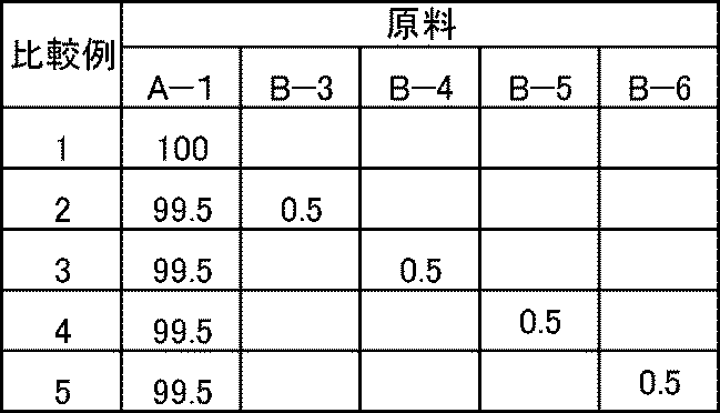
- Example 2 to 8 and Comparative Examples 1 to 5 were carried out under the same conditions as in Example 1 except that the ethylene copolymer and filler in Example 1 were changed to the raw materials and blending amounts in Tables 1 and 2.
- a solar cell sealing material and a solar cell module were obtained.
- the compounding quantity described in Table 1 and Table 2 is a weight part.
- the obtained solar cell encapsulant was used as a sample by crosslinking the encapsulant by heating and pressing under the same conditions (145 ° C., 17 minutes) using the vacuum laminator. About the obtained sample, the external appearance was evaluated by measuring a total light transmittance and HAZE using a haze meter (made by BYK Gardner).
- the adhesion was evaluated by measuring the peel strength.
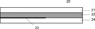
- a method for producing a measurement sample will be described with reference to FIG.
- the solar cell sealing material 22 was prepared using the obtained solar cell sealing material.
- a laminated sheet 20 is formed by sequentially laminating a glass plate 21 having a thickness of 3 mm, a solar cell sealing material 22, a peelable sheet 23 having a peel-treated surface facing down, and a polyethylene terephthalate film 24 having a thickness of 100 ⁇ m. did.
- the vacuum laminator the laminate 20 was heated and pressurized under the same conditions (145 ° C., 17 minutes) to crosslink the sealing material.
- the peelable sheet is half the total length of the laminate 20, and the polyethylene terephthalate film 24 is not in close contact with the solar cell encapsulant 22 for 60% of the total length of the laminate 20.
- the laminate 20 was cut into a strip shape having a width of 1 cm to obtain a sample.
- the sample was allowed to stand for 24 hours in an environment of a temperature of 23 ° C. and a humidity of 50% RH, and then the peel strength was measured under the conditions of a peel rate of 100 mm / min and a peel angle of 180 °.
- the upper side is the upper surface and the lower side is the lower surface.
- the peel strength was measured according to JIS K 6854-2.
- Isc short-circuit current
- Voc open circuit voltage
- Pm maximum output
- the PID test was conducted by the following method to evaluate the PID resistance.
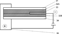
- the solar cell module shown in FIG. 3 was produced. Specifically, the light-receiving surface side protective glass 31 having a thickness of 3 mm, the solar cell sealing material 32A, the power generation element 33, the solar cell sealing material 32B, and the back surface protection member 34 are stacked in this order, and the vacuum laminator is used. A solar cell module was obtained by thermocompression bonding under the same conditions, and was further fixed to the metal frame 35. Next, as shown in FIG. 3, a sample was prepared by wiring the positive output terminal and the negative output terminal as a negative pole for the power generation element and the metal frame 35 as a positive pole.
- the IV characteristics (Isc and Pm) and the leakage current were measured as initial values for the sample before the test, and it was confirmed that the initial leakage current was 0 A in all the examples and comparative examples.
- the IV characteristics were measured using a solar cell solar simulator MS-180AAA (USHIO SPEX) and a solar cell characteristic tester DKPVT-30 (DENKEN).
- the leakage current was measured by measuring the value of current flowing from the frame through the sealing material to the power generation element by applying a voltage of 1000 V by setting the output terminal with the power generation element as the negative pole and the frame as the positive pole.
- the sample was subjected to a PID test under the following conditions, and the IV characteristics and leakage current after the test were measured.
- Pm retention rate (initial Pm value / Pm value after test) ⁇ 100 -PID resistance test conditions A temperature of 60 ° C. and a humidity of 85% RH, and an applied voltage of 1000 V for 96 hours.
- the measurement was performed after covering the light receiving surface side protective glass with water and further increasing the potential difference between the power generation element and the light receiving surface side protective glass.
- the total light transmittance was 87% or more and the HAZE value was 5.21% or less, and the transparency was excellent. That is, it was found that good results were obtained in which the total light transmittance exceeded 85% and the HAZE value was less than 5.5%.
- the total light transmittance is 87% or more, but the HAZE value is 5 in Comparative Examples 2, 3, and 5. The result was 5% or more.
- the peel strength was 113.2 N or more, and a peel strength exceeding 110 N was obtained.
- the peel strength was 110 N or less in all cases except for Comparative Example 1 in which the additive having ion trapping ability was not added.
- the conversion efficiency retention after 2000 hours was 99.8% or more, and a result exceeding 99% was obtained.
- the conversion efficiency retention after 2000 hours is all maintained at the 90% level, but is generally lower than the present example. It was.
- Table 4 shows that this example has excellent PID resistance.
- the Pm retention after the PID test was 99.0% or more, and a Pm retention exceeding 95% was obtained.
- the Pm retention rate was lower than 90% (for example, the comparative example 2 had a Pm retention rate of 65.6% and the comparative example 5 had a Pm retention rate of 8.4%).
- the leakage current after the PID test was 0.26 ⁇ A or less, and a result of less than 0.3 ⁇ A was obtained.
- the leakage current after the PID test was 2,67 ⁇ A even in the lowest comparative example 4, and it was found that there was a leakage current higher by one digit or more.
- Comparative Example 1 in which an additive having ion trapping ability is not added, as shown in Table 3, although transparency and peel strength are excellent, there is a problem in evaluation after the PID test.
- the inorganic ion scavengers of Comparative Examples 2 to 5 not included in the present invention inorganic ion scavengers having anion scavenging ability
- the HAZE value is lowered and the adhesion is also lowered. I understood it.
- results inferior to those of the examples of the present application were obtained.
Landscapes
- Chemical & Material Sciences (AREA)
- Organic Chemistry (AREA)
- Health & Medical Sciences (AREA)
- Chemical Kinetics & Catalysis (AREA)
- Medicinal Chemistry (AREA)
- Polymers & Plastics (AREA)
- Engineering & Computer Science (AREA)
- Materials Engineering (AREA)
- Photovoltaic Devices (AREA)
- Compositions Of Macromolecular Compounds (AREA)
- Sealing Material Composition (AREA)
Abstract
本発明は、透明性が良好で、長期の使用でも受光面側保護ガラスとの密着性の低下を抑制し、耐PID性が良好な太陽電池封止材を成形できる太陽電池封止材用樹脂組成物の提供を目的とする。 本発明の太陽電池封止材用樹脂組成物は、エチレン共重合体および無機イオン捕集剤を含み、前記無機イオン捕集剤が、五価金属の酸化物、六価金属の酸化物、七価金属の酸化物、リン酸金属塩からなる群より選択する1種以上を含み、前記エチレン共重合体100重量部に対して、前記無機イオン捕集剤を0.01~0.5重量部含むものである。
Description
本発明は、太陽電池封止材の製造に使用する太陽電池封止材用樹脂組成物および太陽電池封止材用マスターバッチに関する。また、太陽電池封止材および太陽電池モジュールに関する。
エコロジーの観点から太陽光発電システム(以下、太陽電池ともいう)は、クリーンなエネルギー源として幅広く使用されており、太陽電池のさらなる高効率化、長寿命化などを目指した技術開発が推進されている。
太陽電池は、複数の太陽電池モジュールを組み合わせたものであるが、太陽電池モジュールに組み込む発電素子は、シリコン等の半導体を用いて太陽光エネルギーを直接電気エネルギーに変換することで発電している。しかし、前記半導体は直接外気と接触すると発電機能が低下するため、発電素子を太陽電池封止材(以下、封止材ともいう)で被覆することで保護している。前記封止材として、現在では架橋エチレン・酢酸ビニル樹脂(以下、EVAともいう)が低コスト、透明性および発電素子への接着性等の観点から使用されている。しかし、EVAは、高絶縁性を有していないため、発電時に発生する漏れ電流や各種イオンが前記半導体まで移動し、半導体に悪影響を及ぼすことが問題となっている。
また、近年ではメガソーラなどの大規模太陽光発電システムが各地に設置されているが、発電した電流の伝達損失を下げる目的で、システム電圧を600~1000V程度に上げて送電する高電圧化が進んでいる。前記高電圧化により、太陽電池モジュール内のフレームと半導体との電位差が大きくなる。また、受光面側保護ガラスは、封止材に比べて体積抵抗率が低いことから、発電素子と受光面側保護ガラスの間でもその電位差が大きくなり、半導体素子へと電流が伝わりやすい環境が構築される。加えて、高電圧化により、ガラスに含まれるNa成分がNa+イオンとして解離する。そして、前記Na+イオンがガラス内、ガラス/封止材および封止材/半導体素子へと移動し、経時的に発電素子表面にNa+イオンが集積し、半導体素子の電子の移動を妨げる劣化現象が起きる。また、移動の際に各界面で析出し、封止材等の保護部材表面が剥離してしまう劣化現象も起きる。上述の太陽電池モジュールの高電圧化により、太陽電池モジュール及び半導体素子が劣化し、変換効率を低下させる現象をPID(PotentIal Induced DegradatIon)現象という。
PID現象の改善を直接の目的とはしていないが、封止材の体積抵抗率を増やす検討がされている。特許文献1では、珪素原子に直接結合する官能基の炭素原子数が4以下のシランカップリング剤を配合した封止材が開示されている。また、特許文献2および3では、EVAに代えてエチレン-αオレフィン共重合体等のポリオレフィン樹脂を使用した封止材が開示されている。また、特許文献4では、カオリナイトを焼成したメタカオリンを配合した封止材が開示されている。
しかし、ポリオレフィン樹脂を用いると、体積抵抗率は高いが、製造時に配合される添加剤の作用により耐PID性が低くなり、メタカオリンを配合した封止材は、透明性が不足するという問題があった。このため、透明性に優れ、且つ耐PID性が良好で、更に密着性に優れる封止材が求められていた。
本発明は、上記背景に鑑みて成されたものであり、透明性が良好で、長期間使用した場合でも受光面側保護ガラスとの密着性の低下を抑制し、耐PID性が良好な太陽電池封止材を成形できる太陽電池封止材用樹脂組成物および太陽電池封止材用マスターバッチ、並びに太陽電池封止材の提供を目的とする。
本発明者等が鋭意研究を重ねた結果、以下の態様において上記課題を解決できることを見出し、本発明を完成させるに至った。
[1] エチレン共重合体および無機イオン捕集剤を含み、前記無機イオン捕集剤が、五価金属の酸化物、六価金属の酸化物、七価金属の酸化物、リン酸金属塩からなる群より選択する1種以上を含み、前記エチレン共重合体100重量部に対して、前記無機イオン捕集剤を0.01~0.5重量部を含む、太陽電池封止材用樹脂組成物。
[2] 前記無機イオン捕集剤の平均粒子径が0.01~100μmである、[1]に記載の太陽電池封止材用樹脂組成物。
[3] 前記五価金属がアンチモンである、[1]または[2]に記載の太陽電池封止材用樹脂組成物。
[4] 前記リン酸金属塩に用いる金属が、ジルコニウム、ビスマス、チタン、スズおよびタンタルから選択される少なくとも一種である[1]~[3]のいずれかに記載の太陽電池封止材用樹脂組成物。
[5] エチレン共重合体100重量部に対して、無機イオン捕集剤を0.01~0.5重量部を含む太陽電池封止材を成形するための太陽電池封止材用マスターバッチであって、エチレン共重合体および無機イオン捕集剤を含み、前記無機イオン捕集剤が、五価金属の酸化物、六価金属の酸化物、七価金属の酸化物、リン酸金属塩からなる群より選択する1種以上を含み、前記エチレン共重合体100重量部に対して、前記無機イオン捕集剤を0.01~20重量部を含む、太陽電池封止材用マスターバッチ。
[6] ペレット状に形成された、[5]に記載の太陽電池封止材用マスターバッチ。
[7] [1]~[4]に記載の太陽電池封止材用樹脂組成物または[5]または[6]に記載の太陽電池封止材用マスターバッチを含む混合物を成形してなる太陽電池封止材。
[8] 本発明の太陽電池モジュールは、[7]記載の太陽電池封止材を備える。
[1] エチレン共重合体および無機イオン捕集剤を含み、前記無機イオン捕集剤が、五価金属の酸化物、六価金属の酸化物、七価金属の酸化物、リン酸金属塩からなる群より選択する1種以上を含み、前記エチレン共重合体100重量部に対して、前記無機イオン捕集剤を0.01~0.5重量部を含む、太陽電池封止材用樹脂組成物。
[2] 前記無機イオン捕集剤の平均粒子径が0.01~100μmである、[1]に記載の太陽電池封止材用樹脂組成物。
[3] 前記五価金属がアンチモンである、[1]または[2]に記載の太陽電池封止材用樹脂組成物。
[4] 前記リン酸金属塩に用いる金属が、ジルコニウム、ビスマス、チタン、スズおよびタンタルから選択される少なくとも一種である[1]~[3]のいずれかに記載の太陽電池封止材用樹脂組成物。
[5] エチレン共重合体100重量部に対して、無機イオン捕集剤を0.01~0.5重量部を含む太陽電池封止材を成形するための太陽電池封止材用マスターバッチであって、エチレン共重合体および無機イオン捕集剤を含み、前記無機イオン捕集剤が、五価金属の酸化物、六価金属の酸化物、七価金属の酸化物、リン酸金属塩からなる群より選択する1種以上を含み、前記エチレン共重合体100重量部に対して、前記無機イオン捕集剤を0.01~20重量部を含む、太陽電池封止材用マスターバッチ。
[6] ペレット状に形成された、[5]に記載の太陽電池封止材用マスターバッチ。
[7] [1]~[4]に記載の太陽電池封止材用樹脂組成物または[5]または[6]に記載の太陽電池封止材用マスターバッチを含む混合物を成形してなる太陽電池封止材。
[8] 本発明の太陽電池モジュールは、[7]記載の太陽電池封止材を備える。
本発明に係る無機イオン捕集剤は、エチレン共重合体と分散性が良好であることから、本発明の太陽電池封止材は、透明性および密着性が良好である。また、太陽電池封止材は、無機イオン捕集剤の配合により陽イオンを捕捉し、陽イオンを固定化する作用が高いため、太陽電池封止材の絶縁性の向上と良好な耐PID性が得られた。
本発明により、透明性が良好で、長期間使用した場合でも受光面側保護ガラスとの密着性の低下を抑制し、耐PID性が良好な太陽電池封止材を成形できる太陽電池封止材用樹脂組成物および太陽電池封止材用マスターバッチを提供できた。
以下、本発明を詳細に説明する。なお、本明細書において、「任意の数A以上、任意の数B以下」及び「任意の数A~任意の数B」の記載は、数A及び数Aより大きい範囲であって、数B及び数Bより小さい範囲を意味する。
本発明の太陽電池封止材用樹脂組成物は、エチレン共重合体および無機イオン捕集剤を含む。太陽電池封止材用樹脂組成物(以下、樹脂組成物ともいう)は、シート状に成形して太陽電池封止材として使用することが好ましい。更に、発電素子を一対の太陽電池封止材により挟持し、封止(被覆)することで太陽電池モジュールを構成する太陽電池封止材として使用することが好ましい。
〔エチレン共重合体〕
本発明においてエチレン共重合体は、二種類以上の単量体の混合物を重合した共重合体である。前記エチレン共重合体は、重合に使用する単量体の少なくとも一種類がエチレン単量体であればよく、ジエンモノマー、プロピレン、α-オレフィン等を共重合させてもよい。具体的には、エチレン・酢酸ビニル共重合体(EVA)、エチレン・アクリル酸メチル共重合体、エチレン・アクリル酸エチル共重合体、エチレン・メタクリル酸メチル共重合体、エチレン・メタクリル酸エチル共重合体、エチレン・酢酸ビニル系多元共重合体、エチレン・アクリル酸メチル系多元共重合体、エチレン・アクリル酸エチル系多元共重合体、エチレン・メタクリル酸メチル系多元共重合体、エチレン・メタクリル酸エチル系多元共重合体、エチレン・プロピレン共重合体、エチレン・1-ブテン共重合体、エチレン・4-メチル-1-ペンテン共重合体、エチレン・1-ヘキセン共重合体、エチレン・1-オクテン共重合体、エチレン・プロピレン・ジシクペンタジエン共重合体、エチレン・プロピレン・5-エチリデン-2-ノルボルネン共重合体、エチレン・プロピレン・1,6-ヘキサジエン共重合体などが挙げられる。これらの中でも、透明性、ラミネート性の面からEVAが好ましく、酢酸ビニルを15~40重量%使用したEVAがより好ましく、酢酸ビニルを25~35重量%使用したEVAがより好ましい。
本発明においてエチレン共重合体は、二種類以上の単量体の混合物を重合した共重合体である。前記エチレン共重合体は、重合に使用する単量体の少なくとも一種類がエチレン単量体であればよく、ジエンモノマー、プロピレン、α-オレフィン等を共重合させてもよい。具体的には、エチレン・酢酸ビニル共重合体(EVA)、エチレン・アクリル酸メチル共重合体、エチレン・アクリル酸エチル共重合体、エチレン・メタクリル酸メチル共重合体、エチレン・メタクリル酸エチル共重合体、エチレン・酢酸ビニル系多元共重合体、エチレン・アクリル酸メチル系多元共重合体、エチレン・アクリル酸エチル系多元共重合体、エチレン・メタクリル酸メチル系多元共重合体、エチレン・メタクリル酸エチル系多元共重合体、エチレン・プロピレン共重合体、エチレン・1-ブテン共重合体、エチレン・4-メチル-1-ペンテン共重合体、エチレン・1-ヘキセン共重合体、エチレン・1-オクテン共重合体、エチレン・プロピレン・ジシクペンタジエン共重合体、エチレン・プロピレン・5-エチリデン-2-ノルボルネン共重合体、エチレン・プロピレン・1,6-ヘキサジエン共重合体などが挙げられる。これらの中でも、透明性、ラミネート性の面からEVAが好ましく、酢酸ビニルを15~40重量%使用したEVAがより好ましく、酢酸ビニルを25~35重量%使用したEVAがより好ましい。
前記エチレン共重合体は、成形性、機械的強度などを考慮すると、メルトフローレート(JIS K7210準拠)が0.1~60g/10minであることが好ましく、0.5~45g/10minがより好ましい。なおメルトフローレートはMFRともいう。
〔無機イオン捕集剤〕
本発明において無機イオン捕集剤を配合した封止材は、体積抵抗率が増加したことで絶縁性が向上する。更に前記無機イオン捕集剤は、絶縁性および耐PID性を低下させる導電性物質(イオンおよびラジカル等)を捕捉できることから、良好な耐PID性が得られる。前記導電性物質は、エチレン共重合中の加水分解物イオン(H+)、ガラスの電気分解により発生するNa+イオンや安定剤由来の金属イオン(例えばCa2+、Zn2+、Mg2+)等の陽イオンが挙げられる。無機イオン捕集剤は、例えば、前記金属イオンを捕捉するとイオン交換反応により、直ちに難水溶性のリン酸金属塩や金属含有のオキソアニオン塩を生成するため、高い体積抵抗率および良好な耐PID性を有する封止材が得られる。
本発明において無機イオン捕集剤を配合した封止材は、体積抵抗率が増加したことで絶縁性が向上する。更に前記無機イオン捕集剤は、絶縁性および耐PID性を低下させる導電性物質(イオンおよびラジカル等)を捕捉できることから、良好な耐PID性が得られる。前記導電性物質は、エチレン共重合中の加水分解物イオン(H+)、ガラスの電気分解により発生するNa+イオンや安定剤由来の金属イオン(例えばCa2+、Zn2+、Mg2+)等の陽イオンが挙げられる。無機イオン捕集剤は、例えば、前記金属イオンを捕捉するとイオン交換反応により、直ちに難水溶性のリン酸金属塩や金属含有のオキソアニオン塩を生成するため、高い体積抵抗率および良好な耐PID性を有する封止材が得られる。
前記無機イオン捕集剤は、水の存在下で陽イオン交換特性を示す不溶性無機化合物が好ましい。具体的には、五価金属の酸化物、六価金属の酸化物、七価金属の酸化物、リン酸金属塩からなる群より選択する1種以上の化合物である。なお五価金属の酸化物、六価金属の酸化物および七価金属の酸化物は、含水酸化物も含む。
前記五価金属の酸化物は、例えば五酸化バナジウム、含水五酸化バナジウム、バナジン酸チタン、バナジン酸アルミニウム、バナジン酸ジルコニウム、リンバナジン酸、バナジンモリブデン酸、フェロシアン化バナジウム、五酸化ニオブ、含水五酸化ニオブ、五酸化タンタル、含水五酸化タンタル、五酸化アンチモン、含水酸化アンチモン(V)が挙げられる。
前記六価金属の酸化物は、例えばアンチモンタングステン酸、アンチモン酸チタン、アンチモン酸ジルコニウム、アンチモン酸スズ、アンチモン酸鉄、アンチモン酸アルミニウム、アンチモン酸クロム、アンチモン酸タンタル、アンチモン酸マンガン、アンチモン酸ビスマス、リンアンチモン酸、アンチモンモリブデン酸が挙げられる。
前記七価金属の酸化物は、例えばアルカリ金属イオン又はアルカリ土類金属イオンを酸処理により溶出させて得られる過マンガン酸カリウム、過マンガン酸カルシウム、過マンガン酸アルミニウム等が挙げられる。
また、前記無機イオン捕集剤は、五価金属の酸化物、六価金属の酸化物または七価金属の酸化物を含有する鉱物も好ましい。具体例としては、自然アンチモン鉱およびバレンチン鉱等を砕いて、粉末化した形態が挙げられる。
前記リン酸金属塩は、例えばリン酸ジルコニウム、リン酸ビスマス、リン酸チタン、リン酸スズ、リン酸タンタル等が挙げられる。リン酸金属塩の金属としては、ジルコニウム、ビスマス、チタン、スズおよびタンタルから選択される少なくとも一種であることが好ましい。
無機イオン捕集剤は、1種単独または2種以上を併用して用いることができる。
前記五価金属の酸化物は、例えば五酸化バナジウム、含水五酸化バナジウム、バナジン酸チタン、バナジン酸アルミニウム、バナジン酸ジルコニウム、リンバナジン酸、バナジンモリブデン酸、フェロシアン化バナジウム、五酸化ニオブ、含水五酸化ニオブ、五酸化タンタル、含水五酸化タンタル、五酸化アンチモン、含水酸化アンチモン(V)が挙げられる。
前記六価金属の酸化物は、例えばアンチモンタングステン酸、アンチモン酸チタン、アンチモン酸ジルコニウム、アンチモン酸スズ、アンチモン酸鉄、アンチモン酸アルミニウム、アンチモン酸クロム、アンチモン酸タンタル、アンチモン酸マンガン、アンチモン酸ビスマス、リンアンチモン酸、アンチモンモリブデン酸が挙げられる。
前記七価金属の酸化物は、例えばアルカリ金属イオン又はアルカリ土類金属イオンを酸処理により溶出させて得られる過マンガン酸カリウム、過マンガン酸カルシウム、過マンガン酸アルミニウム等が挙げられる。
また、前記無機イオン捕集剤は、五価金属の酸化物、六価金属の酸化物または七価金属の酸化物を含有する鉱物も好ましい。具体例としては、自然アンチモン鉱およびバレンチン鉱等を砕いて、粉末化した形態が挙げられる。
前記リン酸金属塩は、例えばリン酸ジルコニウム、リン酸ビスマス、リン酸チタン、リン酸スズ、リン酸タンタル等が挙げられる。リン酸金属塩の金属としては、ジルコニウム、ビスマス、チタン、スズおよびタンタルから選択される少なくとも一種であることが好ましい。
無機イオン捕集剤は、1種単独または2種以上を併用して用いることができる。
前記無機イオン捕集剤は、主として陰イオンを交換する化合物を含まない。陰イオンを交換する無機イオン捕集剤としては、例えば、ハイドロタルサイト、鉛ヒドロキシアパタイト、カドミウムヒドロキシアパタイト、ハイドロタルサイト、三酸化ビスマス、五酸化ビスマス、含水酸化ビスマス(III)、含水酸化ビスマス(V)及び含水酸化硝酸ビスマス(III)等が挙げられる。しかし、本発明の課題を解決できる範囲内であれば、前記化合物を併用することを妨げない。
前記無機イオン捕集剤の平均粒子径は、0.1~100μmが好ましく、0.1~50μmがより好ましく、0.1~30μmが更に好ましい。0.1~100μmの範囲であることで導電性物質の捕捉効率および密着性がより高い封止材が得られる。なお平均粒子径は、電子顕微鏡の拡大写真(千倍~1万倍程度)から10~20個程度の粒子径を平均した数値である。
前記無機イオン捕集剤は、エチレン共重合体100重量部に対して0.01~5重量部を配合することが好ましく、0.01~1重量部がより好ましく、0.1~0.5重量部が更に好ましい。0.01~5重量部で配合することで透明性と耐PID性を高い水準で両立し易くなり、密着性がより低下し難くなる。また、配合量を1重量部以下とすることにより透明性がより改善し、更に、配合量を0.5重量部以下とすることにより特に優れた透明性を実現できる。また、樹脂組成物は、無機イオン捕集剤を高濃度に配合した太陽電池封止材用マスターバッチであってもよい。かかる場合、エチレン共重合体100重量部に対して無機イオン捕集剤を1~20重量部配合することが好ましく、1~10重量部がより好ましい。樹脂組成物をマスターバッチとして製造し、それを用いて封止材を製造すると無機イオン捕集剤を封止材中により均一に分散できる。最終的に、封止材中の無機イオン捕集剤は、エチレン共重合体100重量部に対して0.01~1重量部程度であることが好ましい。
また、前記無機イオン捕集剤のBET比表面積は、5~200m2/gが好ましく、10~100m2/gがより好ましい。5~200m2/gの範囲にあることで導電性物質を更に捕捉できるため、透明性がより向上し、密着性がより低下し難くなる。
〔太陽電池封止材用樹脂組成物〕
本発明の太陽電池封止材用樹脂組成物は、エチレン共重合体および無機イオン捕集剤に加えて、任意成分として架橋剤、架橋助剤、シランカップリング剤、紫外線吸収剤、光安定剤、酸化防止剤、光拡散剤、波長変換剤、着色剤、分散剤、および難燃剤等の添加剤を配合することができる。また、前記任意成分は、封止材を製造する際に別途配合することもできる。
本発明の太陽電池封止材用樹脂組成物は、エチレン共重合体および無機イオン捕集剤に加えて、任意成分として架橋剤、架橋助剤、シランカップリング剤、紫外線吸収剤、光安定剤、酸化防止剤、光拡散剤、波長変換剤、着色剤、分散剤、および難燃剤等の添加剤を配合することができる。また、前記任意成分は、封止材を製造する際に別途配合することもできる。
前記架橋剤は、エチレン酢酸ビニル共重合体の高温使用下における熱変形を防止するために使用する。架橋剤は有機過酸化物が好ましい。具体的には、例えばtert-ブチルパーオキシイソプロピルカーボネート、tert-ブチルパーオキシ-2-エチルヘキシルイソプロピルカーボネート、tert-ブチルパーオキシアセテート、tert-ブチルクミルパーオキサイド、2,5-ジメチル-2,5-ジ(tert-ブチルパーオキシ)ヘキサン、ジ-tert-ブチルパーオキサイド、2,5-ジメチル-2,5-ジ(tert-ブチルパーオキシ)ヘキシン-3、2,5-ジメチル-2,5-ジ(tert-ブチルパーオキシ)ヘキサン、1,1-ジ(tert-ヘキシルパーオキシ)-3,3,5-トリメチルシクロヘキサン、1,1-ジ(tert-ブチルパーオキシ)シクロヘキサン、1,1-ジ(tert-ヘキシルパーオキシ)シクロヘキサン、1,1-ジ(tert-アミルパーオキシ)シクロヘキサン、2,2-ジ(tert-ブチルパーオキシ)ブタン、メチルエチルケトンパーオキサイド、2,5-ジメチルヘキシル-2,5-ジパーオキシベンゾエート、tert-ブチルハイドロパーオキサイド、p-メンタンハイドロパーオキサイド、ジベンゾイルパーオキサイド、p-クロルベンゾイルパーオキサイド、tert-ブチルパーオキシイソブチレート、n-ブチル-4,4-ジ(tert-ブチルパーオキシ)バレレート、エチル-3,3-ジ(tert-ブチルパーオキシ)ブチレート、ヒドロキシヘプチルパーオキサイド、ジクロヘキサノンパーオキサイド、1,1-ジ(tert-ブチルパーオキシ)3,3,5-トリメチルシクロヘキサン、n-ブチル-4,4-ジ(tert-ブチルパーオキシ)バレレート、および2,2-ジ(tert-ブチルパーオキシ)ブタン等が挙げられる。
架橋剤は、エチレン共重合体100重量部に対して、0.05~3重量部配合するのが好ましい。
架橋剤は、エチレン共重合体100重量部に対して、0.05~3重量部配合するのが好ましい。
前記架橋助剤は、架橋剤の架橋反応の効率的に進行させるために使用する。架橋助剤は、ポリアリル化合物やポリアクリロキシ化合物のような不飽和化合物が好ましい。具体的には、例えばトリアリルイソシアヌレート、トリアリルシアヌレート、ジアリルフタレート、ジアリルフマレート、ジアリルマレエート、エチレングリコールジアクリレート、エチレングリコールジメタクリレート、およびトリメチロールプロパントリメタクリレート等が挙げられる。
架橋助剤は、エチレン共重合体100重量部に対して、0.05~3重量部配合するのが好ましい。
架橋助剤は、エチレン共重合体100重量部に対して、0.05~3重量部配合するのが好ましい。
前記シランカップリング剤は、受光面側保護ガラスや発電素子等に対する密着性を向上させるために使用する。シランカップリング剤は、ビニル基、アクリロキシ基およびメタクリロキシ基等の官能基、ならびにアルコキシ基のような加水分解性官能基を有する化合物である。具体的には、例えばビニルトリクロルシラン、ビニルトリス(βメトキシエトキシ)シラン、ビニルトリエトキシシラン、ビニルトリメトキシシラン、γ-メタクリロキシプロピルトリメトキシシラン、β-(3,4-エポキシシクロヘキシル)エチルトリメトキシシラン、γ-グリシドキシプロピルメチルジエトキシシラン、N-β(アミノエチル)γ-アミノプロピルトリメトキシシラン、N-β(アミノエチル)γ-アミノプロピルメチルジメトキシシラン、γ-アミノプロピルトリエトキシシラン、N-フェニル-γ-アミノプロピルトリメトキシシラン、γ-メルカプトプロピルトリメトキシシラン、およびγ-クロロプロピルトリメトキシシランなどが挙げられる。
シランカップリング剤は、エチレン共重合体と無機イオン捕集剤の合計100重量部に対して、0.05~3重量部配合するのが好ましい。
シランカップリング剤は、エチレン共重合体と無機イオン捕集剤の合計100重量部に対して、0.05~3重量部配合するのが好ましい。
前記紫外線吸収剤は、耐候性を向上さるために使用する。紫外線吸収剤は、ベンゾフェノン系化合物、ベンゾトリアゾール系化合物、トリアジン系化合物、サリチル酸エステル系化合物等が好ましい。具体例としては、2-ヒドロキシ-4-メトキシベンゾフェノン、2-ヒドロキシ-4-メトキシ-2’-カルボキシベンゾフェノン、2-ヒドロキシ-4-オクトキシベンゾフェノン、2-ヒドロキシ-4-n-ドデシルオキシベンゾフェノン、2-ヒドロキシ-4-n-オクタデシルオキシベンゾフェノン、2-ヒドロキシ-4-ベンジルオキシベンゾフェノン、2-ヒドロキシ-4-メトキシ-5-スルホベンゾフェノン、2-ヒドロキシ-5-クロロベンゾフェノン、2,4-ジヒドロキシベンゾフェノン、2,2’-ジヒドロキシ-4-メトキシベンゾフェノン、2,2’-ジヒドロキシ-4,4’-ジメトキシベンゾフェノン、2,2’,4,4’-テトラヒドロキシベンゾフェノン、2-(2-ヒドロキシ-5-メチルフェニル)ベンゾトリアゾール、2-(2-ヒドロキシ-5-t-ブチルフェニル)ベンゾトリアゾール、2-(2-ヒドロキシ-3,5-ジメチルフェニル)ベンゾトリアゾール、2-(2-メチル-4-ヒドロキシフェニル)ベンゾトリアゾール、2-(2-ヒドロキシ-3-メチル-5-t-ブチルフェニル)ベンゾトリアゾール、2-(2-ヒドロキシ-3,5-ジ-t-ブチルフェニル)ベンゾトリアゾール、2-(2-ヒドロキシ-3,5-ジメチルフェニル)-5-メトキシベンゾトリアゾール、2-(2-ヒドロキシ-3-t-ブチル-5-メチルフェニル)-5-クロロベンゾトリアゾール、2-(2-ヒドロキシ-5-t-ブチルフェニル)-5-クロロベンゾトリアゾール、2-[4,6-ビス(2,4-ジメチルフェニル)-1,3,5-トリアジン-2-イル]-5-(オクチルオキシ)フェノール、2-(4,6-ジフェニル-1,3,5-トリアジン-2-イル)-5-(ヘキシルオキシ)フェノール、フェニルサリチレート、およびp-オクチルフェニルサリチレート等が挙げられる。
紫外線吸収剤は、エチレン共重合体100重量に対して、0.01~3重量部配合するのが好ましい。
紫外線吸収剤は、エチレン共重合体100重量に対して、0.01~3重量部配合するのが好ましい。
前記光安定剤は、耐候性を向上さるために使用し、紫外線吸収剤と併用すると耐候性が更に向上する。光安定剤は、ヒンダードアミン系化合物が好ましい。具体例としては、コハク酸ジメチル-1-(2-ヒドロキシエチル)-4-ヒドロキシ-2,2,6,6-テトラメチルピペリジン重縮合物、ポリ[{6-(1,1,3,3-テトラメチルブチル)アミノ-1,3,5-トリアジン-2,4-ジイル}{(2,2,6,6-テトラメチル-4-ピペリジル)イミノ}ヘキサメチレン{(2,2,6,6-テトラメチル-4-ピペリジル)イミノ}]、N,N’-ビス(3-アミノプロピル)エチレンジアミン-2,4-ビス[N-ブチル-N-(1,2,2,6,6-ペンタメチル-4-ピペリジル)アミノ]-6-クロロ-1,3,5-トリアジン縮合物、ビス(2,2,6,6-テトラメチル-4-ピペリジル)セパレート、および2-(3,5-ジ-tert-4-ヒドロキシベンジル)-2-n-ブチルマロン酸ビス(1,2,2,6,6-ペンタメチル-4-ピペリジル)などが挙げられる。
光安定剤は、エチレン共重合体100重量部に対して、0.01~3重量部配合するのが好ましい。
光安定剤は、エチレン共重合体100重量部に対して、0.01~3重量部配合するのが好ましい。
前記酸化防止剤は、高温下での安定性を向上させるために使用する。酸化防止剤は、モノフェノール系化合物、ビスフェノール系化合物、高分子型フェノール系化合物、硫黄系化合物、燐酸系化合物等が好ましい。具体例としては、2,6-ジ-tert-ブチル-p-クレゾール、ブチル化ヒドロキシアニゾール、2,6-ジ-tert-ブチル-4-エチルフェノール、2,2’-メチレン-ビス-(4-メチル-6-tert-ブチルフェノール)、2,2’-メチレン-ビス-(4-エチル-6-tert-ブチルフェノール)、4,4’-チオビス-(3-メチル-6-tert-ブチルフェノール)、4,4’-ブチリデン-ビス-(3-メチル-6-tert-ブチルフェノール)、3,9-ビス〔{1,1-ジメチル-2-{β-(3-tert-ブチル-4-ヒドロキシ-5-メチルフェニル)プロピオニルオキシ}エチル}2,4,8,10-テトラオキサスピロ〕5,5-ウンデカン、1,1,3-トリス-(2-メチル-4-ヒドロキシ-5-tert-ブチルフェニル)ブタン、1,3,5-トリメチル-2,4,6-トリス(3,5-ジ-tert-ブチル-4-ヒドロキシベンジル)ベンゼン、テトラキス-{メチレン-3-(3’,5’-ジ-tert-ブチル-4’-ヒドロキシフェニル)プロピオネート}メタン、ビス{(3,3’-ビス-4’-ヒドロキシ-3’-tert-ブチルフェニル)ブチリックアシッド}グルコールエステル、ジラウリルチオジプロピオネート、ジミリスチルチオジプロピオネート、ジステアリルチオプロピオネート、トリフェニルホスファイト、ジフェニルイソデシルホスファイト、フェニルジイソデシルホスファイト、4,4’-ブチリデン-ビス-(3-メチル-6-tert-ブチルフェニル-ジ-トリデシル)ホスファイト、サイクリックネオペンタンテトライルビス(オクタデシルホスファイト)、トリスジフェニルホスファイト、ジイソデシルペンタエリスリトールジホスファイト、9,10-ジヒドロ-9-オキサ-10-ホスファフェナントレン-10-オキサイド、10-(3,5-ジ-tert-ブチル-4-ヒドロキシベンジル)-9,10-ジヒドロ-9-オキサ-10-ホスファフェナントレン-10-オキサイド、10-デシロキシ-9,10-ジヒドロ-9-オキサ-10-ホスファフェナントレン、サイクリックネオペンタンテトライルビス(2,4-ジ-tert-ブチルフェニル)ホスファイト、サイクリックネオペンタンテトライルビス(2,6-ジ-tert-メチルフェニル)ホスファイト、および2,2-メチレンビス(4,6-tert-ブチルフェニル)オクチルホスファイト等が挙げられる。
酸化防止剤は、エチレン共重合体100重量部に対して、0.05~3重量部配合するのが好ましい。
酸化防止剤は、エチレン共重合体100重量部に対して、0.05~3重量部配合するのが好ましい。
本発明の太陽電池封止材用樹脂組成物は、エチレン共重合体と無機イオン捕集剤とを一般的な高速せん断型混合機であるヘンシェルミキサーまたはスーパーミキサー等に投入し混合した後、二本ロール、三本ロール、加圧ニーダー、バンバリーミキサー、単軸混練押出し機または二軸混練押出し機等を用いて溶融混練を行い、ペレット状に押出し成形して得ることができる。また、前記溶融混錬後にシート状に加工した後、ペレット状に成形することもできる。
本発明の太陽電池封止材は、前記太陽電池封止材用樹脂組成物または太陽電池封止材用マスターバッチをT-ダイ押出機、カレンダー成形機等の一般的な成形機を使用してシート状に成形することで製造できる。前記成形の際に、架橋剤、架橋助剤、シランカップリング剤、紫外線吸収剤、光安定剤および酸化防止剤を配合して成形することもできる。
前記封止材の厚みは、0.1~2mm程度が好ましい。
前記封止材の厚みは、0.1~2mm程度が好ましい。
本発明の太陽電池モジュールの構成の一例を、図1を用いて説明する。図1の太陽電池モジュールは、太陽側から受光面側保護ガラス11、太陽電池封止材12A、発電素子13、太陽電池封止材12B、裏面保護部材14の順に重ね、加熱・圧着することで製造できる。少なくとも太陽電池封止材12Aに本発明の太陽電池封止材を使用する。裏面保護部材14は、ガラス、またはアルミニウムをフッ化ビニルフィルムで挟んだ構成のシートまたはアルミニウムを耐加水分解性ポリエチレンテレフタレートフィルムで挟んだ構成のシート等が好ましい。また、加熱・加圧は、一般的には、真空ラミネーターを使用できる。なお本発明の太陽電池モジュールが図1の構成に限定されないことはいうまでも無い。
前記発電素子は、単結晶シリコン、多結晶シリコン、アモルファスシリコンなどのシリコン系、ガリウム-砒素、銅-インジウム-セレン、カドミウム-テルルなどのI-V族やII-VI族化合物半導体系、有機薄膜半導体系等の各種太陽電池素子を用いることができる。
次に本発明の実施例を示して更に詳細を説明するが、本発明はこれらによって限定されるものではない。例中、「部」とは「重量部」、「%」とは「重量%」をそれぞれ意味するものとする。
実施例で使用した原料は、以下のとおりである。
<エチレン共重合体>
(A-1)EVA(酢酸ビニル含有量:28重量%、MFR:20g/10min)
(A-2)EVA(酢酸ビニル含有量:33重量%、MFR:14g/10min)
<フィラー>
(B-1)無機イオン捕集剤(無機陽イオン交換剤、IXE-100(リン酸ジルコニウム塩)、東亞合成社製、平均粒子径:1.0μm)
(B-2)無機イオン捕集剤(無機陽イオン交換剤、IXE-300(酸化アンチモンとアンチモン酸金属塩の混合物)、東亞合成社製、平均粒子径:0.5μm)
(B-3)含水カオリン(はくとう土、ASP-200、東新化成社製、平均粒子径:0.4μm)
(B-4)ハイドロタルサイト(NAOX-91N、戸田工業社製、平均粒子径:0.15μm)
(B-5)イオン交換剤(無機陰イオン交換剤、IXE-700F、東亞合成社製、平均粒子径:1.5μm)
(B-6)三酸化ビスマス(202827、シグマアルドリッチジャパン社製、平均粒子径:7.0μm)
(A-1)EVA(酢酸ビニル含有量:28重量%、MFR:20g/10min)
(A-2)EVA(酢酸ビニル含有量:33重量%、MFR:14g/10min)
<フィラー>
(B-1)無機イオン捕集剤(無機陽イオン交換剤、IXE-100(リン酸ジルコニウム塩)、東亞合成社製、平均粒子径:1.0μm)
(B-2)無機イオン捕集剤(無機陽イオン交換剤、IXE-300(酸化アンチモンとアンチモン酸金属塩の混合物)、東亞合成社製、平均粒子径:0.5μm)
(B-3)含水カオリン(はくとう土、ASP-200、東新化成社製、平均粒子径:0.4μm)
(B-4)ハイドロタルサイト(NAOX-91N、戸田工業社製、平均粒子径:0.15μm)
(B-5)イオン交換剤(無機陰イオン交換剤、IXE-700F、東亞合成社製、平均粒子径:1.5μm)
(B-6)三酸化ビスマス(202827、シグマアルドリッチジャパン社製、平均粒子径:7.0μm)
(実施例1)
〔太陽電池封止材用マスターバッチの製造〕
(A-1)EVA 95部および(B-1)無機イオン捕集剤 5部をスーパーミキサー(カワタ社製)に投入し、温度25℃、時間3分間の条件で撹拌して混合物を得た。次いで前記混合物を二軸押出し機(日本プラコン社製)に投入し、押し出し、ペレタイザーでカットすることで太陽電池封止材用マスターバッチを得た。
別途、(A-1)EVA 91.25部、光安定剤8.75部を使用して、上記同様の方法で安定化剤マスターバッチを得た。
また別途、(A-1)EVA 85部、架橋剤5部、架橋助剤5部、シランカップリング剤を使用して、上記同様の方法で架橋剤マスターバッチを得た。
〔太陽電池封止材用マスターバッチの製造〕
(A-1)EVA 95部および(B-1)無機イオン捕集剤 5部をスーパーミキサー(カワタ社製)に投入し、温度25℃、時間3分間の条件で撹拌して混合物を得た。次いで前記混合物を二軸押出し機(日本プラコン社製)に投入し、押し出し、ペレタイザーでカットすることで太陽電池封止材用マスターバッチを得た。
別途、(A-1)EVA 91.25部、光安定剤8.75部を使用して、上記同様の方法で安定化剤マスターバッチを得た。
また別途、(A-1)EVA 85部、架橋剤5部、架橋助剤5部、シランカップリング剤を使用して、上記同様の方法で架橋剤マスターバッチを得た。
〔太陽電池封止材の製造〕
得られた太陽電池封止材用マスターバッチ、安定化剤マスターバッチ、架橋剤マスターバッチ、および希釈用の(A-1)EVAを用いて、(A-1)EVAが99.9部、(B-1)無機イオン捕集剤が0.1部の比率となるように調製して混合物を得た。次いで前記混合物をT-ダイ押出機に投入し、温度110℃でシート状に押出し成形することで厚さ0.5mmの太陽電池封止材を作製した。なお、太陽電池封止材が含む原料は下記の通りであり、前記原料の配合量は、EVA 100重量部に対して、以下の量になるように配合している。
・原料
架橋剤:2,5-ジメチル-2,5-ジ(tert-ブチルパーオキシ)ヘキサン 0.6部
架橋助剤:トリアリルイソシアヌレート 0.6部
シランカップリング剤:γ-メタクリロキシプロピルトリメトキシシラン 0.6部
光安定剤:N,N’-ビス(3-アミノプロピル)エチレンジアミン-2,4-ビス[N-ブチル-N-(1,2,2,6,6-ペンタメチル-4-ピペリジル)アミノ]-6-クロロ-1,3,5-トリアジン縮合物 0.4部
得られた太陽電池封止材用マスターバッチ、安定化剤マスターバッチ、架橋剤マスターバッチ、および希釈用の(A-1)EVAを用いて、(A-1)EVAが99.9部、(B-1)無機イオン捕集剤が0.1部の比率となるように調製して混合物を得た。次いで前記混合物をT-ダイ押出機に投入し、温度110℃でシート状に押出し成形することで厚さ0.5mmの太陽電池封止材を作製した。なお、太陽電池封止材が含む原料は下記の通りであり、前記原料の配合量は、EVA 100重量部に対して、以下の量になるように配合している。
・原料
架橋剤:2,5-ジメチル-2,5-ジ(tert-ブチルパーオキシ)ヘキサン 0.6部
架橋助剤:トリアリルイソシアヌレート 0.6部
シランカップリング剤:γ-メタクリロキシプロピルトリメトキシシラン 0.6部
光安定剤:N,N’-ビス(3-アミノプロピル)エチレンジアミン-2,4-ビス[N-ブチル-N-(1,2,2,6,6-ペンタメチル-4-ピペリジル)アミノ]-6-クロロ-1,3,5-トリアジン縮合物 0.4部
〔太陽電池モジュールの製造〕
得られた太陽電池封止材を使用して太陽電池封止材12Aおよび太陽電池封止材12Bを準備した。次いで、太陽電池封止材12A、発電素子13、太陽電池封止材12Bの順に重ね、更に図1に示すように厚さ3mmの受光面側保護ガラス11および裏面保護部材14を使用して積層した後、真空ラミネーターに投入し、真空下、145℃、17分間の条件で加熱及び加圧し、封止材を架橋させることで太陽電池モジュールを作製した。なお、真空ラミネーターは、LM-50×50-S(エヌ・ピー・シー社製)を使用した。
得られた太陽電池封止材を使用して太陽電池封止材12Aおよび太陽電池封止材12Bを準備した。次いで、太陽電池封止材12A、発電素子13、太陽電池封止材12Bの順に重ね、更に図1に示すように厚さ3mmの受光面側保護ガラス11および裏面保護部材14を使用して積層した後、真空ラミネーターに投入し、真空下、145℃、17分間の条件で加熱及び加圧し、封止材を架橋させることで太陽電池モジュールを作製した。なお、真空ラミネーターは、LM-50×50-S(エヌ・ピー・シー社製)を使用した。
(実施例2~8、比較例1~5)
実施例1のエチレン共重合体およびフィラーを表1および表2の原料と配合量に変更した以外は、実施例1と同様の条件で行うことにより実施例2~8および比較例1~5の太陽電池封止材、ならびに太陽電池モジュールを得た。なお、表1および表2に表記された配合量は、重量部である。
実施例1のエチレン共重合体およびフィラーを表1および表2の原料と配合量に変更した以外は、実施例1と同様の条件で行うことにより実施例2~8および比較例1~5の太陽電池封止材、ならびに太陽電池モジュールを得た。なお、表1および表2に表記された配合量は、重量部である。

〔外観評価〕
得られた太陽電池封止材を、前記真空ラミネーターを使用して、上記同様の条件(145℃、17分間)で加熱加圧することで封止材を架橋することで試料とした。得られた試料について、ヘーズメーター(BYK Gardner社製)を使用して全光線透過率およびHAZEを測定することで外観を評価した。
得られた太陽電池封止材を、前記真空ラミネーターを使用して、上記同様の条件(145℃、17分間)で加熱加圧することで封止材を架橋することで試料とした。得られた試料について、ヘーズメーター(BYK Gardner社製)を使用して全光線透過率およびHAZEを測定することで外観を評価した。
[剥離強度]
剥離強度を測定することで密着性を評価した。
まず測定試料の作製方法について図2を示して説明する。得られた太陽電池封止材を使用して太陽電池封止材22を準備した。図2に示すように厚さ3mmのガラス板21、太陽電池封止材22、剥離処理面を下面に向けた剥離性シート23、および厚さ100μmのポリエチレンテレフタレートフィルム24を順次重ね積層体20とした。前記真空ラミネーターを使用して積層体20を、上記同様の条件(145℃、17分間)で加熱加圧することで封止材を架橋した。なお、剥離性シートは積層体20の全長の半分の長さであり、積層体20の全長の60%部分について、ポリエチレンテレフタレートフィルム24は、太陽電池封止材22と密着していない。
次いで、積層体20を幅1cm幅の短冊状に切り取り試料とした。前記試料を温度23℃、湿度50%RH環境下に24時間静置した後、剥離速度100mm/min、剥離角180°の条件で剥離強度を測定した。なお、図2の上側を上面、下側を下面とする。また、剥離強度の測定はJIS K 6854-2に準拠した。
剥離強度を測定することで密着性を評価した。
まず測定試料の作製方法について図2を示して説明する。得られた太陽電池封止材を使用して太陽電池封止材22を準備した。図2に示すように厚さ3mmのガラス板21、太陽電池封止材22、剥離処理面を下面に向けた剥離性シート23、および厚さ100μmのポリエチレンテレフタレートフィルム24を順次重ね積層体20とした。前記真空ラミネーターを使用して積層体20を、上記同様の条件(145℃、17分間)で加熱加圧することで封止材を架橋した。なお、剥離性シートは積層体20の全長の半分の長さであり、積層体20の全長の60%部分について、ポリエチレンテレフタレートフィルム24は、太陽電池封止材22と密着していない。
次いで、積層体20を幅1cm幅の短冊状に切り取り試料とした。前記試料を温度23℃、湿度50%RH環境下に24時間静置した後、剥離速度100mm/min、剥離角180°の条件で剥離強度を測定した。なお、図2の上側を上面、下側を下面とする。また、剥離強度の測定はJIS K 6854-2に準拠した。
〔体積抵抗率〕
前記真空ラミネーターを使用して、得られた太陽電池封止材を上記同様の条件(145℃、17分間)で加熱加圧することで封止材を架橋することにより試料とした。前記試料についてデジタル超高抵抗/微少電流計 R8340(アドバンテスト社製)を使用して、体積抵抗率を測定した。
前記真空ラミネーターを使用して、得られた太陽電池封止材を上記同様の条件(145℃、17分間)で加熱加圧することで封止材を架橋することにより試料とした。前記試料についてデジタル超高抵抗/微少電流計 R8340(アドバンテスト社製)を使用して、体積抵抗率を測定した。
〔変換効率保持率〕
太陽電池モジュールについて、まずI-V特性を測定し、初期変換効率を算出した後、前記太陽電池モジュールを85℃85%RHに設定した恒温恒湿試験機に投入し1000時間静置し、前記の方法で変換効率を算出した。次いで、前記太陽電池モジュールを前記恒温恒湿試験機に投入し同条件でさら1000時間静置し、前記の方法で変換効率を算出した。なお、変換効率は、入光エネルギーとI-V特性測定から算出した最大出力(Pm)と、発電素子の面積から算出した。評価は初期変換効率を100とし、太陽電池モジュールの試験後の変換効率に対する初期変換効率の割合から変換効率保持率とした。I-V特性の測定には、ウシオスペックス社製太陽電池用ソーラシミュレータ MS-180AAA及びDENKEN社製太陽電池特性検査テスター DKPVT-30を使用した。また、I-V特性の測定で得られたIsc(短絡電流)は、図4に示したI-V特性のグラフにおける電圧が0V時の電流値を示す。またVoc(開放電圧)は、電流値が0A時の電圧値を示し、Pm(最大出力)は、電流値と電圧値の積の最大値を示している。
太陽電池モジュールについて、まずI-V特性を測定し、初期変換効率を算出した後、前記太陽電池モジュールを85℃85%RHに設定した恒温恒湿試験機に投入し1000時間静置し、前記の方法で変換効率を算出した。次いで、前記太陽電池モジュールを前記恒温恒湿試験機に投入し同条件でさら1000時間静置し、前記の方法で変換効率を算出した。なお、変換効率は、入光エネルギーとI-V特性測定から算出した最大出力(Pm)と、発電素子の面積から算出した。評価は初期変換効率を100とし、太陽電池モジュールの試験後の変換効率に対する初期変換効率の割合から変換効率保持率とした。I-V特性の測定には、ウシオスペックス社製太陽電池用ソーラシミュレータ MS-180AAA及びDENKEN社製太陽電池特性検査テスター DKPVT-30を使用した。また、I-V特性の測定で得られたIsc(短絡電流)は、図4に示したI-V特性のグラフにおける電圧が0V時の電流値を示す。またVoc(開放電圧)は、電流値が0A時の電圧値を示し、Pm(最大出力)は、電流値と電圧値の積の最大値を示している。
〔耐PID性〕
PID試験を以下の方法で行い、耐PID性を評価した。まず、図3に示す太陽電池モジュールを作製した。具体的には、厚さ3mmの受光面側保護ガラス31、太陽電池封止材32A、発電素子33、太陽電池封止材32B、裏面保護部材34の順に重ね、前記真空ラミネーターを使用して前記同様の条件で加熱圧着して太陽電池モジュールを得て、更に金属フレーム35に固定した。次いで、図3の通りプラス出力端子及びマイナス出力端子を発電素子にマイナス極、金属フレーム35をプラス極として配線することで試料を作製した。そして試験前の試料について初期としてI-V特性(IscおよびPm)ならびに漏れ電流を測定し、初期の漏れ電流は全ての実施例及び比較例において、0Aであることを確認した。
なお、I-V特性は、太陽電池用ソーラシミュレータ MS-180AAA(ウシオスペックス社製)及び太陽電池特性検査テスター DKPVT-30(DENKEN社製)を使用して測定した。
また、漏れ電流は、発電素子をマイナス極、フレームをプラス極として出力端子を設置し、1000Vの電圧を印加することでフレームから封止材を通り、発電素子へと流れる電流値を測定した。
次いで、前記試料を下記条件でPID試験を行い試験後のI-V特性および漏れ電流を測定した。Pm保持率=(初期のPm値/試験後のPm値)×100
・耐PID試験条件
温度60℃、湿度85%RH環境下、印加電圧1000Vで96時間経時した。
なお、前記測定は、PID現象を促進させるために、受光面側保護ガラスを水で覆い、発電素子と受光面側保護ガラスとの電位差をより高くした上で行った。
PID試験を以下の方法で行い、耐PID性を評価した。まず、図3に示す太陽電池モジュールを作製した。具体的には、厚さ3mmの受光面側保護ガラス31、太陽電池封止材32A、発電素子33、太陽電池封止材32B、裏面保護部材34の順に重ね、前記真空ラミネーターを使用して前記同様の条件で加熱圧着して太陽電池モジュールを得て、更に金属フレーム35に固定した。次いで、図3の通りプラス出力端子及びマイナス出力端子を発電素子にマイナス極、金属フレーム35をプラス極として配線することで試料を作製した。そして試験前の試料について初期としてI-V特性(IscおよびPm)ならびに漏れ電流を測定し、初期の漏れ電流は全ての実施例及び比較例において、0Aであることを確認した。
なお、I-V特性は、太陽電池用ソーラシミュレータ MS-180AAA(ウシオスペックス社製)及び太陽電池特性検査テスター DKPVT-30(DENKEN社製)を使用して測定した。
また、漏れ電流は、発電素子をマイナス極、フレームをプラス極として出力端子を設置し、1000Vの電圧を印加することでフレームから封止材を通り、発電素子へと流れる電流値を測定した。
次いで、前記試料を下記条件でPID試験を行い試験後のI-V特性および漏れ電流を測定した。Pm保持率=(初期のPm値/試験後のPm値)×100
・耐PID試験条件
温度60℃、湿度85%RH環境下、印加電圧1000Vで96時間経時した。
なお、前記測定は、PID現象を促進させるために、受光面側保護ガラスを水で覆い、発電素子と受光面側保護ガラスとの電位差をより高くした上で行った。
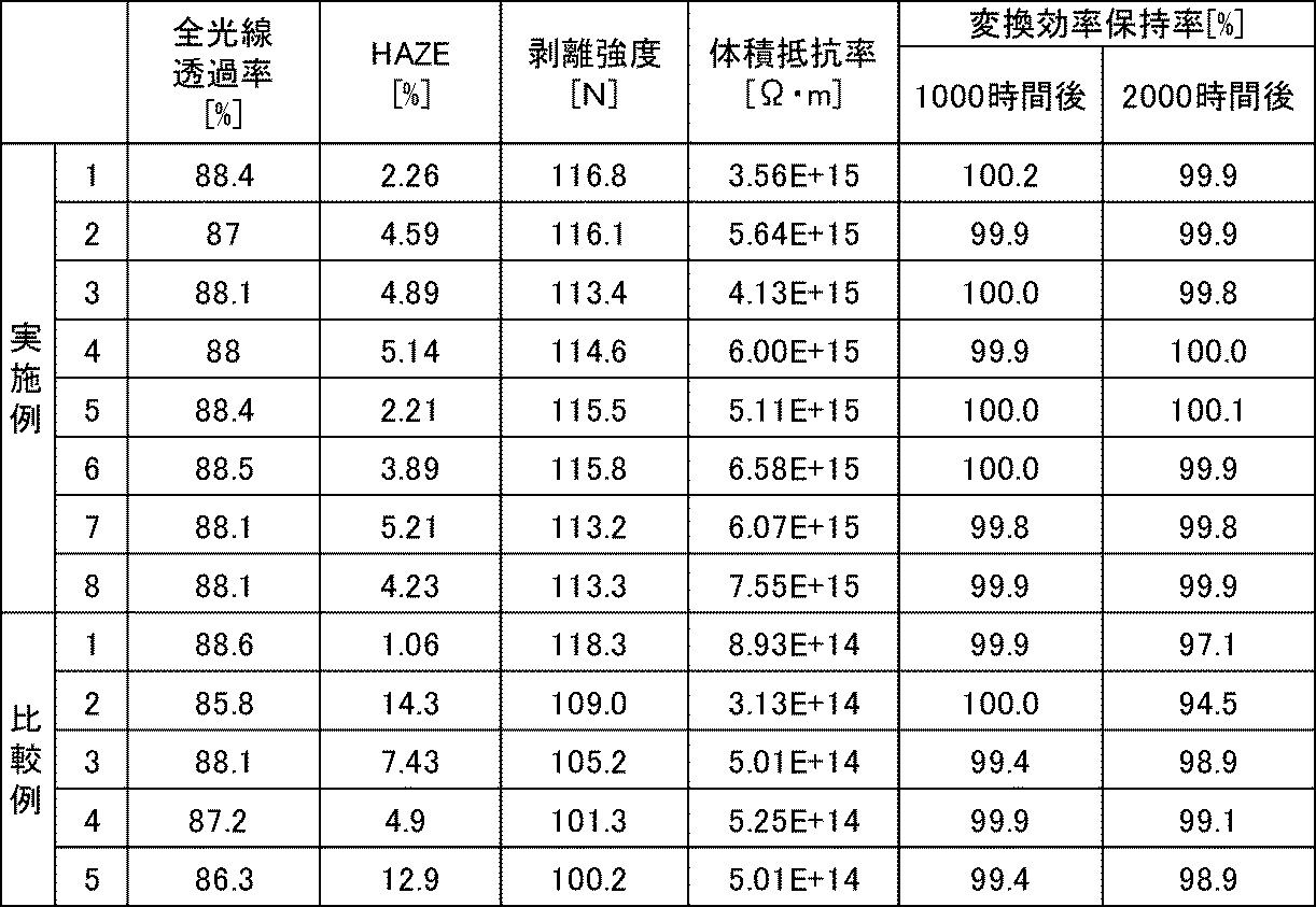
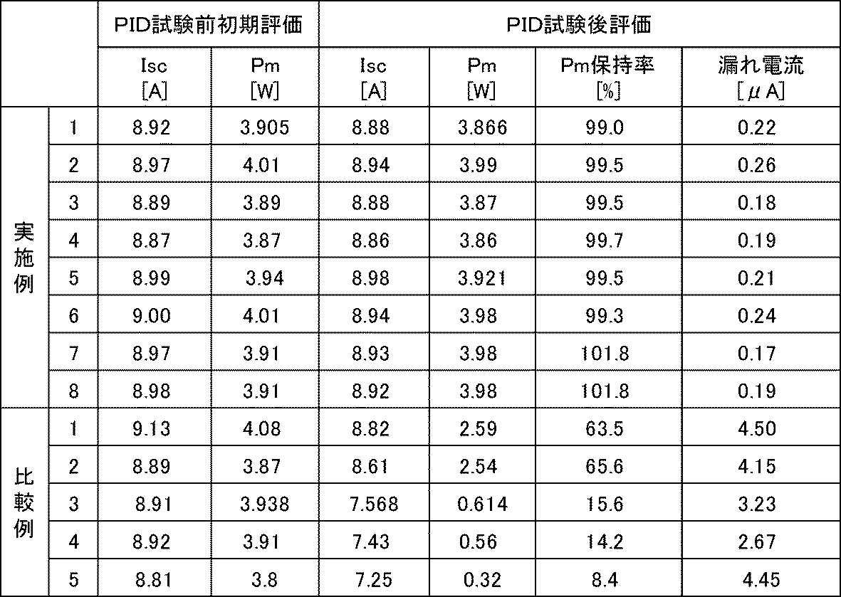
表3より、本発明の実施例においては、体積抵抗率が3.56×10¹⁵Ω・m以上の値が得られ、1015オーダーの高い体積抵抗率が得られることがわかった。一方、本発明の無機イオン捕集剤を添加しない比較例においては、体積抵抗率がいずれも1014オーダーであり、体積抵抗率が一桁低いことがわかった。
また、本実施例によれば、全光線透過率が87%以上で、且つHAZE値が5.21%以下の値が得られ、透明性に優れていることがわかった。即ち、全光線透過率として85%を超え、且つHAZE値が5.5%未満の良好な結果が得られることがわかった。一方、本発明の無機イオン捕集剤を添加しない比較例においては、全光線透過率はいずれも87%以上が得られているものの、HAZE値においては、比較例2,3,5において5.5%以上という結果であった。
また、本実施例によれば、剥離強度が113.2N以上であり、110N越えの剥離強度が得られることがわかった。一方、本発明の無機イオン捕集剤を添加しない比較例においては、イオン捕捉能を有する添加剤を加えない比較例1を除き、いずれも剥離強度が110N以下という結果を得た。
更に、本実施例によれば、2000時間後の変換効率保持率が99.8%以上であり、99%越えの結果が得られることがわかった。一方、本発明の無機イオン捕集剤を添加しない比較例においては、2000時間後の変換効率保持率がいずれも90%台を保持しているものの、本実施例より全体的に低い値であった。
表4より、本実施例は、優れた耐PID特性を有することがわかった。特にPID試験後のPm保持率および漏れ電流の評価において、比較例に比して優れた効果が得られた。具体的には、本実施例においては、PID試験後のPm保持率が99.0%以上であり、95%越えのPm保持率が得られた。これに対し、比較例においては、いずれもPm保持率が90%を下回っていた(例えば、比較例2はPm保持率が65.6%、比較例5はPm保持率が8.4%)。
また、本実施例においては、PID試験後の漏れ電流が0.26μA以下であり、0.3μA未満の結果が得られた。これに対し、比較例においては、PID試験後の漏れ電流が、最も低い比較例4においても2,67μAであり、一桁以上高い漏れ電流があることがわかった。
イオン捕捉能を有する添加剤を加えない比較例1においては、表3に示すように、透明性・剥離強度は優れるものの、PID試験後評価において問題がある。また、本発明に含まれない比較例2~5の無機イオン捕集剤(陰イオン捕捉能を有する無機イオン捕集剤)を用いた場合においては、HAZE値が低下し、密着性も低下することがわかった。また、PID試験後評価においても、本願実施例に比して劣る結果が得られた。
本願発明の無機イオン捕集剤を用いた太陽電池封止材用樹脂組成物および太陽電池封止材用マスターバッチを用いることにより、1)透明性、2)密着性、3)体積抵抗率、4)変換効率保持率、5)PID試験後評価の全てを満たす太陽電池封止材を提供できた。
この出願は、2014年1月20日に出願された日本出願特願2014-008045を基礎とする優先権を主張し、その開示の全てをここに取り込む。
11:受光面側保護ガラス
12A:(受光面側)太陽電池封止材
12B:(裏面側)太陽電池封止材
13:発電素子
14:裏面保護部材
20:積層体
21:ガラス板
22:太陽電池封止材
23:剥離性シート
24:ポリエチレンテレフタレートシート
31:受光面側保護ガラス
32A:太陽電池封止材
32B:太陽電池封止材
33:発電素子
34:裏面保護部材
35:金属フレーム
41:Isc(短絡電流)
42:Voc(開放電圧)
43:Pm(最大出力)
12A:(受光面側)太陽電池封止材
12B:(裏面側)太陽電池封止材
13:発電素子
14:裏面保護部材
20:積層体
21:ガラス板
22:太陽電池封止材
23:剥離性シート
24:ポリエチレンテレフタレートシート
31:受光面側保護ガラス
32A:太陽電池封止材
32B:太陽電池封止材
33:発電素子
34:裏面保護部材
35:金属フレーム
41:Isc(短絡電流)
42:Voc(開放電圧)
43:Pm(最大出力)
Claims (5)
- エチレン共重合体および無機イオン捕集剤を含み、
前記無機イオン捕集剤が、五価金属の酸化物、六価金属の酸化物、七価金属の酸化物、リン酸金属塩からなる群より選択する1種以上を含み、
前記エチレン共重合体100重量部に対して、前記無機イオン捕集剤を0.01~0.5重量部を含む、太陽電池封止材用樹脂組成物。 - 前記無機イオン捕集剤の平均粒子径が0.01~100μmである、請求項1記載の太陽電池封止材用樹脂組成物。
- エチレン共重合体100重量部に対して、無機イオン捕集剤を0.01~0.5重量部を含む太陽電池封止材を成形するための太陽電池封止材用マスターバッチであって、
エチレン共重合体および無機イオン捕集剤を含み、
前記無機イオン捕集剤が、五価金属の酸化物、六価金属の酸化物、七価金属の酸化物、リン酸金属塩からなる群より選択する1種以上を含み、
前記エチレン共重合体100重量部に対して、前記無機イオン捕集剤を0.01~20重量部を含む、太陽電池封止材用マスターバッチ。 - 請求項1または2項に記載の太陽電池封止材用樹脂組成物、または請求項3記載の太陽電池封止材用マスターバッチを含む混合物を成形してなる太陽電池封止材。
- 請求項4記載の太陽電池封止材を備えた太陽電池モジュール。
Priority Applications (3)
| Application Number | Priority Date | Filing Date | Title |
|---|---|---|---|
| KR1020167017776A KR101701690B1 (ko) | 2014-01-20 | 2015-01-19 | 태양전지 봉지재용 수지 조성물, 태양전지 봉지재용 마스터 배치 및 태양전지 봉지재 |
| CN201580000288.5A CN105009305B (zh) | 2014-01-20 | 2015-01-19 | 太阳能电池密封材料用树脂组合物、太阳能电池密封材料用母料以及太阳能电池密封材料 |
| SG11201506563TA SG11201506563TA (en) | 2014-01-20 | 2015-01-19 | Resin composition for solar cell sealing material, master batch for solar cell sealing material, and solar cell sealing material |
Applications Claiming Priority (2)
| Application Number | Priority Date | Filing Date | Title |
|---|---|---|---|
| JP2014-008045 | 2014-01-20 | ||
| JP2014008045A JP5648169B1 (ja) | 2014-01-20 | 2014-01-20 | 太陽電池封止材用樹脂組成物および太陽電池封止材 |
Publications (1)
| Publication Number | Publication Date |
|---|---|
| WO2015107905A1 true WO2015107905A1 (ja) | 2015-07-23 |
Family
ID=52344786
Family Applications (1)
| Application Number | Title | Priority Date | Filing Date |
|---|---|---|---|
| PCT/JP2015/000186 Ceased WO2015107905A1 (ja) | 2014-01-20 | 2015-01-19 | 太陽電池封止材用樹脂組成物、太陽電池封止材用マスターバッチおよび太陽電池封止材 |
Country Status (5)
| Country | Link |
|---|---|
| JP (1) | JP5648169B1 (ja) |
| KR (1) | KR101701690B1 (ja) |
| CN (1) | CN105009305B (ja) |
| SG (1) | SG11201506563TA (ja) |
| WO (1) | WO2015107905A1 (ja) |
Cited By (3)
| Publication number | Priority date | Publication date | Assignee | Title |
|---|---|---|---|---|
| CN112824466A (zh) * | 2019-11-19 | 2021-05-21 | 杭州福斯特应用材料股份有限公司 | 用于形成抗pid封装胶膜的组合物、抗pid封装胶膜及太阳能组件 |
| CN112898920A (zh) * | 2019-11-19 | 2021-06-04 | 杭州福斯特应用材料股份有限公司 | 用于形成抗pid封装胶膜的组合物、抗pid封装胶膜及太阳能组件 |
| KR20230119175A (ko) * | 2020-12-17 | 2023-08-16 | 다우 글로벌 테크놀로지스 엘엘씨 | 낮은 잠재적 유도 열화를 갖는 봉지재 시트 |
Families Citing this family (6)
| Publication number | Priority date | Publication date | Assignee | Title |
|---|---|---|---|---|
| WO2017175524A1 (ja) * | 2016-04-05 | 2017-10-12 | 東亞合成株式会社 | 太陽電池用イオン捕捉剤及びそれを含む太陽電池用封止剤組成物並びに太陽電池モジュール |
| CN109705442B (zh) * | 2018-12-14 | 2021-09-07 | 宁波能之光新材料科技股份有限公司 | 一种含伊/蒙粘土的光伏封装薄膜用抗pid功能母粒及其制备方法 |
| CN109705773A (zh) * | 2018-12-29 | 2019-05-03 | 乐凯胶片股份有限公司 | 聚烯烃胶膜和太阳能电池 |
| US20220389282A1 (en) * | 2019-11-19 | 2022-12-08 | Hangzhou First Applied Material Co.,Ltd. | Adhesive film, anti-PID encapsulation adhesive film, composition forming adhesive film, and photovoltaic module and laminated glass |
| CN111471405B (zh) * | 2020-04-22 | 2021-11-19 | 杭州福斯特应用材料股份有限公司 | 光伏组件封装胶膜及其制备方法 |
| CN115873514A (zh) * | 2021-09-29 | 2023-03-31 | 中国石油化工股份有限公司 | 一种抗pid型乙烯-醋酸乙烯共聚物封装胶膜及其制法和应用 |
Citations (2)
| Publication number | Priority date | Publication date | Assignee | Title |
|---|---|---|---|---|
| WO2007007671A1 (ja) * | 2005-07-07 | 2007-01-18 | Nippon Kayaku Kabushiki Kaisha | 光電変換素子用シール剤及びそれを用いた光電変換素子 |
| WO2013150730A1 (ja) * | 2012-04-06 | 2013-10-10 | 三井化学東セロ株式会社 | 太陽電池モジュール |
Family Cites Families (10)
| Publication number | Priority date | Publication date | Assignee | Title |
|---|---|---|---|---|
| JPH1154766A (ja) | 1997-07-31 | 1999-02-26 | Bridgestone Corp | 太陽電池封止材 |
| US20070267059A1 (en) * | 2004-12-28 | 2007-11-22 | Dupont-Mitsui Polychemicals Co., Ltd. | Encapsulating Material for Solar Cell |
| JP5366109B2 (ja) | 2004-12-28 | 2013-12-11 | 三井化学東セロ株式会社 | 太陽電池封止材 |
| CN101668702A (zh) * | 2007-04-26 | 2010-03-10 | 东亚合成株式会社 | 水滑石化合物及其制造方法、无机离子捕捉剂、组合物、电子部件密封用树脂组合物 |
| KR101184467B1 (ko) * | 2008-01-16 | 2012-09-19 | 히다치 가세고교 가부시끼가이샤 | 감광성 접착제 조성물, 필름상 접착제, 접착 시트, 접착제 패턴, 접착제층 부착 반도체 웨이퍼, 반도체 장치, 및, 반도체 장치의 제조방법 |
| AU2010280195A1 (en) * | 2009-08-07 | 2011-11-17 | Toyo Ink Sc Holdings Co., Ltd. | Resin composition for solar cell-sealing material |
| CN102382422B (zh) * | 2010-09-01 | 2013-01-02 | 北京科化新材料科技有限公司 | 包含一水合氧化铝的环氧树脂组合物 |
| MX340497B (es) | 2010-10-08 | 2016-07-11 | Mitsui Chemicals Inc | Material encapsulante para celda solar y modulo de celda solar. |
| US9460829B2 (en) | 2011-09-01 | 2016-10-04 | Sumitomo Chemical Company, Limited | Resin composition, resin pellet, method for producing resin pellet, and solar cell encapsulant |
| CN103254802B (zh) * | 2013-03-19 | 2015-06-03 | 江苏鹿山光伏科技有限公司 | 一种抗光伏组件潜在电势诱导衰减的eva封装胶膜 |
-
2014
- 2014-01-20 JP JP2014008045A patent/JP5648169B1/ja active Active
-
2015
- 2015-01-19 KR KR1020167017776A patent/KR101701690B1/ko active Active
- 2015-01-19 CN CN201580000288.5A patent/CN105009305B/zh active Active
- 2015-01-19 SG SG11201506563TA patent/SG11201506563TA/en unknown
- 2015-01-19 WO PCT/JP2015/000186 patent/WO2015107905A1/ja not_active Ceased
Patent Citations (2)
| Publication number | Priority date | Publication date | Assignee | Title |
|---|---|---|---|---|
| WO2007007671A1 (ja) * | 2005-07-07 | 2007-01-18 | Nippon Kayaku Kabushiki Kaisha | 光電変換素子用シール剤及びそれを用いた光電変換素子 |
| WO2013150730A1 (ja) * | 2012-04-06 | 2013-10-10 | 三井化学東セロ株式会社 | 太陽電池モジュール |
Cited By (5)
| Publication number | Priority date | Publication date | Assignee | Title |
|---|---|---|---|---|
| CN112824466A (zh) * | 2019-11-19 | 2021-05-21 | 杭州福斯特应用材料股份有限公司 | 用于形成抗pid封装胶膜的组合物、抗pid封装胶膜及太阳能组件 |
| CN112898920A (zh) * | 2019-11-19 | 2021-06-04 | 杭州福斯特应用材料股份有限公司 | 用于形成抗pid封装胶膜的组合物、抗pid封装胶膜及太阳能组件 |
| KR20230119175A (ko) * | 2020-12-17 | 2023-08-16 | 다우 글로벌 테크놀로지스 엘엘씨 | 낮은 잠재적 유도 열화를 갖는 봉지재 시트 |
| EP4263699A4 (en) * | 2020-12-17 | 2024-10-30 | Dow Global Technologies LLC | ENCAPSULATION FILM WITH LOW POTENTIAL INDUCED DEGRADATION |
| KR102885501B1 (ko) | 2020-12-17 | 2025-11-13 | 다우 글로벌 테크놀로지스 엘엘씨 | 낮은 잠재적 유도 열화를 갖는 봉지재 시트 |
Also Published As
| Publication number | Publication date |
|---|---|
| CN105009305B (zh) | 2017-03-15 |
| CN105009305A (zh) | 2015-10-28 |
| KR101701690B1 (ko) | 2017-02-01 |
| SG11201506563TA (en) | 2015-09-29 |
| JP5648169B1 (ja) | 2015-01-07 |
| JP2015138805A (ja) | 2015-07-30 |
| KR20160085911A (ko) | 2016-07-18 |
Similar Documents
| Publication | Publication Date | Title |
|---|---|---|
| JP5648169B1 (ja) | 太陽電池封止材用樹脂組成物および太陽電池封止材 | |
| JP6428199B2 (ja) | 太陽電池封止材用樹脂組成物、並びにそれを用いた太陽電池封止材及び太陽電池モジュール | |
| EP2808906B1 (en) | Sealing film for solar cells, and solar cell using same | |
| JP5914323B2 (ja) | 太陽電池用封止膜及びこれを用いた太陽電池 | |
| JP5416345B2 (ja) | 太陽電池用封止膜の製造方法 | |
| JP2015211189A (ja) | 太陽電池封止材用樹脂組成物、並びにそれを用いた太陽電池封止材及び太陽電池モジュール | |
| JP6152099B2 (ja) | 太陽電池モジュール | |
| CN103636003B (zh) | 太阳能电池用密封膜和使用其的太阳能电池 | |
| JP2011155238A (ja) | 太陽電池封止材用樹脂組成物 | |
| WO2010140608A1 (ja) | 太陽電池用封止膜及びこれを用いた太陽電池 | |
| JP5821341B2 (ja) | 太陽電池封止材用樹脂組成物、及びそれを用いた太陽電池封止材 | |
| JP5565520B1 (ja) | 太陽電池封止材用樹脂組成物、太陽電池封止材および太陽電池モジュール | |
| EP2770541B1 (en) | Solar cell sealing film and solar cell using same | |
| JP2012195561A (ja) | 太陽電池モジュール用封止材シート | |
| WO2011016233A1 (ja) | 太陽電池封止材用樹脂組成物 | |
| JP2015162498A (ja) | 太陽電池封止材用積層体、太陽電池封止材及び太陽電池モジュール | |
| JP4702495B1 (ja) | 太陽電池封止材用樹脂組成物 | |
| JP5869211B2 (ja) | 太陽電池用封止膜及びこれを用いた太陽電池 | |
| EP4079520B1 (en) | Resin composition for solar cell sealing material, solar cell sealing material, method for producing solar cell sealing material, and solar cell module | |
| JP5865293B2 (ja) | 太陽電池用封止膜の製造方法及び太陽電池用封止膜 | |
| JP2012019179A (ja) | 太陽電池封止材用樹脂組成物 | |
| CN107429013A (zh) | 密封片以及太阳能电池模块 |
Legal Events
| Date | Code | Title | Description |
|---|---|---|---|
| 121 | Ep: the epo has been informed by wipo that ep was designated in this application |
Ref document number: 15737747 Country of ref document: EP Kind code of ref document: A1 |
|
| ENP | Entry into the national phase |
Ref document number: 20167017776 Country of ref document: KR Kind code of ref document: A |
|
| NENP | Non-entry into the national phase |
Ref country code: DE |
|
| 122 | Ep: pct application non-entry in european phase |
Ref document number: 15737747 Country of ref document: EP Kind code of ref document: A1 |