WO2015107731A1 - Machine pour travaux - Google Patents
Machine pour travaux Download PDFInfo
- Publication number
- WO2015107731A1 WO2015107731A1 PCT/JP2014/076944 JP2014076944W WO2015107731A1 WO 2015107731 A1 WO2015107731 A1 WO 2015107731A1 JP 2014076944 W JP2014076944 W JP 2014076944W WO 2015107731 A1 WO2015107731 A1 WO 2015107731A1
- Authority
- WO
- WIPO (PCT)
- Prior art keywords
- prime mover
- working machine
- engine
- operating rod
- operation rod
- Prior art date
Links
Images


Classifications
-
- A—HUMAN NECESSITIES
- A01—AGRICULTURE; FORESTRY; ANIMAL HUSBANDRY; HUNTING; TRAPPING; FISHING
- A01D—HARVESTING; MOWING
- A01D34/00—Mowers; Mowing apparatus of harvesters
- A01D34/835—Mowers; Mowing apparatus of harvesters specially adapted for particular purposes
- A01D34/90—Mowers; Mowing apparatus of harvesters specially adapted for particular purposes for carrying by the operator
- A01D34/905—Vibration dampening means
Definitions
- the present invention relates to a working machine such as a brush cutter that rotates a rotary tool by a prime mover, and more particularly, to a working machine provided with a prime mover at a rear end portion of an operating rod having a gripping part that a worker grips.
- Patent Document 1 discloses a brush cutter for cutting grass, turf, and the like.
- This brush cutter has an operating rod attached with a handle gripped by an operator, an engine-type prime mover provided at the rear end portion of the operating rod, a rotary blade provided at the front end portion of the operating rod and rotated by the prime mover, And a power transmission shaft that is rotatably supported in the operating rod and transmits the drive of the prime mover to the rotary blade.
- the rotary blade is rotated by the driving force transmitted from the prime mover by the power transmission shaft, and the operator operates the handle to move the rotary blade parallel to the ground. This cuts the grass and grass that grows from the ground.
- An object of the present invention is to make it difficult for vibration of a prime mover to be transmitted to a grip portion of an operating rod and to make an operator who grips the grip portion of an operating rod less likely to get tired due to vibration.
- the present invention provides an operating rod having a gripping portion to be gripped by an operator, a prime mover provided at the rear end portion of the operating rod, and a front end portion of the operating rod that is rotated by the prime mover.
- a mounting frame that mounts the prime mover is integrated at the rear end of the operating rod
- an elastic member for supporting the prime mover in a vibration-proof manner is provided on the mount frame.
- the mount frame on which the prime mover is mounted is integrally fixed to the rear end portion of the operation rod, and the mount frame is provided with an elastic member that supports the prime mover in a vibration-proof manner.
- This vibration is less likely to be transmitted to the operating rod with the mount frame fixed by the elastic member, and even if the operator grips the grip portion provided on the operating rod, the vibration does not easily cause fatigue.
- the mount frame has an upright portion that is fixed to the rear end portion of the operating rod and extends up and down, and a pedestal portion that extends rearward from the lower end of the upright portion.
- the elastic member provided between the rear surface of the standing portion and the front portion of the prime mover employs a compression spring extending in the front-rear direction, and the elastic member provided between the upper surface of the base part and the lower part of the prime mover extends in the vertical direction.
- a compression spring should be used.
- the present invention provides an operating rod having a gripping portion to be gripped by an operator, a prime mover provided at a rear end portion of the operating rod, and a prime mover provided at a front end portion of the operating rod. And a support body fixed to the outer peripheral portion of the operation rod, and a support that is rotatably supported in the operation ⁇ and a power transmission shaft that transmits the drive of the prime mover to the rotary tool.
- a working machine comprising a dynamic vibration absorber having a mass body spaced apart from the outside of the body and an elastic body that swingably supports the mass body with respect to a support body. Is.
- the dynamic vibration absorber reduces the vibration transmitted to the operating rod by swinging the mass body so as to cancel the vibration caused by the driving of the prime mover and the rotation of the power transmission shaft,
- the vibration of the grip portion of the heel is also suppressed.
- the elastic body supports the mass body so as to be swingable in three degrees of freedom of translation and three degrees of rotation relative to the support body. In this case, the prime mover vibrates in any direction.
- this dynamic vibration absorber can be used with any prime mover that vibrates in any direction, this dynamic vibration absorber can be used in various types of work machines that have different vibration directions depending on the arrangement and specifications of the prime mover. It was possible and the versatility of this dynamic vibration absorber could be increased.
- a dynamic vibration absorber is provided between the prime mover and the gripping portion.
- the dynamic vibration absorber is used before the vibration of the prime mover is transmitted to the gripping portion. Vibration can be reduced, and the vibration of the prime mover is less likely to be transmitted to the gripping part.
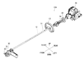
- the brush cutter 10 is provided with a long and narrow cylindrical operation rod 11 extending in the front-rear direction, an engine (prime mover) 20 at the rear end portion of the operation rod 11, and a front end portion of the operation rod 11. And a cutter unit 30 having a rotary blade (rotary tool) 32 that is rotated by the engine 20. Further, a power transmission shaft 12 that transmits the drive of the engine 20 to the rotary blade 32 is rotatably supported in the operation rod 11 via a bearing member.
- a loop handle (gripping part) 13 having a loop shape is provided in the middle part in the front-rear direction of the operation rod 11, and a grip handle (gripping part) 14 is provided on the rear side of the loop handle 13.
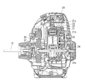
- the engine 20 includes a cylinder block 21 in which a crankcase 21a and a cylinder 21b are integrally provided at a lower portion, and a piston 22 can reciprocate in the vertical direction in the cylinder block 21. Contained.
- a combustion chamber 23 is formed between the upper surface of the piston 22 and the cylinder head 21 c at the upper end of the cylinder block 21.
- the cylinder head 21c is provided with an intake port that guides the air-fuel mixture generated by the carburetor to the combustion chamber 23 and an exhaust port that guides the exhaust gas generated in the combustion chamber 23 to the exhaust muffler (both not shown).
- a crankshaft 24 is provided in the crankcase 21a, and the crankshaft 24 is supported so as to be rotatable about an axis whose front-rear direction is an axial direction.
- a piston 22 is connected to the crankshaft 24 via a connecting rod 25, and the reciprocating motion of the piston 22 in the vertical direction is converted into the rotational motion of the crankshaft 24.
- a flywheel 26 is provided at the front end of the crankshaft 24, and the flywheel 26 has a function of stabilizing the rotation of the crankshaft 24 and cooling the inside of the engine 20.
- a centrifugal clutch 27 is provided at the front end of the crankshaft 24 on the front side of the flywheel 26. The centrifugal clutch 27 allows the crankshaft 24 to rotate when the rotational speed of the crankshaft 24 exceeds a predetermined value. It is transmitted to the power transmission shaft 12.
- the cutter unit 30 includes a front end housing 31 fixed to the front end portion of the operation rod 11, and a rotating shaft (not shown) is rotatably supported by the front end housing 31.
- a bevel gear (not shown) is fixed to the base end portion of the rotation shaft, and the bevel gear fixed to the front end portion of the power transmission shaft 12 is engaged with the bevel gear, and the rotation of the power transmission shaft 12 causes the bevel gear to rotate. Is transmitted to the rotating shaft.
- the tip of the rotating shaft protrudes below the front end housing 31, and a rotary blade 32 is attached to the tip of the rotating shaft.
- the rotary blade 32 of this embodiment uses a nylon cord, it may use a disk-shaped rotary blade having a blade portion on the outer peripheral portion.
- the mount frame 40 is fixed to the rear end of the operation rod 11, and the engine 20 is mounted on the mount frame 40 in a vibration-proof manner.
- the mount frame 40 includes an upright portion 41 that is fixed to the rear end portion of the operation rod 11 and extends up and down, and a pedestal portion 42 that extends rearward from the lower end of the upright portion 41.
- the mount frame 40 is provided with a pair of left and right first compression springs (elastic members) 43 between the rear surface of the upright portion 41 and the front portion of the engine 20, and the upper surface rear portion of the pedestal portion 42 and the rear lower portion of the engine 20.
- a pair of left and right second compression springs (elastic members) 44 are provided between them.
- the first compression spring 43 extends in the front-rear direction, and supports the engine 20 so that it can expand and contract in the front-rear direction and swing in directions crossing the front-rear direction (vertical direction and left-right direction).
- the second compression spring 44 extends in the vertical direction, and supports the engine 20 so that it can expand and contract in the vertical direction and swing in directions intersecting the vertical direction (front-rear direction and left-right direction).
- the crankshaft 24 when the engine 20 is driven, the crankshaft 24 is rotated by the piston 22 reciprocating in the vertical direction, and the crankshaft 24 is connected to the power transmission shaft 12 by the centrifugal clutch 27. Then, the power transmission shaft 12 is rotated, and the rotation of the power transmission shaft 12 is transmitted to the rotation shaft through the pair of bevel gears in the front end housing 31, and the rotary blade 32 fixed to the rotation shaft rotates.
- the operator holds the loop handle 13 with one hand and the grip handle 14 with the other hand, and operates the handles 13 and 14 to swing the rotary blade 32 left and right along the upper side of the ground. Grass, grass, etc. growing from the ground are cut off.
- the mount frame 40 on which the engine 20 is mounted is fixed integrally to the rear end portion of the operation rod 11, and the first and second are supported on the mount frame 40 in a vibration-proof manner.
- Compression springs 43 and 44 are provided.
- the mount frame 40 includes an upright portion 41 that is fixed to the rear end portion of the operating rod 11 and extends up and down, and a pedestal portion 42 that extends rearward from the lower end of the upright portion 41.
- a pair of left and right first compression springs 43 are provided between the rear surface and the front portion of the engine 20, and a pair of left and right second compression springs 44 are provided between the upper surface rear portion of the pedestal portion 42 and the rear lower portion of the engine 20. It was.
- the first compression spring 43 supports the engine 20 such that it can expand and contract in the front-rear direction and swing in the direction intersecting with the front-rear direction (vertical direction and left-right direction), and the second compression spring 44 can be expanded and contracted in the vertical direction
- the engine 20 is supported so as to be swingable in the direction intersecting with (the front-rear direction and the left-right direction).
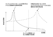
- the engine 20 and the mount frame 40 are connected to each other.
- the natural frequency of the vibration system composed of the second compression springs 43 and 44 can be greatly separated from the frequency generated from the vibration of the engine 20, and transmission of the vibration generated by the drive of the engine 20 can be reduced.
- the vibration of the engine 20 is not easily transmitted to the operating rod 11 with the mount frame 40 fixed by the first and second compression springs 43 and 44, and the operator holds the handles 13 and 14 provided on the operating rod 11. Even so, it became hard to get tired by vibration.
- the power transmission shaft 12 in the operation rod 11 rotates by driving the engine 20, and vibration due to the rotation of the power transmission shaft 12 may be transmitted to the operation rod 11, but the power transmission shaft 12 is covered in the operation rod 11. If an elongated tube (pipe member) is interposed and the tube is interposed in the operation rod 11 via a flexible elastic member such as rubber, it is possible to suppress the vibration of the power transmission shaft 12 from being transmitted to the operation rod 11.
- the power transmission shaft 12 is not limited to a long rod-shaped shaft member, and may be one using a flexible long shaft member such as a flexible shaft.
- a long shaft member When a long shaft member is used, vibration may occur due to rotation of the power transmission shaft 12, but vibration can be suppressed by a flexible elastic member interposed outside the tube.
- a flexible elastic member such as rubber is interposed between the operation rod 11 and the handles 13 and 14. It is also possible to suppress vibration from being transmitted from the operation rod 11 to the handles 13 and 14. However, in this case, the handles 13 and 14 may be swayed by the flexible elastic member interposed between the operation rod 11 and the operability of the handles 13 and 14 may be reduced.
- each handle 13 Since it is not necessary to interpose a flexible elastic member such as rubber between the operation lever 11 and the operation rod 11, the handles 13 and 14 can be fixed to the operation rod 11 in a stable state. It was possible to reduce both the transmitted vibration and maintain the operability of the handles 13 and 14.
- the compression springs 43 and 44 are employed as the elastic members.
- the other elastic members may be a flexible spring such as a leaf spring, a cylindrical or columnar rubber, or the like.
- a body, an air spring, or the like may be employed, and even when this is done, the same effects as described above can be obtained.
- the operation rod 11 uses a straight cylindrical tube member, but the present invention is not limited to this, and uses a bent tube member having a curved tip. In this way, the same effect can be obtained.
- the brush cutter using the loop handle 13 and the grip handle 14 as the grip portion has been described.
- the present invention is not limited to this, and only one of the loop handle 13 and the grip handle 14 is used. The same effect can be obtained even with a brush cutter that employs a U-shaped handle instead of the employed brush cutter or the loop handle 13 and the grip handle 14.
- a brush cutter using a rotary blade as a rotary tool has been described.
- the working machine of the present invention is not limited to this, and a polisher such as a polisher or a grinder using a polisher as a rotary tool. It can be applied to the above.
- the prime mover 20 substantially the same as the prime mover 20 in the first embodiment described above is directly assembled to the rear end portion of the operating rod 11, and the dynamic vibration absorber 50 described later is connected to the prime mover 20 and the grip handle (gripping part). ), And the other components are the same as those in the first embodiment. Therefore, the same members and the same parts are denoted by the same reference numerals, and the description thereof is as follows. Omitted.
- the operating rod 11 having the grip portions 13 and 14 that the operator grips, the prime mover 20 provided at the rear end portion of the operating rod 11, and the front end portion of the operating rod 11
- a working machine provided with a rotary tool 32 that is provided and rotated by a prime mover, and a power transmission shaft 12 that is rotatably supported in the operation rod 11 and transmits the drive of the prime mover 20 to the rotary tool 32
- a support body 51 fixed to the outer periphery, a mass body 52 spaced apart from the outside of the support body 51, and an elastic body 55 that supports the mass body 52 so as to be swingable with respect to the support body 51.
- the working machine 10A is provided with the dynamic vibration absorber 50 provided.
- the operating rod 11 is provided with a dynamic vibration absorber 50, and the dynamic vibration absorber 50 is mainly for reducing vibration transmitted from the engine 20 to the operating rod 11. .
- the dynamic vibration absorber 50 is disposed between the grip handle 14 and the engine 20 at the rear portion of the operation rod 11.
- the dynamic vibration absorber 50 includes a support body 51 fixed to the outer peripheral portion of the rear part of the operation rod 11, a mass body 52 that is spaced apart from the support body 51, and a mass body 52 that swings the mass body 52 relative to the support body 51. And an elastic body 55 that is movably supported.
- the support 51 has a short cylindrical shape, and eight mounting holes 51 a extending in the radial direction are formed at equal intervals in the circumferential direction on the periphery of the support 51. These mounting holes 51a are for mounting the elastic body 55, and are stepped holes in which two cylindrical holes having a large outer peripheral side and a small inner peripheral side are arranged concentrically.
- the mass body 52 has a short cylindrical inner portion 53 having a larger diameter than the support 51 and a short cylindrical outer portion 54 fitted to the outer peripheral surface of the inner portion 53.
- the outer portion 54 is a structure using a metal member such as stainless steel. Eight through holes 53a extending in the radial direction are formed at equal positions in the circumferential direction at positions facing the mounting holes 51a of the support body 51 in the inner portion 53 of the mass body 52, and these through holes 53a are elastic bodies.
- the elastic body 55 is attached to the mass body 52 by accommodating the middle part to the front end of 55.
- the outer portion 54 is fitted so as to cover the inner portion 53 from the outside, and is fixed to the inner portion 53 with screws.
- the outer portion 54 is provided with a through hole 54a having a smaller diameter than the through hole 53a at a position facing the through hole 53a of the inner portion 53, and the elastic body 55 is prevented from being detached by the peripheral portion of the through hole 54a.
- the elastic body 55 is for supporting the mass body 52 on the support body 51 so as to be swingable in a state where the mass body 52 is concentrically spaced from the support body 51.
- the elastic body 55 is made of a flexible elastic member such as rubber having a cylindrical shape.
- the elastic body 55 is mounted with its base end positioned in the mounting hole 51a of the support 51 in a state where the base end is secured by the bottom of the mounting hole 51a of the support 51, and the tip is attached to the outer portion of the mass body 52. In a state where it is prevented from being detached by 54, the tip side from the intermediate part is positioned and attached in the through hole 53 a of the inner part 53 of the mass body 52.
- the mass body 52 is supported by the eight elastic bodies 55 so as to be swingable with respect to the support body 51 with six degrees of freedom of three translational degrees of freedom and three degrees of freedom of rotation.
- the elastic body 55 is not limited to a flexible elastic member such as rubber, and may be one using a spring member such as a coil spring. In this embodiment, eight elastic bodies 55 are arranged at equal intervals in the circumferential direction. However, the present invention is not limited to this, and three or more elastic bodies 55 may be arranged at equal intervals. Further, the shape is not limited to a cylinder, and the support body 51 and the mass body 52 may be joined (for example, integrally molded) with an elastic body such as a whole circumference rubber.
- the crankshaft 24 is rotated by the piston 22 reciprocating in the vertical direction, and the crankshaft 24 is connected to the power transmission shaft 12 by the centrifugal clutch 27. Then, the power transmission shaft 12 is rotated, and the rotation of the power transmission shaft 12 is transmitted to the rotation shaft through the pair of bevel gears, and the rotary blade 32 fixed to the rotation shaft rotates.
- the operator holds the loop handle 13 with one hand and the grip handle 14 with the other hand, and operates the handles 13 and 14 to swing the rotary blade 32 left and right along the upper side of the ground. Grass, grass, etc. growing from the ground are cut off.
- the brush cutter 10 ⁇ / b> A includes a support body 51 fixed to the outer periphery of the operation rod 11, a mass body 52 that is spaced apart from the outside of the support body 51, and a mass body that rocks the support body 51.
- a dynamic vibration absorber 50 having an elastic body 55 that is movably supported is provided.
- the dynamic vibration absorber 50 is provided on the operation rod 11 by reducing the vibration transmitted to the operation rod 11 by swinging the mass body 52 so as to reduce the vibration caused by the driving of the engine 20 and the rotation of the power transmission shaft 12.
- the vibration of the loop handle 13 and the grip handle 14 is also suppressed.
- the vibration generated in the loop handle 13 is a vibration in the vertical direction as compared with the case where no dynamic vibration absorber is provided.
- the vibration generated in the grip handle 14 is about 8% in the left-right direction, about 9% in the front-rear direction, and about 14% in the up-down direction compared to the case without the dynamic vibration absorber. It was possible to greatly suppress. As a result, even if the operator grips the loop handle 13 and the grip handle 14, it is less likely to get tired due to vibration generated in the engine 20 or the like.
- the dynamic vibration absorber 50 is configured such that the mass body 52 is supported by the support body 51 by the elastic body 55 so that the mass body 52 can swing freely in 6 degrees of freedom of translation and 3 degrees of rotation.
- the mass body 52 does not cause the mass body 52 even when complicated vibrations are caused due to a plurality of vibrations such as when the front-rear direction is vibrated in a direction rotating around the axis. Even if the operator grips the handles 13 and 14 by swinging so as to reduce these vibrations, it becomes hard to get tired.
- this dynamic vibration absorber 50 is adopted in a brush cutter of a model in which the direction of vibration differs depending on the arrangement and specifications of the engine 20, for example, when the piston 22 is inclined from an upright state, The vibration transmitted to the operation rod 11 can be suppressed, and the versatility of the dynamic vibration absorber 50 can be increased.
- the dynamic vibration absorber 50 is provided between the engine 20 and the grip handle 14 (including the loop handle 13).
- the dynamic vibration absorber 50 can reduce the vibration transmitted from the engine 20 to the operating rod 11 before transmitting it to the grip handle 14 and the loop handle 13, and the vibration of the engine 20 is reduced to the grip handle 14 and the loop handle 13. It became more difficult to communicate.
- the dynamic vibration absorber 50 is optimally provided between the engine 20 of the operating rod 11 and the grip handle 14 (including the loop handle 13), but is not limited to this.
- the dynamic vibration absorber 50 is provided. Even if it is provided between the loop handle 13 and the grip handle 14 of the operating rod 11 or in front of the loop handle 13, the vibration transmitted from the engine 20 to the operating rod 11 can be reduced.
- a flexible elastic member such as rubber is interposed between the operation rod 11 and the handles 13 and 14. It is also possible to suppress vibration from being transmitted from the operation rod 11 to the handles 13 and 14. However, in this case, the handles 13 and 14 may be swayed by the flexible elastic member interposed between the operation rod 11 and the operability of the handles 13 and 14 may be reduced.
- a flexible elastic member such as rubber needs to be interposed between the handles 13 and 14 and the operation rod 11. Therefore, the handles 13 and 14 can be fixed to the operation rod 11 in a stable state, vibrations transmitted to the handles 13 and 14 can be reduced, and the operability of the handles 13 and 14 can be maintained. I was able to balance both.
- the brush cutter using the loop handle 13 and the grip handle 14 as the grip portion has been described.
- the present invention is not limited to this, and only one of the loop handle 13 and the grip handle 14 is used. The same effect can be obtained even with a brush cutter that employs a U-shaped handle instead of the employed brush cutter or the loop handle 13 and the grip handle 14.
Landscapes
- Life Sciences & Earth Sciences (AREA)
- Environmental Sciences (AREA)
- Harvester Elements (AREA)
Abstract
L'invention a pour objet de réduire la probabilité que des vibrations provenant d'un moteur ne soient transmises à une section poignée d'un pôle fonctionnel et de réduire la probabilité qu'un travailleur saisissant la section poignée du pôle fonctionnel ne fatigue en raison des vibrations. La machine pour travaux (10) selon l'invention comprend un pôle fonctionnel (11) qui comporte une section poignée qui est saisie par un travailleur, un moteur (20) disposé sur la section d'extrémité arrière du pôle fonctionnel (11), un outil rotatif (32) qui est disposé sur la section d'extrémité avant du pôle fonctionnel (11) et qui est entraîné en rotation par le moteur (20) et un arbre de transmission de puissance (12) qui est porté en rotation à l'intérieur du pôle fonctionnel (11) et qui transmet l'entraînement du moteur (20) à l'outil rotatif (32). Un bâti (40) sur lequel le moteur (20) est monté est fixé d'une seule pièce à la section d'extrémité arrière du pôle fonctionnel (11) et le bâti (40) est doté d'éléments élastiques (43, 44) qui portent le moteur (20) de manière à empêcher les vibrations.
Applications Claiming Priority (4)
| Application Number | Priority Date | Filing Date | Title |
|---|---|---|---|
| JP2014004417A JP2015130831A (ja) | 2014-01-14 | 2014-01-14 | 作業機 |
| JP2014-004417 | 2014-01-14 | ||
| JP2014004426A JP6081384B2 (ja) | 2014-01-14 | 2014-01-14 | 作業機 |
| JP2014-004426 | 2014-01-14 |
Publications (1)
| Publication Number | Publication Date |
|---|---|
| WO2015107731A1 true WO2015107731A1 (fr) | 2015-07-23 |
Family
ID=53542642
Family Applications (1)
| Application Number | Title | Priority Date | Filing Date |
|---|---|---|---|
| PCT/JP2014/076944 WO2015107731A1 (fr) | 2014-01-14 | 2014-10-08 | Machine pour travaux |
Country Status (1)
| Country | Link |
|---|---|
| WO (1) | WO2015107731A1 (fr) |
Cited By (1)
| Publication number | Priority date | Publication date | Assignee | Title |
|---|---|---|---|---|
| US11202798B2 (en) | 2010-07-22 | 2021-12-21 | Reven Pharmaceuticals, Inc. | Method of treating or ameliorating skin conditions with a magnetic dipole stabilized solution |
Citations (5)
| Publication number | Priority date | Publication date | Assignee | Title |
|---|---|---|---|---|
| JPS4881015U (fr) * | 1972-01-17 | 1973-10-03 | ||
| JPS4925058Y1 (fr) * | 1970-04-15 | 1974-07-05 | ||
| JPS533228U (fr) * | 1976-06-26 | 1978-01-12 | ||
| JPS5610845A (en) * | 1979-07-09 | 1981-02-03 | Uchiumi Fujio | Handle apparatus |
| JPS5625848U (fr) * | 1979-08-03 | 1981-03-10 |
-
2014
- 2014-10-08 WO PCT/JP2014/076944 patent/WO2015107731A1/fr active Application Filing
Patent Citations (5)
| Publication number | Priority date | Publication date | Assignee | Title |
|---|---|---|---|---|
| JPS4925058Y1 (fr) * | 1970-04-15 | 1974-07-05 | ||
| JPS4881015U (fr) * | 1972-01-17 | 1973-10-03 | ||
| JPS533228U (fr) * | 1976-06-26 | 1978-01-12 | ||
| JPS5610845A (en) * | 1979-07-09 | 1981-02-03 | Uchiumi Fujio | Handle apparatus |
| JPS5625848U (fr) * | 1979-08-03 | 1981-03-10 |
Cited By (1)
| Publication number | Priority date | Publication date | Assignee | Title |
|---|---|---|---|---|
| US11202798B2 (en) | 2010-07-22 | 2021-12-21 | Reven Pharmaceuticals, Inc. | Method of treating or ameliorating skin conditions with a magnetic dipole stabilized solution |
Similar Documents
| Publication | Publication Date | Title |
|---|---|---|
| US9148997B2 (en) | Work apparatus | |
| JP6681226B2 (ja) | チェーンソー | |
| CN1846473B (zh) | 手持式自由切削机 | |
| JP4537600B2 (ja) | 刈払機の操作杆 | |
| JP2013151055A (ja) | 打撃工具 | |
| US20210086276A1 (en) | Power tool | |
| US20050198835A1 (en) | Bush cutting machine | |
| GB2430638A (en) | Vibration damping in rotary power tools | |
| WO2015107731A1 (fr) | Machine pour travaux | |
| JP5536547B2 (ja) | 携帯型動力作業機 | |
| EP1530890B1 (fr) | Outil portable à manette amortie pour usage jardinier et agricole | |
| JP3778422B2 (ja) | 刈払機 | |
| JP6081384B2 (ja) | 作業機 | |
| JP2014018183A (ja) | 刈込機 | |
| JP2015130831A (ja) | 作業機 | |
| JP2020536558A (ja) | 電動式草木カッター | |
| JP6076165B2 (ja) | 可搬式作業機の防振装置 | |
| JP2013078268A (ja) | 刈払機 | |
| JP4212080B2 (ja) | 携帯式作業機 | |
| JP2019122354A (ja) | 刈払機のハンドル防振装置 | |
| JP2015202064A (ja) | 携帯型作業機 | |
| JP2021112178A (ja) | 刈払機の防振装置 | |
| JP2006014677A (ja) | 角度可変伝動操作桿装置 | |
| JP6454501B2 (ja) | 背負い式作業機 | |
| JP2016187854A (ja) | 動力工具 |
Legal Events
| Date | Code | Title | Description |
|---|---|---|---|
| 121 | Ep: the epo has been informed by wipo that ep was designated in this application |
Ref document number: 14878431 Country of ref document: EP Kind code of ref document: A1 |
|
| NENP | Non-entry into the national phase |
Ref country code: DE |
|
| 122 | Ep: pct application non-entry in european phase |
Ref document number: 14878431 Country of ref document: EP Kind code of ref document: A1 |