WO2015107731A1 - Work machine - Google Patents
Work machine Download PDFInfo
- Publication number
- WO2015107731A1 WO2015107731A1 PCT/JP2014/076944 JP2014076944W WO2015107731A1 WO 2015107731 A1 WO2015107731 A1 WO 2015107731A1 JP 2014076944 W JP2014076944 W JP 2014076944W WO 2015107731 A1 WO2015107731 A1 WO 2015107731A1
- Authority
- WO
- WIPO (PCT)
- Prior art keywords
- prime mover
- working machine
- engine
- operating rod
- operation rod
- Prior art date
Links
Images


Classifications
-
- A—HUMAN NECESSITIES
- A01—AGRICULTURE; FORESTRY; ANIMAL HUSBANDRY; HUNTING; TRAPPING; FISHING
- A01D—HARVESTING; MOWING
- A01D34/00—Mowers; Mowing apparatus of harvesters
- A01D34/835—Mowers; Mowing apparatus of harvesters specially adapted for particular purposes
- A01D34/90—Mowers; Mowing apparatus of harvesters specially adapted for particular purposes for carrying by the operator
- A01D34/905—Vibration dampening means
Definitions
- the present invention relates to a working machine such as a brush cutter that rotates a rotary tool by a prime mover, and more particularly, to a working machine provided with a prime mover at a rear end portion of an operating rod having a gripping part that a worker grips.
- Patent Document 1 discloses a brush cutter for cutting grass, turf, and the like.
- This brush cutter has an operating rod attached with a handle gripped by an operator, an engine-type prime mover provided at the rear end portion of the operating rod, a rotary blade provided at the front end portion of the operating rod and rotated by the prime mover, And a power transmission shaft that is rotatably supported in the operating rod and transmits the drive of the prime mover to the rotary blade.
- the rotary blade is rotated by the driving force transmitted from the prime mover by the power transmission shaft, and the operator operates the handle to move the rotary blade parallel to the ground. This cuts the grass and grass that grows from the ground.
- An object of the present invention is to make it difficult for vibration of a prime mover to be transmitted to a grip portion of an operating rod and to make an operator who grips the grip portion of an operating rod less likely to get tired due to vibration.
- the present invention provides an operating rod having a gripping portion to be gripped by an operator, a prime mover provided at the rear end portion of the operating rod, and a front end portion of the operating rod that is rotated by the prime mover.
- a mounting frame that mounts the prime mover is integrated at the rear end of the operating rod
- an elastic member for supporting the prime mover in a vibration-proof manner is provided on the mount frame.
- the mount frame on which the prime mover is mounted is integrally fixed to the rear end portion of the operation rod, and the mount frame is provided with an elastic member that supports the prime mover in a vibration-proof manner.
- This vibration is less likely to be transmitted to the operating rod with the mount frame fixed by the elastic member, and even if the operator grips the grip portion provided on the operating rod, the vibration does not easily cause fatigue.
- the mount frame has an upright portion that is fixed to the rear end portion of the operating rod and extends up and down, and a pedestal portion that extends rearward from the lower end of the upright portion.
- the elastic member provided between the rear surface of the standing portion and the front portion of the prime mover employs a compression spring extending in the front-rear direction, and the elastic member provided between the upper surface of the base part and the lower part of the prime mover extends in the vertical direction.
- a compression spring should be used.
- the present invention provides an operating rod having a gripping portion to be gripped by an operator, a prime mover provided at a rear end portion of the operating rod, and a prime mover provided at a front end portion of the operating rod. And a support body fixed to the outer peripheral portion of the operation rod, and a support that is rotatably supported in the operation ⁇ and a power transmission shaft that transmits the drive of the prime mover to the rotary tool.
- a working machine comprising a dynamic vibration absorber having a mass body spaced apart from the outside of the body and an elastic body that swingably supports the mass body with respect to a support body. Is.
- the dynamic vibration absorber reduces the vibration transmitted to the operating rod by swinging the mass body so as to cancel the vibration caused by the driving of the prime mover and the rotation of the power transmission shaft,
- the vibration of the grip portion of the heel is also suppressed.
- the elastic body supports the mass body so as to be swingable in three degrees of freedom of translation and three degrees of rotation relative to the support body. In this case, the prime mover vibrates in any direction.
- this dynamic vibration absorber can be used with any prime mover that vibrates in any direction, this dynamic vibration absorber can be used in various types of work machines that have different vibration directions depending on the arrangement and specifications of the prime mover. It was possible and the versatility of this dynamic vibration absorber could be increased.
- a dynamic vibration absorber is provided between the prime mover and the gripping portion.
- the dynamic vibration absorber is used before the vibration of the prime mover is transmitted to the gripping portion. Vibration can be reduced, and the vibration of the prime mover is less likely to be transmitted to the gripping part.
- the brush cutter 10 is provided with a long and narrow cylindrical operation rod 11 extending in the front-rear direction, an engine (prime mover) 20 at the rear end portion of the operation rod 11, and a front end portion of the operation rod 11. And a cutter unit 30 having a rotary blade (rotary tool) 32 that is rotated by the engine 20. Further, a power transmission shaft 12 that transmits the drive of the engine 20 to the rotary blade 32 is rotatably supported in the operation rod 11 via a bearing member.
- a loop handle (gripping part) 13 having a loop shape is provided in the middle part in the front-rear direction of the operation rod 11, and a grip handle (gripping part) 14 is provided on the rear side of the loop handle 13.
- the engine 20 includes a cylinder block 21 in which a crankcase 21a and a cylinder 21b are integrally provided at a lower portion, and a piston 22 can reciprocate in the vertical direction in the cylinder block 21. Contained.
- a combustion chamber 23 is formed between the upper surface of the piston 22 and the cylinder head 21 c at the upper end of the cylinder block 21.
- the cylinder head 21c is provided with an intake port that guides the air-fuel mixture generated by the carburetor to the combustion chamber 23 and an exhaust port that guides the exhaust gas generated in the combustion chamber 23 to the exhaust muffler (both not shown).
- a crankshaft 24 is provided in the crankcase 21a, and the crankshaft 24 is supported so as to be rotatable about an axis whose front-rear direction is an axial direction.
- a piston 22 is connected to the crankshaft 24 via a connecting rod 25, and the reciprocating motion of the piston 22 in the vertical direction is converted into the rotational motion of the crankshaft 24.
- a flywheel 26 is provided at the front end of the crankshaft 24, and the flywheel 26 has a function of stabilizing the rotation of the crankshaft 24 and cooling the inside of the engine 20.
- a centrifugal clutch 27 is provided at the front end of the crankshaft 24 on the front side of the flywheel 26. The centrifugal clutch 27 allows the crankshaft 24 to rotate when the rotational speed of the crankshaft 24 exceeds a predetermined value. It is transmitted to the power transmission shaft 12.
- the cutter unit 30 includes a front end housing 31 fixed to the front end portion of the operation rod 11, and a rotating shaft (not shown) is rotatably supported by the front end housing 31.
- a bevel gear (not shown) is fixed to the base end portion of the rotation shaft, and the bevel gear fixed to the front end portion of the power transmission shaft 12 is engaged with the bevel gear, and the rotation of the power transmission shaft 12 causes the bevel gear to rotate. Is transmitted to the rotating shaft.
- the tip of the rotating shaft protrudes below the front end housing 31, and a rotary blade 32 is attached to the tip of the rotating shaft.
- the rotary blade 32 of this embodiment uses a nylon cord, it may use a disk-shaped rotary blade having a blade portion on the outer peripheral portion.
- the mount frame 40 is fixed to the rear end of the operation rod 11, and the engine 20 is mounted on the mount frame 40 in a vibration-proof manner.
- the mount frame 40 includes an upright portion 41 that is fixed to the rear end portion of the operation rod 11 and extends up and down, and a pedestal portion 42 that extends rearward from the lower end of the upright portion 41.
- the mount frame 40 is provided with a pair of left and right first compression springs (elastic members) 43 between the rear surface of the upright portion 41 and the front portion of the engine 20, and the upper surface rear portion of the pedestal portion 42 and the rear lower portion of the engine 20.
- a pair of left and right second compression springs (elastic members) 44 are provided between them.
- the first compression spring 43 extends in the front-rear direction, and supports the engine 20 so that it can expand and contract in the front-rear direction and swing in directions crossing the front-rear direction (vertical direction and left-right direction).
- the second compression spring 44 extends in the vertical direction, and supports the engine 20 so that it can expand and contract in the vertical direction and swing in directions intersecting the vertical direction (front-rear direction and left-right direction).
- the crankshaft 24 when the engine 20 is driven, the crankshaft 24 is rotated by the piston 22 reciprocating in the vertical direction, and the crankshaft 24 is connected to the power transmission shaft 12 by the centrifugal clutch 27. Then, the power transmission shaft 12 is rotated, and the rotation of the power transmission shaft 12 is transmitted to the rotation shaft through the pair of bevel gears in the front end housing 31, and the rotary blade 32 fixed to the rotation shaft rotates.
- the operator holds the loop handle 13 with one hand and the grip handle 14 with the other hand, and operates the handles 13 and 14 to swing the rotary blade 32 left and right along the upper side of the ground. Grass, grass, etc. growing from the ground are cut off.
- the mount frame 40 on which the engine 20 is mounted is fixed integrally to the rear end portion of the operation rod 11, and the first and second are supported on the mount frame 40 in a vibration-proof manner.
- Compression springs 43 and 44 are provided.
- the mount frame 40 includes an upright portion 41 that is fixed to the rear end portion of the operating rod 11 and extends up and down, and a pedestal portion 42 that extends rearward from the lower end of the upright portion 41.
- a pair of left and right first compression springs 43 are provided between the rear surface and the front portion of the engine 20, and a pair of left and right second compression springs 44 are provided between the upper surface rear portion of the pedestal portion 42 and the rear lower portion of the engine 20. It was.
- the first compression spring 43 supports the engine 20 such that it can expand and contract in the front-rear direction and swing in the direction intersecting with the front-rear direction (vertical direction and left-right direction), and the second compression spring 44 can be expanded and contracted in the vertical direction
- the engine 20 is supported so as to be swingable in the direction intersecting with (the front-rear direction and the left-right direction).
- the engine 20 and the mount frame 40 are connected to each other.
- the natural frequency of the vibration system composed of the second compression springs 43 and 44 can be greatly separated from the frequency generated from the vibration of the engine 20, and transmission of the vibration generated by the drive of the engine 20 can be reduced.
- the vibration of the engine 20 is not easily transmitted to the operating rod 11 with the mount frame 40 fixed by the first and second compression springs 43 and 44, and the operator holds the handles 13 and 14 provided on the operating rod 11. Even so, it became hard to get tired by vibration.
- the power transmission shaft 12 in the operation rod 11 rotates by driving the engine 20, and vibration due to the rotation of the power transmission shaft 12 may be transmitted to the operation rod 11, but the power transmission shaft 12 is covered in the operation rod 11. If an elongated tube (pipe member) is interposed and the tube is interposed in the operation rod 11 via a flexible elastic member such as rubber, it is possible to suppress the vibration of the power transmission shaft 12 from being transmitted to the operation rod 11.
- the power transmission shaft 12 is not limited to a long rod-shaped shaft member, and may be one using a flexible long shaft member such as a flexible shaft.
- a long shaft member When a long shaft member is used, vibration may occur due to rotation of the power transmission shaft 12, but vibration can be suppressed by a flexible elastic member interposed outside the tube.
- a flexible elastic member such as rubber is interposed between the operation rod 11 and the handles 13 and 14. It is also possible to suppress vibration from being transmitted from the operation rod 11 to the handles 13 and 14. However, in this case, the handles 13 and 14 may be swayed by the flexible elastic member interposed between the operation rod 11 and the operability of the handles 13 and 14 may be reduced.
- each handle 13 Since it is not necessary to interpose a flexible elastic member such as rubber between the operation lever 11 and the operation rod 11, the handles 13 and 14 can be fixed to the operation rod 11 in a stable state. It was possible to reduce both the transmitted vibration and maintain the operability of the handles 13 and 14.
- the compression springs 43 and 44 are employed as the elastic members.
- the other elastic members may be a flexible spring such as a leaf spring, a cylindrical or columnar rubber, or the like.
- a body, an air spring, or the like may be employed, and even when this is done, the same effects as described above can be obtained.
- the operation rod 11 uses a straight cylindrical tube member, but the present invention is not limited to this, and uses a bent tube member having a curved tip. In this way, the same effect can be obtained.
- the brush cutter using the loop handle 13 and the grip handle 14 as the grip portion has been described.
- the present invention is not limited to this, and only one of the loop handle 13 and the grip handle 14 is used. The same effect can be obtained even with a brush cutter that employs a U-shaped handle instead of the employed brush cutter or the loop handle 13 and the grip handle 14.
- a brush cutter using a rotary blade as a rotary tool has been described.
- the working machine of the present invention is not limited to this, and a polisher such as a polisher or a grinder using a polisher as a rotary tool. It can be applied to the above.
- the prime mover 20 substantially the same as the prime mover 20 in the first embodiment described above is directly assembled to the rear end portion of the operating rod 11, and the dynamic vibration absorber 50 described later is connected to the prime mover 20 and the grip handle (gripping part). ), And the other components are the same as those in the first embodiment. Therefore, the same members and the same parts are denoted by the same reference numerals, and the description thereof is as follows. Omitted.
- the operating rod 11 having the grip portions 13 and 14 that the operator grips, the prime mover 20 provided at the rear end portion of the operating rod 11, and the front end portion of the operating rod 11
- a working machine provided with a rotary tool 32 that is provided and rotated by a prime mover, and a power transmission shaft 12 that is rotatably supported in the operation rod 11 and transmits the drive of the prime mover 20 to the rotary tool 32
- a support body 51 fixed to the outer periphery, a mass body 52 spaced apart from the outside of the support body 51, and an elastic body 55 that supports the mass body 52 so as to be swingable with respect to the support body 51.
- the working machine 10A is provided with the dynamic vibration absorber 50 provided.
- the operating rod 11 is provided with a dynamic vibration absorber 50, and the dynamic vibration absorber 50 is mainly for reducing vibration transmitted from the engine 20 to the operating rod 11. .
- the dynamic vibration absorber 50 is disposed between the grip handle 14 and the engine 20 at the rear portion of the operation rod 11.
- the dynamic vibration absorber 50 includes a support body 51 fixed to the outer peripheral portion of the rear part of the operation rod 11, a mass body 52 that is spaced apart from the support body 51, and a mass body 52 that swings the mass body 52 relative to the support body 51. And an elastic body 55 that is movably supported.
- the support 51 has a short cylindrical shape, and eight mounting holes 51 a extending in the radial direction are formed at equal intervals in the circumferential direction on the periphery of the support 51. These mounting holes 51a are for mounting the elastic body 55, and are stepped holes in which two cylindrical holes having a large outer peripheral side and a small inner peripheral side are arranged concentrically.
- the mass body 52 has a short cylindrical inner portion 53 having a larger diameter than the support 51 and a short cylindrical outer portion 54 fitted to the outer peripheral surface of the inner portion 53.
- the outer portion 54 is a structure using a metal member such as stainless steel. Eight through holes 53a extending in the radial direction are formed at equal positions in the circumferential direction at positions facing the mounting holes 51a of the support body 51 in the inner portion 53 of the mass body 52, and these through holes 53a are elastic bodies.
- the elastic body 55 is attached to the mass body 52 by accommodating the middle part to the front end of 55.
- the outer portion 54 is fitted so as to cover the inner portion 53 from the outside, and is fixed to the inner portion 53 with screws.
- the outer portion 54 is provided with a through hole 54a having a smaller diameter than the through hole 53a at a position facing the through hole 53a of the inner portion 53, and the elastic body 55 is prevented from being detached by the peripheral portion of the through hole 54a.
- the elastic body 55 is for supporting the mass body 52 on the support body 51 so as to be swingable in a state where the mass body 52 is concentrically spaced from the support body 51.
- the elastic body 55 is made of a flexible elastic member such as rubber having a cylindrical shape.
- the elastic body 55 is mounted with its base end positioned in the mounting hole 51a of the support 51 in a state where the base end is secured by the bottom of the mounting hole 51a of the support 51, and the tip is attached to the outer portion of the mass body 52. In a state where it is prevented from being detached by 54, the tip side from the intermediate part is positioned and attached in the through hole 53 a of the inner part 53 of the mass body 52.
- the mass body 52 is supported by the eight elastic bodies 55 so as to be swingable with respect to the support body 51 with six degrees of freedom of three translational degrees of freedom and three degrees of freedom of rotation.
- the elastic body 55 is not limited to a flexible elastic member such as rubber, and may be one using a spring member such as a coil spring. In this embodiment, eight elastic bodies 55 are arranged at equal intervals in the circumferential direction. However, the present invention is not limited to this, and three or more elastic bodies 55 may be arranged at equal intervals. Further, the shape is not limited to a cylinder, and the support body 51 and the mass body 52 may be joined (for example, integrally molded) with an elastic body such as a whole circumference rubber.
- the crankshaft 24 is rotated by the piston 22 reciprocating in the vertical direction, and the crankshaft 24 is connected to the power transmission shaft 12 by the centrifugal clutch 27. Then, the power transmission shaft 12 is rotated, and the rotation of the power transmission shaft 12 is transmitted to the rotation shaft through the pair of bevel gears, and the rotary blade 32 fixed to the rotation shaft rotates.
- the operator holds the loop handle 13 with one hand and the grip handle 14 with the other hand, and operates the handles 13 and 14 to swing the rotary blade 32 left and right along the upper side of the ground. Grass, grass, etc. growing from the ground are cut off.
- the brush cutter 10 ⁇ / b> A includes a support body 51 fixed to the outer periphery of the operation rod 11, a mass body 52 that is spaced apart from the outside of the support body 51, and a mass body that rocks the support body 51.
- a dynamic vibration absorber 50 having an elastic body 55 that is movably supported is provided.
- the dynamic vibration absorber 50 is provided on the operation rod 11 by reducing the vibration transmitted to the operation rod 11 by swinging the mass body 52 so as to reduce the vibration caused by the driving of the engine 20 and the rotation of the power transmission shaft 12.
- the vibration of the loop handle 13 and the grip handle 14 is also suppressed.
- the vibration generated in the loop handle 13 is a vibration in the vertical direction as compared with the case where no dynamic vibration absorber is provided.
- the vibration generated in the grip handle 14 is about 8% in the left-right direction, about 9% in the front-rear direction, and about 14% in the up-down direction compared to the case without the dynamic vibration absorber. It was possible to greatly suppress. As a result, even if the operator grips the loop handle 13 and the grip handle 14, it is less likely to get tired due to vibration generated in the engine 20 or the like.
- the dynamic vibration absorber 50 is configured such that the mass body 52 is supported by the support body 51 by the elastic body 55 so that the mass body 52 can swing freely in 6 degrees of freedom of translation and 3 degrees of rotation.
- the mass body 52 does not cause the mass body 52 even when complicated vibrations are caused due to a plurality of vibrations such as when the front-rear direction is vibrated in a direction rotating around the axis. Even if the operator grips the handles 13 and 14 by swinging so as to reduce these vibrations, it becomes hard to get tired.
- this dynamic vibration absorber 50 is adopted in a brush cutter of a model in which the direction of vibration differs depending on the arrangement and specifications of the engine 20, for example, when the piston 22 is inclined from an upright state, The vibration transmitted to the operation rod 11 can be suppressed, and the versatility of the dynamic vibration absorber 50 can be increased.
- the dynamic vibration absorber 50 is provided between the engine 20 and the grip handle 14 (including the loop handle 13).
- the dynamic vibration absorber 50 can reduce the vibration transmitted from the engine 20 to the operating rod 11 before transmitting it to the grip handle 14 and the loop handle 13, and the vibration of the engine 20 is reduced to the grip handle 14 and the loop handle 13. It became more difficult to communicate.
- the dynamic vibration absorber 50 is optimally provided between the engine 20 of the operating rod 11 and the grip handle 14 (including the loop handle 13), but is not limited to this.
- the dynamic vibration absorber 50 is provided. Even if it is provided between the loop handle 13 and the grip handle 14 of the operating rod 11 or in front of the loop handle 13, the vibration transmitted from the engine 20 to the operating rod 11 can be reduced.
- a flexible elastic member such as rubber is interposed between the operation rod 11 and the handles 13 and 14. It is also possible to suppress vibration from being transmitted from the operation rod 11 to the handles 13 and 14. However, in this case, the handles 13 and 14 may be swayed by the flexible elastic member interposed between the operation rod 11 and the operability of the handles 13 and 14 may be reduced.
- a flexible elastic member such as rubber needs to be interposed between the handles 13 and 14 and the operation rod 11. Therefore, the handles 13 and 14 can be fixed to the operation rod 11 in a stable state, vibrations transmitted to the handles 13 and 14 can be reduced, and the operability of the handles 13 and 14 can be maintained. I was able to balance both.
- the brush cutter using the loop handle 13 and the grip handle 14 as the grip portion has been described.
- the present invention is not limited to this, and only one of the loop handle 13 and the grip handle 14 is used. The same effect can be obtained even with a brush cutter that employs a U-shaped handle instead of the employed brush cutter or the loop handle 13 and the grip handle 14.
Abstract
[Problem] To make it less likely for vibrations from an engine to be transmitted to a grip section of an operating pole and to make it less likely for an operator gripping the grip section of the operating pole to become fatigued due to vibrations. [Solution] A work machine (10) is provided with an operating pole (11) that comprises a grip section that is gripped by an operator, an engine (20) disposed on the rear end section of the operating pole (11), a rotating tool (32) that is disposed on the front end section of the operating pole (11) and is rotated by the engine (20), and a power transmission shaft (12) that is supported rotatably within the operating pole (11) and transmits the drive of the engine (20) to the rotating tool (32). A mounting frame (40) on which the engine (20) is mounted is integrally secured to the rear end section of the operating pole (11), and the mounting frame (40) is provided with elastic members (43, 44) that support the engine (20) so as to prevent vibration.
Description
本発明は、原動機により回転工具を回転させる刈払機等の作業機に関し、特に、作業者が把持する把持部を有した操作棹の後端部に原動機を備えた作業機に関する。
The present invention relates to a working machine such as a brush cutter that rotates a rotary tool by a prime mover, and more particularly, to a working machine provided with a prime mover at a rear end portion of an operating rod having a gripping part that a worker grips.
特許文献1には、草、芝等を刈り払う刈払機が開示されている。この刈払機は、作業者が把持するハンドルを取り付けた操作棹と、操作棹の後端部に設けたエンジン式の原動機と、操作棹の前端部に設けられて原動機により回転する回転刃と、操作棹内に回転可能に支持されて原動機の駆動を回転刃に伝達する動力伝達軸とを備えている。この刈払機において、原動機を駆動させると、回転刃が原動機から動力伝達軸によって伝達される駆動力により回転し、作業者がハンドルを操作して回転する回転刃を地面に対して平行に移動させることで、地面から生える草、芝が刈り払われる。
Patent Document 1 discloses a brush cutter for cutting grass, turf, and the like. This brush cutter has an operating rod attached with a handle gripped by an operator, an engine-type prime mover provided at the rear end portion of the operating rod, a rotary blade provided at the front end portion of the operating rod and rotated by the prime mover, And a power transmission shaft that is rotatably supported in the operating rod and transmits the drive of the prime mover to the rotary blade. In this brush cutter, when the prime mover is driven, the rotary blade is rotated by the driving force transmitted from the prime mover by the power transmission shaft, and the operator operates the handle to move the rotary blade parallel to the ground. This cuts the grass and grass that grows from the ground.
上記の刈払機においては、原動機の駆動時の振動が操作棹からハンドルに伝達され、ハンドルを把持する作業者が振動により疲れやすくなる問題があった。特に、回転刃を回転させる原動機がエンジン式の原動機であるので、シリンダ内を往復動するピストンによる振動、往復動するピストンによって回転するクランク軸の振動等により、原動機が様々な方向に小刻みに振動し、作業者が長時間作業すると疲れやすかった。本発明は、原動機の振動を操作棹の把持部に伝達しにくくし、操作棹の把持部を把持する作業者が振動により疲労しにくくすることを目的とする。
In the brush cutter described above, there was a problem that the vibration when the prime mover is driven is transmitted from the operating rod to the handle, and the operator who grips the handle is easily fatigued by the vibration. In particular, because the prime mover that rotates the rotary blade is an engine-type prime mover, the prime mover vibrates in various directions by vibrations caused by the piston reciprocating in the cylinder, vibrations of the crankshaft rotated by the reciprocating piston, and the like. However, it was easy for the workers to get tired when working for a long time. An object of the present invention is to make it difficult for vibration of a prime mover to be transmitted to a grip portion of an operating rod and to make an operator who grips the grip portion of an operating rod less likely to get tired due to vibration.
本発明は、上記課題を解決するために、作業者が把持する把持部を有した操作棹と、操作棹の後端部に設けた原動機と、操作棹の前端部に設けられて原動機により回転する回転工具と、操作棹内に回転可能に支持されて原動機の駆動を回転工具に伝達する動力伝達軸とを備えた作業機において、操作棹の後端部に原動機を搭載するマウントフレームを一体的に固定し、マウントフレームに原動機を防振的に支持する弾性部材を設けたことを特徴とするものである。
In order to solve the above-described problems, the present invention provides an operating rod having a gripping portion to be gripped by an operator, a prime mover provided at the rear end portion of the operating rod, and a front end portion of the operating rod that is rotated by the prime mover. In a work machine equipped with a rotating tool that rotates and a power transmission shaft that is rotatably supported in the operating rod and transmits the drive of the prime mover to the rotating tool, a mounting frame that mounts the prime mover is integrated at the rear end of the operating rod And an elastic member for supporting the prime mover in a vibration-proof manner is provided on the mount frame.
上記のように構成した作業機においては、操作棹の後端部に原動機を搭載するマウントフレームを一体的に固定し、マウントフレームに原動機を防振的に支持する弾性部材を設けたので、原動機の振動は弾性部材によってマウントフレームを固定した操作棹に伝達されにくくなり、作業者が操作棹に設けた把持部を把持しても振動によって疲労しにくくなった。この作業機の一実施形態においては、マウントフレームは操作棹の後端部に固定されて上下に延びる起立部と、起立部の下端から後方に延出する台座部とを有し、弾性部材を起立部後面と原動機の前部との間と、台座部上面と原動機の下部との間に設けるのが好ましい。さらに、起立部後面と前記原動機の前部との間に設けた弾性部材は前後方向に延びる圧縮ばねを採用し、台座部上面と原動機の下部との間に設けた弾性部材は上下方向に延びる圧縮ばねを採用するのがよい。
In the work machine configured as described above, the mount frame on which the prime mover is mounted is integrally fixed to the rear end portion of the operation rod, and the mount frame is provided with an elastic member that supports the prime mover in a vibration-proof manner. This vibration is less likely to be transmitted to the operating rod with the mount frame fixed by the elastic member, and even if the operator grips the grip portion provided on the operating rod, the vibration does not easily cause fatigue. In one embodiment of this working machine, the mount frame has an upright portion that is fixed to the rear end portion of the operating rod and extends up and down, and a pedestal portion that extends rearward from the lower end of the upright portion. It is preferable to provide between the rear surface of the standing portion and the front portion of the prime mover, and between the upper surface of the pedestal portion and the lower portion of the prime mover. Further, the elastic member provided between the rear surface of the standing part and the front part of the prime mover employs a compression spring extending in the front-rear direction, and the elastic member provided between the upper surface of the base part and the lower part of the prime mover extends in the vertical direction. A compression spring should be used.
また、本発明は、上記課題を解決するために、作業者が把持する把持部を有した操作棹と、操作棹の後端部に設けた原動機と、操作棹の前端部に設けられて原動機により回転する回転工具と、操作棹内に回転可能に支持されて原動機の駆動を回転工具に伝達する動力伝達軸とを備えた作業機において、 操作棹の外周部に固定した支持体と、支持体の外側にて離間して配置した質量体と、質量体を支持体に対して揺動自在に支持する弾性体とを有した動吸振器を備えたことを特徴とする作業機を提供するものである。
In order to solve the above-described problems, the present invention provides an operating rod having a gripping portion to be gripped by an operator, a prime mover provided at a rear end portion of the operating rod, and a prime mover provided at a front end portion of the operating rod. And a support body fixed to the outer peripheral portion of the operation rod, and a support that is rotatably supported in the operation て and a power transmission shaft that transmits the drive of the prime mover to the rotary tool. Provided is a working machine comprising a dynamic vibration absorber having a mass body spaced apart from the outside of the body and an elastic body that swingably supports the mass body with respect to a support body. Is.
上記のように構成した作業機においては、動吸振器は質量体が原動機の駆動及び動力伝達軸の回転による振動を打ち消すように揺動することによって操作棹に伝達された振動を低減させ、操作棹の把持部の振動も抑制される。これにより、作業者が把持部を把持しても原動機等から伝わった振動によって疲れにくくなった。特にこの作業機においては、弾性体は質量体を支持体に対して並進3自由度かつ回転3自由度に揺動自在に支持するのが好ましく、このようにしたときには、原動機がいかなる方向に振動するものであっても、質量体が原動機の駆動及び動力伝達軸の回転による振動を打ち消すように揺動することができる。また、この動吸振器はいかなる方向に振動する原動機であっても対応可能であるので、この動吸振器を原動機の配置及び仕様により振動する方向が異なる多様な機種の作業機に採用することが可能であり、この動吸振器の汎用性を高くすることができた。
In the working machine configured as described above, the dynamic vibration absorber reduces the vibration transmitted to the operating rod by swinging the mass body so as to cancel the vibration caused by the driving of the prime mover and the rotation of the power transmission shaft, The vibration of the grip portion of the heel is also suppressed. As a result, even if the operator grips the grip portion, it is less likely to get tired by the vibration transmitted from the prime mover or the like. In particular, in this working machine, it is preferable that the elastic body supports the mass body so as to be swingable in three degrees of freedom of translation and three degrees of rotation relative to the support body. In this case, the prime mover vibrates in any direction. Even if it does, it can rock | fluctuate so that a mass body may cancel the vibration by the drive of a motor | power_engine, and rotation of a power transmission shaft. In addition, since this dynamic vibration absorber can be used with any prime mover that vibrates in any direction, this dynamic vibration absorber can be used in various types of work machines that have different vibration directions depending on the arrangement and specifications of the prime mover. It was possible and the versatility of this dynamic vibration absorber could be increased.
上記のように構成した作業機においては、動吸振器を原動機と把持部との間に設けるのが好ましく、このようにしたときには、原動機の振動が把持部に伝達される前に動吸振器により振動を低減させることができ、原動機の振動が把持部にさらに伝わりにくくなった。
In the working machine configured as described above, it is preferable that a dynamic vibration absorber is provided between the prime mover and the gripping portion. In this case, the dynamic vibration absorber is used before the vibration of the prime mover is transmitted to the gripping portion. Vibration can be reduced, and the vibration of the prime mover is less likely to be transmitted to the gripping part.
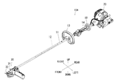
以下、本発明の作業機の一実施形態である刈払機を添付図面を参照して説明する。図1に示したように、刈払機10は、前後方向に延びる細長い円筒形をした操作棹11と、操作棹11の後端部にエンジン(原動機)20と、操作棹11の前端部に設けられてエンジン20により回転する回転刃(回転工具)32を有したカッタユニット30とを備えている。また、操作棹11内にはエンジン20の駆動を回転刃32に伝達する動力伝達軸12が軸受部材を介して回転可能に支持されている。操作棹11の前後方向の中間部にはループ形をしたループハンドル(把持部)13と、ループハンドル13の後側にグリップハンドル(把持部)14とが設けられている。
Hereinafter, a brush cutter as an embodiment of the working machine of the present invention will be described with reference to the accompanying drawings. As shown in FIG. 1, the brush cutter 10 is provided with a long and narrow cylindrical operation rod 11 extending in the front-rear direction, an engine (prime mover) 20 at the rear end portion of the operation rod 11, and a front end portion of the operation rod 11. And a cutter unit 30 having a rotary blade (rotary tool) 32 that is rotated by the engine 20. Further, a power transmission shaft 12 that transmits the drive of the engine 20 to the rotary blade 32 is rotatably supported in the operation rod 11 via a bearing member. A loop handle (gripping part) 13 having a loop shape is provided in the middle part in the front-rear direction of the operation rod 11, and a grip handle (gripping part) 14 is provided on the rear side of the loop handle 13.
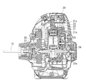
図2に示したように、エンジン20は下部にクランクケース21aと上部にシリンダ21bとを一体的に設けたシリンダブロック21を備え、シリンダブロック21内にはピストン22が上下方向に往復動可能に収容されている。ピストン22の上面とシリンダブロック21の上端部のシリンダヘッド21cとの間が燃焼室23となっている。シリンダヘッド21cには気化器で生成した混合気を燃焼室23に導く吸気ポートと、燃焼室23で発生した排気ガスを排気マフラに導く排気ポートが設けられている(何れも図示省略)。
As shown in FIG. 2, the engine 20 includes a cylinder block 21 in which a crankcase 21a and a cylinder 21b are integrally provided at a lower portion, and a piston 22 can reciprocate in the vertical direction in the cylinder block 21. Contained. A combustion chamber 23 is formed between the upper surface of the piston 22 and the cylinder head 21 c at the upper end of the cylinder block 21. The cylinder head 21c is provided with an intake port that guides the air-fuel mixture generated by the carburetor to the combustion chamber 23 and an exhaust port that guides the exhaust gas generated in the combustion chamber 23 to the exhaust muffler (both not shown).
クランクケース21aにはクランクシャフト24が設けられており、クランクシャフト24は前後方向を軸線方向とした軸線回りに回転可能に支持されている。クランクシャフト24にはコネクティングロッド25を介してピストン22が連結されており、ピストン22の上下方向の往復運動がクランクシャフト24の回転運動に変換される。クランクシャフト24の前端部にはフライホイール26が設けられており、フライホイール26はクランクシャフト24の回転を安定させるとともにエンジン20内を冷却する機能を有している。クランクシャフト24の前端部にはフライホイール26より前側に遠心クラッチ27が設けられており、遠心クラッチ27はクランクシャフト24の回転数が所定値以上となるとクランクシャフト24の回転を操作棹11内の動力伝達軸12に伝達する。
A crankshaft 24 is provided in the crankcase 21a, and the crankshaft 24 is supported so as to be rotatable about an axis whose front-rear direction is an axial direction. A piston 22 is connected to the crankshaft 24 via a connecting rod 25, and the reciprocating motion of the piston 22 in the vertical direction is converted into the rotational motion of the crankshaft 24. A flywheel 26 is provided at the front end of the crankshaft 24, and the flywheel 26 has a function of stabilizing the rotation of the crankshaft 24 and cooling the inside of the engine 20. A centrifugal clutch 27 is provided at the front end of the crankshaft 24 on the front side of the flywheel 26. The centrifugal clutch 27 allows the crankshaft 24 to rotate when the rotational speed of the crankshaft 24 exceeds a predetermined value. It is transmitted to the power transmission shaft 12.
図1に示したように、カッタユニット30は操作棹11の前端部に固定された前端ハウジング31を備えており、前端ハウジング31には回転軸(図示省略)が回転可能に支持されている。回転軸の基端部にはベベルギヤ(図示省略)が固定されており、このベベルギヤには動力伝達軸12の前端部に固定したベベルギヤが係合して、動力伝達軸12の回転がこれらベベルギヤを介して回転軸に伝達される。回転軸の先端は前端ハウジング31の下側に突出しており、回転軸の先端には回転刃32が取り付けられている。この実施形態の回転刃32はナイロンコードを用いたものであるが、外周部に刃部を形成した円板状の回転刃を用いたものであってもよい。
As shown in FIG. 1, the cutter unit 30 includes a front end housing 31 fixed to the front end portion of the operation rod 11, and a rotating shaft (not shown) is rotatably supported by the front end housing 31. A bevel gear (not shown) is fixed to the base end portion of the rotation shaft, and the bevel gear fixed to the front end portion of the power transmission shaft 12 is engaged with the bevel gear, and the rotation of the power transmission shaft 12 causes the bevel gear to rotate. Is transmitted to the rotating shaft. The tip of the rotating shaft protrudes below the front end housing 31, and a rotary blade 32 is attached to the tip of the rotating shaft. Although the rotary blade 32 of this embodiment uses a nylon cord, it may use a disk-shaped rotary blade having a blade portion on the outer peripheral portion.
図1及び図3に示したように、操作棹11の後端部にはマウントフレーム40が固定されており、マウントフレーム40にはエンジン20が防振的に搭載されている。マウントフレーム40は、操作棹11の後端部に固定されて上下に延びる起立部41と、起立部41の下端から後方に延出する台座部42とを有している。マウントフレーム40には起立部41の後面とエンジン20の前部との間に左右一対の第1圧縮ばね(弾性部材)43が設けられ、台座部42の上面後部とエンジン20の後側下部との間に左右一対の第2圧縮ばね(弾性部材)44が設けられている。第1圧縮ばね43は前後方向に延び、前後方向に伸縮自在かつ前後方向と交差する方向(上下方向及び左右方向)に揺動自在にエンジン20を支持している。第2圧縮ばね44は上下方向に延び、上下方向に伸縮自在かつ上下方向と交差する方向(前後方向及び左右方向)に揺動自在にエンジン20を支持している。
1 and 3, the mount frame 40 is fixed to the rear end of the operation rod 11, and the engine 20 is mounted on the mount frame 40 in a vibration-proof manner. The mount frame 40 includes an upright portion 41 that is fixed to the rear end portion of the operation rod 11 and extends up and down, and a pedestal portion 42 that extends rearward from the lower end of the upright portion 41. The mount frame 40 is provided with a pair of left and right first compression springs (elastic members) 43 between the rear surface of the upright portion 41 and the front portion of the engine 20, and the upper surface rear portion of the pedestal portion 42 and the rear lower portion of the engine 20. A pair of left and right second compression springs (elastic members) 44 are provided between them. The first compression spring 43 extends in the front-rear direction, and supports the engine 20 so that it can expand and contract in the front-rear direction and swing in directions crossing the front-rear direction (vertical direction and left-right direction). The second compression spring 44 extends in the vertical direction, and supports the engine 20 so that it can expand and contract in the vertical direction and swing in directions intersecting the vertical direction (front-rear direction and left-right direction).
上記のように構成した刈払機10においては、エンジン20を駆動させると、上下方向に往復動するピストン22によりクランクシャフト24が回転し、クランクシャフト24が遠心クラッチ27により動力伝達軸12に連結されて動力伝達軸12を回転させ、動力伝達軸12の回転が前端ハウジング31内にて一対のベベルギヤを介して回転軸に伝達され、回転軸に固定した回転刃32が回転する。作業者は一方の手でループハンドル13と、他方の手でグリップハンドル14とを把持し、これらハンドル13,14を操作して回転刃32を地面の上側に沿って左右に揺動させることで、地面から生える草、芝等が刈り取られる。
In the brush cutter 10 configured as described above, when the engine 20 is driven, the crankshaft 24 is rotated by the piston 22 reciprocating in the vertical direction, and the crankshaft 24 is connected to the power transmission shaft 12 by the centrifugal clutch 27. Then, the power transmission shaft 12 is rotated, and the rotation of the power transmission shaft 12 is transmitted to the rotation shaft through the pair of bevel gears in the front end housing 31, and the rotary blade 32 fixed to the rotation shaft rotates. The operator holds the loop handle 13 with one hand and the grip handle 14 with the other hand, and operates the handles 13 and 14 to swing the rotary blade 32 left and right along the upper side of the ground. Grass, grass, etc. growing from the ground are cut off.
エンジン20を駆動させているときには、ピストン22がシリンダブロック21のシリンダ21b内を上下方向に往復動することで、エンジン20が上下方向に振動するとともに、クランクシャフト24がクランクケース21a内で回転することにより、エンジン20が前後方向の軸線回りに振動する。
When the engine 20 is driven, the piston 22 reciprocates in the cylinder 21b of the cylinder block 21 in the vertical direction, so that the engine 20 vibrates in the vertical direction and the crankshaft 24 rotates in the crankcase 21a. As a result, the engine 20 vibrates around the axis in the front-rear direction.
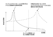
この実施形態の刈払機10は、操作棹11の後端部にエンジン20を搭載するマウントフレーム40を一体的に固定し、マウントフレーム40にエンジン20を防振的に支持する第1及び第2圧縮ばね43,44を設けた。具体的には、マウントフレーム40は操作棹11の後端部に固定されて上下に延びる起立部41と、起立部41の下端から後方に延出する台座部42とを有し、起立部41の後面とエンジン20の前部との間に左右一対の第1圧縮ばね43を設け、台座部42の上面後部とエンジン20の後側下部との間に左右一対の第2圧縮ばね44を設けた。第1圧縮ばね43は前後方向に伸縮自在かつ前後方向と交差する方向(上下方向及び左右方向)に揺動自在にエンジン20を支持し、第2圧縮ばね44は上下方向に伸縮自在かつ上下方向と交差する方向(前後方向及び左右方向)に揺動自在にエンジン20を支持している。図4に示したように、エンジン20を第1及び第2圧縮ばね43,44により防振的にマウントフレーム40に搭載したことで、エンジン20とマウントフレーム40とこの両者を連結する第1及び第2圧縮ばね43,44とからなる振動系の固有周波数をエンジン20の振動から生じる周波数から大幅に離すことができ、エンジン20の駆動によって生じる起振力が伝達することを減少させることができた。これにより、エンジン20の振動は第1及び第2圧縮ばね43,44によってマウントフレーム40を固定した操作棹11に伝達されにくくなり、作業者が操作棹11に設けた各ハンドル13,14を把持しても振動によって疲労しにくくなった。なお、操作棹11内の動力伝達軸12はエンジン20の駆動により回転し、動力伝達軸12の回転による振動が操作棹11に伝わるおそれがあるが、操作棹11内に動力伝達軸12を覆う細長いチューブ(管部材)を介装し、チューブをゴム等の柔軟弾性部材を介して操作棹11内に介装すれば、動力伝達軸12の振動が操作棹11に伝達するのを抑制できる。また、動力伝達軸12は長尺の棒状の軸部材に限られるものでなく、フレキシブルシャフト等の可撓性をした長尺の軸部材を用いたものであってもよく、特に、可撓性をした長尺の軸部材を用いたときには動力伝達軸12の回転により振動が生じるおそれがあるが、チューブの外側に介装した柔軟弾性部材により振動を抑制することができる。
In the brush cutter 10 of this embodiment, the mount frame 40 on which the engine 20 is mounted is fixed integrally to the rear end portion of the operation rod 11, and the first and second are supported on the mount frame 40 in a vibration-proof manner. Compression springs 43 and 44 are provided. Specifically, the mount frame 40 includes an upright portion 41 that is fixed to the rear end portion of the operating rod 11 and extends up and down, and a pedestal portion 42 that extends rearward from the lower end of the upright portion 41. A pair of left and right first compression springs 43 are provided between the rear surface and the front portion of the engine 20, and a pair of left and right second compression springs 44 are provided between the upper surface rear portion of the pedestal portion 42 and the rear lower portion of the engine 20. It was. The first compression spring 43 supports the engine 20 such that it can expand and contract in the front-rear direction and swing in the direction intersecting with the front-rear direction (vertical direction and left-right direction), and the second compression spring 44 can be expanded and contracted in the vertical direction The engine 20 is supported so as to be swingable in the direction intersecting with (the front-rear direction and the left-right direction). As shown in FIG. 4, since the engine 20 is mounted on the mount frame 40 in a vibration-proof manner by the first and second compression springs 43 and 44, the engine 20 and the mount frame 40 are connected to each other. The natural frequency of the vibration system composed of the second compression springs 43 and 44 can be greatly separated from the frequency generated from the vibration of the engine 20, and transmission of the vibration generated by the drive of the engine 20 can be reduced. It was. As a result, the vibration of the engine 20 is not easily transmitted to the operating rod 11 with the mount frame 40 fixed by the first and second compression springs 43 and 44, and the operator holds the handles 13 and 14 provided on the operating rod 11. Even so, it became hard to get tired by vibration. The power transmission shaft 12 in the operation rod 11 rotates by driving the engine 20, and vibration due to the rotation of the power transmission shaft 12 may be transmitted to the operation rod 11, but the power transmission shaft 12 is covered in the operation rod 11. If an elongated tube (pipe member) is interposed and the tube is interposed in the operation rod 11 via a flexible elastic member such as rubber, it is possible to suppress the vibration of the power transmission shaft 12 from being transmitted to the operation rod 11. Further, the power transmission shaft 12 is not limited to a long rod-shaped shaft member, and may be one using a flexible long shaft member such as a flexible shaft. When a long shaft member is used, vibration may occur due to rotation of the power transmission shaft 12, but vibration can be suppressed by a flexible elastic member interposed outside the tube.
また、エンジン20等の振動を各ハンドル13,14に伝達しにくくする方法として、操作棹11と各ハンドル13,14との間にゴム等の柔軟弾性部材を介装して、エンジン20等の振動が操作棹11から各ハンドル13,14に伝達するのを抑制することも可能である。しかし、この場合には、各ハンドル13,14が操作棹11との間に介装した柔軟弾性部材によって揺れ動く可能性があり、各ハンドル13,14の操作性が低下するおそれがある。これに対し、本発明のように、操作棹11の後端に固定したマウントフレーム40に第1及び第2圧縮ばね43,44を介してエンジン20を搭載したものであれば、各ハンドル13,14と操作棹11との間にゴム等の柔軟弾性部材を介装する必要がないので、各ハンドル13,14を安定した状態で操作棹11に固定することができ、各ハンドル13,14に伝わる振動を低減させることと、各ハンドル13,14の操作性を維持することの両立をすることができた。
Further, as a method for making it difficult to transmit the vibration of the engine 20 or the like to the handles 13 and 14, a flexible elastic member such as rubber is interposed between the operation rod 11 and the handles 13 and 14. It is also possible to suppress vibration from being transmitted from the operation rod 11 to the handles 13 and 14. However, in this case, the handles 13 and 14 may be swayed by the flexible elastic member interposed between the operation rod 11 and the operability of the handles 13 and 14 may be reduced. On the other hand, if the engine 20 is mounted on the mount frame 40 fixed to the rear end of the operation rod 11 via the first and second compression springs 43 and 44 as in the present invention, each handle 13, Since it is not necessary to interpose a flexible elastic member such as rubber between the operation lever 11 and the operation rod 11, the handles 13 and 14 can be fixed to the operation rod 11 in a stable state. It was possible to reduce both the transmitted vibration and maintain the operability of the handles 13 and 14.
上記の実施形態では、弾性部材として圧縮ばね43,44を採用したが、本発明はこれに限られるものでなく、他の弾性部材として板ばね、筒形状または柱形状をしたゴム等の柔軟弾性体または空気ばね等を採用してもよく、このようにしたときにも、上述したのと同様の作用効果を得ることができる。
In the above embodiment, the compression springs 43 and 44 are employed as the elastic members. However, the present invention is not limited to this, and the other elastic members may be a flexible spring such as a leaf spring, a cylindrical or columnar rubber, or the like. A body, an air spring, or the like may be employed, and even when this is done, the same effects as described above can be obtained.
上記の実施形態では、操作棹11は真直な円筒形をした管部材を用いたが、本発明はこれに限られるものでなく、先端部が湾曲したベント形の管部材を用いものであってもよく、このようにしたときにも同様の作用効果を得ることができる。
In the above embodiment, the operation rod 11 uses a straight cylindrical tube member, but the present invention is not limited to this, and uses a bent tube member having a curved tip. In this way, the same effect can be obtained.
上記の実施形態では、把持部としてループハンドル13とグリップハンドル14とを採用した刈払機について説明したが、本発明はこれに限られるものでなく、ループハンドル13とグリップハンドル14との一方のみを採用した刈払機、ループハンドル13とグリップハンドル14に代えてU字形をしたU字形ハンドルを採用した刈払機であっても同様の作用効果を得ることができる。
In the above embodiment, the brush cutter using the loop handle 13 and the grip handle 14 as the grip portion has been described. However, the present invention is not limited to this, and only one of the loop handle 13 and the grip handle 14 is used. The same effect can be obtained even with a brush cutter that employs a U-shaped handle instead of the employed brush cutter or the loop handle 13 and the grip handle 14.
上記の実施形態では、回転工具として回転刃を用いた刈払機について説明したが、本発明の作業機はこれに限られるものでなく、回転工具として研磨器を用いたポリッシャー、グラインダー等の研磨機等にも適用できるものである。
In the above embodiment, a brush cutter using a rotary blade as a rotary tool has been described. However, the working machine of the present invention is not limited to this, and a polisher such as a polisher or a grinder using a polisher as a rotary tool. It can be applied to the above.
図5~図7においては、本発明による作業機の他の実施形態が示されている。この実施形態においては、上述した第1実施形態における原動機20と実質的に同じ原動機20を操作棹11の後端部に直接組み付けて、後述する動吸振器50を原動機20とグリップハンドル(把持部)14の間にて操作棹11に組み付けたことに特徴があり、その他の構成要素は第1実施形態と同じであるので、同一部材と同一部分には同一の符号を付してその説明は省略する。
5 to 7 show other embodiments of the working machine according to the present invention. In this embodiment, the prime mover 20 substantially the same as the prime mover 20 in the first embodiment described above is directly assembled to the rear end portion of the operating rod 11, and the dynamic vibration absorber 50 described later is connected to the prime mover 20 and the grip handle (gripping part). ), And the other components are the same as those in the first embodiment. Therefore, the same members and the same parts are denoted by the same reference numerals, and the description thereof is as follows. Omitted.
しかして、この第2実施形態は、作業者が把持する把持部13,14を有した操作棹11と、同操作棹11の後端部に設けた原動機20と、操作棹11の前端部に設けられて原動機により回転する回転工具32と、操作棹11内に回転可能に支持されて原動機20の駆動を回転工具32に伝達する動力伝達軸12とを備えた作業機において、 操作棹11の外周部に固定した支持体51と、同支持体51の外側にて離間して配置した質量体52と、同質量体52を支持体51に対して揺動自在に支持する弾性体55とを有した動吸振器50を備えたことを特徴とする作業機10Aを提供するものである。
Thus, in the second embodiment, the operating rod 11 having the grip portions 13 and 14 that the operator grips, the prime mover 20 provided at the rear end portion of the operating rod 11, and the front end portion of the operating rod 11 In a working machine provided with a rotary tool 32 that is provided and rotated by a prime mover, and a power transmission shaft 12 that is rotatably supported in the operation rod 11 and transmits the drive of the prime mover 20 to the rotary tool 32, A support body 51 fixed to the outer periphery, a mass body 52 spaced apart from the outside of the support body 51, and an elastic body 55 that supports the mass body 52 so as to be swingable with respect to the support body 51. The working machine 10A is provided with the dynamic vibration absorber 50 provided.
図5び図7に示したように、操作棹11には動吸振器50が設けられており、動吸振器50は、主としてエンジン20から操作棹11に伝わる振動を低減させるためのものである。動吸振器50は操作棹11の後部にてグリップハンドル14とエンジン20との間に配置されている。動吸振器50は、操作棹11の後部の外周部に固定した支持体51と、支持体51の外側にて離間して配置した質量体52と、質量体52を支持体51に対して揺動自在に支持する弾性体55とを備えている。支持体51は短い円筒形状をしており、支持体51の周部には半径方向に延びる8つの取付孔51aが周方向にて等間隔に形成されている。これら取付孔51aは弾性体55を取り付けるためのものであり、外周側が大きく内周側が小さな2つの円柱孔を同心的に配置した段付き孔である。
As shown in FIGS. 5 and 7, the operating rod 11 is provided with a dynamic vibration absorber 50, and the dynamic vibration absorber 50 is mainly for reducing vibration transmitted from the engine 20 to the operating rod 11. . The dynamic vibration absorber 50 is disposed between the grip handle 14 and the engine 20 at the rear portion of the operation rod 11. The dynamic vibration absorber 50 includes a support body 51 fixed to the outer peripheral portion of the rear part of the operation rod 11, a mass body 52 that is spaced apart from the support body 51, and a mass body 52 that swings the mass body 52 relative to the support body 51. And an elastic body 55 that is movably supported. The support 51 has a short cylindrical shape, and eight mounting holes 51 a extending in the radial direction are formed at equal intervals in the circumferential direction on the periphery of the support 51. These mounting holes 51a are for mounting the elastic body 55, and are stepped holes in which two cylindrical holes having a large outer peripheral side and a small inner peripheral side are arranged concentrically.
質量体52は支持体51より大きな径をした短い円筒形状をした内側部53と、同内側部53の外周面に嵌合する短い円筒形状をした外側部54とを有し、これら内側部53及び外側部54はともにステンレス等の金属部材を用いた構造物である。質量体52の内側部53には支持体51の取付孔51aと対向する位置に半径方向に延びる8つの貫通孔53aが周方向にて等間隔に形成されており、これら貫通孔53aは弾性体55の中間部から先端までを収容して、弾性体55を質量体52に対して取り付けるためのものである。外側部54は内側部53を外側から覆うように嵌合しており、ねじにより内側部53に固定されている。外側部54には内側部53の貫通孔53aと対向する位置に貫通孔53aより小径の貫通孔54aが設けられており、貫通孔54aの周部により弾性体55を抜け止めするようにしている。
The mass body 52 has a short cylindrical inner portion 53 having a larger diameter than the support 51 and a short cylindrical outer portion 54 fitted to the outer peripheral surface of the inner portion 53. The outer portion 54 is a structure using a metal member such as stainless steel. Eight through holes 53a extending in the radial direction are formed at equal positions in the circumferential direction at positions facing the mounting holes 51a of the support body 51 in the inner portion 53 of the mass body 52, and these through holes 53a are elastic bodies. The elastic body 55 is attached to the mass body 52 by accommodating the middle part to the front end of 55. The outer portion 54 is fitted so as to cover the inner portion 53 from the outside, and is fixed to the inner portion 53 with screws. The outer portion 54 is provided with a through hole 54a having a smaller diameter than the through hole 53a at a position facing the through hole 53a of the inner portion 53, and the elastic body 55 is prevented from being detached by the peripheral portion of the through hole 54a. .
弾性体55は、質量体52を支持体51に同心的に離間させた状態で、質量体52を揺動可能に支持体51に支持するためのものである。弾性体55は、ゴム等の柔軟弾性部材を円柱形状としたものである。弾性体55は、基端を支持体51の取付孔51aの底部によって抜け止めした状態で、基端部が支持体51の取付孔51aに位置決めされて取り付けられ、先端を質量体52の外側部54によって抜け止めした状態で、中間部より先端側が質量体52の内側部53の貫通孔53a内に位置決めされて取り付けられている。質量体52は8つの弾性体55により支持体51に対して並進3自由度及び回転3自由度の6自由度で揺動自在に支持されている。なお、弾性体55はゴム等の柔軟弾性部材に限られるものでなく、コイルスプリング等のばね部材を用いたものであってもよい。また、この実施形態では周方向に等間隔に8つの弾性体55を配置したが、これに限られるものでなく、3つ以上の弾性体55を等間隔に配置したものであってもよい。また、形状も円筒に限られるものでなく、支持体51と質量体52とを全周ゴム等の弾性体で接合(例えば一体成型)したものであってもよい。
The elastic body 55 is for supporting the mass body 52 on the support body 51 so as to be swingable in a state where the mass body 52 is concentrically spaced from the support body 51. The elastic body 55 is made of a flexible elastic member such as rubber having a cylindrical shape. The elastic body 55 is mounted with its base end positioned in the mounting hole 51a of the support 51 in a state where the base end is secured by the bottom of the mounting hole 51a of the support 51, and the tip is attached to the outer portion of the mass body 52. In a state where it is prevented from being detached by 54, the tip side from the intermediate part is positioned and attached in the through hole 53 a of the inner part 53 of the mass body 52. The mass body 52 is supported by the eight elastic bodies 55 so as to be swingable with respect to the support body 51 with six degrees of freedom of three translational degrees of freedom and three degrees of freedom of rotation. The elastic body 55 is not limited to a flexible elastic member such as rubber, and may be one using a spring member such as a coil spring. In this embodiment, eight elastic bodies 55 are arranged at equal intervals in the circumferential direction. However, the present invention is not limited to this, and three or more elastic bodies 55 may be arranged at equal intervals. Further, the shape is not limited to a cylinder, and the support body 51 and the mass body 52 may be joined (for example, integrally molded) with an elastic body such as a whole circumference rubber.
上記のように構成した刈払機10Aにおいては、エンジン20を駆動させると、上下方向に往復動するピストン22によりクランクシャフト24が回転し、クランクシャフト24が遠心クラッチ27により動力伝達軸12に連結されて動力伝達軸12を回転させ、動力伝達軸12の回転が一対のベベルギヤを介して回転軸に伝達され、回転軸に固定した回転刃32が回転する。作業者は一方の手でループハンドル13と、他方の手でグリップハンドル14とを把持し、これらハンドル13,14を操作して回転刃32を地面の上側に沿って左右に揺動させることで、地面から生える草、芝等が刈り取られる。
In the brush cutter 10A configured as described above, when the engine 20 is driven, the crankshaft 24 is rotated by the piston 22 reciprocating in the vertical direction, and the crankshaft 24 is connected to the power transmission shaft 12 by the centrifugal clutch 27. Then, the power transmission shaft 12 is rotated, and the rotation of the power transmission shaft 12 is transmitted to the rotation shaft through the pair of bevel gears, and the rotary blade 32 fixed to the rotation shaft rotates. The operator holds the loop handle 13 with one hand and the grip handle 14 with the other hand, and operates the handles 13 and 14 to swing the rotary blade 32 left and right along the upper side of the ground. Grass, grass, etc. growing from the ground are cut off.
エンジン20を駆動させているときには、ピストン22がシリンダブロック21のシリンダ21b内を上下方向に往復動することで、エンジン20が上下方向に振動するとともに、クランクシャフト24がクランクケース21a内で回転することにより、エンジン20が前後方向の軸線回りに振動し、エンジン20のこれらの振動が操作棹11に伝わることになる。また、エンジン20の駆動により回転する動力伝達軸12の回転による振動が軸受部材を介して操作棹11にも伝わっている。
When the engine 20 is driven, the piston 22 reciprocates in the cylinder 21b of the cylinder block 21 in the vertical direction, so that the engine 20 vibrates in the vertical direction and the crankshaft 24 rotates in the crankcase 21a. As a result, the engine 20 vibrates around the axis in the front-rear direction, and these vibrations of the engine 20 are transmitted to the operation rod 11. Further, vibration due to the rotation of the power transmission shaft 12 that is rotated by driving the engine 20 is also transmitted to the operation rod 11 through the bearing member.
この実施形態の刈払機10Aは、操作棹11の外周部に固定した支持体51と、支持体51の外側にて離間して配置した質量体52と、質量体を支持体51に対して揺動自在に支持する弾性体55とを有した動吸振器50を備えている。動吸振器50は質量体52がエンジン20の駆動及び動力伝達軸12の回転による振動を低減させるように揺動することによって、操作棹11に伝達された振動を低減させ、操作棹11に設けたループハンドル13と、グリップハンドル14の振動も抑制される。ループハンドル13とグリップハンドル14の振動をIEC60335-2-91に準拠して3軸加速度を計測した結果、ループハンドル13に生じた振動は動吸振器を設けてないものと比べて上下方向の振動を約10%に抑制することができた。また、グリップハンドル14に生じた振動は動吸振器を設けてないものと比べて左右方向の振動を約8%に、前後方向の振動を約9%に、上下方向の振動を約14%に大きく抑制することができた。これにより、作業者がループハンドル13と、グリップハンドル14を把持してもエンジン20等で発生した振動によって疲れにくくなった。
The brush cutter 10 </ b> A according to this embodiment includes a support body 51 fixed to the outer periphery of the operation rod 11, a mass body 52 that is spaced apart from the outside of the support body 51, and a mass body that rocks the support body 51. A dynamic vibration absorber 50 having an elastic body 55 that is movably supported is provided. The dynamic vibration absorber 50 is provided on the operation rod 11 by reducing the vibration transmitted to the operation rod 11 by swinging the mass body 52 so as to reduce the vibration caused by the driving of the engine 20 and the rotation of the power transmission shaft 12. The vibration of the loop handle 13 and the grip handle 14 is also suppressed. As a result of measuring the triaxial acceleration of the vibration of the loop handle 13 and the grip handle 14 in accordance with IEC 60335-2-91, the vibration generated in the loop handle 13 is a vibration in the vertical direction as compared with the case where no dynamic vibration absorber is provided. Was suppressed to about 10%. In addition, the vibration generated in the grip handle 14 is about 8% in the left-right direction, about 9% in the front-rear direction, and about 14% in the up-down direction compared to the case without the dynamic vibration absorber. It was possible to greatly suppress. As a result, even if the operator grips the loop handle 13 and the grip handle 14, it is less likely to get tired due to vibration generated in the engine 20 or the like.
特に、この刈払機10Aにおいては、動吸振器50は質量体52を弾性体55によって並進3自由度かつ回転3自由度の6自由度に揺動自在に支持体51に支持したものである。これにより、エンジン20が上下方向に振動するだけでなく、前後方向を軸線回りに回転する方向に振動するときのように複数の振動に起因して複雑な振動が生じても、質量体52がこれらの振動を低減するように揺動して、作業者がハンドル13,14を把持しても疲れにくくなった。さらに、例えばピストン22を直立した状態から傾いて配置したときのように、エンジン20の配置及び仕様により振動する方向が異なる機種の刈払機にこの動吸振器50を採用したときでも、エンジン20から操作棹11に伝達された振動を抑制することが可能となり、この動吸振器50の汎用性を高くすることができた。
In particular, in the brush cutter 10A, the dynamic vibration absorber 50 is configured such that the mass body 52 is supported by the support body 51 by the elastic body 55 so that the mass body 52 can swing freely in 6 degrees of freedom of translation and 3 degrees of rotation. Thereby, not only the engine 20 vibrates in the vertical direction but also the mass body 52 does not cause the mass body 52 even when complicated vibrations are caused due to a plurality of vibrations such as when the front-rear direction is vibrated in a direction rotating around the axis. Even if the operator grips the handles 13 and 14 by swinging so as to reduce these vibrations, it becomes hard to get tired. Further, even when this dynamic vibration absorber 50 is adopted in a brush cutter of a model in which the direction of vibration differs depending on the arrangement and specifications of the engine 20, for example, when the piston 22 is inclined from an upright state, The vibration transmitted to the operation rod 11 can be suppressed, and the versatility of the dynamic vibration absorber 50 can be increased.
また、この刈払機10Aにおいては、動吸振器50をエンジン20とグリップハンドル14(ループハンドル13も含む)との間に設けた。これにより、動吸振器50はエンジン20から操作棹11に伝わった振動をグリップハンドル14及びループハンドル13に伝達する前に低減させることができ、エンジン20の振動がグリップハンドル14及びループハンドル13にさらに伝わりにくくなった。なお、動吸振器50を操作棹11のエンジン20とグリップハンドル14(ループハンドル13も含む)との間に設けるのが最適であるが、これに限られものでなく、例えば、動吸振器50を操作棹11のループハンドル13とグリップハンドル14の間またはループハンドル13より前側に設けたとしても、エンジン20から操作棹11に伝達された振動を低減させることができる。
Further, in the brush cutter 10A, the dynamic vibration absorber 50 is provided between the engine 20 and the grip handle 14 (including the loop handle 13). As a result, the dynamic vibration absorber 50 can reduce the vibration transmitted from the engine 20 to the operating rod 11 before transmitting it to the grip handle 14 and the loop handle 13, and the vibration of the engine 20 is reduced to the grip handle 14 and the loop handle 13. It became more difficult to communicate. The dynamic vibration absorber 50 is optimally provided between the engine 20 of the operating rod 11 and the grip handle 14 (including the loop handle 13), but is not limited to this. For example, the dynamic vibration absorber 50 is provided. Even if it is provided between the loop handle 13 and the grip handle 14 of the operating rod 11 or in front of the loop handle 13, the vibration transmitted from the engine 20 to the operating rod 11 can be reduced.
また、エンジン20等の振動を各ハンドル13,14に伝達しにくくする方法として、操作棹11と各ハンドル13,14との間にゴム等の柔軟弾性部材を介装して、エンジン20等の振動が操作棹11から各ハンドル13,14に伝達するのを抑制することも可能である。しかし、この場合には、各ハンドル13,14が操作棹11との間に介装した柔軟弾性部材によって揺れ動く可能性があり、各ハンドル13,14の操作性が低下するおそれがある。これに対し、本発明のように、操作棹11に動吸振器50を設けたものであれば、各ハンドル13,14と操作棹11との間にゴム等の柔軟弾性部材を介装する必要がないので、各ハンドル13,14を安定した状態で操作棹11に固定することができ、各ハンドル13,14に伝わる振動を低減させることと、各ハンドル13,14の操作性を維持することの両立をすることができた。
Further, as a method for making it difficult to transmit the vibration of the engine 20 or the like to the handles 13 and 14, a flexible elastic member such as rubber is interposed between the operation rod 11 and the handles 13 and 14. It is also possible to suppress vibration from being transmitted from the operation rod 11 to the handles 13 and 14. However, in this case, the handles 13 and 14 may be swayed by the flexible elastic member interposed between the operation rod 11 and the operability of the handles 13 and 14 may be reduced. On the other hand, if the operation rod 11 is provided with the dynamic vibration absorber 50 as in the present invention, a flexible elastic member such as rubber needs to be interposed between the handles 13 and 14 and the operation rod 11. Therefore, the handles 13 and 14 can be fixed to the operation rod 11 in a stable state, vibrations transmitted to the handles 13 and 14 can be reduced, and the operability of the handles 13 and 14 can be maintained. I was able to balance both.
上記の実施形態では、把持部としてループハンドル13とグリップハンドル14とを採用した刈払機について説明したが、本発明はこれに限られるものでなく、ループハンドル13とグリップハンドル14との一方のみを採用した刈払機、ループハンドル13とグリップハンドル14に代えてU字形をしたU字形ハンドルを採用した刈払機であっても同様の作用効果を得ることができる。
In the above embodiment, the brush cutter using the loop handle 13 and the grip handle 14 as the grip portion has been described. However, the present invention is not limited to this, and only one of the loop handle 13 and the grip handle 14 is used. The same effect can be obtained even with a brush cutter that employs a U-shaped handle instead of the employed brush cutter or the loop handle 13 and the grip handle 14.
10、10A…作業機(刈払機)、11…操作棹、12…動力伝達軸、13…把持部(ループハンドル)、14…把持部(グリップハンドル)、20…原動機(エンジン)、32…回転工具(回転刃)、40…マウントフレーム、41…起立部、42…台座部、43…弾性部材(第1圧縮ばね)、44…弾性部材(第2圧縮ばね)、50・・・動吸振器、51・・・支持体、52・・・質量体、53・・・内側部、54・・・外側部、55・・・弾性体。
DESCRIPTION OF SYMBOLS 10, 10A ... Work machine (brusher), 11 ... Operation rod, 12 ... Power transmission shaft, 13 ... Gripping part (loop handle), 14 ... Gripping part (grip handle), 20 ... Motor (engine), 32 ... Rotation Tool (rotating blade), 40 ... mount frame, 41 ... standing part, 42 ... pedestal part, 43 ... elastic member (first compression spring), 44 ... elastic member (second compression spring), 50 ... dynamic vibration absorber , 51 ... support, 52 ... mass body, 53 ... inner part, 54 ... outer part, 55 ... elastic body.
Claims (6)
- 作業者が把持する把持部を有した操作棹と、
前記操作棹の後端部に設けた原動機と、
前記操作棹の前端部に設けられて前記原動機により回転する回転工具と、
前記操作棹内に回転可能に支持されて前記原動機の駆動を前記回転工具に伝達する動力伝達軸とを備えた作業機において、
前記操作棹の後端部に前記原動機を搭載するマウントフレームを一体的に固定し、
前記マウントフレームに前記原動機を防振的に支持する弾性部材を設けたことを特徴とする作業機。 An operating rod having a gripping part to be gripped by an operator;
A prime mover provided at the rear end of the operating rod;
A rotary tool provided at the front end of the operating rod and rotated by the prime mover;
In a working machine comprising a power transmission shaft that is rotatably supported in the operation rod and transmits the drive of the prime mover to the rotary tool,
A mounting frame for mounting the prime mover is integrally fixed to a rear end portion of the operation rod,
A working machine, wherein the mount frame is provided with an elastic member for supporting the prime mover in a vibration-proof manner. - 請求項1に記載の作業機において、
前記マウントフレームは前記操作棹の後端部に固定されて上下に延びる起立部と、該起立部の下端から後方に延出する台座部とを有し、
前記弾性部材を前記起立部後面と前記原動機の前部との間と、前記台座部上面と前記原動機の下部との間に設けたことを特徴とする作業機。 The working machine according to claim 1,
The mount frame has an upright portion that is fixed to a rear end portion of the operation rod and extends up and down, and a pedestal portion that extends backward from a lower end of the upright portion,
A working machine characterized in that the elastic member is provided between the rear surface of the standing part and the front part of the prime mover, and between the top surface of the pedestal part and the lower part of the prime mover. - 請求項2に記載の作業機において、
前記起立部後面と前記原動機の前部との間に設けた前記弾性部材は前後方向に延びる圧縮ばねを採用し、前記台座部上面と前記原動機の下部との間に設けた前記弾性部材は上下方向に延びる圧縮ばねを採用したことを特徴とする作業機。 The work machine according to claim 2,
The elastic member provided between the rear surface of the upright part and the front part of the prime mover employs a compression spring extending in the front-rear direction, and the elastic member provided between the upper surface of the pedestal part and the lower part of the prime mover A working machine characterized by adopting a compression spring extending in the direction. - 作業者が把持する把持部を有した操作棹と、
前記操作棹の後端部に設けた原動機と、
前記操作棹の前端部に設けられて前記原動機により回転する回転工具と、
前記操作棹内に回転可能に支持されて前記原動機の駆動を前記回転工具に伝達する動力伝達軸とを備えた作業機において、
前記操作棹の外周部に固定した支持体と、前記支持体の外側にて離間して配置した質量体と、前記質量体を前記支持体に対して揺動自在に支持する弾性体とを有した動吸振器を備えたことを特徴とする作業機。 An operating rod having a gripping part to be gripped by an operator;
A prime mover provided at the rear end of the operating rod;
A rotary tool provided at the front end of the operating rod and rotated by the prime mover;
In a working machine comprising a power transmission shaft that is rotatably supported in the operation rod and transmits the drive of the prime mover to the rotary tool,
A support body fixed to the outer periphery of the operation rod; a mass body spaced apart from the support body; and an elastic body that swingably supports the mass body with respect to the support body. A working machine comprising the dynamic vibration absorber. - 請求項4に記載の作業機において、
前記弾性体は前記質量体を前記支持体に対して並進3自由度かつ回転3自由度に揺動自在に支持したことを特徴とする作業機。 The work machine according to claim 4,
The working machine characterized in that the elastic body supports the mass body so as to be swingable with respect to the support body in three degrees of translation and three degrees of rotation. - 請求項4または5に記載の作業機において、
前記動吸振器を前記原動機と前記把持部との間に設けたことを特徴とする作業機。
The working machine according to claim 4 or 5,
A working machine, wherein the dynamic vibration absorber is provided between the prime mover and the grip portion.
Applications Claiming Priority (4)
| Application Number | Priority Date | Filing Date | Title |
|---|---|---|---|
| JP2014-004426 | 2014-01-14 | ||
| JP2014-004417 | 2014-01-14 | ||
| JP2014004426A JP6081384B2 (en) | 2014-01-14 | 2014-01-14 | Working machine |
| JP2014004417A JP2015130831A (en) | 2014-01-14 | 2014-01-14 | Work machine |
Publications (1)
| Publication Number | Publication Date |
|---|---|
| WO2015107731A1 true WO2015107731A1 (en) | 2015-07-23 |
Family
ID=53542642
Family Applications (1)
| Application Number | Title | Priority Date | Filing Date |
|---|---|---|---|
| PCT/JP2014/076944 WO2015107731A1 (en) | 2014-01-14 | 2014-10-08 | Work machine |
Country Status (1)
| Country | Link |
|---|---|
| WO (1) | WO2015107731A1 (en) |
Cited By (1)
| Publication number | Priority date | Publication date | Assignee | Title |
|---|---|---|---|---|
| US11202798B2 (en) | 2010-07-22 | 2021-12-21 | Reven Pharmaceuticals, Inc. | Method of treating or ameliorating skin conditions with a magnetic dipole stabilized solution |
Citations (5)
| Publication number | Priority date | Publication date | Assignee | Title |
|---|---|---|---|---|
| JPS4881015U (en) * | 1972-01-17 | 1973-10-03 | ||
| JPS4925058Y1 (en) * | 1970-04-15 | 1974-07-05 | ||
| JPS533228U (en) * | 1976-06-26 | 1978-01-12 | ||
| JPS5610845A (en) * | 1979-07-09 | 1981-02-03 | Uchiumi Fujio | Handle apparatus |
| JPS5625848U (en) * | 1979-08-03 | 1981-03-10 |
-
2014
- 2014-10-08 WO PCT/JP2014/076944 patent/WO2015107731A1/en active Application Filing
Patent Citations (5)
| Publication number | Priority date | Publication date | Assignee | Title |
|---|---|---|---|---|
| JPS4925058Y1 (en) * | 1970-04-15 | 1974-07-05 | ||
| JPS4881015U (en) * | 1972-01-17 | 1973-10-03 | ||
| JPS533228U (en) * | 1976-06-26 | 1978-01-12 | ||
| JPS5610845A (en) * | 1979-07-09 | 1981-02-03 | Uchiumi Fujio | Handle apparatus |
| JPS5625848U (en) * | 1979-08-03 | 1981-03-10 |
Cited By (1)
| Publication number | Priority date | Publication date | Assignee | Title |
|---|---|---|---|---|
| US11202798B2 (en) | 2010-07-22 | 2021-12-21 | Reven Pharmaceuticals, Inc. | Method of treating or ameliorating skin conditions with a magnetic dipole stabilized solution |
Similar Documents
| Publication | Publication Date | Title |
|---|---|---|
| US9148997B2 (en) | Work apparatus | |
| JP6681226B2 (en) | Chainsaw | |
| CN1846473B (en) | Manually guided trimmer | |
| JP4537600B2 (en) | Brush cutter operation | |
| JP2013151055A (en) | Striking tool | |
| US20210086276A1 (en) | Power tool | |
| US20050198835A1 (en) | Bush cutting machine | |
| GB2430638A (en) | Vibration damping in rotary power tools | |
| WO2015107731A1 (en) | Work machine | |
| JP5942662B2 (en) | Trimming machine | |
| EP1530890B1 (en) | Portable device with anti-vibration handle for use in agriculture and gardening | |
| JP2011254706A (en) | Portable power tool | |
| JP6081384B2 (en) | Working machine | |
| JP2002253024A (en) | Bush cutter | |
| JP2015130831A (en) | Work machine | |
| JP4807505B2 (en) | Brush cutter | |
| JP2020536558A (en) | Electric vegetation cutter | |
| JP6076165B2 (en) | Vibration isolator for portable work machines | |
| WO2010116781A1 (en) | Handheld power tool | |
| JP2013078268A (en) | Bush cutter | |
| JP4212080B2 (en) | Portable work machine | |
| JP2015202064A (en) | Portable work machine | |
| JP2021112178A (en) | Antivibration device of bush cutter | |
| CN110561358B (en) | Hand-held power tool | |
| JP2006014677A (en) | Variable angle transmission apparatus of operating lever |
Legal Events
| Date | Code | Title | Description |
|---|---|---|---|
| 121 | Ep: the epo has been informed by wipo that ep was designated in this application |
Ref document number: 14878431 Country of ref document: EP Kind code of ref document: A1 |
|
| NENP | Non-entry into the national phase |
Ref country code: DE |
|
| 122 | Ep: pct application non-entry in european phase |
Ref document number: 14878431 Country of ref document: EP Kind code of ref document: A1 |