WO2015107688A1 - ガス状試料の分析装置 - Google Patents
ガス状試料の分析装置 Download PDFInfo
- Publication number
- WO2015107688A1 WO2015107688A1 PCT/JP2014/050925 JP2014050925W WO2015107688A1 WO 2015107688 A1 WO2015107688 A1 WO 2015107688A1 JP 2014050925 W JP2014050925 W JP 2014050925W WO 2015107688 A1 WO2015107688 A1 WO 2015107688A1
- Authority
- WO
- WIPO (PCT)
- Prior art keywords
- sample
- gas
- ion
- unit
- ionization
- Prior art date
Links
Images


Classifications
-
- H—ELECTRICITY
- H01—ELECTRIC ELEMENTS
- H01J—ELECTRIC DISCHARGE TUBES OR DISCHARGE LAMPS
- H01J49/00—Particle spectrometers or separator tubes
- H01J49/02—Details
- H01J49/10—Ion sources; Ion guns
- H01J49/16—Ion sources; Ion guns using surface ionisation, e.g. field-, thermionic- or photo-emission
- H01J49/168—Ion sources; Ion guns using surface ionisation, e.g. field-, thermionic- or photo-emission field ionisation, e.g. corona discharge
Definitions
- the present invention relates to an analyzer for analyzing sample components in a sample gas, and more particularly to an analyzer suitable for analyzing components in a sample gas separated by a gas chromatograph.
- Gas chromatograph (GC) detectors include thermal conductivity detector (TCD), electron capture detector (ECD), flame ionization detector (FID), flame photometric detector (FPD), and flame thermonic.
- TCD thermal conductivity detector
- ECD electron capture detector
- FPD flame ionization detector
- FPD flame photometric detector
- Various types of detectors such as a detector (FTD) are used.
- a dielectric barrier discharge ionization detector using ionization by dielectric barrier discharge plasma has recently been put into practical use (see Patent Document 1, Non-Patent Document 1, etc.).
- a predetermined frequency supplied into the pipe line is applied by applying a low-frequency AC high voltage to the electrodes provided around the quartz glass tube as a dielectric.
- the gas is ionized to form a low temperature non-equilibrium atmospheric pressure plasma.
- the sample component in the sample gas introduced into the pipe is ionized by the action of light emitted from the plasma, excited species, etc., and the ion current generated by this ion is detected to detect the amount of the sample component.
- a detection signal corresponding to is output.
- Such dielectric barrier discharge ionization detectors can detect a wide range of organic compounds and inorganic compounds with high sensitivity, and aldehydes, alcohols, halogens, etc., which are difficult to obtain sufficient sensitivity with a conventionally widely used FID. Is characterized by high-sensitivity quantification.
- the dielectric barrier discharge ionization detector has high detection sensitivity, naturally, as with other gas chromatograph detectors, the qualitative information on the components in the sample gas is obtained in addition to the holding time. It is not possible.
- the sample components are not sufficiently separated by the gas chromatograph, that is, when a plurality of sample components are temporally overlapped and introduced into the detector, accurate quantification cannot be performed.
- the present invention has been made in view of these points.
- the detector utilizes the high detection sensitivity for a wide range of compounds.
- the main object of the present invention is to provide a gas sample analyzer that can perform quantitative analysis and perform qualitative analysis with high accuracy.
- An analyzer for a gaseous sample which has been made to solve the above problems, a) a detector for detecting a sample component in a gaseous sample, the discharge electrode having a surface coated with a dielectric, and the discharge electrode for generating a dielectric barrier discharge to generate plasma from a predetermined gas
- a dielectric barrier discharge having an AC voltage application unit for applying a low-frequency AC voltage to the electrode and an ion current detection unit for detecting an ion current due to a sample component in the gaseous sample ionized by the action of the generated plasma
- An ionization detector b) a mass analyzer for separating and detecting ions according to the mass-to-charge ratio; c) an ion transport unit for introducing a part of ions derived from a sample component generated from a gaseous sample in the dielectric barrier discharge ionization detector into the mass spectrometer; It is characterized by having.
- the gas sample analyzing apparatus typically further includes a gas chromatograph, and a dielectric barrier discharge using a sample gas containing a sample component separated by a column of the gas chromatograph as a gas sample to be analyzed. It can be set as the structure introduced into an ionization detector.
- the ion current detection unit in the detector includes an ion collection electrode, and ions derived from the sample component reach the ion collection electrode and are converted into a current signal. However, a part of the ions derived from the sample component passes through the ion transport unit and has a mass. Introduced into the analysis department.
- the mass analyzer has a mass separator such as a quadrupole mass filter, for example, to separate introduced ions according to the mass-to-charge ratio, and the separated ions are detected using a photomultiplier tube. Detected by the instrument.
- a mass separator such as a quadrupole mass filter, for example, to separate introduced ions according to the mass-to-charge ratio, and the separated ions are detected using a photomultiplier tube. Detected by the instrument.
- the sample component in the sample gas is detected by the mass analyzer in parallel with the sensitive detection of the sample component in the sample gas by the dielectric barrier discharge ionization detector. can do.
- ions to be subjected to mass analysis by the mass analyzer are basically ions generated for detecting sample components in a dielectric barrier discharge ionization detector. . Therefore, in order to secure a certain amount of ions to be provided to the mass analysis unit, a part of the ions collected in the vicinity of the ion collection electrode in the ion current detection unit of the dielectric barrier discharge ionization detector is used as the ion collection electrode. It needs to be transported by the ion transport part without reaching.
- the ion transport section includes an ion transport channel that sends ions on at least a part of the predetermined gas flow, and the ion transport channel.
- the inlet end of the ion current may be provided in the vicinity of the ion collection electrode included in the ion current detector. More preferably, the ion collection electrode is provided at the inlet end edge of the ion transport channel.
- a part of the ions collected in the vicinity of the ion collection electrode due to the action of a direct current electric field or the like easily flows into the ion transport channel by riding on the flow of the predetermined gas flowing into the ion transport channel.
- a part of the ions derived from the sample component generated by the action of plasma in the dielectric barrier discharge ionization detector can be reliably introduced into the mass spectrometer without being used for detection by the detector.
- mass separators and ion detectors in the mass analyzer are arranged in a chamber maintained at a high degree of vacuum by evacuation by a vacuum pump, and a large amount of gas is supplied into the chamber by the ion transport unit. Then, it is difficult to maintain the degree of vacuum in the chamber. Also, an expensive vacuum pump with high evacuation performance is required to maintain a high degree of vacuum in the chamber.
- the ion transport unit in order to reduce the amount of the predetermined gas introduced into the evacuated chamber, includes a gas separation unit for separating the gas and the ions. It may be configured. For example, a sampling cone having a minute opening at the top of a cone-shaped body may be used for the gas separation unit so as to separate the gas and ions in different angular directions.
- Such a gas separation unit may be arranged in either an atmospheric pressure atmosphere or a low vacuum atmosphere having a gas pressure lower than atmospheric pressure, but from the viewpoint of separation performance, a sampling cone having a similar structure is preferable. And a skimmer cone are combined, and the space between the two may be evacuated.
- the path for introducing ions from the dielectric barrier discharge ionization detector, which is an atmospheric pressure atmosphere, into the chamber of the mass analysis unit, which is a high vacuum atmosphere is substantially the same as the configuration of the multistage differential exhaust system. Become.
- the amount of gas flowing into the ion transport channel of the ion transport section is large to some extent, the amount of gas flowing into the chamber can be suppressed and the inside of the chamber can be easily maintained at a high degree of vacuum. . Further, it is not necessary to improve the performance of the vacuum pump that evacuates the chamber.
- ions derived from the sample components generated in the dielectric barrier discharge ionization detector are analyzed in the mass spectrometer.
- the ionization part may be provided.
- This auxiliary ionization part is provided so as to ionize the non-ionized sample component contained in the gas sent by the ion transport part, and the ions generated from the sample component are combined with the ions sent by the ion transport part. It is good to use for mass spectrometry.
- the auxiliary ionization part may be one using various conventionally known ionization methods.
- an ionization unit using an atmospheric pressure ionization method such as an atmospheric pressure chemical ionization (APCI) method or an atmospheric pressure photoionization (APPI) method, or an electron ionization (EI) method or a chemical ionization (CI) method is used.
- An ionization part can be used as an auxiliary ionization part.
- auxiliary ionization unit By using such an auxiliary ionization unit, it is possible to increase the amount of ions derived from the sample components to be subjected to mass spectrometry and improve the sensitivity.
- an auxiliary ionization part based on an ionization method that easily generates fragments such as the EI method, fragment ions derived from sample components that are unlikely to be generated by ionization in a dielectric barrier discharge ionization detector can be mass analyzed together. More information about the sample components can be provided to the user.
- mass spectrometry can be performed on the same compound in parallel with detection of a wide range of compounds with high sensitivity by using a dielectric barrier discharge ionization detector.
- mass-to-charge ratio information such as mass spectrum obtained by mass spectrometry.
- mass-to-charge ratio information such as mass spectrum obtained by mass spectrometry.
- a plurality of compound components can be analyzed based on mass spectra obtained by mass spectrometry, extracted ion chromatograms, etc. The overlap can be recognized and quantitative information about each compound can be provided.
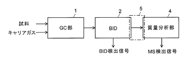
- FIG. 1 is a schematic block configuration diagram of a gas chromatograph mass spectrometer that is one embodiment of the present invention.
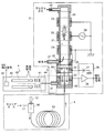
- FIG. The detailed block diagram of the gas chromatograph mass spectrometer of a present Example.
- FIG. 1 is a schematic block diagram of the gas chromatograph mass spectrometer of the present embodiment
- FIG. 2 is a detailed block diagram of the gas chromatograph mass spectrometer of the present embodiment.
- the gas chromatograph mass spectrometer of the present embodiment includes a gas chromatograph (GC) unit 1 that temporally separates various sample components (compounds) contained in a sample, and sample components in the gas separated by the GC unit 1.
- GC gas chromatograph
- a dielectric barrier discharge ionization detector (BID) 2 that detects in time order and a part of ions derived from the sample components generated in the dielectric barrier discharge ionization detector 2 are separated according to the mass-to-charge ratio m / z.
- a mass analyzing unit 4 for detection is described in this embodiment, and analyzes the mass-to-charge ratio.
- an interface unit 5 as an ion transport unit in the present invention between them. Is provided.
- the GC unit 1 includes a capillary column 13, a sample vaporization chamber 10 provided at the inlet end of the capillary column 13, a carrier gas channel 11 connected to the sample vaporization chamber 10, and a sample vaporization A syringe 12 for injecting a small amount of liquid sample into the chamber 10.
- description of a split flow path, a purge flow path, and the like that are generally connected to the sample vaporization chamber 10 is omitted, but it is natural that these can be provided as appropriate.
- the capillary column 13 is housed in a column oven capable of controlling the temperature.
- the dielectric barrier discharge ionization detector 2 has a configuration disclosed in, for example, Non-Patent Document 1 and the like.
- the dielectric barrier discharge ionization detector 2 is provided on the outer wall surface of the dielectric cylindrical tube 20 made of quartz glass or the like in the extending direction of the pipeline.
- An annular discharge electrode 23, 24, 25 made of metal is provided around at a distance. Since there are duct wall surfaces between the discharge electrodes 23, 24, 25 and the first gas flow path 21 inside the dielectric cylindrical tube 20, the wall surfaces themselves that are dielectrics are the discharge electrodes 23, 24, 25. It functions as a dielectric coating layer that covers the surface of the substrate and enables dielectric barrier discharge.
- a plasma gas supply pipe 26 is connected to the upper end of the dielectric cylindrical tube 20, and a plasma gas serving also as a dilution gas is supplied into the first gas flow path 21 through the plasma gas supply pipe 26.
- the central discharge electrode 23 is connected to an excitation high-voltage power supply 28, and the discharge electrodes 24 and 25 arranged above and below the discharge electrode 23 are both grounded.
- the structure in which the discharge electrode 23 to which a high voltage is applied is sandwiched between the two grounded discharge electrodes 24 and 25 prevents the plasma gas generated by the discharge from spreading to the upstream side and the downstream side.
- a typical plasma generation region can be limited between the two discharge electrodes 24, 25.
- the excitation high voltage power supply 28 generates a low frequency high voltage having a frequency in the range of 1 [kHz] to 100 [kHz].
- a recoil electrode 30, a bias electrode 32, and an ion collection electrode 33 are disposed below the dielectric cylindrical tube 20 with an insulator 34 interposed therebetween. These are all cylindrical bodies having the same inner diameter, and a second gas flow path 29 continuous with the first gas flow path 21 is formed inside them, so that the recoil electrode 30, the bias electrode 32, and the ions are formed.
- the collecting electrode 33 is directly exposed to the gas in the second gas flow path 29.
- the recoil electrode 30 located at the connection portion between the first gas flow path 21 and the second gas flow path 29 is grounded, and prevents charged particles in the plasma that may be noise from reaching the ion collection electrode 33.
- the bias electrode 32 is connected to a bias DC power source 37 included in the ion current detection unit 36, and the ion collection electrode 33 is connected to a current amplifier 38 also included in the ion current detection unit 36.
- a bypass exhaust pipe 27 is connected to the end of the first gas passage 21 (and the start end of the second gas passage 29).
- a sample exhaust pipe 31 is connected to the end of the second gas flow path 29 and in the vicinity of the ion collection electrode 34. Furthermore, a small-diameter sample introduction tube 35 connected to the outlet end of the capillary column 13 of the GC unit 1 is inserted into the second gas flow path 29, and the sample component to be measured through the sample introduction tube 35. Is supplied to a position in the second gas passage 29 close to the connection portion of the bypass exhaust pipe 27.
- the mass analyzer 4 includes an ion lens 41, a quadrupole mass filter 42, an ion detector 43, and the like in a chamber 40 that is evacuated by a vacuum pump (not shown), and evacuates the sample of the dielectric barrier discharge ionization detector 2.
- An outlet end of the ion introduction tube 44 connected to the tube 31 is opened in the chamber 40.
- the sample exhaust pipe 31 and the ion introduction pipe 44 correspond to the interface unit 5.
- the sample exhaust pipe 31 and the ion introduction pipe 44 are separated for convenience and are substantially the same continuous pipe line. Note that the temperature of the sample exhaust pipe 31 and the ion introduction pipe 44 may be controlled by a block or the like maintained at an appropriate temperature.
- a substantially constant flow rate of helium (or other inert gas) is supplied as a carrier gas to the sample vaporizing chamber 10 through the carrier gas channel 11.
- helium or other inert gas
- the liquid sample is instantly vaporized and is introduced into the capillary column 13 along with the carrier gas flow.
- Various components in the sample gas are temporally separated while passing through the capillary column 13, flow into the sample introduction pipe 35 from the outlet end of the capillary column 13 with a time difference, and are supplied into the second gas channel 29.
- plasma gas is supplied at a predetermined flow rate into the first gas flow path 21 through the plasma gas supply pipe 26.
- the plasma gas is a gas that is easily ionized and is typically helium, but may be argon, nitrogen, neon, xenon, or a mixed gas thereof.
- the plasma gas flows downward in the first gas flow path 21, passes through the plasma generation region, and a part thereof is discharged to the outside through the bypass exhaust pipe 27.
- the excitation high-voltage power supply 28 is driven in a state where the plasma gas is flowing in the first gas flow path 21, and the excitation high-voltage power supply 28 applies a low-frequency high-voltage AC voltage to one discharge electrode 23.
- the voltage is applied between the other two grounded discharge electrodes 24 and 25.
- dielectric barrier discharge occurs in the plasma generation region sandwiched between the discharge electrodes 24 and 25 in the first gas flow path 21.
- This discharge ionizes the plasma gas flowing in the first gas flow path 21 and generates atmospheric pressure non-equilibrium microplasma.
- the light and excited species emitted from the plasma pass through the first gas channel 21 and the second gas channel 29 to reach the site where the sample gas exists, and ionize the sample components.
- the generated ions gather in the vicinity of the ion collection electrode 33 by a DC electric field formed by a bias DC voltage applied to the bias electrode 32, and exchange ions with the ion collection electrode 33.
- an ionic current corresponding to the amount of the sample component is input to the current amplifier 38, and the current amplifier 38 amplifies it and outputs it as a BID detection signal.
- the dielectric barrier discharge ionization detector 2 outputs a BID detection signal corresponding to the amount (concentration) of the sample component contained in the introduced sample gas.
- ions derived from the sample components generated by the action of the plasma contribute to the ion current, and a part of the ions collected in the vicinity of the ion collecting electrode 33 is directly in the flow of the plasma gas (dilution gas). It rides through the sample exhaust pipe 31 and is transported into the chamber 40 of the mass analyzer 4 through the ion introduction pipe 44. Ions derived from the sample components introduced into the chamber 40 are converged by the action of an electric field by the ion lens 41 and enter the space in the long axis direction of the quadrupole mass filter 42.
- a voltage obtained by superimposing a high-frequency voltage on a DC voltage is applied to four rod electrodes constituting the quadrupole mass filter 42 from a voltage source (not shown), and only ions having a mass-to-charge ratio corresponding to this voltage are quadrupole. It can pass through the mass filter 42.
- the voltage applied to the quadrupole mass filter 42 is repeatedly scanned within a predetermined range. Thereby, since mass scanning over a predetermined mass-to-charge ratio range is executed, the ion detector 43 can repeatedly obtain detection signals corresponding to the mass spectrum.
- the gas chromatograph mass spectrometer of the present embodiment various types of compounds separated by the GC unit 1 are detected with high sensitivity by the dielectric barrier discharge ionization detector 2, and at the same time, by the mass spectrometer 4 By repeatedly obtaining a mass spectrum in a predetermined mass-to-charge ratio range, a mass spectrum in which an ion peak derived from the same compound as that detected by the dielectric barrier discharge ionization detector 2 appears can be obtained every moment. Since the pattern of peaks appearing in this mass spectrum is specific to the compound, for example, the peak pattern of the mass spectrum is compared with the peak pattern of the mass spectrum of a known compound registered in advance in the compound database, and the similarity is examined.
- the compound contained in the sample gas can be identified. Even when multiple compounds are introduced in a time-overlapping manner, for example, a plurality of compounds are separated by peak separation using an extracted ion chromatogram at one or more specific mass-to-charge ratios, and each compound is identified. can do. As a result, qualitative information can be acquired together with highly sensitive quantitative information.
- FIGS. 3 to 6 are all block diagrams of a gas chromatograph mass spectrometer, which is another embodiment of the gaseous sample analyzer according to the present invention.
- the inlet end of the sample exhaust pipe 31 for taking out the ions derived from the sample components from the second gas flow path 29 is provided in the vicinity of the ion collecting electrode 33.
- an ion collection electrode 33 is provided at the inlet end of the sample exhaust pipe 31. Accordingly, compared to the configuration of the embodiment shown in FIG. 2, more ions derived from the sample component approaching the ion collection electrode 33 due to the action of the DC electric field are sent to the sample exhaust pipe 31, and the sample exhaust pipe 31 and the ions It can be transported into the chamber 40 of the mass analyzer 4 through the introduction tube 44.
- the detection sensitivity of the dielectric barrier discharge ionization detector 2 decreases because the amount of ions reaching the ion collection electrode 33 decreases, the amount of ions derived from the sample components used for mass analysis increases.
- the detection sensitivity of the analysis unit 4 is improved.
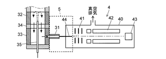
- the configuration of the embodiment shown in FIGS. 4 and 5 includes a gas separation unit that separates ions from the gas as a component of the interface unit 5, and only the ions separated from the gas (actually one of the gases). Part and ions) are introduced into a chamber 40 which is a high vacuum atmosphere and used for mass analysis.
- the outlet end of the sample exhaust pipe 31 is open to the atmospheric pressure atmosphere, and the sampling cone 51 and skimmer are located in front of the gas flow ejected from the outlet end.
- a cone 52 is arranged.
- the sampling cone 51 and the skimmer cone 52 are both conical structures in which orifices 51a and 52a, which are small-diameter openings, are formed at the tops thereof.
- a space 53 between the sampling cone 51 and the skimmer cone 52 is evacuated by a vacuum pump such as a rotary pump, whereby the gas pressure in the space 53 is higher than in the chamber 40 and lower than the atmospheric pressure. It is designed to be kept in a low vacuum atmosphere. That is, the configuration of FIG. 4 is a differential exhaust system configuration in which the degree of vacuum increases stepwise.
- an appropriate DC voltage having the same polarity as the ions to be analyzed is applied to the sampling cone 51 and the skimmer cone 52, respectively.
- the gas flow ejected from the outlet end of the sample exhaust pipe 31 contains ions derived from the sample components, and these ions are centered by the action of the electric field formed by the DC voltage applied to the sampling cone 51 and the skimmer cone 52, respectively. It converges in the vicinity of the shaft and passes through the orifices 51a and 52a in order.
- a part of the gas ejected from the outlet end of the sample exhaust pipe 31 passes through the orifices 51a and 52a, but most of the gas is bent along the tapered portions of the sampling cone 51 and the skimmer cone 52, and the ions And is separated. Thereby, only ions and a small amount of gas can be introduced into the chamber 40 and subjected to mass spectrometry.
- the orifice 51a of the sampling cone 51, the skimmer cone, and the orifice 52a of the 52 may be shifted in parallel, and ions may be guided by an ion lens or the like.
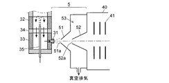
- the gas flow and ions derived from the sample components are directly introduced into the space 53 that is a low vacuum atmosphere through the sample exhaust pipe 31. Only the skimmer cone 52 separates ions from the gas.
- separates ion from gas can be changed suitably.
- the sample component-derived ions generated in the dielectric barrier discharge ionization detector 2 are subjected to mass spectrometry.
- another ionization unit is provided as an auxiliary, and this auxiliary ionization unit is provided.
- the ions derived from the sample components generated in step 1 may also be subjected to mass spectrometry.
- FIG. 6 shows a configuration of an embodiment in which an ionization unit by the EI method is provided as an auxiliary ionization unit.
- the gas flow that has passed through the sample exhaust pipe 31 (or the ion introduction pipe 44 in FIGS. 2 and 3) is introduced into the ionization chamber 451 of the auxiliary ionization unit 45, and filaments are introduced into the sample component molecules introduced together with the gas flow. Electrons generated in 452 and accelerated toward the trap electrode 453 are brought into contact with each other. As a result, sample molecules that have not been ionized in the dielectric barrier discharge ionization detector 2 are ionized by the auxiliary ionization unit 45 and are subjected to mass analysis together with ions derived from the sample components that are introduced by riding on the gas flow.
- fragment ions derived from the sample component are easily generated in the auxiliary ionization unit 45, fragment ions derived from the sample component that are difficult to be generated by ionization in the dielectric barrier discharge ionization detector 2 can also be subjected to mass spectrometry. .
- the auxiliary ionization part is not limited to the one based on the EI method, but may be an ionization part based on an ionization method such as the CI method. Moreover, you may use the ion source by atmospheric pressure ionization methods, such as APCI and APPI, as an auxiliary ionization part. Of course, the configuration using such an auxiliary ionization unit and the configuration using the gas separation unit as shown in FIGS. 4 and 5 can be combined.
- ions are separated from the gas flow, and sample component molecules contained in the gas flow are ionized by the auxiliary ionization unit, preventing a decrease in the degree of vacuum in the chamber 40 due to the inflow of gas, and in the mass analysis unit 4 High detection sensitivity can be achieved.
- Quadrupole mass filter 43 ... Ion detector 44 ... Ion introducing tube 45 ... Auxiliary ionization Section 451 ... Ionization chamber 452 ... Filament 453 ... Trap electrode 51 ... Sampling cone 52 ... Skimmer cone 51a, 52a ... Orif Scan 53 ... space
Landscapes
- Physics & Mathematics (AREA)
- Engineering & Computer Science (AREA)
- Plasma & Fusion (AREA)
- Chemical & Material Sciences (AREA)
- Analytical Chemistry (AREA)
- Other Investigation Or Analysis Of Materials By Electrical Means (AREA)
- Electron Tubes For Measurement (AREA)
Abstract
誘電体バリア放電イオン化検出器(2)では、プラズマガスが電離されて形成されたプラズマから発する光等の作用により、試料導入管(35)を通して導入される試料ガス中の試料成分をイオン化し、イオン収集電極(33)により収集して高感度で検出する。イオン収集電極(33)近傍に集まったイオンの一部はガス流に乗って試料排気管(31)から管外に排出され、イオン導入管(44)を通して質量分析部(4)のチャンバ(40)内に送られる。質量分析部(4)は導入された試料成分由来のイオンを質量電荷比に応じて分離して検出する。したがって、誘電体バリア放電イオン化検出器(2)における幅広い化合物に対する高感度の検出と並行して、同じ化合物に対する質量分析結果を得ることができ、その質量分析結果から化合物を同定することができる。その結果、GC部(1)で分離された化合物の定量情報と定性情報とを併せて取得することができる。
Description
本発明は、試料ガス中の試料成分を分析する分析装置に関し、さらに詳しくは、ガスクロマトグラフで成分分離された試料ガス中の成分を分析するのに好適な分析装置に関する。
ガスクロマトグラフ(GC)の検出器としては、熱伝導度検出器(TCD)、エレクトロンキャプチャ検出器(ECD)、水素炎イオン化検出器(FID)、炎光光度検出器(FPD)、フレームサーミオニック検出器(FTD)など、様々な方式の検出器が利用されている。こうした検出器の1つとして近年、誘電体バリア放電プラズマによるイオン化を利用した誘電体バリア放電イオン化検出器が実用化されている(特許文献1、非特許文献1など参照)。
上記文献に記載された誘電体バリア放電イオン化検出器では、誘電体である石英ガラス管に周設された電極に低周波の交流高電圧を印加することで、該管路内に供給された所定のガスを電離して低温の非平衡大気圧プラズマを形成する。そして、このプラズマから発する光や励起種などの作用により、その管路内に導入された試料ガス中の試料成分をイオン化し、生成されたこのイオンによるイオン電流を検出して、試料成分の量に応じた検出信号を出力する。このような誘電体バリア放電イオン化検出器では、幅広い有機化合物や無機化合物を高い感度で検出することができ、従来広く用いられているFIDでは十分な感度が得られにくいアルデヒド、アルコール、ハロゲン類などについても高感度の定量が可能であるという特徴がある。
品田ほか4名、「誘電体バリア放電を応用したガスクロマトグラフ用新規イオン化検出器の開発」、島津評論、第69巻、第3・4号、2013年3月29日発行
上述したように誘電体バリア放電イオン化検出器は高い検出感度を有するものの、当然のことながら、他のガスクロマトグラフ用検出器と同様に、保持時間以外に、試料ガス中の成分の定性情報を得ることはできない。また、ガスクロマトグラフで十分に分離されないまま、つまり複数の試料成分が時間的に重なって、検出器に導入された場合には、正確な定量を行うことができない。
本発明はこうした点に鑑みてなされたものであり、誘電体バリア放電イオン化検出器を利用して試料ガス中の試料成分を検出する分析装置において、該検出器による幅広い化合物に対する高い検出感度を活かした定量分析を可能としつつ、精度の高い定性分析も行うことができるガス状試料の分析装置を提供することを主たる目的としている。
上記課題を解決するためになされた本発明に係るガス状試料の分析装置は、
a)ガス状試料中の試料成分を検出する検出器であって、表面が誘電体で被覆された放電電極と、誘電体バリア放電を生起させて所定のガスからプラズマを生成するべく前記放電電極に低周波交流電圧を印加する交流電圧印加部と、その生成されたプラズマの作用によってイオン化されたガス状試料中の試料成分によるイオン電流を検出するイオン電流検出部と、を有する誘電体バリア放電イオン化検出器と、
b)イオンを質量電荷比に応じて分離して検出する質量分析部と、
c)前記誘電体バリア放電イオン化検出器においてガス状試料から生成された試料成分に由来するイオンの一部を前記質量分析部に導入するイオン輸送部と、
を備えることを特徴としている。
本発明に係るガス状試料の分析装置は、典型的には、さらにガスクロマトグラフを含み、ガスクロマトグラフのカラムで分離された試料成分を含む試料ガスを分析対象であるガス状試料として誘電体バリア放電イオン化検出器に導入する構成とすることができる。
本発明に係るガス状試料の分析装置において、誘電体バリア放電イオン化検出器では、交流電圧印加部から放電電極に印加される低周波交流電圧によって形成されるプラズマから発せられる光や励起種の作用により、試料ガス中の試料成分がイオン化される。該検出器におけるイオン電流検出部はイオン収集電極を含み、試料成分由来のイオンはこのイオン収集電極に達して電流信号に変換されるが、試料成分由来のイオンの一部はイオン輸送部を通して質量分析部に導入される。質量分析部は例えば四重極マスフィルタなどの質量分離器を有しており、導入されたイオンを質量電荷比に応じて分離し、分離されたイオンは光電子増倍管などを利用したイオン検出器により検出される。こうして本発明に係るガス状試料の分析装置では、誘電体バリア放電イオン化検出器により試料ガス中の試料成分を感度よく検出するのと並行して、質量分析部によって試料ガス中の試料成分を検出することができる。
本発明に係るガス状試料の分析装置において、質量分析部により質量分析の対象となるイオンは、基本的に、誘電体バリア放電イオン化検出器において試料成分を検出するために生成されたイオンである。そのため、質量分析部に供されるイオンの量を或る確保するには、誘電体バリア放電イオン化検出器のイオン電流検出部においてイオン収集電極近傍に集められたイオンの一部がイオン収集電極に達することなくイオン輸送部により輸送されるようにする必要がある。
そこで本発明に係るガス状試料の分析装置において好ましくは、前記イオン輸送部は前記所定のガスの少なくとも一部のガスの流れに乗せてイオンを送るイオン輸送流路を含み、該イオン輸送流路の入口端は前記イオン電流検出部に含まれるイオン収集電極に近接して設けられている構成とするとよい。より好ましくは、前記イオン輸送流路の入口端縁部に前記イオン収集電極が設けられている構成とするとよい。
こうした構成によれば、例えば直流電場等の作用によりイオン収集電極近傍に集められたイオンの一部は、イオン輸送流路に流れ込む所定ガスの流れに乗って該イオン輸送流路中に流れ込み易い。これによって、誘電体バリア放電イオン化検出器においてプラズマの作用により生成された試料成分由来のイオンの一部を該検出器での検出に利用することなく、確実に質量分析部に導入することができる。
一般に、上記質量分析部において質量分離器やイオン検出器は真空ポンプによる排気によって高い真空度に維持されるチャンバ内に配設されており、イオン輸送部により大量のガスがこのチャンバ内に供給されるとチャンバ内の真空度を維持するのが難しい。また、チャンバ内を高い真空度に維持するために、真空排気性能の高い高価な真空ポンプが必要となる。
そこで本発明に係るガス状試料の分析装置では、真空排気されるチャンバに導入される所定のガスの量を減らすために、前記イオン輸送部は、ガスとイオンとを分離するガス分離部を含む構成とするとよい。このガス分離部は、ガスとイオンとを異なる角度方向に分離するように、例えば、円錐形状体の頂部に微小開口を有するサンプリングコーンなどを用いたものとすることができる。
こうしたガス分離部は大気圧雰囲気中又は大気圧よりも低いガス圧である低真空雰囲気中のいずれに配置されていてもよいが、分離性能の点から好ましくは、類似した構造でああるサンプリングコーンとスキマーコーンとを組み合わせ、その両者の間の空間を真空排気する構成とするとよい。こうした構成では、略大気圧雰囲気である誘電体バリア放電イオン化検出器から高真空雰囲気である質量分析部のチャンバ内にまでイオンを導入する経路は、実質的に、多段差動排気系の構成となる。それによって、イオン輸送部のイオン輸送流路に流れ込むガスの量が或る程度多い場合であっても、チャンバに流入するガスの量を抑えて、該チャンバ内を高い真空度に維持し易くなる。また、チャンバ内を真空排気する真空ポンプの性能を上げずに済む。
また上述したように本発明に係るガス状試料の分析装置では、基本的に、誘電体バリア放電イオン化検出器において生成された試料成分由来のイオンを質量分析部において分析するが、補助的に別のイオン化部を設けるようにしてもよい。この補助イオン化部は、イオン輸送部により送られるガス中に含まれるイオン化されていない試料成分をイオン化するように設けられ、試料成分から生成したイオンをイオン輸送部により送られてくるイオンと併せて質量分析に供するようにするとよい。
上記補助イオン化部は、従来から知られている様々なイオン化法を用いたものとすることができる。例えば、大気圧化学イオン化(APCI)法、大気圧光イオン化(APPI)法などの大気圧イオン化法を利用したイオン化部、或いは、電子イオン化(EI)法、化学イオン化(CI)法などを利用したイオン化部を補助イオン化部として用いることができる。
こうした補助イオン化部を用いることで、質量分析に供する試料成分由来のイオンの量を増加させて感度を向上させることができる。また、例えばEI法など、フラグメントが生じ易いイオン化法による補助イオン化部を用いることで、誘電体バリア放電イオン化検出器におけるイオン化では発生しにくい試料成分由来のフラグメントイオンも併せて質量分析することができ、試料成分に関するより多くの情報をユーザに提供することができる。
本発明に係るガス状試料の分析装置によれば、誘電体バリア放電イオン化検出器により幅広い化合物について高い感度で検出を行うのと並行して、同じ化合物に対する質量分析を行うことができる。それによって、化合物が未知である場合でも、質量分析により得られるマススペクトル等の質量電荷比情報に基づいて化合物を同定したうえで、該化合物についての定量情報を提供することができる。
また、複数の試料成分が時間的に重なって、つまりほぼ同時に誘電体バリア放電イオン化検出器に導入された場合でも、質量分析により得られるマススペクトルや抽出イオンクロマトグラム等に基づいて複数の化合物の重なりを認識し、各化合物についての定量情報を提供することができる。
また、複数の試料成分が時間的に重なって、つまりほぼ同時に誘電体バリア放電イオン化検出器に導入された場合でも、質量分析により得られるマススペクトルや抽出イオンクロマトグラム等に基づいて複数の化合物の重なりを認識し、各化合物についての定量情報を提供することができる。
本発明に係るガス状試料の分析装置の一実施例であるガスクロマトグラフ質量分析装置について、添付図面を参照して説明する。図1は本実施例のガスクロマトグラフ質量分析装置の概略ブロック構成図、図2は本実施例のガスクロマトグラフ質量分析装置の詳細構成図である。
本実施例のガスクロマトグラフ質量分析装置は、試料に含まれる各種試料成分(化合物)を時間的に分離するガスクロマトグラフ(GC)部1と、該GC部1により分離されたガス中の試料成分を時間順に検出する誘電体バリア放電イオン化検出器(BID)2と、誘電体バリア放電イオン化検出器2において生成された試料成分由来のイオンの一部を質量電荷比m/zに応じて分離して検出する質量分析部4と、を備える。また、誘電体バリア放電イオン化検出器2から試料成分由来のイオンの一部を取り出して質量分析部4へと導入するために、両者の間には、本発明におけるイオン輸送部としてのインターフェイス部5が設けられている。
図2に示すように、GC部1は、キャピラリカラム13と、キャピラリカラム13の入口端に設けられた試料気化室10と、試料気化室10に接続されたキャリアガス流路11と、試料気化室10中に微量の液体試料を注入するシリンジ12と、を含む。この例では、一般的に試料気化室10に接続されるスプリット流路やパージ流路などの記載を省略しているが、これらを適宜設けることができることは当然である。また、同じく記載を省略しているが、キャピラリカラム13が温調可能なカラムオーブンに収容されることも当然である。
誘電体バリア放電イオン化検出器2は例えば非特許文献1などに開示された構成を有するものであり、石英ガラスなどからなる誘電体円筒管20の外壁面に、それぞれその管路の延伸方向に所定距離離して、金属製である環状の放電電極23、24、25が周設されている。これら放電電極23、24、25と誘電体円筒管20内部の第1ガス流路21との間には管路壁面が存在するから、誘電体であるこの壁面自体が放電電極23、24、25の表面を被覆する誘電体被覆層として機能し、誘電体バリア放電を可能としている。誘電体円筒管20の上端にはプラズマガス供給管26が接続され、このプラズマガス供給管26を通して第1ガス流路21中に希釈ガスを兼ねるプラズマガスが供給される。
3個の放電電極23~25のうち、中央の放電電極23には励起用高圧電源28が接続され、この放電電極23の上下に配置された放電電極24、25はいずれも接地されている。このように高電圧が印加される放電電極23を2つの接地した放電電極24、25で挟む構造とすることにより、放電により発生したプラズマガスがその上流側及び下流側に拡がるのを抑え、実質的なプラズマ生成領域を2つの放電電極24、25の間に制限することができる。励起用高圧電源28は周波数が1[kHz]~100[kHz]の範囲である低周波高電圧を発生するものである。
誘電体円筒管20の下部には、反跳電極30、バイアス電極32、及びイオン収集電極33が、絶縁体34を間に介挿して配置されている。これらはいずれも同一内径の円筒形状体であり、それらの内側には第1ガス流路21に連続した第2ガス流路29が形成されるから、反跳電極30、バイアス電極32、及びイオン収集電極33はこの第2ガス流路29中のガスに直接晒される。第1ガス流路21と第2ガス流路29との接続部に位置する反跳電極30は接地されており、ノイズとなり得るプラズマ中の荷電粒子がイオン収集電極33に到達することを防止する。バイアス電極32はイオン電流検出部36に含まれるバイアス直流電源37に接続され、イオン収集電極33は同じくイオン電流検出部36に含まれる電流アンプ38に接続されている。
第1ガス流路21の終端(且つ第2ガス流路29の始端)にはバイパス排気管27が接続されている。また、第2ガス流路29の終端であってイオン収集電極34の近傍には試料排気管31が接続されている。さらに、第2ガス流路29中には、GC部1のキャピラリカラム13の出口端に接続された細径の試料導入管35が挿入されており、試料導入管35を通して測定対象である試料成分を含む試料ガスが、第2ガス流路29中でバイパス排気管27の接続部に近い位置に供給される。
質量分析部4は、図示しない真空ポンプにより真空排気されるチャンバ40内に、イオンレンズ41、四重極マスフィルタ42、イオン検出器43などを備え、誘電体バリア放電イオン化検出器2の試料排気管31に接続されたイオン導入管44の出口端がチャンバ40内に開放されている。この実施例では、試料排気管31及びイオン導入管44がインターフェイス部5に相当する。ただし、試料排気管31とイオン導入管44とは便宜的な区分けであり、実質的には連続する同じ管路である。なお、この試料排気管31及びイオン導入管44は適宜の温度に保持されるブロック等により温調されるようにしてもよい。
本実施例のガスクロマトグラフ質量分析装置における試料に対する分析動作を説明する。
GC部1においては、キャリアガス流路11を通して試料気化室10に略一定流量のヘリウム(又は他の不活性ガス)がキャリアガスとして供給される。加熱されている試料気化室10中にシリンジ12から微量の液体試料が注入されると、該液体試料は瞬時に気化し、キャリアガス流に乗ってキャピラリカラム13に導入される。そして、試料ガス中の各種成分はキャピラリカラム13を通過する間に時間的に分離され、時間差を以てキャピラリカラム13の出口端から試料導入管35に流れ込み、第2ガス流路29中に供給される。
GC部1においては、キャリアガス流路11を通して試料気化室10に略一定流量のヘリウム(又は他の不活性ガス)がキャリアガスとして供給される。加熱されている試料気化室10中にシリンジ12から微量の液体試料が注入されると、該液体試料は瞬時に気化し、キャリアガス流に乗ってキャピラリカラム13に導入される。そして、試料ガス中の各種成分はキャピラリカラム13を通過する間に時間的に分離され、時間差を以てキャピラリカラム13の出口端から試料導入管35に流れ込み、第2ガス流路29中に供給される。
誘電体バリア放電イオン化検出器2においては、プラズマガス供給管26を通して第1ガス流路21中に所定流量で以てプラズマガスが供給される。プラズマガスは電離され易いガスであり、典型的にはヘリウムであるが、アルゴン、窒素、ネオン、キセノンなどやそれらの混合ガスでもよい。プラズマガスは第1ガス流路21中を下向きに流れ、プラズマ生成領域を通過し、一部はバイパス排気管27を通して外部に排出される。その残りは希釈ガスとして第2ガス流路29中を下向きに流れ、試料導入管35を通して供給される試料ガスと合流してバイアス電極32及びイオン収集電極33近傍のイオン検出領域を通過し、試料排気管31を通して管外へ排出される。
上述したようにプラズマガスが第1ガス流路21中に流通している状態で、励起用高圧電源28は駆動され、励起用高圧電源28は低周波の高圧交流電圧を1つの放電電極23と他の2つの接地されている放電電極24、25との間に印加する。これにより、第1ガス流路21中で放電電極24、25で挟まれるプラズマ生成領域に誘電体バリア放電が起こる。この放電によって第1ガス流路21中を流れるプラズマガスが電離され、大気圧非平衡マイクロプラズマが発生する。このプラズマから放出された光や励起種は、第1ガス流路21及び第2ガス流路29中を通って試料ガスが存在する部位まで到達し、試料成分をイオン化する。
生成されたイオンは、バイアス電極32に印加されているバイアス直流電圧により形成される直流電場によってイオン収集電極33近傍に集まり、イオン収集電極33で電子を授受する。これにより、試料成分の量に応じたイオン電流が電流アンプ38に入力され、電流アンプ38はこれを増幅してBID検出信号として出力する。このようにして、この誘電体バリア放電イオン化検出器2では、導入された試料ガスに含まれる試料成分の量(濃度)に応じたBID検出信号が出力される。
ただし、プラズマの作用により生成された試料成分由来のイオンはその全てがイオン電流に寄与するわけではなく、イオン収集電極33近傍に集まったイオンの一部はそのままプラズマガス(希釈ガス)の流れに乗って試料排気管31を通り、イオン導入管44を経て質量分析部4のチャンバ40内へと輸送される。チャンバ40内に導入された試料成分由来のイオンは、イオンレンズ41による電場の作用で収束されて四重極マスフィルタ42の長軸方向の空間に入射する。四重極マスフィルタ42を構成する4本のロッド電極には図示しない電圧源から直流電圧に高周波電圧を重畳した電圧が印加され、この電圧に応じた質量電荷比を有するイオンのみが四重極マスフィルタ42を通過し得る。例えば、四重極マスフィルタ42への印加電圧は繰り返し所定範囲で走査される。それにより、所定の質量電荷比範囲に亘る質量走査が実行されるから、イオン検出器43ではマススペクトルに対応した検出信号を繰り返し得ることができる。
即ち、本実施例のガスクロマトグラフ質量分析装置では、GC部1で分離した様々な種類の化合物を誘電体バリア放電イオン化検出器2において高い感度で検出するとともに、それと並行して質量分析計4において所定質量電荷比範囲のマススペクトルを繰り返し得ることで、誘電体バリア放電イオン化検出器2で検出されたのと同じ化合物由来のイオンピークが現れるマススペクトルを時々刻々と取得することができる。このマススペクトルに現れるピークのパターンは化合物に特有であるから、例えばそのマススペクトルのピークパターンを、化合物データベースに予め登録されている既知化合物のマススペクトルのピークパターンと照合して類似度を調べることにより、試料ガスに含まれる化合物を同定することができる。また、複数の化合物が時間的に重なって導入された場合でも、例えば1又は複数の特定の質量電荷比における抽出イオンクロマトグラムを利用したピーク分離により複数の化合物を分離し、それぞれの化合物を同定することができる。その結果、高感度の定量情報と併せて、定性情報も取得することができる。
図3~図6はいずれも、本発明に係るガス状試料の分析装置の他の実施例であるガスクロマトグラフ質量分析装置における要部の構成図である。
図2に示した実施例の構成では、イオン収集電極33の近傍に、第2ガス流路29から試料成分由来のイオンを取り出すための試料排気管31の入口端が設けられているが、図3に示した他の実施例の構成では、試料排気管31の入口端にイオン収集電極33を設けている。これにより、図2に示した実施例の構成に比べて、直流電場の作用によってイオン収集電極33に近付いた試料成分由来のイオンをより多く試料排気管31に送り込み、該試料排気管31及びイオン導入管44を通して質量分析部4のチャンバ40内へと輸送することができる。その結果、イオン収集電極33に達するイオンの量が減るために誘電体バリア放電イオン化検出器2の検出感度は下がるものの、質量分析に供される試料成分由来のイオンの量が増加することで質量分析部4の検出感度は向上する。
また、図2及び図3に示した実施例の構成ではいずれも、誘電体バリア放電イオン化検出器2の第2ガス流路29を経たガス流の全てが質量分析部のチャンバ40内に送られる。そのため、チャンバ40内の真空度が低下し易く、高い真空度を確保するにはチャンバ40内を真空排気する真空ポンプの真空排気性能を或る程度高くする必要がある。これに対し、図4及び図5に示した実施例の構成では、インターフェイス部5の構成要素としてイオンをガスから分離するガス分離部を備え、ガスから分離したイオンのみ(実際にはガスの一部とイオン)を高真空雰囲気であるチャンバ40内に導入し質量分析に供するようにしている。
具体的に述べると、図4に示した構成では、試料排気管31の出口端は大気圧雰囲気中に開放されており、その出口端から噴出するガス流の前方には、サンプリングコーン51とスキマーコーン52とが配置されている。サンプリングコーン51、スキマーコーン52はいずれもその頂部に小径の開口であるオリフィス51a、52aが形成された円錐形状構造体である。サンプリングコーン51とスキマーコーン52との間の空間53はロータリーポンプなどの真空ポンプにより真空排気され、それによって該空間53はチャンバ40内よりもガス圧が高く、且つ大気圧よりはガス圧が低い、低真空雰囲気に保たれるようになっている。即ち、図4の構成は、段階的に真空度が高くなる差動排気系の構成となっている。なお、図示しないが、サンプリングコーン51やスキマーコーン52にはそれぞれ、分析対象であるイオンと同極性である適宜の直流電圧が印加される。
試料排気管31の出口端から噴出するガス流には試料成分由来のイオンが含まれ、このイオンはサンプリングコーン51及びスキマーコーン52にそれぞれ印加されている直流電圧により形成される電場の作用により中心軸付近に収束され、オリフィス51a、52aを順に通過する。一方、試料排気管31の出口端から噴出するガスはその一部がオリフィス51a、52aを通過するが、大部分はサンプリングコーン51及びスキマーコーン52のテーパ部に沿ってその進行方向を曲げ、イオンとは分離される。これによって、イオンと少量のガスのみをチャンバ40内に導入し、質量分析に供することができる。
なお、ガス流に含まれる中性粒子(例えばイオン化されていない試料分子など)がチャンバ40内に導入されるのを避けるために、サンプリングコーン51のオリフィス51aとスキマーコーンと52のオリフィス52aとのイオン光軸を平行にずらし、イオンレンズなどによりイオンを導くようにしてもよい。
図5の構成では、大気圧雰囲気と低真空雰囲気とを隔てるサンプリングコーンを使用せず、試料排気管31を通してガス流と試料成分由来のイオンとを低真空雰囲気である空間53に直接導入し、スキマーコーン52のみによりイオンをガスから分離している。このように、イオンをガスから分離するガス分離部の構成は適宜に変形することができる。
また、上記実施例ではいずれも、誘電体バリア放電イオン化検出器2において生成された試料成分由来のイオンを質量分析するようにしていたが、補助的に別のイオン化部を設け、この補助イオン化部で生成された試料成分由来のイオンも併せて質量分析するようにしてもよい。図6は、補助イオン化部としてEI法によるイオン化部を設けた実施例の構成である。
即ち、試料排気管31(又は図2、図3におけるイオン導入管44)を通したガス流を補助イオン化部45のイオン化室451内に導入し、該ガス流とともに導入される試料成分分子にフィラメント452で生成されトラップ電極453に向かって加速した電子を接触させる。これにより、誘電体バリア放電イオン化検出器2においてイオン化されなかった試料分子が補助イオン化部45でイオン化され、ガス流に乗って導入された試料成分由来のイオンとともに質量分析に供される。また、この場合、補助イオン化部45では試料成分由来のフラグメントイオンが生じ易いため、誘電体バリア放電イオン化検出器2におけるイオン化では生じにくい、試料成分由来のフラグメントイオンも併せて質量分析することができる。
また、補助イオン化部はEI法によるものだけでなく、例えばCI法などのイオン化法によるイオン化部を用いてもよい。また、APCIやAPPIなどの大気圧イオン化法によるイオン源を補助イオン化部として用いてもよい。もちろん、こうした補助イオン化部を用いた構成と図4、図5に示したようなガス分離部を用いた構成とを併せることもできる。それによって、ガス流からイオンを分離するとともに、ガス流に含まれる試料成分分子は補助イオン化部によりイオン化し、ガスの流入によるチャンバ40内の真空度の低下を防止しつつ、質量分析部4における高い検出感度を達成することができる。
また、上記実施例はいずれも本発明の一例であり、本発明の趣旨の範囲で適宜変形、修正、追加を行っても本願請求の範囲に包含されることは当然である。
1…ガスクロマトグラフ部
10…試料気化室
11…キャリアガス流路
12…シリンジ
13…カラム
2…誘電体バリア放電イオン化検出器
20…誘電体円筒管
21…第1ガス流路
23~25…放電電極
26…プラズマガス供給管
27…バイパス排気管
28…励起用高圧電源
29…第2ガス流路
30…反跳電極
31…試料排気管
32…バイアス電極
33…イオン収集電極
34…絶縁体
35…試料導入管
36…イオン電流検出部
37…バイアス直流電源
38…電流アンプ
4…質量分析部
40…チャンバ
41…イオンレンズ
42…四重極マスフィルタ
43…イオン検出器
44…イオン導入管
45…補助イオン化部
451…イオン化室
452…フィラメント
453…トラップ電極
51…サンプリングコーン
52…スキマーコーン
51a、52a…オリフィス
53…空間
Claims (9)
- a)ガス状試料中の試料成分を検出する検出器であって、表面が誘電体で被覆された放電電極と、誘電体バリア放電を生起させて所定のガスからプラズマを生成するべく前記放電電極に低周波交流電圧を印加する交流電圧印加部と、その生成されたプラズマの作用によってイオン化されたガス状試料中の試料成分によるイオン電流を検出するイオン電流検出部と、を有する誘電体バリア放電イオン化検出器と、
b)イオンを質量電荷比に応じて分離して検出する質量分析部と、
c)前記誘電体バリア放電イオン化検出器においてガス状試料から生成された試料成分に由来するイオンの一部を前記質量分析部に導入するイオン輸送部と、
を備えることを特徴とするガス状試料の分析装置。 - 請求項1に記載のガス状試料の分析装置であって、
前記イオン輸送部は前記所定のガスの少なくとも一部のガスの流れに乗せてイオンを送るイオン輸送流路を含み、該イオン輸送流路の入口端は前記イオン電流検出部に含まれるイオン収集電極に近接して設けられていることを特徴とするガス状試料の分析装置。 - 請求項2に記載のガス状試料の分析装置であって、
前記イオン輸送流路の入口端縁部に前記イオン収集電極が設けられていることを特徴とするガス状試料の分析装置。 - 請求項1~3のいずれかに記載のガス状試料の分析装置であって、
前記イオン輸送部は、ガスとイオンとを分離するガス分離部を含み、該ガス分離部で分離されたイオンを前記質量分析部に導入したことを特徴とするガス状試料の分析装置。 - 請求項4に記載のガス状試料の分析装置であって、
前記ガス分離部は大気圧雰囲気中に設けられることを特徴とするガス状試料の分析装置。 - 請求項4に記載のガス状試料の分析装置であって、
前記ガス分離部は、ガス圧が大気圧よりも低く前記質量分析部の真空チャンバ内よりも高い低真空雰囲気中に設けられることを特徴とするガス状試料の分析装置。 - 請求項1~6のいずれかに記載の質量分析装置であって、
前記イオン輸送部を通して輸送された、イオンが混じったガス中の試料成分をさらにイオン化する補助イオン化部を備えることを特徴とするガス状試料の分析装。 - 請求項7に記載の質量分析装置であって、
前記補助イオン化部は大気圧イオン化法によるイオン化を行うものであることを特徴とする質量分析装置。 - 請求項7に記載の質量分析装置であって、
前記補助イオン化部は電子イオン化法によるイオン化を行うものであることを特徴とする質量分析装置。
Priority Applications (2)
| Application Number | Priority Date | Filing Date | Title |
|---|---|---|---|
| JP2015557666A JP6028874B2 (ja) | 2014-01-20 | 2014-01-20 | ガス状試料の分析装置 |
| PCT/JP2014/050925 WO2015107688A1 (ja) | 2014-01-20 | 2014-01-20 | ガス状試料の分析装置 |
Applications Claiming Priority (1)
| Application Number | Priority Date | Filing Date | Title |
|---|---|---|---|
| PCT/JP2014/050925 WO2015107688A1 (ja) | 2014-01-20 | 2014-01-20 | ガス状試料の分析装置 |
Publications (1)
| Publication Number | Publication Date |
|---|---|
| WO2015107688A1 true WO2015107688A1 (ja) | 2015-07-23 |
Family
ID=53542606
Family Applications (1)
| Application Number | Title | Priority Date | Filing Date |
|---|---|---|---|
| PCT/JP2014/050925 WO2015107688A1 (ja) | 2014-01-20 | 2014-01-20 | ガス状試料の分析装置 |
Country Status (2)
| Country | Link |
|---|---|
| JP (1) | JP6028874B2 (ja) |
| WO (1) | WO2015107688A1 (ja) |
Cited By (5)
| Publication number | Priority date | Publication date | Assignee | Title |
|---|---|---|---|---|
| KR101819534B1 (ko) | 2017-07-14 | 2018-03-02 | 한국기초과학지원연구원 | 이온화 소스 및 그를 포함하는 이차이온 질량분석기 |
| CN107807167A (zh) * | 2016-09-08 | 2018-03-16 | 株式会社岛津制作所 | 电介质阻挡放电离子化检测器 |
| CN108550517A (zh) * | 2018-03-29 | 2018-09-18 | 中国地质科学院水文地质环境地质研究所 | 一种基于常压等离子体电离的新型氯/溴同位素质谱仪及其分析方法 |
| CN112098395A (zh) * | 2020-08-06 | 2020-12-18 | 北京航空航天大学 | 基于在线检测的介质阻挡放电等离子体发射光谱仪 |
| CN114664636A (zh) * | 2022-03-04 | 2022-06-24 | 苏州大学 | 基于介质阻挡放电的空气逆流式离子源 |
Families Citing this family (1)
| Publication number | Priority date | Publication date | Assignee | Title |
|---|---|---|---|---|
| JP7036380B2 (ja) * | 2018-04-27 | 2022-03-15 | 株式会社島津製作所 | 分析装置 |
Citations (5)
| Publication number | Priority date | Publication date | Assignee | Title |
|---|---|---|---|---|
| JPS63300956A (ja) * | 1987-06-01 | 1988-12-08 | Hitachi Ltd | ガスクロマトグラフ質量分析計直結形分析計 |
| WO2009157312A1 (ja) * | 2008-06-27 | 2009-12-30 | 国立大学法人山梨大学 | イオン化分析方法および装置 |
| WO2011099642A1 (ja) * | 2010-02-12 | 2011-08-18 | 国立大学法人山梨大学 | イオン化装置およびイオン化分析装置 |
| JP2011158357A (ja) * | 2010-02-01 | 2011-08-18 | Shimadzu Corp | 放電イオン化電流検出器 |
| JP2012104247A (ja) * | 2010-11-08 | 2012-05-31 | Hitachi High-Technologies Corp | 質量分析装置 |
-
2014
- 2014-01-20 WO PCT/JP2014/050925 patent/WO2015107688A1/ja active Application Filing
- 2014-01-20 JP JP2015557666A patent/JP6028874B2/ja active Active
Patent Citations (5)
| Publication number | Priority date | Publication date | Assignee | Title |
|---|---|---|---|---|
| JPS63300956A (ja) * | 1987-06-01 | 1988-12-08 | Hitachi Ltd | ガスクロマトグラフ質量分析計直結形分析計 |
| WO2009157312A1 (ja) * | 2008-06-27 | 2009-12-30 | 国立大学法人山梨大学 | イオン化分析方法および装置 |
| JP2011158357A (ja) * | 2010-02-01 | 2011-08-18 | Shimadzu Corp | 放電イオン化電流検出器 |
| WO2011099642A1 (ja) * | 2010-02-12 | 2011-08-18 | 国立大学法人山梨大学 | イオン化装置およびイオン化分析装置 |
| JP2012104247A (ja) * | 2010-11-08 | 2012-05-31 | Hitachi High-Technologies Corp | 質量分析装置 |
Cited By (6)
| Publication number | Priority date | Publication date | Assignee | Title |
|---|---|---|---|---|
| CN107807167A (zh) * | 2016-09-08 | 2018-03-16 | 株式会社岛津制作所 | 电介质阻挡放电离子化检测器 |
| CN107807167B (zh) * | 2016-09-08 | 2020-07-03 | 株式会社岛津制作所 | 电介质阻挡放电离子化检测器 |
| KR101819534B1 (ko) | 2017-07-14 | 2018-03-02 | 한국기초과학지원연구원 | 이온화 소스 및 그를 포함하는 이차이온 질량분석기 |
| CN108550517A (zh) * | 2018-03-29 | 2018-09-18 | 中国地质科学院水文地质环境地质研究所 | 一种基于常压等离子体电离的新型氯/溴同位素质谱仪及其分析方法 |
| CN112098395A (zh) * | 2020-08-06 | 2020-12-18 | 北京航空航天大学 | 基于在线检测的介质阻挡放电等离子体发射光谱仪 |
| CN114664636A (zh) * | 2022-03-04 | 2022-06-24 | 苏州大学 | 基于介质阻挡放电的空气逆流式离子源 |
Also Published As
| Publication number | Publication date |
|---|---|
| JPWO2015107688A1 (ja) | 2017-03-23 |
| JP6028874B2 (ja) | 2016-11-24 |
Similar Documents
| Publication | Publication Date | Title |
|---|---|---|
| JP6028874B2 (ja) | ガス状試料の分析装置 | |
| US7700913B2 (en) | Sampling system for use with surface ionization spectroscopy | |
| US6750449B2 (en) | Sampling and analysis of airborne particulate matter by glow discharge atomic emission and mass spectrometries | |
| US8723111B2 (en) | Apparatus for chemical sampling and method of assembling the same | |
| US8525109B2 (en) | Sampling system for use with surface ionization spectroscopy | |
| US6894276B1 (en) | Probing method using ion trap mass spectrometer and probing device | |
| US10629424B2 (en) | Low temperature plasma probe with auxiliary heated gas jet | |
| CN108695135B (zh) | 用于从气溶胶颗粒生成元素离子的离子源和方法 | |
| JP2013045730A (ja) | 質量分析装置及び質量分析方法 | |
| JP4303499B2 (ja) | 化学剤の探知装置 | |
| US10551346B2 (en) | Ion analysis device | |
| US6943343B2 (en) | Chemical agent detection apparatus and method | |
| GB2562690A (en) | Post-separation mobility analyser | |
| JP4823794B2 (ja) | 質量分析装置及び探知方法 | |
| JP2001108656A (ja) | 質量分析計用インターフェイスおよび質量分析システム | |
| JP5581173B2 (ja) | 質量分析装置 | |
| JP2009047710A (ja) | 化学剤の探知方法 | |
| JPH06186204A (ja) | 化学種の分析方法及びその装置 |
Legal Events
| Date | Code | Title | Description |
|---|---|---|---|
| 121 | Ep: the epo has been informed by wipo that ep was designated in this application |
Ref document number: 14878423 Country of ref document: EP Kind code of ref document: A1 |
|
| ENP | Entry into the national phase |
Ref document number: 2015557666 Country of ref document: JP Kind code of ref document: A |
|
| NENP | Non-entry into the national phase |
Ref country code: DE |
|
| 122 | Ep: pct application non-entry in european phase |
Ref document number: 14878423 Country of ref document: EP Kind code of ref document: A1 |