WO2015105067A1 - ガス発生器 - Google Patents
ガス発生器 Download PDFInfo
- Publication number
- WO2015105067A1 WO2015105067A1 PCT/JP2015/050024 JP2015050024W WO2015105067A1 WO 2015105067 A1 WO2015105067 A1 WO 2015105067A1 JP 2015050024 W JP2015050024 W JP 2015050024W WO 2015105067 A1 WO2015105067 A1 WO 2015105067A1
- Authority
- WO
- WIPO (PCT)
- Prior art keywords
- igniter
- ignition means
- collar
- cup
- vickers hardness
- Prior art date
- Legal status (The legal status is an assumption and is not a legal conclusion. Google has not performed a legal analysis and makes no representation as to the accuracy of the status listed.)
- Ceased
Links
Images
Classifications
-
- B—PERFORMING OPERATIONS; TRANSPORTING
- B60—VEHICLES IN GENERAL
- B60R—VEHICLES, VEHICLE FITTINGS, OR VEHICLE PARTS, NOT OTHERWISE PROVIDED FOR
- B60R21/00—Arrangements or fittings on vehicles for protecting or preventing injuries to occupants or pedestrians in case of accidents or other traffic risks
- B60R21/02—Occupant safety arrangements or fittings, e.g. crash pads
- B60R21/16—Inflatable occupant restraints or confinements designed to inflate upon impact or impending impact, e.g. air bags
- B60R21/26—Inflatable occupant restraints or confinements designed to inflate upon impact or impending impact, e.g. air bags characterised by the inflation fluid source or means to control inflation fluid flow
- B60R21/264—Inflatable occupant restraints or confinements designed to inflate upon impact or impending impact, e.g. air bags characterised by the inflation fluid source or means to control inflation fluid flow using instantaneous generation of gas, e.g. pyrotechnic
-
- B—PERFORMING OPERATIONS; TRANSPORTING
- B60—VEHICLES IN GENERAL
- B60R—VEHICLES, VEHICLE FITTINGS, OR VEHICLE PARTS, NOT OTHERWISE PROVIDED FOR
- B60R21/00—Arrangements or fittings on vehicles for protecting or preventing injuries to occupants or pedestrians in case of accidents or other traffic risks
- B60R21/02—Occupant safety arrangements or fittings, e.g. crash pads
- B60R21/16—Inflatable occupant restraints or confinements designed to inflate upon impact or impending impact, e.g. air bags
- B60R21/26—Inflatable occupant restraints or confinements designed to inflate upon impact or impending impact, e.g. air bags characterised by the inflation fluid source or means to control inflation fluid flow
- B60R2021/26029—Ignitors
-
- B—PERFORMING OPERATIONS; TRANSPORTING
- B60—VEHICLES IN GENERAL
- B60R—VEHICLES, VEHICLE FITTINGS, OR VEHICLE PARTS, NOT OTHERWISE PROVIDED FOR
- B60R21/00—Arrangements or fittings on vehicles for protecting or preventing injuries to occupants or pedestrians in case of accidents or other traffic risks
- B60R21/02—Occupant safety arrangements or fittings, e.g. crash pads
- B60R21/16—Inflatable occupant restraints or confinements designed to inflate upon impact or impending impact, e.g. air bags
- B60R21/26—Inflatable occupant restraints or confinements designed to inflate upon impact or impending impact, e.g. air bags characterised by the inflation fluid source or means to control inflation fluid flow
- B60R2021/26076—Inflatable occupant restraints or confinements designed to inflate upon impact or impending impact, e.g. air bags characterised by the inflation fluid source or means to control inflation fluid flow characterised by casing
-
- B—PERFORMING OPERATIONS; TRANSPORTING
- B60—VEHICLES IN GENERAL
- B60R—VEHICLES, VEHICLE FITTINGS, OR VEHICLE PARTS, NOT OTHERWISE PROVIDED FOR
- B60R21/00—Arrangements or fittings on vehicles for protecting or preventing injuries to occupants or pedestrians in case of accidents or other traffic risks
- B60R21/02—Occupant safety arrangements or fittings, e.g. crash pads
- B60R21/16—Inflatable occupant restraints or confinements designed to inflate upon impact or impending impact, e.g. air bags
- B60R21/26—Inflatable occupant restraints or confinements designed to inflate upon impact or impending impact, e.g. air bags characterised by the inflation fluid source or means to control inflation fluid flow
- B60R21/264—Inflatable occupant restraints or confinements designed to inflate upon impact or impending impact, e.g. air bags characterised by the inflation fluid source or means to control inflation fluid flow using instantaneous generation of gas, e.g. pyrotechnic
- B60R2021/2642—Inflatable occupant restraints or confinements designed to inflate upon impact or impending impact, e.g. air bags characterised by the inflation fluid source or means to control inflation fluid flow using instantaneous generation of gas, e.g. pyrotechnic comprising a plurality of combustion chambers or sub-chambers
Definitions
- the present invention relates to a gas generator that can be used in an automobile airbag device or the like.
- an electric igniter for igniting the gas generating agent is accommodated in a housing.
- the electric igniter is usually in a state in which an igniter body having an ignition part and a conductive pin is surrounded by an igniter collar, and is fixed to the housing at the igniter collar part.
- An electric igniter located in the housing is often used in combination with a transfer agent (or a gas generating agent that functions as a transfer agent) in order to enhance an ignition function for the gas generating agent.
- the ignition chamber cover 3 is attached to the ignition case 2 by screwing the male screw portion 3a of the ignition chamber cover 3 with the female screw portion 2c below the ignition case 2 (paragraph number). 0026).
- JP-A No. The first cup member 32 is fitted into the first igniter collar 22 in the paragraph number 0033 of 2010-892, and the second cup member 41 is fitted into the second igniter collar 26 in the paragraph number 0036. However, there is no description of a special means for increasing the adhesion strength between the cup member and the collar. JP-A No. In paragraph No. 0030 of 2010-70073, it is described that the combustion chamber cup 30 is fitted into the collar 41, but there is no description about a special means for increasing the adhesion strength between the cup and the collar. . JP-A No.
- the enhancer chamber cup member 132 is fitted into the first igniter collar 122, and in the paragraph number 0070, the combustion chamber cup member 141 is press-fitted into the second igniter collar 126.
- the combustion chamber cup member 141 is press-fitted into the second igniter collar 126.
- DISCLOSURE OF THE INVENTION Invention 1 of the present invention comprises: In the housing, a gas generator including an igniter surrounded by an igniter collar around an igniter body and an ignition means chamber containing a transfer charge, The ignition means chamber is formed by press-fitting so that the inner peripheral wall surface on the opening side of the ignition means chamber cup filled with the transfer charge is in close contact with the outer peripheral wall surface of the igniter collar of the igniter.
- Vh1 Ratio of average Vickers hardness measured by the method described in the embodiment of the igniter collar to average Vickers hardness (Vh2) measured by the method described in the embodiment of the ignition means chamber cup (Vh2 / Vh1) ) Is in the range of 0.25 to 0.65.
- Invention 2 of the present invention comprises In the housing, the first igniter body is surrounded by a first igniter collar and an ignition means chamber containing a charge transfer agent is enclosed.
- the second igniter body is surrounded by a second igniter collar.
- a gas generator having a second igniter surrounded by and a combustion chamber containing a gas generating agent,
- the ignition means chamber is It is formed by being press-fitted so that the inner peripheral wall surface on the opening side of the ignition means chamber cup filled with the transfer agent is in close contact with the outer peripheral wall surface of the first igniter collar of the first igniter.
- Ratio of average Vickers hardness (Vh1) measured by the method described in the first igniter collar embodiment to average Vickers hardness (Vh2) measured by the method described in the ignition means chamber cup embodiment (Vh2 / Vh1) is in the range of 0.25 to 0.65
- the combustion chamber is The inner peripheral wall surface on the opening side of the combustion chamber cup filled with the gas generating agent is press-fitted so as to be in close contact with the outer peripheral wall surface of the second igniter collar of the second igniter.
- Vh1 The ratio of the average Vickers hardness (Vh1) measured by the method described in the second igniter collar embodiment to the average Vickers hardness (Vh2) measured by the method described in the combustion chamber cup embodiment (Vh2 / A gas generator is provided wherein Vh1) is in the range of 0.25 to 0.65.
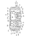
- FIG. 1 is an axial sectional view of a gas generator of the present invention.
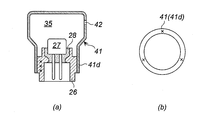
- FIG. 2 is an explanatory diagram of a method for measuring the average Vickers hardness of the color in (a), and an explanatory diagram of a method of measuring the average Vickers hardness of the cup member in (b).
- US-A No. 6,139,055 is a method of adjusting the shape and size of the housing 52 and the adapter plug 70 and then press-fitting (pressing) the housing 52 into the adapter plug 70. There is a problem of a decrease in airtightness due to insufficient pressure (decrease in adhesion of the housing 52 to the adapter plug 70).
- the present invention has a combination of an igniter collar of an igniter and a cup member as parts, and provides a gas generator capable of further increasing the adhesion strength when the cup member is press-fitted into the igniter collar of the igniter.
- the gas generator of the present invention has a combination of an igniter collar of an igniter and an ignition means chamber cup.
- the igniter is a well-known one that is widely used as an electric igniter for a gas generator, and the igniter around the igniter body having an igniter and a conductive pin is passed through a resin used as necessary. It is surrounded by color.
- the interior of the ignition means chamber cup is an ignition means chamber, and contains the igniter and a transfer agent (enhancer agent).
- the igniter collar and the ignition means chamber cup are preferably made of carbon steel, alloy steel obtained by adding an alloy element such as nickel, chromium, tungsten, manganese, silicon, and molybdenum to carbon steel.
- Vh2 / Vh1 is in the range of 0.25 to 0.65, preferably 0.30 to 0.60, and more preferably in the range of 0.35 to 0.55.
- Vh2 / Vh1 is 1.0 or more, the press-fitting work itself is very difficult, and Vh2 / Vh1 is smaller than 1.0, but a numerical value that approximates 1.0 (for example, 0.8 or more). , Less than 1.0), since the difference in hardness between the igniter collar and the ignition means chamber cup is small, the press-fitting work is difficult, and the contact degree of the contact portion between the igniter collar and the ignition means chamber cup is sufficiently increased. I can't do that.
- the average Vickers hardness (Vh1) measured by the method described in Examples of the igniter collar is preferably 160 to 210, more preferably 170 to 200, and further preferably 175 to 195.
- the average Vickers hardness (Vh2) measured by the method described in Examples of the ignition means chamber cup is preferably 55 to 105, more preferably 60 to 100, and further preferably 65 to 95. Vh1 and Vh2 are adjusted so that Vh2 / Vh1 satisfies the above range.
- the Vickers hardness of the ignition means chamber cup can be adjusted by applying a known metal forming method such as stamping or forging to a predetermined cup shape and then annealing.
- a known metal forming method such as stamping or forging
- a method of holding at 600 to 900 ° C., more preferably 700 to 800 ° C. for about 2 hours can be applied.
- the Vickers hardness of the igniter collar is that of the metal itself to be used, but the Vickers hardness may be adjusted by performing the annealing treatment as necessary.
- the Vickers hardness is measured by a known measurement method, and the average value of three measurements is defined as the average Vickers hardness.
- a Vickers microhardness meter is used at room temperature and measured with a test load of 300 g, and the average of three times is defined as the average Vickers hardness.
- an igniter collar of an igniter is press-fitted and attached to an opening of an ignition means chamber cup filled with a predetermined amount of a transfer agent (or a gas generating agent functioning as a transfer agent) inside;
- a method in which an ignition means chamber cup filled with a required amount of a transfer charge is press-fitted and attached from the opening side with the igniter collar of the igniter fixed upward;
- the ignition means chamber cup is composed of two parts, a cylindrical part and a lid part (bottom part).
- a method of fixing with laser welding or the like after filling with a charge transfer agent and then attaching a lid to the other end opening in the open state. can be applied.
- the ratio (Vh2 / Vh1) of the Vickers hardness between the igniter collar and the ignition means chamber cup is adjusted to satisfy a predetermined range. For this reason, for example, when the igniter collar is press-fitted from the opening of the ignition means chamber cup, the opening wall is expanded and deformed outward, so that the igniter collar can be easily press-fitted. However, the degree of contact between the ignition means chamber cup and the igniter collar is improved.
- the gas generator of the present invention has a combination of an igniter collar of an igniter and an ignition means chamber cup, and a combination of an igniter collar of an igniter and a combustion chamber cup.
- the first igniter and the second igniter are well-known ones that are widely used as an electric igniter for a gas generator, and the periphery of an igniter body having an ignition part and a conductive pin is used as necessary. It is surrounded by an igniter collar (first igniter color, second igniter color) via resin.
- the interior of the ignition means chamber cup is an ignition means chamber, and contains the first igniter and a transfer agent (enhancer agent).
- the interior of the combustion chamber cup is a combustion chamber, and the second igniter and the gas generating agent are accommodated therein.
- the igniter collar, ignition means chamber cup, and combustion chamber cup are preferably made of carbon steel, alloy steel obtained by adding alloy elements such as nickel, chromium, tungsten, manganese, silicon, and molybdenum to carbon steel.
- Vh2 / Vh1 is in the range of 0.25 to 0.65, preferably 0.30 to 0.60, and more preferably in the range of 0.35 to 0.55.
- Vh2 / Vh1 is 1.0 or more, the press-fitting work itself is very difficult, and Vh2 / Vh1 is smaller than 1.0, but a numerical value that approximates 1.0 (for example, 0.8 or more). , Less than 1.0), since the difference in hardness between the igniter collar and the ignition means chamber cup is small, the press-fitting work is difficult, and the contact degree of the contact portion between the igniter collar and the ignition means chamber cup is sufficiently increased. I can't do that.
- the average Vickers hardness (Vh1) measured by the method described in the embodiment of the igniter collar is preferably 160 to 210, more preferably 170 to 200, and 175 to 195 is more preferred.
- the average Vickers hardness (Vh2) measured by the method described in Examples of the ignition means chamber cup and the combustion chamber cup is preferably 55 to 105, more preferably 60 to 100, and further preferably 65 to 95. Vh1 and Vh2 are adjusted so that Vh2 / Vh1 satisfies the above range.
- a first igniter collar of the first igniter is press-fitted into the opening with the ignition means chamber cup filled with a predetermined amount of the transfer powder (or a gas generating agent functioning as a transfer powder) inside.
- a method in which an ignition means chamber cup filled with a required amount of transfer charge is press-fitted and attached from the opening side with the first igniter collar of the first igniter fixed upward.
- an ignition means chamber cup consisting of two parts, a cylindrical part and a lid part (bottom part), after press-fitting into the first igniter collar of the first igniter from the opening on one end side of the cylindrical part, A method of fixing with laser welding or the like after filling a transfer agent from the end opening, and then attaching a lid to the other end opening in the open state. Can be applied.
- a method of attaching the second igniter collar of the second igniter by press-fitting to the opening with the combustion chamber cup filled with a predetermined amount of gas generating agent inside, or the second igniter first A method in which a combustion chamber cup filled with a required amount of a gas generating agent is press-fitted from the opening side with the two igniter collars fixed upward; Use a combustion chamber cup consisting of two parts, a cylindrical part and a bottom cover part, and press fit into the second igniter collar of the second igniter from the opening on one end side of the cylindrical part, then the other end A method of fixing by laser welding or the like after filling a gas generating agent from the opening, and then attaching a lid to the other end opening in the open state, Can be applied.
- the ratio (Vh2 / Vh1) of the Vickers hardness of the igniter collar (first igniter collar, second igniter collar) to the ignition means chamber cup and the combustion chamber cup is adjusted to satisfy a predetermined range. .
- the igniter collar first igniter collar, second igniter collar
- the opening wall is expanded and deformed outward. Therefore, press-fitting of the igniter collar (first igniter collar, second igniter collar) is facilitated, and after the press-fitting, the opening wall shrinks and returns to the original shape, so that the ignition means chamber is restored.
- the contact degree of the contact portion between the cup or the combustion chamber cup and the igniter collar (first igniter collar, second igniter collar) is also increased.
- the gas generator of the present invention has good adhesion between the cup member for forming the ignition means chamber or the combustion chamber and the igniter collar into which the cup member is press-fitted, and the workability during the press-fitting is also good.
- the present invention can be applied to any gas generator having a structure in which a cup member and an igniter collar of an igniter are assembled by press fitting.
- the present invention relates to JP-A No. JP-A 2010-892, a gas generator having a combination of the first cup member 32 and the first igniter collar 22 and the second cup member 41 and the second igniter collar 26 shown in FIG. No. No. 2010-70073, the combination of the combustion chamber cup 30 and collar 41 shown in FIG.
- This can be applied to a gas generator having a combination of the cup 132 and the collar 122 and a combination of the cup 141 and the collar 126 in FIG. 3 of 2007-118788.
- FIG. 1 ame as FIG. 1 of JP-A No. 2010-892
- the gas generator 10 has an outer shell formed by a housing 11 in which a diffuser shell 12 and a closure shell 13 are welded together at a joint 16.
- a plurality of gas discharge ports 14 are provided on the peripheral surface of the diffuser shell 12, and the gas discharge ports 14 are closed from the inside with a seal tape 15 made of aluminum or stainless steel.
- the first ignition means 21 has a first igniter 23 fixed to the first igniter collar 22 through a resin 24.
- the second ignition means 25 has a second igniter 27 fixed to the second igniter collar 26 via a resin 28.
- the first igniter collar 22 and the second igniter collar 26, and the first igniter 23 and the second igniter 27 have the same shape and the same dimensions.
- a cylindrical filter 45 is disposed inside the housing 11, and an annular gap is provided between the outer peripheral surface of the filter 45 and the gas discharge port 14 and the seal tape 15.
- a first combustion chamber 31 is formed inside the filter 45 and is filled with a first gas generating agent (known gas generating agent) not shown.
- a first cup member (ignition means chamber cup) 32 and a second cup member (second combustion chamber cup) 41 are disposed adjacent to each other in the first combustion chamber 31.
- the first cup member 32 has a first enlarged peripheral wall portion 32c on the opening 32a side and a first reduced diameter peripheral wall portion 32d on the bottom surface 32b side, and covers the first igniter 23 from the opening 32a side. And fitted into the first igniter collar 22. The thickness of the first cup member 32 is uniform.
- the first igniter collar 22 is made of carbon steel that has not been annealed
- the first cup member (ignition means chamber cup) 32 is made of carbon steel that has been annealed.
- the ratio (Vh2 / Vh1) of the average Vickers hardness (Vh1) of the first igniter collar 22 and the average Vickers hardness (Vh2) of the first cup member (ignition means chamber cup) 32 is in the range of 0.25 to 0.65. is there.
- a first annular inclined surface 32e is formed at the boundary between the first enlarged diameter peripheral wall portion 32c and the first reduced diameter peripheral wall portion 32d, and a plurality of first communication holes 34 are formed in the first reduced diameter peripheral wall portion 32d. ing.
- the first communication hole 34 is formed at a position close to the first annular inclined surface 32 e, but it may be formed at a position closer to the bottom surface 32 b as long as it does not face the second cup member 41. Good.
- the inside of the first cup member 32 becomes an enhancer chamber (ignition means chamber) 33, and a gas generating agent (not shown) (a known enhancer agent or a gas generating agent that functions as an enhancer agent can be used) is aluminum if necessary. It is filled in a state where it is accommodated in a bag container.
- a gas generating agent by appropriately selecting the kind, composition, and shape, the gas generating agent in the first combustion chamber 31 can be ignited and burned, and the gas generated by its own combustion can also be used.
- the second cup member 41 has a second reduced diameter peripheral wall portion 41d on the opening 41a side and a second enlarged diameter peripheral wall portion 41c on the bottom surface 41b side so as to cover the second igniter 27 from the opening 41a side. And is fitted into the second igniter collar 26.
- the thickness of the second cup member 41 is uniform.
- the second igniter collar 26 is made of carbon steel that has not been annealed
- the second cup member (second combustion chamber cup) 41 is made of carbon steel that has been annealed.
- the ratio (Vh2 / Vh1) of the average Vickers hardness (Vh1) of the second igniter collar 26 to the average Vickers hardness (Vh2) of the second cup member (second combustion chamber cup) 41 is in the range of 0.25 to 0.65. It is.
- a second annular inclined surface 41e is formed at the boundary between the second reduced diameter peripheral wall portion 41d and the second enlarged diameter peripheral wall portion 41c, and a plurality of second communication holes 42 are formed in the second enlarged diameter peripheral wall portion 41c. ing.
- the plurality of second communication holes 42 are closed from the outside with a seal tape.
- the second communication hole 42 is formed at a position close to the bottom surface 41 b, but if it is a position not facing the first cup member 32, the position closer to the second annular slope 41 e or the second annular slope 41 e. It may be formed in the bottom 41b.
- interval is formed between the bottom part 41b and the top plate 12a of the diffuser shell 12.
- the inside of the second cup member 41 becomes the second combustion chamber 35, and a second gas generating agent (not shown) (a known gas generating agent can be used) is accommodated in an aluminum bag container as necessary. Filled.
- the first cup member 32 and the second cup member 41 have the same thickness and have a cross-sectional shape that can be fitted together.
- the first enlarged diameter peripheral wall portion 32c and the second reduced diameter peripheral wall portion 41d are adjacent to each other with a space in the radial direction, and the first reduced diameter peripheral wall portion 32d and the second cup member 41 are second.
- the enlarged-diameter peripheral wall portions 41c are arranged so as to be adjacent to each other at an interval in the radial direction.
- the distance between the first cup member 32 and the second cup member 41 is the outer diameter of the first cup member 32 and the second cup member 41 according to the degree of increase / decrease in the capacity of the enhancer chamber 33 and the capacity of the second combustion chamber 35. Set by increasing or decreasing. Further, by reducing the distance between the first cup member 32 and the second cup member 41, the volume of the first combustion chamber 31 can be increased. It should be noted that an interval between the first cup member 32 and the second cup member 41 is set such that the first gas generating agent does not enter the first cup member 32 and combustion in the enhancer chamber 33 does not affect the second combustion chamber 35. preferable.
- the first communication hole 34 and the second communication hole 42 are formed to have different height positions in the axial direction. By setting in this way, the combustion products are prevented from concentrating at the same height position of the filter 45.
- the first cup member 32 is press-fitted into the first igniter collar 22 so as to cover the first igniter 23 from the opening 32a side.
- the ratio (Vh2 / Vh1) of the average Vickers hardness (Vh1) of the first igniter collar 22 and the average Vickers hardness (Vh2) of the first cup member (ignition means chamber cup) 32 is 0.25 to 0.65. Since the opening 32a of the first cup member 32 is expanded and deformed outward, the first igniter collar 22 can be easily press-fitted. After the press-fitting, the opening 32a shrinks and returns to the original shape, so that the contact portion between the first igniter collar 22 and the first cup member (ignition means chamber cup) 32 is in close contact.
- the second cup member 41 is press-fitted into the second igniter collar 26 so as to cover the second igniter 27 from the opening 41a side.
- the ratio (Vh2 / Vh1) of the average Vickers hardness (Vh1) of the second igniter collar 26 and the average Vickers hardness (Vh2) of the second cup member (combustion chamber cup) 41 is 0.25 to 0.65. Since the range is satisfied, the opening 41a of the second cup member 41 is expanded and deformed outward, so that the first igniter collar 22 can be easily press-fitted. After the press-fitting, the opening 32a shrinks inward and returns to its original shape, so that the contact portion between the second igniter collar 26 and the second cup member (combustion chamber cup) 41 is in close contact.
- the gas generator is incorporated in an airbag system and installed in an automobile.
- the first igniter 23 and the second igniter 27 are configured so that the first igniter 23 operates first when only the first igniter 23 operates according to the degree of impact received by the automobile at the time of the collision.
- the second igniter 27 operates with a delay
- the first igniter 23 and the second igniter 27 may operate at the same time.
- the first igniter 23 operates first and the second ignition
- the device 27 operates with a delay
- the operation signal from the control unit is received, the first igniter 23 is activated and ignited, and the gas generating agent in the enhancer chamber 33 is ignited and burned, and combustion products (hot gas and Fire).
- the combustion product since the contact portion between the first cup member 32 and the first igniter collar 22 is in close contact, the combustion product does not leak from the contact portion.
- the combustion product enters the first combustion chamber 31 through the first communication hole 34 and ignites and burns the first gas generating agent to generate combustion gas.
- the first communication hole 34 is spaced apart from the filter 45 and is not formed at a position opposite to the second cup member 41, so that the combustion product of the enhancer agent causes the second communication chamber 35 to be in the second combustion chamber 35.
- the second gas generating agent is not ignited and combusted.
- the combustion gas generated from the first gas generating agent in the first combustion chamber 31 is filtered and cooled through the filter 45, then breaks the seal tape 15, is discharged from the gas discharge port 14, and inflates the airbag. .
- the second communication hole 42 is closed from the outside with a seal tape (not shown), the second gas generating agent in the second combustion chamber 35 is generated by the combustion gas generated by the combustion of the first gas generating agent. Will not ignite or burn.
- the second igniter 27 is activated and ignited after the first igniter 23, the second gas generating agent in the second combustion chamber 35 is ignited and burned, and combustion gas is generated. At this time, since the contact portion between the second cup member 41 and the second igniter collar 26 is in close contact, the combustion gas does not leak from the contact portion. The combustion gas breaks the seal tape (not shown) of the second communication hole 42, flows out of the second communication hole 42 into the first combustion chamber 31, is then filtered and cooled through the filter 45, and the gas discharge port 14. Is introduced into the airbag.
- Example 1 and Comparative Example 1 A method for measuring the average Vickers hardness of the first igniter collar 22 and the second igniter collar 26 is as follows. In both cases, the measurement method and the measurement value are the same, and will be described below as the measurement method of the second igniter collar 26.
- the first igniter collar 22 and the second igniter collar 26 are both made of carbon steel (C content 0.15 mass%), and both Example 1 and Comparative Example 1 are annealed. Absent.
- the Vickers microhardness meter HM-211 manufactured by Mitutoyo Corporation
- the measurement point is an intermediate position of the plate thickness at three points at different heights of the portion where the second igniter collar 26 contacts the second reduced diameter peripheral wall portion 41d of the second cup member 41 (3 in FIG. 2A). Two x marks). The results are shown in Table 1.
- a method for measuring the average Vickers hardness of the first cup member 32 and the second cup member 41 is as follows. In both cases, the measurement method and the measurement value are the same, and will be described below as the measurement method of the second cup member 41.
- the first cup member 32 and the second cup member 41 are both made of carbon steel (C content 0.08% by mass or less), and Example 1 is annealed at 800 ° C. for 2 hours after molding. However, Comparative Example 1 does not perform the annealing treatment after molding. After the second cup member 41 was cut in the radial direction by the second reduced-diameter peripheral wall portion 41d in contact with the second igniter collar 26, the cut surface was polished with a polishing machine to obtain a measurement sample at room temperature.
- Example 1 Using the combination of the first igniter collar 22 and the first cup member 32 of Example 1 and Comparative Example 1 having the average Vickers hardness shown in Table 1, the combination of the second igniter collar 26 and the second cup member 41 is used. Used to press-fit the cup member for each collar. As a result, the press-fitting work between the collar and the cup member of Example 1 was easy, and the adhesion between the collar and the cup member after press-fitting was good. On the other hand, the press-fitting operation of the collar and cup member of Comparative Example 1 is difficult compared with Example 1 because the deformation of the cup member is small, and the adhesion between the collar and the cup member after press-fitting is also reduced by deformation of the cup member. Was difficult to occur and was insufficient as compared with Example 1.
Landscapes
- Physics & Mathematics (AREA)
- Fluid Mechanics (AREA)
- Engineering & Computer Science (AREA)
- Mechanical Engineering (AREA)
- Air Bags (AREA)
Abstract
Description
自動車のエアバッグ装置などに使用するガス発生剤を備えたガス発生器では、ハウジング内において、前記ガス発生剤を着火するための電気式点火器が収容されている。
電気式点火器は、通常は、着火部と導電ピンを有する点火器本体が点火器カラーで包囲された状態のもので、点火器カラー部分においてハウジングに対して固定されている。
ハウジング内に位置している電気式点火器は、ガス発生剤に対する着火機能を高めるため、伝火薬(または伝火薬として機能するガス発生剤)と組み合わせて使用されることが多い。
JP-A No.2010-70073の段落番号0030には、燃焼室カップ30がカラー41に嵌め込まれていることが記載されているが、このカップとカラーとの密着強度を高めるような特別な手段についての記載はない。
JP-A No.2007-118788の段落番号0069には、エンハンサ室カップ部材132が第1点火器カラー122に嵌め込まれ、段落番号0070には、燃焼室カップ部材141が第2点火器カラー126に圧入されていることが記載されているが、カップとカラーとの密着強度を高めるような特別な手段についての記載はない。
本発明の発明1は、
ハウジング内において、点火器本体の周囲が点火器カラーで包囲された点火器と伝火薬が収容された点火手段室を有しているガス発生器であって、
前記点火手段室が、前記伝火薬が充填された点火手段室カップの開口部側の内周壁面が前記点火器の点火器カラーの外周壁面に密着した状態になるように圧入されて形成されたものであり、
前記点火器カラーの実施例に記載の方法により測定される平均ビッカース硬度(Vh1)と前記点火手段室カップの実施例に記載の方法により測定される平均ビッカース硬度(Vh2)の比(Vh2/Vh1)が0.25~0.65の範囲である、ガス発生器を提供する。
ハウジング内において、第1点火器本体の周囲が第1点火器カラーで包囲された第1点火器と伝火薬が収容された点火手段室と、第2点火器本体の周囲が第2点火器カラーで包囲された第2点火器とガス発生剤が収容された燃焼室を有しているガス発生器であって、
前記点火手段室が、
前記伝火薬が充填された点火手段室カップの開口部側の内周壁面が前記第1点火器の第1点火器カラーの外周壁面に密着した状態になるように圧入されて形成されたものであり、
前記第1点火器カラーの実施例に記載の方法により測定される平均ビッカース硬度(Vh1)と前記点火手段室カップの実施例に記載の方法により測定される平均ビッカース硬度(Vh2)の比(Vh2/Vh1)が0.25~0.65の範囲であり、
前記燃焼室が、
前記ガス発生剤が充填された燃焼室カップの開口部側の内周壁面が前記第2点火器の第2点火器カラーの外周壁面に密着した状態になるように圧入されて形成されたものであり、
前記第2点火器カラーの実施例に記載の方法により測定される平均ビッカース硬度(Vh1)と前記燃焼室カップの実施例に記載の方法により測定される平均ビッカース硬度(Vh2)の比(Vh2/Vh1)が0.25~0.65の範囲である、ガス発生器を提供する。
JP-A No.H05-4035の取り付け方法では、点火室カバー3の雄ネジ部3aと点火ケース2下部の雌ネジ部2cの精密なねじ切り加工が必要となることと、取り付け時のネジ合わせ加工に時間を要するという問題がある。
点火器は、ガス発生器用の電気式点火器として汎用されている周知のものであり、着火部と導電ピンを有する点火器本体の周囲が、必要に応じて使用される樹脂を介して点火器カラーで包囲されたものである。
点火手段室カップは、その内部が点火手段室となるものであり、前記点火器と伝火薬(エンハンサ剤)が収容される。
点火器カラーと点火手段室カップは、炭素鋼、炭素鋼にニッケル、クロム、タングステン、マンガン、ケイ素、モリブデンなどの合金元素を添加した合金鋼などからなるものが好ましい。
Vh2/Vh1が1.0以上である場合には、圧入作業自体の困難性が非常に高く、Vh2/Vh1が1.0よりも小さいが、1.0に近似する数値(例えば0.8以上、1.0未満)である場合には、点火器カラーと点火手段室カップの硬度差が小さいため、圧入作業が難しく、点火器カラーと点火手段室カップの接触部分の密着度も十分に高めることができなくなる。
前記点火手段室カップの実施例に記載の方法により測定される平均ビッカース硬度(Vh2)は、55~105が好ましく、60~100がより好ましく、65~95がさらに好ましい。
Vh1とVh2は、Vh2/Vh1が上記範囲を満たすように調整されるものである。
焼鈍処理は、好ましくは600~900℃、より好ましくは700~800℃で2時間程度保持する方法を適用することができる。
なお、点火器カラーのビッカース硬度は、使用する金属自体のものであるが、必要に応じて上記焼鈍処理をしてビッカース硬度を調整してもよい。
ビッカース硬度は公知の測定方法で測定され、3回測定の平均値を平均ビッカース硬度とする。本発明では、室温にてビッカース微小硬さ計を使用して、試験荷重300gで測定し、3回の平均値を平均ビッカース硬度とする。
内部に所定量の伝火薬(または伝火薬として機能するガス発生剤)が充填された点火手段室カップを下にして、その開口部に対して点火器の点火器カラーを圧入して取り付ける方法、
点火器の点火器カラーを上方に固定した状態で、所要量の伝火薬が充填された点火手段室カップを開口部側から圧入して取り付ける方法、
点火手段室カップとして筒状部と蓋部(底部)の2つからなるものを使用し、点火器の点火器カラーに筒状部の一端側の開口部から圧入した後、他端開口部から伝火薬を充填し、その後、開放状態の他端開口部に蓋部を取り付けたあと、レーザー溶接などで固定する方法、
を適用することができる。
このため、例えば、点火手段室カップの開口部から点火器カラーを圧入するとき、前記開口部壁が外側に拡張変形するため、点火器カラーの圧入が容易になり、圧入後には前記開口部壁が内側に縮小変形して元の形状に戻るため、点火手段室カップと点火器カラーの接触部分の密着度も高められる。
第1点火器と第2点火器は、ガス発生器用の電気式点火器として汎用されている周知のものであり、着火部と導電ピンを有する点火器本体の周囲が必要に応じて使用される樹脂を介して点火器カラー(第1点火器カラー、第2点火器カラー)で包囲されたものである。
点火手段室カップは、その内部が点火手段室となるものであり、前記第1点火器と伝火薬(エンハンサ剤)が収容される。
燃焼室カップは、その内部が燃焼室となるものであり、前記第2点火器とガス発生剤が収容される。
点火器カラー、点火手段室カップ、燃焼室カップは、炭素鋼、炭素鋼にニッケル、クロム、タングステン、マンガン、ケイ素、モリブデンなどの合金元素を添加した合金鋼などからなるものが好ましい。
Vh2/Vh1が1.0以上である場合には、圧入作業自体の困難性が非常に高く、Vh2/Vh1が1.0よりも小さいが、1.0に近似する数値(例えば0.8以上、1.0未満)である場合には、点火器カラーと点火手段室カップの硬度差が小さいため、圧入作業が難しく、点火器カラーと点火手段室カップの接触部分の密着度も十分に高めることができなくなる。
前記点火手段室カップおよび燃焼室カップの実施例に記載の方法により測定される平均ビッカース硬度(Vh2)は、55~105が好ましく、60~100がより好ましく、65~95がさらに好ましい。
Vh1とVh2は、Vh2/Vh1が上記範囲を満たすように調整されるものである。
内部に所定量の伝火薬(または伝火薬として機能するガス発生剤)が充填された点火手段室カップを下にして、その開口部に対して第1点火器の第1点火器カラーを圧入して取り付ける方法、または
第1点火器の第1点火器カラーを上方に固定した状態で、所要量の伝火薬が充填された点火手段室カップを開口部側から圧入して取り付ける方法、
点火手段室カップとして筒状部と蓋部(底部)の2つからなるものを使用し、第1点火器の第1点火器カラーに筒状部の一端側の開口部から圧入した後、他端開口部から伝火薬を充填し、その後、開放状態の他端開口部に蓋部を取り付けたあと、レーザー溶接などで固定する方法、
を適用することができる。
内部に所定量のガス発生剤が充填された燃焼室カップを下にして、その開口部に対して第2点火器の第2点火器カラーを圧入して取り付ける方法、または
第2点火器の第2点火器カラーを上方に固定した状態で、所要量のガス発生剤が充填された燃焼室カップを開口部側から圧入して取り付ける方法、
燃焼室カップとして筒状部と底部となる蓋部の2つからなるものを使用し、第2点火器の第2点火器カラーに筒状部の一端側の開口部から圧入した後、他端開口部からガス発生剤を充填し、その後、開放状態の他端開口部に蓋部を取り付けたあと、レーザー溶接などで固定する方法、
を適用することができる。
このため、例えば、点火手段室カップの開口部または燃焼室カップの開口部から点火器カラー(第1点火器カラー、第2点火器カラー)を圧入するとき、前記開口部壁が外側に拡張変形するため、点火器カラーの圧入(第1点火器カラー、第2点火器カラー)が容易になり、圧入後には前記開口部壁が内側に縮小変形して元の形状に戻るため、点火手段室カップまたは燃焼室カップと点火器カラー(第1点火器カラー、第2点火器カラー)の接触部分の密着度も高められる。
本発明は、カップ部材と点火器の点火器カラーを圧入で組み立てる構造のガス発生器であれば適用することができる。
例えば本発明は、JP-A No.2010-892の図1に示されている第1カップ部材32と第1点火器カラー22、第2カップ部材41と第2点火器カラー26の組み合わせを有しているガス発生器、JP-A No.2010-70073の図1に示されている燃焼室カップ30とカラー41の組み合わせ、JP-A No.2007-118788の図3のカップ132とカラー122の組み合わせ、カップ141とカラー126の組み合わせを有しているガス発生器などに適用することができる。
以下、図1(JP-A No.2010-892の図1と同じもの)により説明する。
第1点火手段21は、樹脂24を介して第1点火器カラー22に固定された第1点火器23を有している。
第2点火手段25は、樹脂28を介して第2点火器カラー26に固定された第2点火器27を有している。
第1燃焼室31内には、第1カップ部材(点火手段室カップ)32と第2カップ部材(第2燃焼室カップ)41が隣接配置されている。
第1点火器カラー22の平均ビッカース硬度(Vh1)と第1カップ部材(点火手段室カップ)32の平均ビッカース硬度(Vh2)の比(Vh2/Vh1)は0.25~0.65の範囲である。
ガス発生剤は、適宜種類、組成、形状を選択することにより、第1燃焼室31内のガス発生剤を着火燃焼させる作用と、それ自体の燃焼により発生するガスも利用するようにもできる。
第2点火器カラー26の平均ビッカース硬度(Vh1)と第2カップ部材(第2燃焼室カップ)41の平均ビッカース硬度(Vh2)の比(Vh2/Vh1)は0.25~0.65の範囲である。
図1では、第2連通孔42は底面41bに近い位置に形成されているが、第1カップ部材32と対向しない位置であれば、より第2環状斜面41eに近い位置や第2環状斜面41eに形成されていてもよいし、底部41bに形成されていてもよい。底部41bに形成するときには、底部41bとディフューザシェル12の天板12aとの間に間隔を形成する。
また、第1カップ部材32と第2カップ部材41の間隔を狭くすることで、第1燃焼室31の容積を増加させることができる。
なお、第1カップ部材32と第2カップ部材41の間は、そこに第1ガス発生剤が入り込まず、エンハンサ室33での燃焼が第2燃焼室35に影響しないような間隔にすることが好ましい。
このとき、第1点火器カラー22の平均ビッカース硬度(Vh1)と第1カップ部材(点火手段室カップ)32の平均ビッカース硬度(Vh2)の比(Vh2/Vh1)が0.25~0.65の範囲を満たしているため、第1カップ部材32の開口部32aが外側に拡張変形することから、第1点火器カラー22の圧入が容易になる。圧入後には開口部32aが内側に縮小変形して元の形状に戻るため、第1点火器カラー22と第1カップ部材(点火手段室カップ)32の接触部分は密着される。
このとき、第2点火器カラー26の平均ビッカース硬度(Vh1)と第2カップ部材(燃焼室カップ)41の平均ビッカース硬度(Vh2)の比(Vh2/Vh1)が0.25~0.65の範囲を満たしているため、第2カップ部材41の開口部41aが外側に拡張変形することから、第1点火器カラー22の圧入が容易になる。圧入後には開口部32aが内側に縮小変形して元の形状に戻るため、第2点火器カラー26と第2カップ部材(燃焼室カップ)41の接触部分は密着される。
ガス発生器はエアバッグシステムに組み込まれ、自動車に搭載されている場合を例にする。なお、第1点火器23と第2点火器27は、衝突時において自動車が受ける衝撃の程度に応じて、第1点火器23のみが作動する場合、第1点火器23が先に作動して第2点火器27が遅れて作動する場合、第1点火器23と第2点火器27が同時に作動する場合があるが、以下においては、第1点火器23が先に作動して第2点火器27が遅れて作動する場合について説明する。
前記燃焼生成物は、第1連通孔34を通って第1燃焼室31に入り、第1ガス発生剤を着火、燃焼させて燃焼ガスを発生させる。このとき、第1連通孔34は、フィルタ45と距離を置いており、また第2カップ部材41とも対向する位置には形成されていないため、エンハンサ剤の燃焼生成物によって第2燃焼室35内の第2ガス発生剤が着火燃焼されることはない。
燃焼ガスは、第2連通孔42のシールテープ(図示せず)を破り、第2連通孔42から第1燃焼室31に流出したあと、フィルタ45を通って濾過及び冷却され、ガス排出口14からエアバッグに導入される。
実施例1および比較例1
第1点火器カラー22と第2点火器カラー26の平均ビッカース硬度の測定方法は、次のとおりである。なお、いずれも測定方法と測定値は同じであり、以下においては第2点火器カラー26の測定方法として説明する。
第1点火器カラー22と第2点火器カラー26は、いずれも炭素鋼(C含有量0.15質量%)からなるものであり、実施例1および比較例1の両方とも焼鈍処理はしていない。
第2点火器カラー26を軸方向に切断した後、切断面を研磨機で平滑になるように研磨したものを測定試料として、室温にてビッカース微小硬さ計((株)ミツトヨ製HM-211型)を使用して試験荷重300gで測定した。
測定個所は、第2点火器カラー26が第2カップ部材41の第2縮径周壁部41dと接触する部分の高さの異なる3点における板厚の中間位置(図2(a)中の3つの×印の位置)である。結果を表1に示す。
第1カップ部材32と第2カップ部材41は、いずれも炭素鋼(C含有量0.08質量%以下)からなるものであり、実施例1は成形後に800℃で2時間焼鈍処理をしているが、比較例1は成形後の焼鈍処理はしていない。
第2カップ部材41を第2点火器カラー26と接触する第2縮径周壁部41dで半径方向に切断した後、切断面を研磨機で平滑になるように研磨したものを測定試料として、室温にてビッカース微小硬さ計((株)ミツトヨ製HM-211型)を使用して試験荷重300gで測定した。
測定個所は、周方向に等間隔の3点における板厚の中間位置(図2(b)中の3つの×印の位置)である。結果を表1に示す。

その結果、実施例1のカラーとカップ部材の圧入作業は容易であり、圧入後におけるカラーとカップ部材の密着性も良かった。
一方、比較例1のカラーとカップ部材の圧入作業は、カップ部材の拡大変形が小さく、実施例1と比べると困難であり、圧入後におけるカラーとカップ部材の密着性も、カップ部材の縮小変形が生じ難く、実施例1と比べると不十分であった。
Claims (4)
- ハウジング内において、点火器本体の周囲が点火器カラーで包囲された点火器と伝火薬が収容された点火手段室を有しているガス発生器であって、
前記点火手段室が、前記伝火薬が充填された点火手段室カップの開口部側の内周壁面が前記点火器の点火器カラーの外周壁面に密着した状態になるように圧入されて形成されたものであり、
前記点火器カラーの実施例に記載の方法により測定される平均ビッカース硬度(Vh1)と前記点火手段室カップの実施例に記載の方法により測定される平均ビッカース硬度(Vh2)の比(Vh2/Vh1)が0.25~0.65の範囲である、ガス発生器。 - 実施例に記載の方法により測定される前記点火手段室カップの平均ビッカース硬度(Vh2)が55~105である、請求項1記載のガス発生器。
- ハウジング内において、第1点火器本体の周囲が第1点火器カラーで包囲された第1点火器と伝火薬が収容された点火手段室と、第2点火器本体の周囲が第2点火器カラーで包囲された第2点火器とガス発生剤が収容された燃焼室を有しているガス発生器であって、
前記点火手段室が、
前記伝火薬が充填された点火手段室カップの開口部側の内周壁面が前記第1点火器の第1点火器カラーの外周壁面に密着した状態になるように圧入されて形成されたものであり、
前記第1点火器カラーの実施例に記載の方法により測定される平均ビッカース硬度(Vh1)と前記点火手段室カップの実施例に記載の方法により測定される平均ビッカース硬度(Vh2)の比(Vh2/Vh1)が0.25~0.65の範囲であり、
前記燃焼室が、
前記ガス発生剤が充填された燃焼室カップの開口部側の内周壁面が前記第2点火器の第2点火器カラーの外周壁面に密着した状態になるように圧入されて形成されたものであり、
前記第2点火器カラーの実施例に記載の方法により測定される平均ビッカース硬度(Vh1)と前記燃焼室カップの実施例に記載の方法により測定される平均ビッカース硬度(Vh2)の比(Vh2/Vh1)が0.25~0.65の範囲である、ガス発生器。 - 実施例に記載の方法により測定される前記点火手段室カップと前記燃焼室カップの平均ビッカース硬度(Vh2)が55~105である、請求項3記載のガス発生器。
Priority Applications (4)
| Application Number | Priority Date | Filing Date | Title |
|---|---|---|---|
| CN201580003296.5A CN105873800B (zh) | 2014-01-09 | 2015-01-05 | 气体发生器 |
| DE112015000371.1T DE112015000371T5 (de) | 2014-01-09 | 2015-01-05 | Gasgenerator |
| KR1020167018124A KR102204062B1 (ko) | 2014-01-09 | 2015-01-05 | 가스 발생기 |
| US15/104,566 US9944249B2 (en) | 2014-01-09 | 2015-01-05 | Gas generator |
Applications Claiming Priority (2)
| Application Number | Priority Date | Filing Date | Title |
|---|---|---|---|
| JP2014-002229 | 2014-01-09 | ||
| JP2014002229A JP6483949B2 (ja) | 2014-01-09 | 2014-01-09 | ガス発生器 |
Publications (1)
| Publication Number | Publication Date |
|---|---|
| WO2015105067A1 true WO2015105067A1 (ja) | 2015-07-16 |
Family
ID=53523894
Family Applications (1)
| Application Number | Title | Priority Date | Filing Date |
|---|---|---|---|
| PCT/JP2015/050024 Ceased WO2015105067A1 (ja) | 2014-01-09 | 2015-01-05 | ガス発生器 |
Country Status (6)
| Country | Link |
|---|---|
| US (1) | US9944249B2 (ja) |
| JP (1) | JP6483949B2 (ja) |
| KR (1) | KR102204062B1 (ja) |
| CN (1) | CN105873800B (ja) |
| DE (1) | DE112015000371T5 (ja) |
| WO (1) | WO2015105067A1 (ja) |
Families Citing this family (10)
| Publication number | Priority date | Publication date | Assignee | Title |
|---|---|---|---|---|
| JP6353326B2 (ja) * | 2014-09-16 | 2018-07-04 | 株式会社ダイセル | ガス発生器 |
| WO2017130735A1 (ja) * | 2016-01-26 | 2017-08-03 | 株式会社ダイセル | ガス発生器 |
| KR102288663B1 (ko) * | 2016-08-29 | 2021-08-11 | 주식회사 다이셀 | 가스 발생기 |
| JP6954520B2 (ja) * | 2017-12-05 | 2021-10-27 | 株式会社ダイセル | 点火器組立体、及びガス発生器 |
| KR102622079B1 (ko) * | 2018-05-29 | 2024-01-09 | 주식회사 다이셀 | 가스 발생기 |
| KR102579301B1 (ko) * | 2018-12-11 | 2023-09-15 | 현대자동차주식회사 | 차량의 동승석 에어백 인플레이터 및 시스템 |
| DE102019134899A1 (de) * | 2019-12-18 | 2021-06-24 | Zf Airbag Germany Gmbh | Gasgenerator insbesondere für ein fahrzeugsicherheitssystem |
| JP7495306B2 (ja) * | 2020-09-11 | 2024-06-04 | 株式会社ダイセル | 点火装置組立体及び点火装置 |
| US11603072B2 (en) * | 2021-08-06 | 2023-03-14 | Autoliv Asp, Inc. | Dual stage inflator |
| CN115782806B (zh) * | 2022-11-25 | 2026-01-06 | 延锋汽车智能安全系统有限责任公司 | 点火系统及其制造方法、气体发生器和安全气囊 |
Citations (3)
| Publication number | Priority date | Publication date | Assignee | Title |
|---|---|---|---|---|
| JP2002216888A (ja) * | 2001-01-22 | 2002-08-02 | Hataya Seisakusho:Kk | プラグ用防水カバー及びその防水カバーの装着用ガイド、並びにプラグ用防水カバーの装着方法 |
| JP2005337475A (ja) * | 2004-05-31 | 2005-12-08 | Denso Corp | 電磁弁装置 |
| JP2010000892A (ja) * | 2008-06-20 | 2010-01-07 | Daicel Chem Ind Ltd | ガス発生器 |
Family Cites Families (15)
| Publication number | Priority date | Publication date | Assignee | Title |
|---|---|---|---|---|
| JPH054035A (ja) | 1990-08-31 | 1993-01-14 | Nippon Oil & Fats Co Ltd | ガス発生器用容器及びその製造方法並びにガス発生器 |
| FR2691706B1 (fr) * | 1992-06-02 | 1994-07-22 | Livbag Snc | Generateur pyrotechnique de gaz muni d'une ouverture de securite. |
| US6474684B1 (en) | 1997-04-24 | 2002-11-05 | Talley Defense Systems, Inc. | Dual stage inflator |
| US6139055A (en) | 1999-05-10 | 2000-10-31 | Autoliv Asp, Inc. | Adaptive heated stage inflator |
| JP4037300B2 (ja) * | 2003-03-26 | 2008-01-23 | ダイセル化学工業株式会社 | 点火器組立体 |
| US20040251667A1 (en) | 2003-03-26 | 2004-12-16 | Hiroshi Harada | Ignitor assembly |
| JP4177311B2 (ja) * | 2004-09-13 | 2008-11-05 | 古河電気工業株式会社 | 流体輸送管の端末金具 |
| US7850201B2 (en) | 2005-01-21 | 2010-12-14 | Nippon Kayaku Kabushiki Kaisha | Gas generator and method of manufacturing the same |
| JP2007118788A (ja) | 2005-10-28 | 2007-05-17 | Daicel Chem Ind Ltd | エアバッグ用ガス発生器 |
| JP5301128B2 (ja) * | 2007-09-12 | 2013-09-25 | Ntn株式会社 | 車輪用軸受装置 |
| JP5255967B2 (ja) | 2008-09-19 | 2013-08-07 | 株式会社ダイセル | ガス発生器 |
| CN102414058A (zh) | 2009-04-30 | 2012-04-11 | 日本化药株式会社 | 气体发生器 |
| JP2011143777A (ja) | 2010-01-13 | 2011-07-28 | Nippon Kayaku Co Ltd | ガス発生器 |
| JP5450306B2 (ja) * | 2010-07-29 | 2014-03-26 | 株式会社ダイセル | ガス発生器 |
| JP5985950B2 (ja) * | 2012-10-04 | 2016-09-06 | 株式会社ダイセル | ガス発生器とその組立方法 |
-
2014
- 2014-01-09 JP JP2014002229A patent/JP6483949B2/ja active Active
-
2015
- 2015-01-05 WO PCT/JP2015/050024 patent/WO2015105067A1/ja not_active Ceased
- 2015-01-05 US US15/104,566 patent/US9944249B2/en active Active
- 2015-01-05 DE DE112015000371.1T patent/DE112015000371T5/de not_active Withdrawn
- 2015-01-05 CN CN201580003296.5A patent/CN105873800B/zh active Active
- 2015-01-05 KR KR1020167018124A patent/KR102204062B1/ko active Active
Patent Citations (3)
| Publication number | Priority date | Publication date | Assignee | Title |
|---|---|---|---|---|
| JP2002216888A (ja) * | 2001-01-22 | 2002-08-02 | Hataya Seisakusho:Kk | プラグ用防水カバー及びその防水カバーの装着用ガイド、並びにプラグ用防水カバーの装着方法 |
| JP2005337475A (ja) * | 2004-05-31 | 2005-12-08 | Denso Corp | 電磁弁装置 |
| JP2010000892A (ja) * | 2008-06-20 | 2010-01-07 | Daicel Chem Ind Ltd | ガス発生器 |
Also Published As
| Publication number | Publication date |
|---|---|
| US9944249B2 (en) | 2018-04-17 |
| CN105873800B (zh) | 2019-06-21 |
| JP6483949B2 (ja) | 2019-03-13 |
| US20160362082A1 (en) | 2016-12-15 |
| JP2015128974A (ja) | 2015-07-16 |
| KR20160106592A (ko) | 2016-09-12 |
| DE112015000371T5 (de) | 2016-10-06 |
| KR102204062B1 (ko) | 2021-01-18 |
| CN105873800A (zh) | 2016-08-17 |
Similar Documents
| Publication | Publication Date | Title |
|---|---|---|
| JP6483949B2 (ja) | ガス発生器 | |
| US9731679B2 (en) | Gas generator and assembling method thereof | |
| JP6031250B2 (ja) | ガス発生器 | |
| US9950688B2 (en) | Gas generator | |
| US9487182B2 (en) | Gas generator for restraining device | |
| US10773682B2 (en) | Ignition device and gas generator using same | |
| US10974687B2 (en) | Gas generator | |
| US10981534B2 (en) | Gas generator | |
| EP2487075A1 (en) | Method of manufacturing perforated pipe for gas generator, as well as gas generator | |
| JP6585467B2 (ja) | 点火器組立体とそれを使用したガス発生器 | |
| US20110248486A1 (en) | Gas generator and method for assembling same | |
| US10814827B2 (en) | Gas generator | |
| US10723308B2 (en) | Gas generator | |
| US10875489B2 (en) | Gas generator | |
| KR20170055472A (ko) | 가스 발생기 | |
| JP6375482B2 (ja) | ガス発生器 | |
| WO2016076149A1 (ja) | 点火器組立体とそれを使用したガス発生器 |
Legal Events
| Date | Code | Title | Description |
|---|---|---|---|
| 121 | Ep: the epo has been informed by wipo that ep was designated in this application |
Ref document number: 15735515 Country of ref document: EP Kind code of ref document: A1 |
|
| WWE | Wipo information: entry into national phase |
Ref document number: 15104566 Country of ref document: US |
|
| ENP | Entry into the national phase |
Ref document number: 20167018124 Country of ref document: KR Kind code of ref document: A |
|
| WWE | Wipo information: entry into national phase |
Ref document number: 112015000371 Country of ref document: DE |
|
| 122 | Ep: pct application non-entry in european phase |
Ref document number: 15735515 Country of ref document: EP Kind code of ref document: A1 |