WO2015104893A1 - アキシャルギャップ型モータ - Google Patents
アキシャルギャップ型モータ Download PDFInfo
- Publication number
- WO2015104893A1 WO2015104893A1 PCT/JP2014/079701 JP2014079701W WO2015104893A1 WO 2015104893 A1 WO2015104893 A1 WO 2015104893A1 JP 2014079701 W JP2014079701 W JP 2014079701W WO 2015104893 A1 WO2015104893 A1 WO 2015104893A1
- Authority
- WO
- WIPO (PCT)
- Prior art keywords
- winding
- type motor
- gap type
- axial gap
- winding coil
- Prior art date
- Legal status (The legal status is an assumption and is not a legal conclusion. Google has not performed a legal analysis and makes no representation as to the accuracy of the status listed.)
- Ceased
Links
Images




Classifications
-
- H—ELECTRICITY
- H02—GENERATION; CONVERSION OR DISTRIBUTION OF ELECTRIC POWER
- H02K—DYNAMO-ELECTRIC MACHINES
- H02K1/00—Details of the magnetic circuit
- H02K1/06—Details of the magnetic circuit characterised by the shape, form or construction
- H02K1/12—Stationary parts of the magnetic circuit
- H02K1/18—Means for mounting or fastening magnetic stationary parts on to, or to, the stator structures
- H02K1/182—Means for mounting or fastening magnetic stationary parts on to, or to, the stator structures to stators axially facing the rotor, i.e. with axial or conical air gap
-
- H—ELECTRICITY
- H02—GENERATION; CONVERSION OR DISTRIBUTION OF ELECTRIC POWER
- H02K—DYNAMO-ELECTRIC MACHINES
- H02K1/00—Details of the magnetic circuit
- H02K1/06—Details of the magnetic circuit characterised by the shape, form or construction
- H02K1/12—Stationary parts of the magnetic circuit
- H02K1/16—Stator cores with slots for windings
-
- H—ELECTRICITY
- H02—GENERATION; CONVERSION OR DISTRIBUTION OF ELECTRIC POWER
- H02K—DYNAMO-ELECTRIC MACHINES
- H02K1/00—Details of the magnetic circuit
- H02K1/06—Details of the magnetic circuit characterised by the shape, form or construction
- H02K1/22—Rotating parts of the magnetic circuit
- H02K1/27—Rotor cores with permanent magnets
- H02K1/2793—Rotors axially facing stators
- H02K1/2795—Rotors axially facing stators the rotor consisting of two or more circumferentially positioned magnets
-
- H—ELECTRICITY
- H02—GENERATION; CONVERSION OR DISTRIBUTION OF ELECTRIC POWER
- H02K—DYNAMO-ELECTRIC MACHINES
- H02K15/00—Processes or apparatus specially adapted for manufacturing, assembling, maintaining or repairing of dynamo-electric machines
- H02K15/04—Processes or apparatus specially adapted for manufacturing, assembling, maintaining or repairing of dynamo-electric machines of windings prior to their mounting into the machines
- H02K15/043—Processes or apparatus specially adapted for manufacturing, assembling, maintaining or repairing of dynamo-electric machines of windings prior to their mounting into the machines winding flat conductive wires or sheets
- H02K15/0431—Concentrated windings
-
- H—ELECTRICITY
- H02—GENERATION; CONVERSION OR DISTRIBUTION OF ELECTRIC POWER
- H02K—DYNAMO-ELECTRIC MACHINES
- H02K21/00—Synchronous motors having permanent magnets; Synchronous generators having permanent magnets
- H02K21/12—Synchronous motors having permanent magnets; Synchronous generators having permanent magnets with stationary armatures and rotating magnets
- H02K21/24—Synchronous motors having permanent magnets; Synchronous generators having permanent magnets with stationary armatures and rotating magnets with magnets axially facing the armatures, e.g. hub-type cycle dynamos
-
- H—ELECTRICITY
- H02—GENERATION; CONVERSION OR DISTRIBUTION OF ELECTRIC POWER
- H02K—DYNAMO-ELECTRIC MACHINES
- H02K3/00—Details of windings
- H02K3/04—Windings characterised by the conductor shape, form or construction, e.g. with bar conductors
- H02K3/18—Windings for salient poles
-
- H—ELECTRICITY
- H02—GENERATION; CONVERSION OR DISTRIBUTION OF ELECTRIC POWER
- H02K—DYNAMO-ELECTRIC MACHINES
- H02K2213/00—Specific aspects, not otherwise provided for and not covered by codes H02K2201/00 - H02K2211/00
- H02K2213/03—Machines characterised by numerical values, ranges, mathematical expressions or similar information
Definitions
- the present invention relates to an axial gap type motor, and in particular, an axial gap type motor in which a slot combination of a rotor and a stator has a core (slot) number which is a multiple of 9 like an 8 pole 9 core (slot). Winding technology suitable for
- an axial gap type motor which can realize high efficiency of the motor only by a ferrite magnet without using a rare earth magnet has attracted attention.
- the magnet area can be made larger than that of the radial gap type motor, and it is possible to compensate for the decrease in holding power due to the ferrite magnet.
- an axial gap type motor has a plurality of cores, a stator having a winding wound around the cores, and two rotors on both sides in the axial direction. ing.
- Patent Document 1 JP-A-46-7928
- Patent Document 2 JP-A-2012-50250
- the first space at the center of the cylindrical shape and the circumference equidistant from the center
- a storage frame having a plurality of second spaces, a shaft rotatably provided in the first space, a core disposed in the second space and a coil wound around the core, and fixed to the shaft
- An axial gap type rotating electric machine comprising a rotor yoke having a plurality of magnets disposed at circumferential positions opposed to the core, and a case having a hole through which a shaft is inserted and a housing frame and a rotor yoke housed therein Described (see summary).
- Patent Document 1 discloses a single-phase synchronous generator having an axial gap structure including eight pole pieces and eight poles of the rotor.
- the windings have the same number of magnetic poles of the pole piece and the rotor, and therefore, the forward direction, the reverse direction, the forward direction corresponding to the magnetic poles (N pole S pole) of the rotor It is guessed that it is wound in the reverse direction ... continuously.
- Patent Document 2 discloses an axial gap rotary electric machine having 9 cores and 8 poles of a rotor, but does not disclose a winding method such as star connection and delta connection of coil windings.
- a wiring operation such as a connecting wire of a winding or a neutral point connection.
- a wire such as a crossover wire on the gap surface between the stator core and the permanent magnet
- the performance of the motor is significantly reduced.
- the outer diameter of the stator is increased for wiring, the motor becomes larger.
- an object of the present invention is to provide an axial gap type in which a continuously wound coil can be easily assembled as a stator coil of an axial gap type motor, and winding workability without a crossover in the gap surface can be improved. It is about providing a motor.
- the axial gap type motor according to the present invention is, for example, an axial gap type motor in which the number of slots (cores) is a multiple of nine, such as a slot combination of 8 poles and 9 slots (core). Construct as a single piece and wind the winding coil three times with one conductor.
- the continuous winding coil can be easily assembled as a stator coil of an axial gap type motor, and a connecting wire is disposed between the cores to form a gap surface between the stator core and the permanent magnet.
- a connecting wire is disposed between the cores to form a gap surface between the stator core and the permanent magnet.
- FIG. 1 is a cross-sectional view of an axial gap type motor 1 according to the present embodiment.
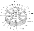
- FIG. 2 is a perspective view of the stator 2 according to the present embodiment.
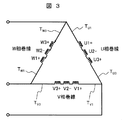
- FIG. 3 is a connection diagram of a stator winding according to the present embodiment.
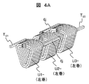
- FIG. 4 is an explanatory view of an assembling procedure of a coil for one phase according to the present embodiment,
- FIG. 4A is a diagram showing the first procedure,
- FIG. 4B is a diagram showing the second procedure, and
- FIG. It is a figure which shows a procedure.
- the axial gap type motor 1 comprises a stator 2 formed in a flat cylindrical shape, and a pair of permanent magnet rotors 3 disposed opposite to each other with a predetermined air gap on both sides in the axial direction of the stator 2, It has 31 and.
- the permanent magnet rotors 3 and 31 are fixed to an output shaft 4 that outputs a rotational drive force.
- the stator 2 and the permanent magnet rotors 3 and 31 are accommodated in the housing 5.
- the permanent magnet rotors 3 and 31 are disposed on both sides in the axial direction with the stator 2 interposed therebetween, but only one of them may be used, and in the present embodiment, the configuration of the permanent magnet rotor is It suffices to have the functions necessary to configure the axial gap type motor 1.
- a plurality of cores 21 (21a to 21i) are disposed in the circumferential direction with the rotation axis 4 as an output axis as a central axis.
- Winding coils 6 (U1 +, U2-, U3 +, V1 +, V2-, V3 +, W1 +, W2-, W3 +) are wound around the outer periphery of the core 21 (21a to 21i).
- a winding coil U1 + is wound around the core 21a
- a winding coil U2- is wound around the core 21b
- a winding coil U3 + is wound around the core 21c
- a winding coil V1 + is wound around the core 21d.
- a winding coil V2- is wound around the core 21e
- a winding coil V3 + is wound around the core 21f
- a winding coil W1 + is wound around the core 21g
- a winding coil is wound around the core 21h W2- is wound
- a winding coil W3 + is wound around the core 21i. That is, in the present embodiment, a configuration of 9 slots having 9 cores is adopted, and 3 winding coils are disposed for each of U, V and W phases.
- a pair of bearings 221 and 222 is disposed at the center of the stator 2.
- the bearings 221 and 222 are ball bearings
- the inner ring is inserted into the output shaft 4
- the outer ring is inserted into the bearing holder 24.
- the configuration of the bearings 221 and 222 is not limited to the ball bearings, and bearings other than ball bearings such as rolling bearings and sliding bearings may be adopted.
- the number is not limited to two.
- U-phase windings (U1 +, U2-, U3 +), V-phase windings (V1 +, V2-, V3 +), W are provided on the outer periphery of cores (slots) 21a to 21i of the stator 2 of the axial gap type motor 1
- the phase windings (W1 +, W2-, W3 +) are wound, and the cores 21a to 21i are arranged in the circumferential direction of the stator 2.
- connection method of the nine winding coils 6 (U1 +, U2-, U3 +, V1 +, V2-, V3 +, W1 +, W2-, W3 +) of FIG. 2 can be, for example, the delta connection shown in FIG.
- the driving power supply is a battery, and thus the voltage is as low as 12V. Therefore, the terminal voltage of the winding coil 6 can be increased by ⁇ ⁇ ⁇ 3 times in the delta connection as compared with the star connection.
- the phase current can be reduced at the same output, so that the diameter of the winding coil 6 can be reduced.
- the winding operation can be facilitated, and the space factor of the winding coil 6 between the cores can be improved.
- the axial gap type motor 1 can be provided with high efficiency.
- the winding operation of the stator in the form shown in FIGS. 2 and 3 includes U-phase winding (U3 +, U2-, U1 +), V-phase winding (V3 +, V2-, V1 +), W-phase winding (W3 +) , W2-, W1 +), and the three windings constituting each phase are continuously wound by one wire as shown in FIGS. 4A to 4C.
- T W3 , T U1 , T U3 , T V1 , T V3 and T W1 which are lead wire portions of the axial gap type motor 1 can be formed as illustrated to facilitate the connection with the outside. .
- the lead wires T W3 and T U1 , T U3 and T V1 , and T V3 and T W1 are connected by pressure bonding etc., for example, to the outside as U phase, V phase and W phase like a three phase brushless motor. It can be used as a wiring for connection with an inverter (not shown) for drawing out and driving a motor.
- connection of all the winding coils 6 can be made only by the connection between adjacent windings, so the lead wire can be shortened.
- all the winding coils 6 of each core (21a to 21i) are separated and connected, they correspond to one in six locations and three in three phases to 18 locations, while in the present embodiment, between T W3 and T U1 , T U3 and T V1 , and T V3 and T W1 in total, and the number of connection points can be greatly reduced, and the electric work (connection work of the winding coil) can be significantly reduced. This can significantly reduce the resistance loss due to the connection, leading to an improvement in efficiency.
- the signs of + and-shown in each phase winding indicate that when the-is right-handed, + means that the conductor is wound around the left-handed reverse winding.
- + indicates that the conductor is wound in the right-handed reverse winding.
- + is described as right-handed and ⁇ as left-handed.
- the right-handed winding is a forward direction winding
- the left-handed winding is a reverse direction winding
- the right-handed winding is a reverse direction winding.
- “ ⁇ ” And “+” indicate the relationship between forward and reverse of the winding direction, and “ ⁇ ” and “+” may be defined in either forward or reverse direction.
- the U-phase windings U1 +, U2- and U3 + wound around the cores 21a, 21b and 21c are continuously wound with one conductor. That is, by using a winding jig (not shown) in which the U1 +, U2- and U3 + windings are wound continuously in the same axial direction and in the same circumferential direction by one conducting wire, the windings U3- and U2- , Wound in the order of U1-.
- FIG. 4A shows a state in which the wound winding is removed from the winding jig. The winding direction (left-handed and right-handed) of the winding will be described with reference to FIG. 4A, as viewed from the front (U1-).
- the winding U1 ⁇ , the winding U2 ⁇ , and the winding U3 ⁇ are linearly arranged in this order.
- the windings U1 ⁇ , U2 ⁇ and U3 ⁇ are all left wound, and the winding directions are the same.
- the arrows shown in the figure indicate the winding direction.
- the windings U1-, U2- and U3- are doubly wound around the cores 21a to 21c.
- the winding U3- is doubly wound, the winding on the inner circumferential side is wound by winding along the winding axis direction from the beginning of winding, and the winding on the inner circumferential side is finished
- the winding on the outer circumferential side is wound by winding in the direction opposite to the winding direction of the winding on the inner circumferential side along the winding axis direction.
- the winding on the inner circumferential side is wound from the back side to the front side in FIG. 4A, and is folded back on the front side and wound toward the back side.
- a portion to be the crossover 6j is provided to wind the winding U2- in the same manner as the winding U3-, and subsequently winding the U1- in the same manner as the winding U3- .
- a portion to be the connecting wire 6j between the winding U1- and the winding U2- and a portion to be the connecting wire 6j between the winding U2- and the winding U3- have a winding U1- , U2- and U3- are wound so as to be separately positioned on both sides (the L surface side and the R surface side in FIG. 4B).
- the windings U1 ⁇ , U2 ⁇ and U3 ⁇ may be an even number of laps.
- double (double layer) lap winding is performed.
- the right side of the winding U2- is obtained by inverting one winding U1- by 180 ° with respect to the R plane with reference to the middle winding U2-. It arranges on a field and makes winding U1 +. At this time, the winding U1 turns up and down in the axial direction, and the winding U1 changes from the left-handed winding U1- to the right-handed winding U1 +.
- the other winding U3- is inverted 180 ° with respect to the L surface of the winding U2- and disposed on the left side of the winding U2-.
- the winding U3 is switched up and down in the axial direction, and the winding U3 is changed from the left-handed winding U3- to the right-handed winding U3 +.
- the U-phase windings U1 +, U2- and U3 + are circumferentially arranged on the same plane.
- one winding end of the winding U1 + which is the first winding coil is drawn out as the lead wire TU1 .
- the other winding end of the winding U1 + passes through the first connecting wire 6j to become one winding end of the winding U2- which is the second winding coil.
- the other winding end of the winding U2- passes through the second connecting wire 6j to become the winding U3 + one winding end which is the third winding coil.
- the other winding end of the winding U3 + is drawn out as a lead wire TU3 .
- One winding end of the winding U1 + and the other winding end of the winding U3 + are located on the same side in the rotation axis direction.
- One winding end of winding U2- and the other winding end are located on the same side in the rotation axis direction, and one winding end of winding U1 + and the other winding of winding U3 +. It is located on the opposite side of the rotational axis direction to the line end.
- V and W phases repeat the same process for the other phases (V and W phases), and arrange the remaining V, W phase winding coils V1 +, V2-, V3 + and W1 +, W2-, W3 +, respectively.
- the stator 2 of the axial gap type motor having the cores 21a to 21i in which the winding coils 6 are wound is completed.
- the winding coil 6 and the cores 21a to 21i are integrated by resin molding or the like.
- the crossover wire 6j is formed of winding coils of each phase (U-phase windings U1 +, U2-, U3 + and V-phase windings V1 +, V2-, V3 + and V-phase windings V1 +, V2-, V3 + and W-phase windings Since it can be disposed between W1 +, W2-, W3 + and W-phase windings W1 +, W2-, W3 + and U-phase windings U1 +, U2-, U3 +), the crossover is eliminated on the gap surface side of stator 2 can do. For this reason, damage to the crossover due to surface deviation of the rotor or contamination can be eliminated, and a highly reliable motor can be obtained.
- a linear groove 6a (see FIG. 2) extending in the rotational axis direction is formed at the bent portion of the coil winding 6 on the outer peripheral side. Be done. By arranging the crossovers 6j in the grooves 6a, expansion of the radial dimension can also be suppressed.
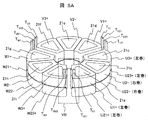
- FIG. 5A is a schematic perspective view of a stator according to the present embodiment, showing an example in which coils are connected in parallel.
- FIG. 5B is an enlarged view of a VB portion (waveline portion) shown in FIG. 5A.
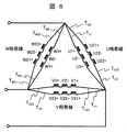
- FIG. 6 is a connection diagram of a stator winding according to the present embodiment, showing an example in which coils are connected in parallel.
- two sets of winding coils 6 are stacked and arranged in the rotational axis direction of the rotors 3 and 31.
- the winding coil 6 configured in one step (one layer) in the axial center direction of the output shaft 4 is configured in two steps (two layers).
- FIG. 5A two sets of winding coils 6 are connected in parallel.
- the winding is axially stacked, for example, in two stages, and each terminal portion (T U1 , T U21 and T W3 ) of the lead wire of each winding coil (U1 + to W3 +),
- T W23 and T U3 , T U23 and T V1 , T V21 and T V3 , T V23 and T W1 , T W22 By connecting T W23 and T U3 , T U23 and T V1 , T V21 and T V3 , T V23 and T W1 , T W22 ), the U-phase winding U1 + is formed as shown in the connection diagram of FIG.
- the conductor diameter of the winding coil 6 per wire can be reduced (for example, ⁇ 2 ⁇ ⁇ 1.4) because two parallel circuits of each phase are provided. Therefore, the winding operation can be further facilitated, and the space factor between the cores (21a to 21i) of the winding coil 6 can be increased to make the motor smaller and lighter, and highly efficient.
- the lead wire length in the configuration in which the winding coils 6 are arranged in multiple stages will be described.
- the length of the lead wire of the nth stage Ln where the length of the lead wire of the first stage is Lh and the axial length of the winding coil 6 of one stage is Lci
- Ln Lh + (n-1) ⁇ Lci (where n is a positive integer in the number of stages of the stator).
- the core on which the first stage winding coil 6 is wound and the core on which the second stage winding coil 6 is wound are integrated, but the core is divided for each stage. May be In this case, the axial length Lci of the winding coil 6 used in the above equation may be the axial length Lco of the one-step core.
- the wiring of the terminal portions (T U1 to T W3 and T U21 to T W23 ) of the lead line is formed on one gap surface side. And at the outside of the winding coil 6. For this reason, motor damage due to a short circuit between winding coils (U and V phases, V and W phases, W and U phases) is eliminated, and a highly reliable motor can be provided. Furthermore, it is good to laminate the stator coil 6 of each stage via insulating paper. In this case, since the molding pressure in the axial direction can be increased with respect to the laminated stator coils 6 at the time of molding or the like, the space factor can be further improved.
- the number of coils is nine (9 slots) and the number of permanent magnet poles of the permanent magnet rotor is eight.
- the same is true even if the number of permanent magnet poles is ten. An effect is obtained.
- the cogging torque generated by the repulsive attraction between the core and the permanent magnet can be further reduced, and the motor and the system incorporating the motor can be reduced in vibration and noise.
- the number of slots is not limited to nine, and may be a configuration provided with a multiple of nine slots.
- the rectangular wire is used in the present embodiment, the same effect can be obtained by using a round wire.
- the core material is not disclosed in the present embodiment, but is not particularly limited, and it is possible to use properly according to the specifications of the motor such as electromagnetic steel sheet, dust core, amorphous, etc.
- the present invention is not limited to the above-described embodiments, but includes various modifications.
- the embodiments described above are described in detail in order to explain the present invention in an easy-to-understand manner, and are not necessarily limited to those having all the configurations.
- SYMBOLS 1 Axial gap type motor, 2 ... Stator, 21a-21i ... Core, 221, 222 ... Bearing, 3, 31 ... Permanent magnet rotor, 4 ... Output shaft, 5 ... Housing, 6 ... Winding coil, 6a ... Wire-like grooves, 6j ... crossovers, U (U1 +, U2-, U3 +, U1-, U3-, U21 +, U22-, U23 +) ...
- V V1 +, V2-, V3 +, V21 + , V22-, V23 +
- W W1 +, W2-, W3 +, W21 +, W22-, W23 +
- T T U1 to T W3 and T U21 to T W23 ) ... Terminal part of the lead wire.
Landscapes
- Engineering & Computer Science (AREA)
- Power Engineering (AREA)
- Manufacturing & Machinery (AREA)
- Windings For Motors And Generators (AREA)
- Iron Core Of Rotating Electric Machines (AREA)
- Manufacture Of Motors, Generators (AREA)
- Permanent Magnet Type Synchronous Machine (AREA)
Abstract
本発明の目的は、連続巻きしたコイルをアキシャルギャップ型モータの固定子コイルとして容易に組み立てることができ、かつ、ギャップ面に渡り線のない巻線作業性の向上が可能なアキシャルギャップ型モータを提供することにある。回転軸方向に対向する固定子と回転子とを備え、固定子がコア21a~21i及び前記コアに巻回された巻線コイル(U1+~W3+)を周方向に複数配置した構成を有するアキシャルギャップ型モータにおいて、周方向に隣り合って順番に並ぶ第1、第2及び第3のコア21a~21cのそれぞれに、1本の連続した導線で第1、第2及び第3の巻線コイルU1+,U2-,U3+が巻回され、中央に位置する第2のコア21bに巻回された第2の巻線コイルU2-の巻き方向と、第2のコア21bの両隣りに位置する第1及び第3のコア21a,21cに巻回された第1及び第3の巻線コイルU1+,U3+の巻き方向とを、逆方向にする。
Description
本発明は、アキシャルギャップ型モータに係り、特に、回転子と固定子のスロットコンビネーションが8極9コア(スロット)のように、コア(スロット)数が9の倍数で構成されるアキシャルギャップ型モータに好適な巻線技術に関する。
近年、地球温暖化が深刻化する中で、電気機器に対する省エネルギー化の要求が高まっている。現在、国内の年間消費電力量の約55%がモータによって消費されているため、モータの高効率化に対する注目度は高い。これまでモータの高効率化には、高いエネルギー積を有する希土類磁石を用いた設計が採用されている。しかし、希土類磁石の原料であるネオジウムやディスプロシウムは、近年価格が高騰している。このため、希土類磁石を使わず、フェライト磁石のみでモータの高効率化を実現できるアキシャルギャップ型モータが注目されている。アキシャルギャップ型モータでは、ラジアルギャップ型モータよりも磁石面積を広くとることができ、フェライト磁石による保持力の低下を補うことができる。一般的に、アキシャルギャップ型モータは、複数のコアを有し、そのコアの周囲に巻線が巻回されて構成された固定子と、その軸方向両面に2つの回転子を有する構成となっている。
本技術分野の背景技術として、特開昭46-7928号公報(特許文献1)がある。この公報には、ポールピースに巻回された巻線を有し、交流を通電するようになされたそれらの巻線が、磁気的に軟質のフェライト材料でもって形成されたポールピースに巻回せしめられていることを特徴としている(特許請求の範囲参照)。また、本技術分野の背景技術として、特開2012-50250号公報(特許文献2)がある。この公報には、回転電機を組立てるときの、ステータコアの高精度位置決めと、製造工程の簡易化とを目的として、筒形状の中心部に第1の空間と、中心から等距離の円周上に複数の第2の空間とを備える収納枠体と、第1の空間に回転可能に設けられたシャフトと、第2の空間に配置されたコア及びコアに巻回されたコイルと、シャフトに固定されコアに対向する円周方向位置に複数の磁石が配置されたロータヨークと、シャフトが挿通された孔を有し収納枠体とロータヨークとを収納するケースとから構成されたアキシャルギャップ型回転電機が記載されている(要約参照)。
特許文献1では、ポールピース8個、回転子の磁極数8極で構成されたアキシャルギャップ構造の単相同期発電機が開示されている。この単相同期発電機では、巻線は、ポールピースと回転子の磁極数が同じであることから、回転子の磁極(N極S極)に対応して、正方向、逆方向、正方向、逆方向・・・と連続に巻かれているものと推察される。特許文献2では、コア数9個、回転子の磁極数8極のアキシャルギャップ回転電機が開示されているが、コイル巻線のスター結線、デルタ結線などの巻線方法に関しては開示されていない。一般的にモータの製造工程には、巻線の渡り線や中性点接続などの配線作業がある。
特に、アキシャルギャップ型モータでは、固定子コアと永久磁石とのギャップ面に渡り線などの配線があると、回転子の面ブレや異物混入などによる配線の損傷に配慮する必要がある。また、配線の損傷に配慮して固定子コアと永久磁石とのギャップ長を大きくするとモータの性能が著しく低下する。一方、配線のために固定子外径を大きくするとモータが大型化する。
特に、アキシャルギャップ型モータでは、固定子コアと永久磁石とのギャップ面に渡り線などの配線があると、回転子の面ブレや異物混入などによる配線の損傷に配慮する必要がある。また、配線の損傷に配慮して固定子コアと永久磁石とのギャップ長を大きくするとモータの性能が著しく低下する。一方、配線のために固定子外径を大きくするとモータが大型化する。
そこで、本発明の目的は、連続巻きしたコイルをアキシャルギャップ型モータの固定子コイルとして容易に組み立てることができ、かつ、ギャップ面に渡り線のない巻線作業性の向上が可能なアキシャルギャップ型モータを提供することにある。
本発明のアキシャルギャップ型モータは、例えば8極9スロット(コア)のスロットコンビネーションのように、スロット(コア)数が9の倍数で構成されたアキシャルギャップ型モータにおいて、1相分のコアを3個ひと組として構成し、かつ、巻線コイルを1本の導線で3個連続に巻回する。
本発明によれば、連続巻きした巻線コイルによりアキシャルギャップ型モータの固定子コイルとして容易に組み立てることができ、かつ、渡り線をコア間に配置して固定子コアと永久磁石とのギャップ面に渡り線のないアキシャルギャップ型モータを提供でき、巻線作業性の向上が可能になる。
上記した以外の課題、構成及び効果は、以下の実施形態の説明により明らかにされる。
以下、本発明の実施例について図面を用いて説明する。
図1乃至図4Cを参照して、本発明に係る第一実施例について説明する。図1は本実施例に係るアキシャルギャップ型モータ1の断面図である。図2は本実施例に係る固定子2の斜視図である。図3は、本実施例に係る固定子巻線の結線図である。図4は本実施例に係る1相分のコイルの組立手順の説明図であり、図4Aはその第一手順を示す図、図4Bはその第二手順を示す図、図4Cはその第三手順を示す図である。
このアキシャルギャップ型モータ1は、偏平な円筒形状に形成された固定子2と、固定子2の軸方向両面に所定の空隙(ギャップ)を隔てて対向配置される一対の永久磁石回転子3、31とを備えている。永久磁石回転子3、31は、回転駆動力を出力する出力軸4に固定されている。なお、固定子2および永久磁石回転子3、31はハウジング5内に収納される。
本実施例において、永久磁石回転子3、31は固定子2を挟んで軸方向両面に配置されているが、いずれか一方のみであっても良く、本実施例において永久磁石回転子の構成はアキシャルギャップ型モータ1を構成するのに必要な機能を備えていれば良い。図2に示すように、固定子2には出力軸となる回転軸4を中心軸として円周方向に複数個のコア21(21a~21i)が配置されている。コア21(21a~21i)の外周には巻線コイル6(U1+、U2-、U3+、V1+、V2-、V3+、W1+、W2-、W3+)が巻回されている。
コア21aには巻線コイルU1+が巻回され、コア21bには巻線コイルU2-が巻回され、コア21cには巻線コイルU3+が巻回され、コア21dには巻線コイルV1+が巻回され、コア21eには巻線コイルV2-が巻回され、コア21fには巻線コイルV3+が巻回され、コア21gには巻線コイルW1+が巻回され、コア21hには巻線コイルW2-が巻回され、コア21iには巻線コイルW3+が巻回されている。すなわち、本実施例では、コアが9個で構成された9スロットの構成を採用しており、巻線コイルはU、V及びWの各相に3個ずつ配設されている。
固定子2の中心部には一対のベアリング221、222が配置されている。この例において、ベアリング221、222はボールベアリングで構成しており、その内輪は出力軸4に挿入され、外輪はベアリングホルダ24に挿入されている。本実施例においてベアリング221、222の構成は、ボールベアリングに限定するものではなく、ころがり軸受、すべり軸受などのボールベアリング以外のベアリングを採用してもよい。またその個数も2個に限定するものではない。
図1、図2によって本実施例の要部の説明を行う。アキシャルギャップ型モータ1の固定子2のコア(スロット)21a~21iの外周には、それぞれU相巻線(U1+、U2-、U3+)、V相巻線(V1+、V2-、V3+)、W相巻線(W1+、W2-、W3+)が巻回され、コア21a~21iが固定子2の周方向に配列されている。
図2の9個の巻線コイル6(U1+、U2-、U3+、V1+、V2-、V3+、W1+、W2-、W3+)の接続法は、例えば、図3に示したデルタ結線にできる。自動車用の永久磁石回転電機では、駆動電源がバッテリであるために、12Vと低い。従ってスター結線に比較してデルタ結線では巻線コイル6の端子電圧を√3倍に増加させることができる。それによって同一出力では相電流を小さくできるために巻線コイル6の径を小さくすることができる。
前記のデルタ結線の実施例では、巻線作業をし易くすることができ、コア間における巻線コイル6の占積率を向上させることができる。これによって高効率のアキシャルギャップ型モータ1を提供できる。
前記のデルタ結線の実施例では、巻線作業をし易くすることができ、コア間における巻線コイル6の占積率を向上させることができる。これによって高効率のアキシャルギャップ型モータ1を提供できる。
図2および図3に示す形態を成す固定子の巻線作業は、U相巻線(U3+、U2-、U1+)、V相巻線(V3+、V2-、V1+)、W相巻線(W3+、W2-、W1+)の相ごとに巻回し、各相を構成する3つの巻線を1本の線によって図4A乃至図4Cに示すように連続的に巻回することによって実施される。ここで、アキシャルギャップ型モータ1の引き出し線部であるTW3、TU1、TU3、TV1、TV3、TW1は図示のように形成されて外部との接続を容易にすることができる。すなわち、引き出し線部であるTW3とTU1、TU3とTV1、TV3とTW1を圧着等により接続し、例えば3相ブラシレスモータのようにU相、V相、W相として外部へ引き出し、モータ駆動のためのインバータ(図示せず)との接続用配線として使用できる。
以上の構成によれば、すべての巻線コイル6の接続は隣り合う巻線間の接続のみで済むために引き出し線を短くできる。また、各コア(21a~21i)の巻線コイル6をすべて切り離して接続すると1相当たり6カ所で、3相では18カ所となるのに対して、本実施例では、TW3とTU1間、TU3とTV1間、TV3とTW1間の計3カ所の接続で済み、接続箇所を大幅に低減でき、電工作業(巻線コイルの接続作業)を大幅に低減することができる。
これは、接続部に起因する抵抗損失を大幅に低減することができて効率向上につながる。
ここで、各相巻線に示している+および-の符号は、-を右巻きとしたとき、+は-とは逆巻の左巻きに導線を巻回していることを示している。-を左巻きとしたとき、+は-とは逆巻の右巻きに導線を巻回していることを示す。以下、+を右巻き、-を左巻きとして説明する。なお、右巻きを正方向巻きとした場合、左巻きは逆方向巻きであり、左巻きを正方向巻きとした場合、右巻きは逆方向巻きである。-と+とは巻き方向の正逆の関係を示すものであり、-と+とを正逆いずれの方向に定義しても構わない。
これは、接続部に起因する抵抗損失を大幅に低減することができて効率向上につながる。
ここで、各相巻線に示している+および-の符号は、-を右巻きとしたとき、+は-とは逆巻の左巻きに導線を巻回していることを示している。-を左巻きとしたとき、+は-とは逆巻の右巻きに導線を巻回していることを示す。以下、+を右巻き、-を左巻きとして説明する。なお、右巻きを正方向巻きとした場合、左巻きは逆方向巻きであり、左巻きを正方向巻きとした場合、右巻きは逆方向巻きである。-と+とは巻き方向の正逆の関係を示すものであり、-と+とを正逆いずれの方向に定義しても構わない。
次に、巻線コイル6の組み立て方法について説明する。図2において、コア21a~21cに巻回されたU相巻線(U1+、U2-、U3+)とコア21d~21fに巻回されたV相巻線(V1+、V2-、V3+)とコア21g~21iに巻回されたW相巻線(W1+、W2-、W3+)とは同一構成のため、ここではコア21a~21cに巻回されたU相巻線(U1+、U2-、U3+)を例にとって説明する。
本実施例における巻線方法では、コア21a、21b、21cに巻回されているU相巻線U1+、U2-、U3+を1本の導線で連続して巻回する。すなわち、U1+、U2-、U3+の巻線を、1本の導線で連続に同一軸方向でかつ同一周回方向に巻回する巻線治具(図示せず)により、巻線U3-、U2-、U1-の順に巻回する。巻回した巻線を巻線治具から取り外した状態について図4Aに示す。なお、巻線の巻き方向(左巻き、右巻き)は、図4A上で、正面(U1-側)から見たときの巻き方向で説明する。この状態では、巻線U1-、巻線U2-、巻線U3-の順に直線状に並んでいる。この状態では、巻線U1-、U2-及びU3-はいずれも左巻きの状態で、巻き方向は同一である。図中に示す矢印は巻き方向を示す。
本実施例では、巻線U1-、U2-及びU3-はいずれもコア21a~21cの外周に二重に巻回されている。巻線U3-を二重に巻回する際は、巻き始めから巻軸方向に沿って巻回していくことにより内周側の巻線を巻回し、内周側の巻線を巻回し終わると巻軸方向に沿って内周側の巻線を巻回する時とは逆方向に巻回していくことにより外周側の巻線を巻回する。本実施例では、内周側の巻線を図4Aの奥側から手前側に巻き、手前側で折り返して奥側へ向かって巻いて行く。外周側の巻線を巻回し終わると、渡り線6jとなる部分を設けて巻線U2-を巻線U3-と同様に巻回し、続いてU1-を巻線U3-と同様に巻回する。このとき、巻線U1-と巻線U2-との間で渡り線6jとなる部分と、巻線U2-と巻線U3-との間で渡り線6jとなる部分とは、巻線U1-、U2-及びU3-を挟んで両側(図4BのL面側とR面側)に分かれて位置するように巻回する。
渡り線6jを図2のように配置するためには、巻線U1-、U2-及びU3-は偶数回の重ね巻きにすると良い。なお、本実施例においては、二重(二層)の重ね巻きにしている。
次に、図4B及び図4Cに示すように、真ん中の巻線U2-を基準として、一方の巻線U1-を、R面を基準にして180°反転させることにより、巻線U2-の右側面に配置して巻線U1+とする。このとき、巻線U1は軸方向における上下が入れ替わり、巻線U1は左巻きの巻線U1-から右巻きの巻線U1+に変わる。次に、巻線U2-を基準として、他方の巻線U3-を巻線U2-のL面を基準に180°反転させて巻線U2-の左側面に配置する。このとき、巻線U3は軸方向における上下が入れ替わり、巻線U3は左巻きの巻線U3-から右巻きの巻線U3+に変わる。これにより、図4Cに示すように、U相巻線U1+、U2-、U3+が同一平面上で円周状に配置される。
図4A、図4B及び図4Cで説明した巻線方法によれば、第1の巻線コイルである巻線U1+の一方の巻線端部は引き出し線TU1として引き出される。巻線U1+の他方の巻線端部は第1の渡り線6jを経て第2の巻線コイルである巻線U2-の一方の巻線端部となる。巻線U2-の他方の巻線端部は第2の渡り線6jを経て第3の巻線コイルである巻線U3+一方の巻線端部となる。巻線U3+の他方の巻線端部は引き出し線TU3として引き出される。巻線U1+の一方の巻線端部と巻線U3+の他方の巻線端部とは回転軸方向の同じ側に位置する。巻線U2-の一方の巻線端部と他方の巻線端部とは、回転軸方向の同じ側に位置し、且つ巻線U1+の一方の巻線端部及び巻線U3+の他方の巻線端部に対して回転軸方向の反対側に位置する。
次に、他の相(V相およびW相)も同様の行程を繰り返して、残りのV相、W相の各巻線コイルV1+、V2-、V3+とW1+、W2-、W3+とをそれぞれ配置し、各巻線コイル(U1+~W3+)にコア21a~21iを挿入することで、巻線コイル6が巻回されたコア21a~21iを有するアキシャルギャップ型モータの固定子2が完成する。なお、前記巻線コイル6とコア21a~21iとは樹脂モールドなどにより一体化されている。
本実施例では、同一軸方向で、かつ、同一周回方向に巻線コイル6を巻回することによって、巻線コイル6の製作精度、作業性は向上する。さらに、渡り線6jを各相の巻線コイル(U相巻線U1+、U2-、U3+とV相巻線V1+、V2-、V3+およびV相巻線V1+、V2-、V3+とW相巻線W1+、W2-、W3+およびW相巻線W1+、W2-、W3+とU相巻線U1+、U2-、U3+)間に配置することができるため、固定子2のギャップ面側に渡り線をなくすることができる。このため、回転子の面ブレや異物混入などによる渡り線の損傷をなくすことができ、信頼性の高いモータとすることができる。
また、隣り合う2つのコアに巻回された巻線コイル6同士の間には、外周側のコイル巻線6の曲がり部に回転軸方向に伸びる筋状の溝6a(図2参照)が形成される。この溝6aに渡り線6jが配置されることにより、径方向寸法の拡大も抑制することができる。
図5A,図5B及び図6を参照して、本発明に係る第二実施例について説明する。図5Aは、本実施例に関わる固定子の概略的な斜視図であり、コイルを並列接続した例を示す図である。図5Bは、図5Aに示すVB部(波線部)の拡大図である。図6は、本実施例に関わる固定子巻線の結線図であり、コイルを並列接続した例を示す図である。
本実施例では、二組の巻線コイル6を回転子3,31の回転軸方向に積層して配置している。図1のアキシャルギャップ型モータの断面図において、出力軸4の軸心方向に一段(一層)に構成された巻線コイル6が二段(二層)に構成されていると考えればよい。
本実施例では、図5Aに示すように、二組の巻線コイル6を並列接続する。図5A及び図5Bにおいて、前記の巻線を軸方向に、例えば、2段に積層して、各巻線コイル(U1+~W3+)の引き出し線の各端子部(TU1、TU21とTW3、TW23およびTU3、TU23とTV1、TV21およびTV3、TV23とTW1、TW22)を接続することで、各相とも図6の接続図で示すようにU相巻線U1+、U21+とW相巻線W3+、W23+およびU相巻線U3+、U23+とV相巻線V1+、V21+およびV相巻線V3+、V23+とW相巻線W1+、W21+をそれぞれ簡単に並列接続することができる。この場合、2段目の巻線コイル6の引き出し線を1段目の引き出し線と同じ高さになるように、2段目の引き出しの長さを長めにして、固定子2の一方のギャップ面側で接続できるようにすると良い。
本実施例の構成では、各相2つの並列回路を有するために1本あたりの巻線コイル6の導体径を下げることができる(例えばφ2→φ1.4)。従って巻線作業を更に容易にすることができるとともに、巻線コイル6のコア(21a~21i)間における占積率を高め、より小型軽量で、高効率のモータとすることができる。
ここで、巻線コイル6が多段に配置された構成における引き出し線長さについて説明する。巻線コイル6が多段に配置された構成では、1段目の引き出し線長さをLh、一段の巻線コイル6の軸方向長さをLciとしたとき、n段目の引き出し線長さLnを、概ね、Ln=Lh+(n-1)×Lci(但し、nは固定子の段数で正の整数)とするとよい。
例えば、各段の引き出し線長さを全て同じ長さとすると巻線コイル(U相とV相、V相とW相、W相とU相)間のデルタ結線や引き出し線の配線が巻線コイル間で行われることになり、複雑な配線作業や絶縁処理が発生する。また、巻線コイル間での短絡などによるモータ損傷が発生する危険性が高まる。なお、本実施例では、1段目の巻線コイル6が巻回されるコアと2段目の巻線コイル6が巻回されるコアとを一体としたが、一段毎にコアを分割してもよい。この場合、上式で用いた巻線コイル6の軸方向長さLciは、一段のコアにおける軸方向長さLcoとしてもよい。
例えば、各段の引き出し線長さを全て同じ長さとすると巻線コイル(U相とV相、V相とW相、W相とU相)間のデルタ結線や引き出し線の配線が巻線コイル間で行われることになり、複雑な配線作業や絶縁処理が発生する。また、巻線コイル間での短絡などによるモータ損傷が発生する危険性が高まる。なお、本実施例では、1段目の巻線コイル6が巻回されるコアと2段目の巻線コイル6が巻回されるコアとを一体としたが、一段毎にコアを分割してもよい。この場合、上式で用いた巻線コイル6の軸方向長さLciは、一段のコアにおける軸方向長さLcoとしてもよい。
本実施例では、n段目の引き出し線長さLnを上述したように設定することにより、引き出し線の端子部(TU1~TW3およびTU21~TW23)の配線を一方のギャップ面側で、かつ巻線コイル6の外側で実施できる。このため、巻線コイル(U相とV相、V相とW相、W相とU相)間での短絡等によるモータ損傷が無くなり、信頼性の高いモータを提供できる。さらには、各段の固定子コイル6を、絶縁紙を介して積層するとよい。この場合、モールド成型時等で、積層した固定子コイル6に対して軸方向の成形圧力を高めることができるので、より占積率を向上させることが可能となる。
以上の実施例では、コイル数が9個配置(9スロット)で、永久磁石回転子の永久磁石磁極数は8極とした例を示しているが、永久磁石磁極数を10極としても同様の効果が得られる。この場合、コアと永久磁石間の反発吸引力で発生するコギングトルクの更なる低減が可能となり、モータおよびモータを組み込んだシステムの振動、騒音低減ができる。
また、スロット数は9スロットに限らず、9の倍数個のスロットを備えた構成であれば良い。
また、スロット数は9スロットに限らず、9の倍数個のスロットを備えた構成であれば良い。
本実施例では平角線を用いているが、丸線を用いても同様の効果が得られる。また、コア材料については本実施例の中では開示していないが、特に限定するものではなく、電磁鋼板、圧粉磁心、アモルファスなどモータの仕様などによって任意に使い分けることは可能である。
なお、本発明は上記した各実施例に限定されるものではなく、様々な変形例が含まれる。例えば、上記した実施例は本発明を分かりやすく説明するために詳細に説明したものであり、必ずしも全ての構成を備えるものに限定されるものではない。また、各実施例の構成の一部について、他の構成の追加・削除・置換をすることが可能である。
1…アキシャルギャップ型モータ、2…固定子、21a~21i…コア、221,222…ベアリング、3、31…永久磁石回転子、4…出力軸、5…ハウジング、6…巻線コイル、6a…筋状の溝、6j…渡り線、U(U1+,U2-,U3+,U1-,U3-,U21+,U22-,U23+)…複数のU相巻線、V(V1+,V2-,V3+,V21+,V22-,V23+)…複数のV相巻線、W(W1+,W2-,W3+,W21+,W22-,W23+)…複数のW相巻線、T(TU1~TW3及びTU21~TW23)…引き出し線の端子部。
Claims (11)
- 回転軸方向に対向する固定子と回転子とを備え、前記固定子がコア及び前記コアに巻回された巻線コイルを周方向に複数配置した構成を有するアキシャルギャップ型モータにおいて、
周方向に隣り合って順番に並ぶ第1、第2及び第3のコアのそれぞれに、1本の連続した導線で第1、第2及び第3の巻線コイルが巻回され、中央に位置する第2のコアに巻回された第2の巻線コイルの巻き方向と、前記第2のコアの両隣りに位置する第1及び第3のコアに巻回された第1及び第3の巻線コイルの巻き方向とが逆方向であることを特徴とするアキシャルギャップ型モータ。 - 請求項1に記載のアキシャルギャップ型モータにおいて、
前記固定子に配置されるコア数が9の倍数個であり、
前記第1の巻線コイルの一方の巻線端部は引き出し線として引き出され、
前記第1の巻線コイルの他方の巻線端部は第1の渡り線を経て前記第2の巻線コイルの一方の巻線端部となり、
前記第2の巻線コイルの他方の巻線端部は第2の渡り線を経て前記第3の巻線コイルの一方の巻線端部となり、
前記第3の巻線コイルの他方の巻線端部は引き出し線として引き出され、
前記第1の巻線コイルの一方の巻線端部と前記第3の巻線コイルの他方の巻線端部とが回転軸方向の同じ側に位置し、
前記第2の巻線コイルの一方の巻線端部と他方の巻線端部とは、回転軸方向の同じ側に位置し、且つ前記第1の巻線コイルの一方の巻線端部及び前記第3の巻線コイルの他方の巻線端部と回転軸方向の反対側に位置することを特徴とするアキシャルギャップ型モータ。 - 請求項2に記載のアキシャルギャップ型モータにおいて、
前記第1の渡り線及び前記第2の渡り線が回転軸方向における巻線コイルの巻回範囲の内側に位置することを特徴とするアキシャルギャップ型モータ。 - 請求項3に記載のアキシャルギャップ型モータにおいて、
固定子を構成するコアを9極、回転子を構成する磁極数を8極としたことを特徴とするアキシャルギャップ型モータ。 - 請求項4に記載のアキシャルギャップ型モータにおいて、
前記第1の巻線コイル、前記第2の巻線コイル及び前記第3の巻線コイルを3組備え、各組がU相、V相及びW相の各相を構成することを特徴とするアキシャルギャップ型モータ。 - 請求項5に記載のアキシャルギャップ型モータにおいて、
9極分の前記コアと前記巻線コイルとは周方向に配置された状態で樹脂モールドにより一体化されていることを特徴とするアキシャルギャップ型モータ。 - 請求項3に記載のアキシャルギャップ型モータにおいて、
固定子を構成するコアを9極、回転子を構成する磁極数を10極としたことを特徴とするアキシャルギャップ型モータ。 - 請求項4又は7に記載のアキシャルギャップ型モータにおいて、
前記巻線コイルはデルタ結線されたことを特徴とするアキシャルギャップ型モータ。 - 請求項1に記載のアキシャルギャップ型モータにおいて、
前記巻線コイルの軸方向長さをLm、コアの軸方向長さをLcoとしたとき、Lm≦Lcoとしたことを特徴とするアキシャルギャップ型モータ。 - 請求項1に記載のアキシャルギャップ型モータにおいて、
前記固定子を軸方向に多段に配置し、各段の巻線コイルを並列接続したことを特徴とするアキシャルギャップ型モータ。 - 請求項10に記載のアキシャルギャップ型モータにおいて、
1段目の引き出し線長さをLh、コアの軸方向長さをLcoとしたとき、各段の引き出し線長さLnを、Ln=Lh+(n-1)×Lco(但し、nは固定子の段数で正の整数)としたことを特徴とするアキシャルギャップ型モータ。
Priority Applications (3)
| Application Number | Priority Date | Filing Date | Title |
|---|---|---|---|
| CN201480072812.5A CN105900315A (zh) | 2014-01-10 | 2014-11-10 | 轴向间隙型马达 |
| US15/104,558 US20160315510A1 (en) | 2014-01-10 | 2014-11-10 | Axial Gap Type Motor |
| DE112014005587.5T DE112014005587T5 (de) | 2014-01-10 | 2014-11-10 | Motor vom Typ mit Axialspalt |
Applications Claiming Priority (2)
| Application Number | Priority Date | Filing Date | Title |
|---|---|---|---|
| JP2014002933A JP6223835B2 (ja) | 2014-01-10 | 2014-01-10 | アキシャルギャップ型モータ |
| JP2014-002933 | 2014-01-10 |
Publications (1)
| Publication Number | Publication Date |
|---|---|
| WO2015104893A1 true WO2015104893A1 (ja) | 2015-07-16 |
Family
ID=53523734
Family Applications (1)
| Application Number | Title | Priority Date | Filing Date |
|---|---|---|---|
| PCT/JP2014/079701 Ceased WO2015104893A1 (ja) | 2014-01-10 | 2014-11-10 | アキシャルギャップ型モータ |
Country Status (5)
| Country | Link |
|---|---|
| US (1) | US20160315510A1 (ja) |
| JP (1) | JP6223835B2 (ja) |
| CN (1) | CN105900315A (ja) |
| DE (1) | DE112014005587T5 (ja) |
| WO (1) | WO2015104893A1 (ja) |
Cited By (1)
| Publication number | Priority date | Publication date | Assignee | Title |
|---|---|---|---|---|
| US11121596B2 (en) | 2016-02-29 | 2021-09-14 | Denso Corporation | Stator of brushless motor, brushless motor, and method of manufacturing stator of brushless motor |
Families Citing this family (27)
| Publication number | Priority date | Publication date | Assignee | Title |
|---|---|---|---|---|
| US11139707B2 (en) | 2015-08-11 | 2021-10-05 | Genesis Robotics And Motion Technologies Canada, Ulc | Axial gap electric machine with permanent magnets arranged between posts |
| US9742225B2 (en) | 2015-08-11 | 2017-08-22 | Genesis Robotics Llp | Electric machine |
| JP6798231B2 (ja) * | 2016-02-29 | 2020-12-09 | 株式会社デンソー | ブラシレスモータのステータ及びブラシレスモータ |
| WO2017150312A1 (ja) * | 2016-02-29 | 2017-09-08 | アスモ 株式会社 | ブラシレスモータのステータ、ブラシレスモータ及びブラシレスモータのステータの製造方法 |
| US11043885B2 (en) | 2016-07-15 | 2021-06-22 | Genesis Robotics And Motion Technologies Canada, Ulc | Rotary actuator |
| US10256682B2 (en) * | 2016-09-28 | 2019-04-09 | Emerson Electric Co. | Stator assemblies for three phase dynamoelectric machines and related winding methods |
| JP6954581B2 (ja) * | 2016-11-11 | 2021-10-27 | 株式会社プロスパイン | 回転増速部を有する発電機 |
| US10135310B2 (en) * | 2017-01-11 | 2018-11-20 | Infinitum Electric Inc. | System and apparatus for modular axial field rotary energy device |
| EP3637584A4 (en) * | 2017-05-31 | 2020-05-27 | Guangdong Meizhi Compressor Co., Ltd. | MOTOR STATOR FOR USE IN THE COMPRESSOR, PERMANENT MAGNETIC MOTOR AND COMPRESSOR |
| CN108092435A (zh) * | 2018-01-10 | 2018-05-29 | 上海硅泰电子有限公司 | 定子铁芯绕组单元、定子组件以及盘式电机 |
| WO2019190959A1 (en) | 2018-03-26 | 2019-10-03 | Infinitum Electric Inc. | System and apparatus for axial field rotary energy device |
| JP6671447B1 (ja) * | 2018-11-28 | 2020-03-25 | 三菱電機株式会社 | 回転電機およびその製造方法 |
| GB2580918B (en) * | 2019-01-29 | 2021-07-07 | Saietta Group Ltd | Axial flux electrical machine |
| CN209329821U (zh) | 2019-02-01 | 2019-08-30 | 上海磁雷革传动系统有限公司 | 一种定子绕组、定子和电机 |
| DE102019216860A1 (de) * | 2019-10-31 | 2021-05-06 | Robert Bosch Gmbh | Axialflussmaschine für ein elektrisches Bearbeitungsgerät sowie elektrisches Bearbeitungsgerät mit einer Axialflussmaschine |
| US11283319B2 (en) | 2019-11-11 | 2022-03-22 | Infinitum Electric, Inc. | Axial field rotary energy device with PCB stator having interleaved PCBS |
| US20210218304A1 (en) | 2020-01-14 | 2021-07-15 | Infinitum Electric, Inc. | Axial field rotary energy device having pcb stator and variable frequency drive |
| JP7468153B2 (ja) * | 2020-05-28 | 2024-04-16 | 株式会社デンソー | モータ |
| AU2020483987B2 (en) * | 2020-12-31 | 2024-06-06 | Renwei YU | Disc-type motor stator and winding method therefor |
| US20240146134A1 (en) * | 2021-04-10 | 2024-05-02 | Schaeffler Technologies AG & Co. KG | Stator of an electric flux machine, and axial flux machine |
| US11482908B1 (en) | 2021-04-12 | 2022-10-25 | Infinitum Electric, Inc. | System, method and apparatus for direct liquid-cooled axial flux electric machine with PCB stator |
| CN113364162B (zh) * | 2021-06-21 | 2022-04-15 | 湖州小为科技有限公司 | 一种定子结构、转子结构、超薄电机以及定子成型工艺 |
| EP4412048A4 (en) * | 2021-09-27 | 2025-01-15 | Denso Corporation | ELECTRIC LATHE |
| JP2023147429A (ja) * | 2022-03-30 | 2023-10-13 | 株式会社アスター | コイルユニットの製造方法 |
| JP2024033621A (ja) * | 2022-08-30 | 2024-03-13 | 株式会社デンソー | 回転電機 |
| DE102023113748A1 (de) * | 2023-05-25 | 2024-11-28 | Schaeffler Technologies AG & Co. KG | Stator mit einem eine Wicklung eines Statorzahns umspannendem Fixierelement und Axialflussmaschine |
| DE102023117311A1 (de) * | 2023-06-30 | 2025-01-02 | Schaeffler Technologies AG & Co. KG | Stator einer elektrischen Rotationsmaschine, Statoranordnung und elektrische Rotationsmaschine |
Citations (4)
| Publication number | Priority date | Publication date | Assignee | Title |
|---|---|---|---|---|
| JP2005237086A (ja) * | 2004-02-18 | 2005-09-02 | Sumitomo Electric Ind Ltd | アキシャルモータ及びその製造方法 |
| JP2006191757A (ja) * | 2005-01-07 | 2006-07-20 | Hitachi Ltd | 回転電機及びそれを用いた電動パワーステアリング装置 |
| JP2008301652A (ja) * | 2007-06-01 | 2008-12-11 | Mitsubishi Electric Corp | 永久磁石式回転電機およびそれを用いた電動パワーステアリング装置 |
| JP2010183727A (ja) * | 2009-02-05 | 2010-08-19 | Fujitsu General Ltd | アキシャルエアギャップ型電動機 |
Family Cites Families (1)
| Publication number | Priority date | Publication date | Assignee | Title |
|---|---|---|---|---|
| JP5974592B2 (ja) * | 2012-03-31 | 2016-08-23 | 日本電産株式会社 | 電機子および電動機 |
-
2014
- 2014-01-10 JP JP2014002933A patent/JP6223835B2/ja not_active Expired - Fee Related
- 2014-11-10 DE DE112014005587.5T patent/DE112014005587T5/de not_active Withdrawn
- 2014-11-10 US US15/104,558 patent/US20160315510A1/en not_active Abandoned
- 2014-11-10 WO PCT/JP2014/079701 patent/WO2015104893A1/ja not_active Ceased
- 2014-11-10 CN CN201480072812.5A patent/CN105900315A/zh active Pending
Patent Citations (4)
| Publication number | Priority date | Publication date | Assignee | Title |
|---|---|---|---|---|
| JP2005237086A (ja) * | 2004-02-18 | 2005-09-02 | Sumitomo Electric Ind Ltd | アキシャルモータ及びその製造方法 |
| JP2006191757A (ja) * | 2005-01-07 | 2006-07-20 | Hitachi Ltd | 回転電機及びそれを用いた電動パワーステアリング装置 |
| JP2008301652A (ja) * | 2007-06-01 | 2008-12-11 | Mitsubishi Electric Corp | 永久磁石式回転電機およびそれを用いた電動パワーステアリング装置 |
| JP2010183727A (ja) * | 2009-02-05 | 2010-08-19 | Fujitsu General Ltd | アキシャルエアギャップ型電動機 |
Cited By (1)
| Publication number | Priority date | Publication date | Assignee | Title |
|---|---|---|---|---|
| US11121596B2 (en) | 2016-02-29 | 2021-09-14 | Denso Corporation | Stator of brushless motor, brushless motor, and method of manufacturing stator of brushless motor |
Also Published As
| Publication number | Publication date |
|---|---|
| DE112014005587T5 (de) | 2016-11-03 |
| JP6223835B2 (ja) | 2017-11-01 |
| CN105900315A (zh) | 2016-08-24 |
| US20160315510A1 (en) | 2016-10-27 |
| JP2015133787A (ja) | 2015-07-23 |
Similar Documents
| Publication | Publication Date | Title |
|---|---|---|
| JP6223835B2 (ja) | アキシャルギャップ型モータ | |
| JP6019234B2 (ja) | アキシャルギャップ型モータとその巻線の製造方法 | |
| JP3971692B2 (ja) | スロットレス永久磁石式回転電機及びその巻線製造方法 | |
| WO2016132450A1 (ja) | 永久磁石式三相二重化モータおよび電動パワーステアリング装置 | |
| JP4983022B2 (ja) | モータ | |
| JP5619046B2 (ja) | 回転電機およびそれに用いられるステータの製造方法 | |
| CN105406629A (zh) | 电机定子、永磁发电机 | |
| JPWO2015029579A1 (ja) | 回転電機 | |
| US20190312476A1 (en) | Motor | |
| WO2014034712A1 (ja) | 回転電機 | |
| JPWO2008087808A1 (ja) | ギャップワインディング形モータ | |
| JP5248751B2 (ja) | スロットレス永久磁石型回転電機 | |
| JP2005151785A (ja) | リング状の電機子コイルを有する同期発電機 | |
| JP4415176B2 (ja) | リング状の固定子コイルを有する誘導電動機 | |
| CN106803709B (zh) | 永磁同步电机及其装配方法 | |
| JP4482918B2 (ja) | リング状の固定子コイルを有する永久磁石型電動機 | |
| JP2003333811A (ja) | 軸方向に分割された複数の固定子巻線を有する誘導電動機 | |
| CN205178690U (zh) | 电机定子、永磁发电机 | |
| JP6190694B2 (ja) | ロータ、ステータ、及び、モータ | |
| JP2005253280A (ja) | リング状の固定子コイルを有するアウターロータ形のブラシレスdcモータ及びacサーボモータ | |
| JP7735694B2 (ja) | モータ | |
| JP2013094030A (ja) | 電機子コイル及び同期回転機 | |
| US20180034337A1 (en) | Rotary electric machine | |
| JP2017017914A (ja) | 電動モータの固定子及び電動モータ | |
| JP5931489B2 (ja) | 直流モータの巻線巻装方法、及び直流モータ |
Legal Events
| Date | Code | Title | Description |
|---|---|---|---|
| 121 | Ep: the epo has been informed by wipo that ep was designated in this application |
Ref document number: 14878332 Country of ref document: EP Kind code of ref document: A1 |
|
| WWE | Wipo information: entry into national phase |
Ref document number: 15104558 Country of ref document: US |
|
| WWE | Wipo information: entry into national phase |
Ref document number: 112014005587 Country of ref document: DE |
|
| 122 | Ep: pct application non-entry in european phase |
Ref document number: 14878332 Country of ref document: EP Kind code of ref document: A1 |