WO2015098877A1 - Spray nozzle - Google Patents
Spray nozzle Download PDFInfo
- Publication number
- WO2015098877A1 WO2015098877A1 PCT/JP2014/083976 JP2014083976W WO2015098877A1 WO 2015098877 A1 WO2015098877 A1 WO 2015098877A1 JP 2014083976 W JP2014083976 W JP 2014083976W WO 2015098877 A1 WO2015098877 A1 WO 2015098877A1
- Authority
- WO
- WIPO (PCT)
- Prior art keywords
- nozzle
- liquid
- spray nozzle
- flow path
- divided
- Prior art date
Links
Images


Classifications
-
- B—PERFORMING OPERATIONS; TRANSPORTING
- B60—VEHICLES IN GENERAL
- B60S—SERVICING, CLEANING, REPAIRING, SUPPORTING, LIFTING, OR MANOEUVRING OF VEHICLES, NOT OTHERWISE PROVIDED FOR
- B60S1/00—Cleaning of vehicles
- B60S1/02—Cleaning windscreens, windows or optical devices
- B60S1/46—Cleaning windscreens, windows or optical devices using liquid; Windscreen washers
- B60S1/48—Liquid supply therefor
- B60S1/52—Arrangement of nozzles; Liquid spreading means
-
- B—PERFORMING OPERATIONS; TRANSPORTING
- B05—SPRAYING OR ATOMISING IN GENERAL; APPLYING FLUENT MATERIALS TO SURFACES, IN GENERAL
- B05B—SPRAYING APPARATUS; ATOMISING APPARATUS; NOZZLES
- B05B1/00—Nozzles, spray heads or other outlets, with or without auxiliary devices such as valves, heating means
- B05B1/34—Nozzles, spray heads or other outlets, with or without auxiliary devices such as valves, heating means designed to influence the nature of flow of the liquid or other fluent material, e.g. to produce swirl
-
- B—PERFORMING OPERATIONS; TRANSPORTING
- B05—SPRAYING OR ATOMISING IN GENERAL; APPLYING FLUENT MATERIALS TO SURFACES, IN GENERAL
- B05B—SPRAYING APPARATUS; ATOMISING APPARATUS; NOZZLES
- B05B1/00—Nozzles, spray heads or other outlets, with or without auxiliary devices such as valves, heating means
- B05B1/02—Nozzles, spray heads or other outlets, with or without auxiliary devices such as valves, heating means designed to produce a jet, spray, or other discharge of particular shape or nature, e.g. in single drops, or having an outlet of particular shape
- B05B1/04—Nozzles, spray heads or other outlets, with or without auxiliary devices such as valves, heating means designed to produce a jet, spray, or other discharge of particular shape or nature, e.g. in single drops, or having an outlet of particular shape in flat form, e.g. fan-like, sheet-like
- B05B1/042—Outlets having two planes of symmetry perpendicular to each other, one of them defining the plane of the jet
-
- B—PERFORMING OPERATIONS; TRANSPORTING
- B05—SPRAYING OR ATOMISING IN GENERAL; APPLYING FLUENT MATERIALS TO SURFACES, IN GENERAL
- B05B—SPRAYING APPARATUS; ATOMISING APPARATUS; NOZZLES
- B05B1/00—Nozzles, spray heads or other outlets, with or without auxiliary devices such as valves, heating means
- B05B1/02—Nozzles, spray heads or other outlets, with or without auxiliary devices such as valves, heating means designed to produce a jet, spray, or other discharge of particular shape or nature, e.g. in single drops, or having an outlet of particular shape
- B05B1/10—Nozzles, spray heads or other outlets, with or without auxiliary devices such as valves, heating means designed to produce a jet, spray, or other discharge of particular shape or nature, e.g. in single drops, or having an outlet of particular shape in the form of a fine jet, e.g. for use in wind-screen washers
-
- B—PERFORMING OPERATIONS; TRANSPORTING
- B05—SPRAYING OR ATOMISING IN GENERAL; APPLYING FLUENT MATERIALS TO SURFACES, IN GENERAL
- B05B—SPRAYING APPARATUS; ATOMISING APPARATUS; NOZZLES
- B05B1/00—Nozzles, spray heads or other outlets, with or without auxiliary devices such as valves, heating means
- B05B1/34—Nozzles, spray heads or other outlets, with or without auxiliary devices such as valves, heating means designed to influence the nature of flow of the liquid or other fluent material, e.g. to produce swirl
- B05B1/3405—Nozzles, spray heads or other outlets, with or without auxiliary devices such as valves, heating means designed to influence the nature of flow of the liquid or other fluent material, e.g. to produce swirl to produce swirl
- B05B1/341—Nozzles, spray heads or other outlets, with or without auxiliary devices such as valves, heating means designed to influence the nature of flow of the liquid or other fluent material, e.g. to produce swirl to produce swirl before discharging the liquid or other fluent material, e.g. in a swirl chamber upstream the spray outlet
- B05B1/3415—Nozzles, spray heads or other outlets, with or without auxiliary devices such as valves, heating means designed to influence the nature of flow of the liquid or other fluent material, e.g. to produce swirl to produce swirl before discharging the liquid or other fluent material, e.g. in a swirl chamber upstream the spray outlet with swirl imparting inserts upstream of the swirl chamber
-
- B—PERFORMING OPERATIONS; TRANSPORTING
- B60—VEHICLES IN GENERAL
- B60S—SERVICING, CLEANING, REPAIRING, SUPPORTING, LIFTING, OR MANOEUVRING OF VEHICLES, NOT OTHERWISE PROVIDED FOR
- B60S1/00—Cleaning of vehicles
- B60S1/02—Cleaning windscreens, windows or optical devices
- B60S1/46—Cleaning windscreens, windows or optical devices using liquid; Windscreen washers
- B60S1/48—Liquid supply therefor
- B60S1/50—Arrangement of reservoir
Definitions
- the nozzle is configured by combining a plurality of nozzle divided bodies, so compared to a conventional full cone nozzle.
- the assemblability is much better.
- the design does not require as much know-how as the conventional self-oscillation type spray nozzle, and the design is easy, and the formability is not as high as that of the conventional self-oscillation type spray nozzle. Therefore, it has excellent moldability.
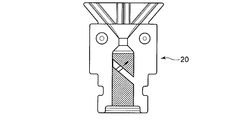
- the blocking part 120b dams the liquid flowing in the flow path formed by combining the flow path elements 120w, and the fluid along the blocking part 120b becomes a swirl flow. It extends obliquely with respect to the direction. And the penetration part 120t is provided so that the interruption
- a vane element 120v is configured by the blocking portion 120b and the through portion 120t.
Landscapes
- Engineering & Computer Science (AREA)
- Water Supply & Treatment (AREA)
- Mechanical Engineering (AREA)
- Nozzles (AREA)
- Cleaning By Liquid Or Steam (AREA)
Abstract
Description
10s 供給口
10w 流路
10e 噴射口
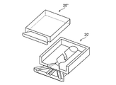
20、20’、20” ノズル分割体
20s 供給口要素
20w 流路要素
20e 噴射口要素
20v ベーン要素
20b 遮断部
20t 貫通部
20n 絞り部
20f 平面部
20p 平板部
20g 溝パターン
20q 凸部
20r 凹部
20a 係止突起
20h ヒンジ部
30 ノズルボディ
30a 被係止孔
40 Oリング
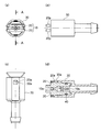
110 ノズル
120 ノズル分割体
120s 供給口要素
120w 流路要素
120e 噴射口要素
120v ベーン要素
120b 遮断部
120t 貫通部
120n 絞り部
130 ノズルボディ 10
Claims (8)
- 液体が供給される供給口と液体が噴射される噴射口とを有するノズルを備え、
前記ノズルは、複数のノズル分割体が組み合わされて構成されており、
前記複数のノズル分割体の各々には、前記供給口から供給される液体を旋回させるベーン要素が一体的に構成されている
ことを特徴とするスプレーノズル。 A nozzle having a supply port through which liquid is supplied and an injection port through which liquid is injected;
The nozzle is configured by combining a plurality of nozzle division bodies,
In each of the plurality of nozzle division bodies, a vane element that swirls the liquid supplied from the supply port is integrally formed. - 各ノズル分割体には、前記噴射口の前方側に、左右方向に延びる平面部が設けられている
ことを特徴とする請求項1に記載のスプレーノズル。 The spray nozzle according to claim 1, wherein each nozzle divided body is provided with a flat portion extending in the left-right direction on the front side of the ejection port. - 前記平面部には、溝またはリブのパターンが形成されている
ことを特徴とする請求項2に記載のスプレーノズル。 The spray nozzle according to claim 2, wherein a pattern of grooves or ribs is formed on the flat portion. - 前記ノズル分割体の一方には、互いに係合可能な凸部及び凹部の一方が形成されており、
前記ノズル分割体の他方には、前記凸部及び前記凹部の他方が形成されている
ことを特徴とする請求項1乃至3のいずれかに記載のスプレーノズル。 One of the nozzle divided bodies is formed with one of a convex portion and a concave portion that can be engaged with each other,
The spray nozzle according to any one of claims 1 to 3, wherein the other of the convex portion and the concave portion is formed on the other of the nozzle divided bodies. - 前記複数のノズル分割体の各々には、前記供給口から前記噴射口まで直線的に延びる流路要素が設けられており、
前記ベーン要素は、前記流路要素を堰き止めるように延びる遮断部を有している
ことを特徴とする請求項1乃至4のいずれかに記載のスプレーノズル。 Each of the plurality of nozzle division bodies is provided with a flow path element extending linearly from the supply port to the injection port,
The spray nozzle according to any one of claims 1 to 4, wherein the vane element has a blocking portion extending so as to block the flow path element. - 前記遮断部は、当該遮断部に沿う流体が旋回流となるように、前記流路要素の方向に対して斜めに延びている
ことを特徴とする請求項5に記載のスプレーノズル。 The spray nozzle according to claim 5, wherein the blocking portion extends obliquely with respect to the direction of the flow path element so that the fluid along the blocking portion becomes a swirling flow. - 前記ノズルは、ノズルボディに取り付けられており、
前記ノズルボディ及び前記ノズルの一方には、互いに係止可能な係止部及び被係止部の一方が形成されており、
前記ノズルボディ及び前記ノズルの他方には、前記係止部及び前記被係止部の他方が形成されている
ことを特徴とする請求項1乃至6のいずれかに記載のスプレーノズル。 The nozzle is attached to a nozzle body;
One of the nozzle body and the nozzle is formed with one of a locking part and a locked part that can be locked to each other,
The spray nozzle according to any one of claims 1 to 6, wherein the other of the locking portion and the locked portion is formed on the other of the nozzle body and the nozzle. - 前記ノズルは、ノズルボディに取り付けられており、
前記ノズルボディ及び前記ノズルの一方には、互いに溶着可能な溶着部及び被溶着部の一方が形成されており、
前記ノズルボディ及び前記ノズルの他方には、前記溶着部及び前記被溶着部の他方が形成されている
ことを特徴とする請求項1乃至6のいずれかに記載のスプレーノズル。 The nozzle is attached to a nozzle body;
One of the nozzle body and the nozzle is formed with one of a welded portion and a welded portion that can be welded to each other,
The spray nozzle according to claim 1, wherein the other of the welded portion and the welded portion is formed on the other of the nozzle body and the nozzle.
Priority Applications (4)
| Application Number | Priority Date | Filing Date | Title |
|---|---|---|---|
| JP2015554899A JP6270875B2 (en) | 2013-12-24 | 2014-12-22 | spray nozzle |
| CN201480071033.3A CN105848786B (en) | 2013-12-24 | 2014-12-22 | Spray nozzle |
| EP14875729.7A EP3090807B1 (en) | 2013-12-24 | 2014-12-22 | Spray nozzle |
| US15/107,669 US10155502B2 (en) | 2013-12-24 | 2014-12-22 | Airflow-direction adjustment device |
Applications Claiming Priority (2)
| Application Number | Priority Date | Filing Date | Title |
|---|---|---|---|
| JP2013265841 | 2013-12-24 | ||
| JP2013-265841 | 2013-12-24 |
Publications (1)
| Publication Number | Publication Date |
|---|---|
| WO2015098877A1 true WO2015098877A1 (en) | 2015-07-02 |
Family
ID=53478729
Family Applications (1)
| Application Number | Title | Priority Date | Filing Date |
|---|---|---|---|
| PCT/JP2014/083976 WO2015098877A1 (en) | 2013-12-24 | 2014-12-22 | Spray nozzle |
Country Status (6)
| Country | Link |
|---|---|
| US (1) | US10155502B2 (en) |
| EP (1) | EP3090807B1 (en) |
| JP (1) | JP6270875B2 (en) |
| KR (1) | KR101673700B1 (en) |
| CN (1) | CN105848786B (en) |
| WO (1) | WO2015098877A1 (en) |
Families Citing this family (5)
| Publication number | Priority date | Publication date | Assignee | Title |
|---|---|---|---|---|
| JP6465836B2 (en) * | 2016-04-28 | 2019-02-06 | 株式会社ニフコ | Nozzle device |
| CA3036552A1 (en) | 2016-09-13 | 2018-03-22 | Spectrum Brands, Inc. | Swirl pot shower head engine |
| EP3409972A1 (en) | 2017-06-01 | 2018-12-05 | Öhlins Racing AB | Pressurized telescopic front fork leg, front fork and vehicle |
| KR101909984B1 (en) | 2017-11-30 | 2018-10-19 | 주식회사 쓰리디프리욜 | Nozzle for cleaning substrate |
| CN114950749B (en) * | 2022-06-07 | 2023-02-07 | 江西昌河汽车有限责任公司 | Tool for baking or cooling and shaving oil sludge |
Citations (6)
| Publication number | Priority date | Publication date | Assignee | Title |
|---|---|---|---|---|
| JPS55177869U (en) * | 1980-05-14 | 1980-12-20 | ||
| JPS5669959U (en) * | 1979-10-31 | 1981-06-09 | ||
| JPS58171250U (en) * | 1982-05-07 | 1983-11-15 | 第一精工株式会社 | window washer nozzle |
| US5743468A (en) * | 1995-04-06 | 1998-04-28 | Incro Limited | Spraying apparatus and nozzle devices |
| JP2001010452A (en) * | 1999-06-25 | 2001-01-16 | Asmo Co Ltd | Washer nozzle device for vehicle |
| JP2005081318A (en) | 2003-09-11 | 2005-03-31 | Nippon Vinylon Kk | Diffusion nozzle and liquid spray apparatus |
Family Cites Families (19)
| Publication number | Priority date | Publication date | Assignee | Title |
|---|---|---|---|---|
| US2999648A (en) * | 1959-08-10 | 1961-09-12 | Spraying Systems Co | Side inlet conical spray nozzle |
| JPS4816504Y1 (en) * | 1969-05-16 | 1973-05-11 | ||
| JP2527677Y2 (en) * | 1991-01-31 | 1997-03-05 | いすゞ自動車株式会社 | Fuel injection nozzle |
| CN1180340A (en) * | 1995-04-06 | 1998-04-29 | 英克罗有限公司 | Spraying apparatus nozzle |
| JPH09155266A (en) * | 1995-12-05 | 1997-06-17 | Hitachi Ltd | Coating device |
| DE69611547T2 (en) * | 1996-02-28 | 2001-08-23 | Incro Ltd | SPRAYING DEVICES AND NOZZLES |
| JPH10192742A (en) * | 1996-12-27 | 1998-07-28 | Hanshin Jitsugyo Kk | Discharge nozzle valve assembly and deodorizing device using same |
| US5975431A (en) * | 1997-05-21 | 1999-11-02 | Asmo Co., Ltd. | Washer nozzle and washer apparatus for vehicle |
| JP2001179626A (en) * | 1999-12-22 | 2001-07-03 | Koyo Mach Ind Co Ltd | Coolant nozzle device for dresser |
| JP2002067887A (en) * | 2000-08-30 | 2002-03-08 | Nippon Vinylon Kk | Variable jet direction diffusion nozzle and liquid jet device |
| JP3801967B2 (en) | 2001-08-28 | 2006-07-26 | 株式会社いけうち | NOZZLE AND METHOD OF INJECTING FLUID TO INTERNAL PERIPHERAL SURFACE BY NOZZLE |
| US6969015B1 (en) * | 2003-06-17 | 2005-11-29 | Automatic Bar Controls Inc. | Particulate sauce dispensing nozzle |
| JP4504641B2 (en) * | 2003-07-30 | 2010-07-14 | 株式会社共立合金製作所 | Spray nozzle and spraying method using the same |
| EP1566220B1 (en) | 2004-02-20 | 2009-07-08 | Kautex Textron GmbH & Co. KG. | Screen wash nozzle |
| JP3104320U (en) * | 2004-03-31 | 2004-09-16 | 株式会社中澤金属製作所 | Nose washing nozzle |
| US7316362B2 (en) * | 2004-08-26 | 2008-01-08 | Nippon Vinylon Co., Ltd. | Spraying angular variable washer nozzle device |
| JP4692005B2 (en) * | 2005-02-14 | 2011-06-01 | マックス株式会社 | Hot water sprinkling nozzle, hot water sprinkling device, hot water sprinkling chamber and building |
| MX2008011252A (en) | 2006-03-07 | 2008-09-10 | Boehringer Ingelheim Int | Swirl. |
| EP2056968B1 (en) * | 2006-06-16 | 2014-06-18 | Bowles Fluidics Corporation | Fluidic device yielding three-dimensional spray patterns |
-
2014
- 2014-11-21 KR KR1020140163669A patent/KR101673700B1/en active IP Right Grant
- 2014-12-22 JP JP2015554899A patent/JP6270875B2/en active Active
- 2014-12-22 WO PCT/JP2014/083976 patent/WO2015098877A1/en active Application Filing
- 2014-12-22 EP EP14875729.7A patent/EP3090807B1/en active Active
- 2014-12-22 CN CN201480071033.3A patent/CN105848786B/en active Active
- 2014-12-22 US US15/107,669 patent/US10155502B2/en active Active
Patent Citations (6)
| Publication number | Priority date | Publication date | Assignee | Title |
|---|---|---|---|---|
| JPS5669959U (en) * | 1979-10-31 | 1981-06-09 | ||
| JPS55177869U (en) * | 1980-05-14 | 1980-12-20 | ||
| JPS58171250U (en) * | 1982-05-07 | 1983-11-15 | 第一精工株式会社 | window washer nozzle |
| US5743468A (en) * | 1995-04-06 | 1998-04-28 | Incro Limited | Spraying apparatus and nozzle devices |
| JP2001010452A (en) * | 1999-06-25 | 2001-01-16 | Asmo Co Ltd | Washer nozzle device for vehicle |
| JP2005081318A (en) | 2003-09-11 | 2005-03-31 | Nippon Vinylon Kk | Diffusion nozzle and liquid spray apparatus |
Also Published As
| Publication number | Publication date |
|---|---|
| CN105848786B (en) | 2018-06-12 |
| JPWO2015098877A1 (en) | 2017-03-23 |
| KR20150075020A (en) | 2015-07-02 |
| JP6270875B2 (en) | 2018-01-31 |
| US10155502B2 (en) | 2018-12-18 |
| EP3090807A4 (en) | 2017-10-18 |
| US20160325714A1 (en) | 2016-11-10 |
| KR101673700B1 (en) | 2016-11-07 |
| EP3090807B1 (en) | 2020-09-09 |
| EP3090807A1 (en) | 2016-11-09 |
| CN105848786A (en) | 2016-08-10 |
Similar Documents
| Publication | Publication Date | Title |
|---|---|---|
| JP6270875B2 (en) | spray nozzle | |
| JP6559768B2 (en) | Small split lip shear washer nozzle | |
| US6354515B1 (en) | Washer nozzle device for vehicles | |
| EP2403651B1 (en) | High efficiency, multiple throat fluidic oscillator | |
| JP2008150012A (en) | Spray washer nozzle integrated with housing for vehicle | |
| JP5525918B2 (en) | Washer nozzle | |
| JP2005059651A (en) | Washer nozzle for vehicle and washer device for vehicle | |
| KR101534934B1 (en) | Double spray nozzle device of vehicle | |
| JP4658771B2 (en) | Vehicle washer nozzle and vehicle washer device | |
| JP4119443B2 (en) | Washer nozzle | |
| JP2011177677A (en) | Aerosol button and aerosol cap | |
| JP2005225263A (en) | Nozzle tip and vehicular washer nozzle | |
| KR101710411B1 (en) | Pintle injector with overdrive function and method for controlling flow of the same | |
| JP5580603B2 (en) | Aerosol button and aerosol cap | |
| CN107716146B (en) | Water outlet and splashing mechanism | |
| JP5210242B2 (en) | Cleaning device for vehicle lamp | |
| JP2008184058A (en) | Washer nozzle | |
| JP2008155662A (en) | Washer nozzle mounting structure | |
| JP2012223886A (en) | Liquid ejection head and flow path member | |
| JP2009029330A (en) | Washer nozzle | |
| CN106152128B (en) | Burner | |
| JP2005199273A (en) | Snow melting nozzle | |
| JP2012040898A (en) | Washing device of lighting fixture for vehicle | |
| WO2021075096A1 (en) | Fluid spray nozzle, and vehicle sensor cleaning device | |
| JP3940075B2 (en) | Vehicle washer nozzle and vehicle washer device |
Legal Events
| Date | Code | Title | Description |
|---|---|---|---|
| 121 | Ep: the epo has been informed by wipo that ep was designated in this application |
Ref document number: 14875729 Country of ref document: EP Kind code of ref document: A1 |
|
| ENP | Entry into the national phase |
Ref document number: 2015554899 Country of ref document: JP Kind code of ref document: A |
|
| WWE | Wipo information: entry into national phase |
Ref document number: 15107669 Country of ref document: US |
|
| NENP | Non-entry into the national phase |
Ref country code: DE |
|
| REEP | Request for entry into the european phase |
Ref document number: 2014875729 Country of ref document: EP |
|
| WWE | Wipo information: entry into national phase |
Ref document number: 2014875729 Country of ref document: EP |