JP5580603B2 - Aerosol button and aerosol cap - Google Patents
Aerosol button and aerosol cap Download PDFInfo
- Publication number
- JP5580603B2 JP5580603B2 JP2010002196A JP2010002196A JP5580603B2 JP 5580603 B2 JP5580603 B2 JP 5580603B2 JP 2010002196 A JP2010002196 A JP 2010002196A JP 2010002196 A JP2010002196 A JP 2010002196A JP 5580603 B2 JP5580603 B2 JP 5580603B2
- Authority
- JP
- Japan
- Prior art keywords
- nozzle
- aerosol
- tip
- button
- outflow
- Prior art date
- Legal status (The legal status is an assumption and is not a legal conclusion. Google has not performed a legal analysis and makes no representation as to the accuracy of the status listed.)
- Active
Links
Images


Description
本発明は、エアゾール容器に収容されている内容物を噴射するために、エアゾール容器に装着されるエアゾールキャップに関し、特に十字状の広角な噴霧パターンを得るエアゾールボタンに関する。 The present invention relates to an aerosol cap that is attached to an aerosol container in order to inject the contents contained in the aerosol container, and more particularly to an aerosol button that obtains a cross-shaped wide-angle spray pattern.
従来から消臭剤等の内容物と液化ガスとが充填されたエアゾール容器に装着されるエアゾール用ノズルが知られている(例えば、特許文献1)。このエアゾール用ノズルは、使用時に押釦を押下することによりノズル体から内容物を噴射させることができる。 2. Description of the Related Art Conventionally, there is known an aerosol nozzle that is attached to an aerosol container filled with contents such as a deodorant and a liquefied gas (for example, Patent Document 1). This aerosol nozzle can eject the contents from the nozzle body by depressing a push button during use.
図7に示したエアゾール用ノズル100は、押釦101にノズル体103を設け、ステム105の押圧時にエアゾール容器107の内部とノズル体103とを連通させる。ノズル体103には、内容物を流出させる流出路109が軸方向に形成されている。
In the
図8に示したノズル体103は、流出路109の流出先端部111が円形に形成されている。流出先端部111には、流出路109と直交する拡散割溝113が形成されている。この拡散割溝113の底部115が流出先端部111に切り込んで形成されている。これにより、拡散割溝113と流出路109の流出先端部111とが連通して、噴口117が形成されている。
In the
使用時は、押釦101を押圧してエアゾール容器107のバルブ機構(図示せず)が開弁すると、内容物がノズル体103の流出路109に流入する。流出先端部111に到達した内容物は、流出先端部111の内面で拡散して、流出先端部111から外部に噴出する。その噴出方向は、拡散割溝113によって両側が規制され、上下方向のみに拡散し、左右方向に一定の厚みを有する側面視で扇形状に噴射される。これにより、正面視で長方形状に近似した噴霧パターンを得ることができる。
In use, when the
しかしながら、従来のワイド噴射ノズルであるエアゾール用ノズル100は、拡散割溝113によって噴射を上下方向に拡散させ、左右方向には一定の厚みに制限していたので、左右方向にも拡散させたい場合には適していなかった。
そのため、上下方向のみに形成していた拡散割溝113を左右方向にも形成して、所謂、十字噴口による噴霧パターンを検討した。その結果、十字噴口では均一な拡散による十字形状の噴霧パターンを得ることはできなかった。
However, the
For this reason,
本発明は、上記課題に鑑みてなされたものであり、十字形状に均一拡散する噴霧パターンを得ることができるエアゾールボタンおよびエアゾールキャップを提供することを目的としている。 This invention is made | formed in view of the said subject, and it aims at providing the aerosol button and the aerosol cap which can obtain the spray pattern which spreads uniformly in a cross shape.
本発明に係る上記目的は、下記構成により達成される。
(1)エアゾール容器のステムに挿着されて前記ステムを押下することで前記エアゾール容器内の内容物を噴射するエアゾールボタンであって、一端がステム挿入孔として開口する第1流出路の形成されたボタン本体と、前記第1流出路と連通した第2流出路の先端面で開口させて噴口とするノズル体と、を備え、該ノズル体は、前記第2流出路の先端面で開口して主噴射する第1噴口と、該第1噴口の両側に一対形成され、前記第2流出路に対して横方向に傾斜角を有する第3流出路の先端面で開口する第2噴口と、を有し、前記第1噴口には、前記第2流出路の流出先端部に所定幅の拡散割溝が切り込んで形成され、これによって拡散割溝の溝方向に幅広の噴霧パターンを得ることができ、前記第2噴口は、前記第1噴口の幅広の噴霧パターンの両側で前記横方向の傾斜角をもって噴射され、これによって十字形状の噴霧パターンを得ることができることを特徴とするエアゾールボタン。
The above object of the present invention is achieved by the following configuration.
(1) An aerosol button that is inserted into a stem of an aerosol container and ejects the contents in the aerosol container by pressing the stem, and is formed with a first outflow path having one end opened as a stem insertion hole. A button body, and a nozzle body that is opened at the front end surface of the second outflow passage communicating with the first outflow passage to serve as a nozzle, and the nozzle body opens at the front end surface of the second outflow passage. A first nozzle hole for main injection, and a second nozzle hole that is formed in a pair on both sides of the first nozzle hole and opens at a tip surface of a third outlet channel having an inclination angle in a lateral direction with respect to the second outlet channel; The first nozzle hole is formed with a diffusion split groove having a predetermined width cut into the outflow tip of the second outflow path, thereby obtaining a wide spray pattern in the groove direction of the diffusion split groove. And the second nozzle hole is wider than the first nozzle hole. Injected with a tilt angle of the laterally opposite sides of the over emissions, aerosol button, characterized in that it makes it possible to obtain the spray pattern of the cross-shaped.
前記構成のエアゾールボタンによれば、ノズル体は、第2流出路の先端面で開口して主噴射する第1噴口と、第1噴口の両側に一対形成され、第2流出路に対して横方向に傾斜角を有する第3流出路の先端面で開口する第2噴口とを有している。これにより、ボタン本体の押下に伴ってエアゾール容器内の内容物が第1噴口と第2噴口から噴射されることで、十字形状で均一拡散する噴霧パターンを得ることができる。 According to the aerosol button having the above-described configuration, the nozzle body is formed in a pair on both sides of the first injection port that is opened at the front end surface of the second outflow passage and main injection, and is lateral to the second outflow passage. And a second injection hole that opens at the front end surface of the third outflow passage having an inclination angle in the direction. Thereby, the spray pattern which spreads uniformly in a cross shape can be obtained because the contents in the aerosol container are ejected from the first and second nozzles as the button body is pressed.
(2)(1)のエアゾールボタンであって、前記第1噴口は、前記ノズル体先端に挿着された噴口チップによって形成され、前記第3流出路は、主に前記ノズル体側の前記第2流出路を形成する内周面上に形成された内周溝によって形成されていることを特徴とするエアゾールボタン。 (2) The aerosol button according to (1), wherein the first nozzle hole is formed by a nozzle tip inserted into the tip of the nozzle body, and the third outflow path is mainly the second nozzle on the nozzle body side. An aerosol button formed by an inner circumferential groove formed on an inner circumferential surface forming an outflow path.
前記構成のエアゾールボタンによれば、第3流出路は、主にノズル体側の内周面上の内周溝によって形成されているので、ノズル体の成形と同時に内周溝を成形することができる。これにより、ノズル体先端に噴口チップを挿着することで、第3流出路を確実に形成できるので、均一拡散する噴霧パターンを確実に得ることができると共に、コスト低減を図ることができる。 According to the aerosol button having the above-described configuration, the third outflow path is mainly formed by the inner peripheral groove on the inner peripheral surface on the nozzle body side, so that the inner peripheral groove can be formed simultaneously with the molding of the nozzle body. . Thereby, since the third outflow passage can be reliably formed by inserting the nozzle tip at the tip of the nozzle body, it is possible to reliably obtain a spray pattern that uniformly diffuses and to reduce the cost.
(3)(1)のエアゾールボタンであって、前記第1噴口は、前記ノズル体先端に挿着された噴口チップによって形成され、前記第3流出路は、主に前記噴口チップ側の外周面上に形成された外周溝によって形成されていることを特徴とするエアゾールボタン。 (3) The aerosol button according to (1), wherein the first nozzle hole is formed by a nozzle tip inserted into the tip of the nozzle body, and the third outflow path is mainly an outer peripheral surface on the nozzle tip side. An aerosol button characterized by being formed by an outer peripheral groove formed on the top.
前記構成のエアゾールボタンによれば、第3流出路は、主に噴口チップ側の外周面上の外周溝によって形成されているので、噴口チップの成形と同時に外周溝を成形することができる。これにより、ノズル体先端に噴口チップを挿着することで、第3流出路を確実に形成できるので、均一拡散する噴霧パターンを確実に得ることができると共に、コスト低減を図ることができる。 According to the aerosol button having the above-described configuration, the third outflow path is mainly formed by the outer peripheral groove on the outer peripheral surface on the nozzle tip side, so that the outer peripheral groove can be formed simultaneously with the molding of the nozzle tip. Thereby, since the third outflow passage can be reliably formed by inserting the nozzle tip at the tip of the nozzle body, it is possible to reliably obtain a spray pattern that uniformly diffuses and to reduce the cost.
(4)(1)〜(3)のいずれかに記載のエアゾールボタンと、前記エアゾール容器に嵌合装着されるキャップ本体とが一体形成されていることを特徴とするエアゾールキャップ。 (4) An aerosol cap, wherein the aerosol button according to any one of (1) to (3) and a cap body that is fitted and attached to the aerosol container are integrally formed.
前記構成のエアゾールキャップによれば、ノズル体とボタン本体を一体にしたエアゾールボタンに、さらにキャップ本体が一体形成されることで、従来別部品であったノズル体、ボタン本体およびキャップ本体が1部品となる。これにより、十字形状に均一拡散する噴霧パターンを得ることができると共に、コスト低減を図ることができる。 According to the aerosol cap having the above-described configuration, the nozzle body, the button body, and the cap body, which are conventionally separate parts, are formed as one part by further forming the cap body integrally with the aerosol button in which the nozzle body and the button body are integrated. It becomes. Thereby, while being able to obtain the spray pattern which diffuses uniformly in a cross shape, cost reduction can be aimed at.
本発明に係るエアゾールボタンおよびエアゾールキャップによれば、ノズル体は、第2流出路の先端面で開口して主噴射する第1噴口と、第1噴口の両側に一対形成され、第2流出路に対して横方向に傾斜角を有する第3流出路の先端面で開口する第2噴口とを有している。したがって、ボタン本体の押下に伴ってエアゾール容器内の内容物が第1噴口と第2噴口から噴射されることで、十字形状で均一拡散する噴霧パターンを得ることができる。 According to the aerosol button and the aerosol cap according to the present invention, the nozzle body is formed in a pair on the both sides of the first injection port and the first injection port that are opened at the front end surface of the second outflow channel and main injection, and the second outflow channel And a second injection hole that opens at the front end surface of the third outflow passage having an inclination angle in the lateral direction. Therefore, when the contents of the aerosol container are ejected from the first and second nozzles as the button body is pressed, it is possible to obtain a spray pattern that spreads uniformly in a cross shape.
以下、本発明の第1実施形態を図1〜図5に基づいて詳細に説明する。
図1及び図2に示すように、本実施形態によるエアゾールキャップ10は、エアゾール容器11の上部に嵌合装着されるキャップ本体13とエアゾールボタン20が、一体的に形成されている。エアゾールボタン20は、ボタン本体21の一側面から突出した円筒状のノズル体22を備えている。エアゾールキャップ10は、エアゾール容器11のステムに挿着され、使用時にエアゾールボタン20を押下することでエアゾール容器内の消臭剤等の原液と噴射剤である液化ガスとの混合内容物を噴霧状に噴射する。
Hereinafter, a first embodiment of the present invention will be described in detail with reference to FIGS.
As shown in FIGS. 1 and 2, the
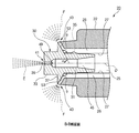
図3及び図4に示すように、エアゾールボタン20のボタン本体21は、下端側にステム挿入孔23として開口する第1流出路24を備えている。ノズル体22は、ボタン本体21の側面に突設され、第1流出路24の中心軸Cと直交する軸線Dに沿って穿設された第2流出路25を備えている。また、ノズル体22は、第2流出路25の先端面で開口して主噴射する第1噴口41と、該第1噴口41の両側に一対の第2噴口43とを有している。
As shown in FIGS. 3 and 4, the
第2流出路25を形成するノズル体22の先端には、噴口チップ30が挿着されている。噴口チップ30は、筒状の装着部31と、該装着部31先端の噴射部33とを備えている。噴射部33は、先端の流出先端部49にチップ流出路45と直交する拡散割溝39が形成されている。即ち、拡散割溝39の底部51が流出先端部49に切り込んで形成されており、拡散割溝39とチップ流出路45の流出先端部49とが連通して第1噴口41を形成している。この拡散割溝39の溝幅Gは均一に形成されているが、溝深さHは軸線Dから上下の側端にかけてほぼ半円形に形成されている。
A
図5に示すように、噴口チップ30の外周には、装着部31と噴射部33との間に環状の鍔部37を有するとともに、装着部31に固定用の爪部35を有している。この鍔部37の爪部35側は、鈍角である傾斜角θの傾斜面53を有している。また、ノズル体22は、軸線Dに沿って第2流出路25を形成する内周面上の対向した位置に左右一対の内周溝27が形成されている。このノズル体22の内周溝27と噴口チップ30の装着部31の外周面とによって第3流出路26が形成されている。
As shown in FIG. 5, the outer periphery of the
第3流出路26の前端部は、第2流出路25に対して鍔部37の傾斜角θを有する傾斜面53によって左右方向(拡散方向)に屈曲している。この屈曲した第3流出路26の先端には、第1噴口41に対して横方向への拡散角α(=π−θ)を有する第2噴口43が開口している。したがって、第1噴口41によって縦方向のみに拡散し、横方向に一定の厚みを有する主噴射Eが形成されるとともに、左右一対の第2噴口43によって横方向のみに拡散角αを有し、縦方向に一定の厚みを有する拡散噴射Fが形成される。この主噴射Eと拡散噴射Fが同時に噴射されることにより全体的に十字形状の噴霧パターンが形成される。
The front end portion of the
上述したように本実施形態のエアゾールボタン20によれば、ノズル体22は、第2流出路25の先端面で開口して主噴射する第1噴口41と、第1噴口41の両側に一対形成され、第2流出路25に対して横方向に傾斜角θを有する第3流出路26の先端面で開口する第2噴口43とを有している。これにより、ボタン本体21の押下に伴ってエアゾール容器11内の内容物が第1噴口41と第2噴口43とから同時に噴射される。これにより、全体的に十字形状で且つ均一拡散する噴霧パターンを実現することができる。
As described above, according to the
また、第3流出路26は、主にノズル体22側の内周面上の内周溝27によって形成されているので、ノズル体22の成形と同時に内周溝27を成形することができる。これにより、ノズル体22先端に噴口チップ30を挿着することで、第3流出路26を確実に形成できるので、均一拡散する噴霧パターンを確実に得ることができると共に、コスト低減を図ることができる。
Further, since the
また、本実施形態のエアゾールキャップ10によれば、ノズル体22とボタン本体21を一体にしたエアゾールボタン20に、さらにキャップ本体13が一体形成されることで、従来別部品であったノズル体22、ボタン本体21及びキャップ本体13が1部品となる。これにより、全体的に十字形状で且つ均一拡散する噴霧パターンを実現することができると共に、コスト低減を図ることができる。
In addition, according to the
次に、本発明の第2実施形態を図6に基づいて説明する。なお、上記第1実施形態と同じ構成及び作用については、同一符号を付すことで説明を簡略化又は省略する。 Next, a second embodiment of the present invention will be described with reference to FIG. In addition, about the same structure and effect | action as the said 1st Embodiment, description is simplified or abbreviate | omitted by attaching | subjecting the same code | symbol.
図6に示すように、本実施形態のエアゾールボタン40は、第2流出路25の先端面で開口する第1噴口41及び第1噴口41の両側に形成される一対の第2噴口43の構成及び配置位置は同じであるが、第2噴口43に向う第3流出路67の構成が第1実施形態と異なっている。即ち、ノズル体22の先端に挿着される噴口チップ60は、筒状の装着部61の外周面の対向した位置に一対の外周溝65を有している。この外周溝65とノズル体22側の第2流出路25を形成する内周面29とによって第3流出路67が形成されている。
As shown in FIG. 6, the
第3流出路67の前端部は、第2流出路25に対して横方向に傾斜角θを有する鍔部37の傾斜面53によって拡散方向に屈曲しており、第1噴口41に対して横方向に拡散角αを有する第2噴口43が開口している構成は第1実施形態と同じである。したがって、第1噴口41によって縦方向のみに拡散し、横方向に一定の厚みを有する主噴射Eと、左右一対の第2噴口43によって横方向のみに拡散角αを有し、縦方向に一定の厚みを有する拡散噴射Fとが同時に噴射される。これにより、全体的に十字形状の噴霧パターンが形成される。
The front end portion of the
上述したように本実施形態のエアゾールボタン40によれば、第3流出路67は、主に噴口チップ60側の外周面上の外周溝65によって形成されているので、噴口チップ60の成形と同時に外周溝65を成形することができる。これにより、ノズル体22先端に噴口チップ60を挿着することで、第3流出路67を確実に形成できるので、均一拡散する噴霧パターンを確実に得ることができると共に、コスト低減を図ることができる。
As described above, according to the
なお、上述した実施形態では、エアゾールボタンの側方から噴射する実施形態について説明したが、本発明はこの実施形態に限定されるものではなく、エアゾールボタンの上方から噴射する実施形態にも適用することができる。 In addition, although embodiment mentioned above demonstrated embodiment injected from the side of an aerosol button, this invention is not limited to this embodiment, It applies also to embodiment injected from the upper direction of an aerosol button. be able to.
10…エアゾールボタンキャップ
11…エアゾール容器
13…キャップ本体
20、40…エアゾールボタン
21…ボタン本体
22…ノズル体
24…第1流出路
25…第2流出路
26、67…第3流出路
27…内周溝
30、60…噴口チップ
41…第1噴口
43…第2噴口
45…チップ流出路
65…外周溝
α…拡散角
θ…傾斜角
E…主噴射
F…拡散噴射
DESCRIPTION OF
Claims (4)
一端がステム挿入孔として開口する第1流出路の形成されたボタン本体と、
前記第1流出路と連通した第2流出路の先端面で開口させて噴口とするノズル体と、を備え、
該ノズル体は、前記第2流出路の先端面で開口して主噴射する第1噴口と、
該第1噴口の両側に一対形成され、前記第2流出路に対して横方向に傾斜角を有する第3流出路の先端面で開口する第2噴口と、を有し、
前記第1噴口には、前記第2流出路の流出先端部に所定幅の拡散割溝が切り込んで形成され、これによって拡散割溝の溝方向に幅広の噴霧パターンを得ることができ、
前記第2噴口は、前記第1噴口の幅広の噴霧パターンの両側で前記横方向の傾斜角をもって噴射され、
これによって十字形状の噴霧パターンを得ることができる、
ことを特徴とするエアゾールボタン。 An aerosol button that is inserted into a stem of an aerosol container and injects the contents in the aerosol container by pressing the stem,
A button body formed with a first outflow path having one end opened as a stem insertion hole;
A nozzle body that is opened at the front end surface of the second outflow path that communicates with the first outflow path and serves as a nozzle,
The nozzle body has a first injection hole that is opened at a front end surface of the second outflow passage and main injection is performed;
A pair of second nozzle holes formed on both sides of the first nozzle hole and opening at a tip end surface of a third outlet channel having an inclination angle in a lateral direction with respect to the second outlet channel;
In the first nozzle hole, a diffusion split groove having a predetermined width is formed by cutting into the outflow tip portion of the second outflow path, thereby obtaining a wide spray pattern in the groove direction of the diffusion split groove,
The second nozzle hole is jetted with the lateral inclination angle on both sides of the wide spray pattern of the first nozzle hole,
A cross-shaped spray pattern can thus be obtained ,
Aerosol button characterized by that.
前記第1噴口は、前記ノズル体先端に挿着された噴口チップによって形成され、
前記第3流出路は、主に前記ノズル体側の前記第2流出路を形成する内周面上に形成された内周溝によって形成されていることを特徴とするエアゾールボタン。 The aerosol button according to claim 1,
The first nozzle hole is formed by a nozzle tip inserted into the nozzle body tip,
The aerosol button is characterized in that the third outflow path is mainly formed by an inner peripheral groove formed on an inner peripheral surface forming the second outflow path on the nozzle body side.
前記第1噴口は、前記ノズル体先端に挿着された噴口チップによって形成され、
前記第3流出路は、主に前記噴口チップ側の外周面上に形成された外周溝によって形成されていることを特徴とするエアゾールボタン。 The aerosol button according to claim 1,
The first nozzle hole is formed by a nozzle tip inserted into the nozzle body tip,
The aerosol button is characterized in that the third outflow passage is formed mainly by an outer peripheral groove formed on an outer peripheral surface on the nozzle tip side.
Priority Applications (1)
| Application Number | Priority Date | Filing Date | Title |
|---|---|---|---|
| JP2010002196A JP5580603B2 (en) | 2010-01-07 | 2010-01-07 | Aerosol button and aerosol cap |
Applications Claiming Priority (1)
| Application Number | Priority Date | Filing Date | Title |
|---|---|---|---|
| JP2010002196A JP5580603B2 (en) | 2010-01-07 | 2010-01-07 | Aerosol button and aerosol cap |
Publications (2)
| Publication Number | Publication Date |
|---|---|
| JP2011139994A JP2011139994A (en) | 2011-07-21 |
| JP5580603B2 true JP5580603B2 (en) | 2014-08-27 |
Family
ID=44456242
Family Applications (1)
| Application Number | Title | Priority Date | Filing Date |
|---|---|---|---|
| JP2010002196A Active JP5580603B2 (en) | 2010-01-07 | 2010-01-07 | Aerosol button and aerosol cap |
Country Status (1)
| Country | Link |
|---|---|
| JP (1) | JP5580603B2 (en) |
Families Citing this family (3)
| Publication number | Priority date | Publication date | Assignee | Title |
|---|---|---|---|---|
| JP2011177677A (en) * | 2010-03-03 | 2011-09-15 | Maruichi Valve Co Ltd | Aerosol button and aerosol cap |
| JP6914017B2 (en) * | 2016-08-10 | 2021-08-04 | 株式会社ダイゾー | Injection unit and aerosol products |
| JP6810447B2 (en) * | 2016-09-12 | 2021-01-06 | 株式会社三谷バルブ | Spray cap for aerosol and aerosol |
Family Cites Families (8)
| Publication number | Priority date | Publication date | Assignee | Title |
|---|---|---|---|---|
| JPS4892607U (en) * | 1972-02-10 | 1973-11-07 | ||
| JPH0688006B2 (en) * | 1985-12-30 | 1994-11-09 | アロイ工器株式会社 | Spray gun for painting |
| JPH055975Y2 (en) * | 1987-06-18 | 1993-02-16 | ||
| JP2769962B2 (en) * | 1993-04-21 | 1998-06-25 | アロイ工器株式会社 | Air-added sprayer suitable for painting |
| JP4003825B2 (en) * | 2002-01-16 | 2007-11-07 | 株式会社三谷バルブ | Wide angle injection button |
| JP2004016833A (en) * | 2002-06-12 | 2004-01-22 | Mitani Valve Co Ltd | Ejection button for infiltration |
| JP4166766B2 (en) * | 2005-05-20 | 2008-10-15 | 大日本除蟲菊株式会社 | Aerosol products |
| JP2008168193A (en) * | 2007-01-10 | 2008-07-24 | Earth Chem Corp Ltd | Aerosol spraying device |
-
2010
- 2010-01-07 JP JP2010002196A patent/JP5580603B2/en active Active
Also Published As
| Publication number | Publication date |
|---|---|
| JP2011139994A (en) | 2011-07-21 |
Similar Documents
| Publication | Publication Date | Title |
|---|---|---|
| WO2011065413A1 (en) | Spray nozzle and aerosol product | |
| JP2011177677A (en) | Aerosol button and aerosol cap | |
| JP5580603B2 (en) | Aerosol button and aerosol cap | |
| JP2006320775A (en) | Spray nozzle | |
| JP2005059651A (en) | Washer nozzle for vehicle and washer device for vehicle | |
| JP5522945B2 (en) | Aerosol button and aerosol button cap | |
| JP4758691B2 (en) | spray nozzle | |
| JP5406539B2 (en) | Aerosol button and aerosol cap | |
| WO2012002333A1 (en) | Aerosol button and aerosol cap | |
| JP4003825B2 (en) | Wide angle injection button | |
| JP6032873B2 (en) | Nozzle tip for aerosol button, aerosol cap and aerosol button injection | |
| JP6193654B2 (en) | Button cap integrated with aerosol container | |
| JP4694648B1 (en) | Aerosol cap | |
| JP5664582B2 (en) | Shower equipment | |
| JP2005219031A (en) | Aerosol jetting nozzle | |
| JP6144066B2 (en) | Aerosol container injection button | |
| JP3477493B2 (en) | Spray nozzle for aerosol containers | |
| JP6810447B2 (en) | Spray cap for aerosol and aerosol | |
| JP2006035065A (en) | Whole amount jetting type aerosol apparatus | |
| JP5930589B2 (en) | Aerosol button and aerosol cap with the same | |
| JP2001205145A (en) | Nozzle for aerosol | |
| JP6617000B2 (en) | Aerosol container injection button | |
| JP2005528214A (en) | Nozzle for product spraying | |
| JP5596315B2 (en) | Nozzle of aerosol device | |
| JP3035300U (en) | Atomizer nozzle device |
Legal Events
| Date | Code | Title | Description |
|---|---|---|---|
| RD02 | Notification of acceptance of power of attorney |
Free format text: JAPANESE INTERMEDIATE CODE: A7422 Effective date: 20120301 |
|
| A621 | Written request for application examination |
Free format text: JAPANESE INTERMEDIATE CODE: A621 Effective date: 20121015 |
|
| A977 | Report on retrieval |
Free format text: JAPANESE INTERMEDIATE CODE: A971007 Effective date: 20131212 |
|
| A131 | Notification of reasons for refusal |
Free format text: JAPANESE INTERMEDIATE CODE: A131 Effective date: 20131217 |
|
| A521 | Request for written amendment filed |
Free format text: JAPANESE INTERMEDIATE CODE: A523 Effective date: 20140210 |
|
| RD01 | Notification of change of attorney |
Free format text: JAPANESE INTERMEDIATE CODE: A7421 Effective date: 20140210 |
|
| A521 | Request for written amendment filed |
Free format text: JAPANESE INTERMEDIATE CODE: A523 Effective date: 20140212 |
|
| A521 | Request for written amendment filed |
Free format text: JAPANESE INTERMEDIATE CODE: A821 Effective date: 20140210 |
|
| TRDD | Decision of grant or rejection written | ||
| A01 | Written decision to grant a patent or to grant a registration (utility model) |
Free format text: JAPANESE INTERMEDIATE CODE: A01 Effective date: 20140703 |
|
| A61 | First payment of annual fees (during grant procedure) |
Free format text: JAPANESE INTERMEDIATE CODE: A61 Effective date: 20140711 |
|
| R150 | Certificate of patent or registration of utility model |
Ref document number: 5580603 Country of ref document: JP Free format text: JAPANESE INTERMEDIATE CODE: R150 |
|
| R250 | Receipt of annual fees |
Free format text: JAPANESE INTERMEDIATE CODE: R250 |
|
| R250 | Receipt of annual fees |
Free format text: JAPANESE INTERMEDIATE CODE: R250 |
|
| R250 | Receipt of annual fees |
Free format text: JAPANESE INTERMEDIATE CODE: R250 |
|
| R250 | Receipt of annual fees |
Free format text: JAPANESE INTERMEDIATE CODE: R250 |