WO2015098295A1 - 美容方法 - Google Patents
美容方法 Download PDFInfo
- Publication number
- WO2015098295A1 WO2015098295A1 PCT/JP2014/079275 JP2014079275W WO2015098295A1 WO 2015098295 A1 WO2015098295 A1 WO 2015098295A1 JP 2014079275 W JP2014079275 W JP 2014079275W WO 2015098295 A1 WO2015098295 A1 WO 2015098295A1
- Authority
- WO
- WIPO (PCT)
- Prior art keywords
- skin
- magnetic powder
- water
- pack agent
- mass
- Prior art date
Links
- 0 CCCCCC(CCCC)CCCC(CCC(CC)(C1)C*(C2*3C2[C@](C2)C4C3)C1CC2CC*(CC*)=CC4=*CI)(C=C)C=*(C)C Chemical compound CCCCCC(CCCC)CCCC(CCC(CC)(C1)C*(C2*3C2[C@](C2)C4C3)C1CC2CC*(CC*)=CC4=*CI)(C=C)C=*(C)C 0.000 description 3
Images


Classifications
-
- A—HUMAN NECESSITIES
- A61—MEDICAL OR VETERINARY SCIENCE; HYGIENE
- A61K—PREPARATIONS FOR MEDICAL, DENTAL OR TOILETRY PURPOSES
- A61K8/00—Cosmetics or similar toiletry preparations
- A61K8/02—Cosmetics or similar toiletry preparations characterised by special physical form
- A61K8/0212—Face masks
-
- A—HUMAN NECESSITIES
- A61—MEDICAL OR VETERINARY SCIENCE; HYGIENE
- A61K—PREPARATIONS FOR MEDICAL, DENTAL OR TOILETRY PURPOSES
- A61K8/00—Cosmetics or similar toiletry preparations
- A61K8/02—Cosmetics or similar toiletry preparations characterised by special physical form
- A61K8/0241—Containing particulates characterized by their shape and/or structure
-
- A—HUMAN NECESSITIES
- A61—MEDICAL OR VETERINARY SCIENCE; HYGIENE
- A61K—PREPARATIONS FOR MEDICAL, DENTAL OR TOILETRY PURPOSES
- A61K8/00—Cosmetics or similar toiletry preparations
- A61K8/18—Cosmetics or similar toiletry preparations characterised by the composition
- A61K8/19—Cosmetics or similar toiletry preparations characterised by the composition containing inorganic ingredients
-
- A—HUMAN NECESSITIES
- A61—MEDICAL OR VETERINARY SCIENCE; HYGIENE
- A61K—PREPARATIONS FOR MEDICAL, DENTAL OR TOILETRY PURPOSES
- A61K8/00—Cosmetics or similar toiletry preparations
- A61K8/18—Cosmetics or similar toiletry preparations characterised by the composition
- A61K8/30—Cosmetics or similar toiletry preparations characterised by the composition containing organic compounds
- A61K8/33—Cosmetics or similar toiletry preparations characterised by the composition containing organic compounds containing oxygen
- A61K8/34—Alcohols
- A61K8/345—Alcohols containing more than one hydroxy group
-
- A—HUMAN NECESSITIES
- A61—MEDICAL OR VETERINARY SCIENCE; HYGIENE
- A61K—PREPARATIONS FOR MEDICAL, DENTAL OR TOILETRY PURPOSES
- A61K8/00—Cosmetics or similar toiletry preparations
- A61K8/18—Cosmetics or similar toiletry preparations characterised by the composition
- A61K8/30—Cosmetics or similar toiletry preparations characterised by the composition containing organic compounds
- A61K8/67—Vitamins
- A61K8/676—Ascorbic acid, i.e. vitamin C
-
- A—HUMAN NECESSITIES
- A61—MEDICAL OR VETERINARY SCIENCE; HYGIENE
- A61N—ELECTROTHERAPY; MAGNETOTHERAPY; RADIATION THERAPY; ULTRASOUND THERAPY
- A61N1/00—Electrotherapy; Circuits therefor
- A61N1/18—Applying electric currents by contact electrodes
- A61N1/20—Applying electric currents by contact electrodes continuous direct currents
- A61N1/30—Apparatus for iontophoresis, i.e. transfer of media in ionic state by an electromotoric force into the body, or cataphoresis
-
- A—HUMAN NECESSITIES
- A61—MEDICAL OR VETERINARY SCIENCE; HYGIENE
- A61N—ELECTROTHERAPY; MAGNETOTHERAPY; RADIATION THERAPY; ULTRASOUND THERAPY
- A61N1/00—Electrotherapy; Circuits therefor
- A61N1/18—Applying electric currents by contact electrodes
- A61N1/32—Applying electric currents by contact electrodes alternating or intermittent currents
- A61N1/325—Applying electric currents by contact electrodes alternating or intermittent currents for iontophoresis, i.e. transfer of media in ionic state by an electromotoric force into the body
-
- A—HUMAN NECESSITIES
- A61—MEDICAL OR VETERINARY SCIENCE; HYGIENE
- A61Q—SPECIFIC USE OF COSMETICS OR SIMILAR TOILETRY PREPARATIONS
- A61Q19/00—Preparations for care of the skin
-
- A—HUMAN NECESSITIES
- A61—MEDICAL OR VETERINARY SCIENCE; HYGIENE
- A61K—PREPARATIONS FOR MEDICAL, DENTAL OR TOILETRY PURPOSES
- A61K2800/00—Properties of cosmetic compositions or active ingredients thereof or formulation aids used therein and process related aspects
- A61K2800/40—Chemical, physico-chemical or functional or structural properties of particular ingredients
- A61K2800/41—Particular ingredients further characterized by their size
- A61K2800/412—Microsized, i.e. having sizes between 0.1 and 100 microns
-
- A—HUMAN NECESSITIES
- A61—MEDICAL OR VETERINARY SCIENCE; HYGIENE
- A61K—PREPARATIONS FOR MEDICAL, DENTAL OR TOILETRY PURPOSES
- A61K2800/00—Properties of cosmetic compositions or active ingredients thereof or formulation aids used therein and process related aspects
- A61K2800/40—Chemical, physico-chemical or functional or structural properties of particular ingredients
- A61K2800/47—Magnetic materials; Paramagnetic compounds
-
- A—HUMAN NECESSITIES
- A61—MEDICAL OR VETERINARY SCIENCE; HYGIENE
- A61K—PREPARATIONS FOR MEDICAL, DENTAL OR TOILETRY PURPOSES
- A61K2800/00—Properties of cosmetic compositions or active ingredients thereof or formulation aids used therein and process related aspects
- A61K2800/40—Chemical, physico-chemical or functional or structural properties of particular ingredients
- A61K2800/48—Thickener, Thickening system
-
- A—HUMAN NECESSITIES
- A61—MEDICAL OR VETERINARY SCIENCE; HYGIENE
- A61K—PREPARATIONS FOR MEDICAL, DENTAL OR TOILETRY PURPOSES
- A61K2800/00—Properties of cosmetic compositions or active ingredients thereof or formulation aids used therein and process related aspects
- A61K2800/40—Chemical, physico-chemical or functional or structural properties of particular ingredients
- A61K2800/60—Particulates further characterized by their structure or composition
- A61K2800/61—Surface treated
- A61K2800/62—Coated
- A61K2800/624—Coated by macromolecular compounds
-
- A—HUMAN NECESSITIES
- A61—MEDICAL OR VETERINARY SCIENCE; HYGIENE
- A61K—PREPARATIONS FOR MEDICAL, DENTAL OR TOILETRY PURPOSES
- A61K2800/00—Properties of cosmetic compositions or active ingredients thereof or formulation aids used therein and process related aspects
- A61K2800/80—Process related aspects concerning the preparation of the cosmetic composition or the storage or application thereof
- A61K2800/83—Electrophoresis; Electrodes; Electrolytic phenomena
Definitions
- the present invention relates to a beauty method for skin beauty.
- the pack agent is configured to remove skin dirt, wastes, and the like together with the used pack agent.
- a method for removing the used pack agent from the skin a method of wiping with cotton or the like, or washing off with warm water or the like is common. Recently, a method for removing a used pack agent more easily than these general methods is desired.
- Patent Document 1 proposes a skin cleaning cream in which a powder composed of magnetized particles or particles that can be magnetized is contained in an excipient that serves as a coating base material.
- This skin cleaning cream is used, for example, as follows. That is, after applying the skin cleaning cream to the skin, a magnet or the like is brought close to the skin cleaning cream on the skin surface. Thereby, magnetic force acts on the powder contained in the skin cleaning cream, and the powder is attracted by the magnetic force. Along with the powder, used skin-cleaning cream and skin dirt adhering to the powder are adsorbed and removed from the skin surface. In this way, the skin cleaning cream is easily removed from the skin surface.
- Patent Document 2 discloses a method for promoting penetration of a cosmetic ingredient by ion introduction. Ion introduction is a method that promotes the penetration of cosmetic ingredients into the skin by moving a charged cosmetic ingredient toward the inside of the skin by passing a weak current through a site where the cosmetic ingredient is desired to penetrate.
- a conventional pack containing magnetic powder uses an excipient mainly composed of an oil component such as petrolatum. Therefore, after the pack agent is adsorbed and removed from the skin by magnetic force, at least a part of the oil component remains on the skin surface, and an oil film is formed on the skin surface. And since the said oil film is insulating, it is difficult to flow the weak electric current for ion introduction
- an oil component such as petrolatum
- the present invention has been made in view of the above background, and intends to provide a beauty method capable of obtaining an excellent beauty effect by a simple operation.
- One aspect of the present invention is the step of applying to the skin an aqueous pack containing water, magnetic powder, a thickener, and a charged iontophoretic component; Applying magnetic force to the magnetic powder in the aqueous pack applied to the skin, adsorbing and removing the magnetic powder from the skin surface while leaving the aqueous solution of the iontophoretic component on the skin surface; And a step of causing an iontophoretic current to flow through the skin on which the aqueous solution is disposed to allow the iontophoretic component to penetrate into the skin.
- the step of applying the aqueous pack agent to the skin is performed.
- the water-based pack agent contains water, magnetic powder, and a thickener. Therefore, in the aqueous pack agent, the magnetic powder is dispersed to form a paste suitable for application to the skin, and exhibits a smooth touch when applied to the skin.
- a step of applying a magnetic force to the magnetic powder in the aqueous pack applied to the skin to adsorb and remove the magnetic powder from the skin surface is performed.
- the magnetic powder is adsorbed and removed from the skin surface by a magnetic force, and used water-based pack agent and skin dirt attached to the magnetic powder are adsorbed and removed from the skin surface.
- the aqueous pack agent is aqueous, it hardly forms an oil film on the skin surface after the used aqueous pack agent is adsorbed and removed. Therefore, the skin surface after adsorbing and removing the water-based pack agent is in a state in which there are few substances that inhibit the penetration of cosmetic components such as dirt on the skin, waste products, or oil films, and the cosmetic components are likely to penetrate. Since the aqueous pack agent contains an ion introduction component in advance, the aqueous pack agent is adsorbed and removed from the skin surface, and an aqueous solution containing the ionized ion introduction component is applied to the skin surface.
- an ion introduction current is passed through the skin to which the aqueous solution is applied to cause the ion introduction component to penetrate into the skin.
- the water-based pack agent hardly forms an oil film on the skin surface after adsorption removal. Therefore, after the water-based pack agent is adsorbed and removed from the skin surface, an ion introduction current can be passed through the skin without performing an operation of removing the oil film. Accordingly, the charged iontophoretic component can be moved toward the inside of the skin, and the penetration of the iontophoretic component into the skin can be promoted.
- the above cosmetic method applies a water-based pack agent to the skin and applies a solution that adsorbs and removes dirt on the skin by a series of operations of adsorbing and removing by magnetic force, and applying an aqueous solution containing an iontophoretic component to the skin.
- the ion introduction can be performed continuously. Therefore, it is easy to obtain an excellent cosmetic effect by continuously performing removal of skin dirt and the like and ion introduction.
- contamination of skin, and ion introduction an operation
- Example 1 In Example 1, (a) explanatory diagram of the state where the aqueous pack agent is applied, (b) explanatory diagram of the state where the aqueous pack agent is adsorbed and removed by magnetic force, (c) explanatory diagram of the state where ion introduction is carried out .
- FIG. 4 is a waveform diagram of an iontophoretic current in Example 1. The graph which shows the change of the skin elasticity in Example 1 before and behind a test. The perspective view of the beauty instrument in Example 2.
- FIG. The top view which looked at the beauty instrument in Example 2 from the opposite side (above) to the magnetic force generation surface.
- FIG. 6 is a cross-sectional view taken along line AA in FIG. 5.
- FIG. 9 is a flowchart for explaining the operation of a beauty tool in the second embodiment. The flowchart explaining operation
- FIG. The perspective view which looked at the beauty instrument which performs the operation
- the ion introduction is performed by bringing two electrodes into contact with the skin and passing an ion introduction current between the two electrodes.
- a working electrode one of the two electrodes
- a counter electrode one of the two electrodes
- the working electrode is an electrode that is brought into contact with a portion where the iontophoretic component is to penetrate.
- the iontophoretic current is a unipolar current that exhibits various waveforms such as a direct current and a pulse current.
- the polarity of the ion introduction current is determined in accordance with the polarity of the charge of the ion introduction component. For example, when the iontophoretic component is present in the aqueous solution in a negative ion state, a voltage is applied between both electrodes so that the working electrode has a lower potential than the counter electrode. Thereby, an ion introduction current flows between the working electrode as the cathode and the counter electrode as the anode. Then, the ion introduction component receives repulsive force from the working electrode and moves toward the counter electrode side, that is, toward the inside of the skin. As a result, penetration of the iontophoretic component into the skin is promoted.
- the magnitude of the ion introduction current can be set to 100 to 1000 ⁇ A, for example.
- the magnitude of the iontophoretic current is less than 100 ⁇ A, the effect of promoting the penetration of the beauty component into the skin may be insufficient, and the beauty effect that can be experienced may be reduced.
- size of an iontophoresis electric current exceeds 1000 microamperes, the penetration promotion effect of a beauty component begins to be saturated.
- the magnitude of the iontophoretic current is more preferably set to 100 to 240 ⁇ A.
- the properties such as the touch and the ease of elongation at the time of application become the target properties, and the solvent can be appropriately selected so as to exhibit a paste form that can be applied to the skin.
- the water-based pack agent can be configured to contain water as a solvent.
- a charged iontophoretic component is present in the water-based pack agent. Therefore, as described above, after removing the magnetic powder from the skin, an aqueous solution containing an iontophoretic component remains on the skin surface.
- the solvent of the water-based pack agent may be composed only of a water-soluble solvent and may not include water.
- the water-soluble solvent for example, water-soluble alcohols such as ethanol and isopropyl alcohol, glycerin and the like can be used.
- the water-based pack agent contains a component such as ascorbate that is dissolved in water to generate an iontophoretic component.
- the above components remain on the skin surface after the magnetic powder is removed from the skin.
- the above-mentioned components remaining on the skin surface are ionized by moisture contained in the skin itself, moisture in the atmosphere, and the like, and an iontophoretic component is generated. Therefore, ion introduction can be performed even if the water-based pack agent itself does not contain water.
- the water-based pack agent used in the above cosmetic method is less likely to form an oil film on the skin surface as the content of components that do not dissolve in water decreases, and tends to have excellent performance. Therefore, the water-based pack agent regulates the content of components not dissolved in water to 50% by mass or less when the total of components other than the magnetic powder is 100% by mass. Further, from the viewpoint of suppressing the formation of an oil film on the skin surface, the content of the component that does not dissolve in water is preferably 40% by mass or less, and more preferably 30% by mass or less.
- the water-based pack agent contains water as a solvent, it is necessary to include a thickener together with water.
- a thickener has the effect
- the thickener has the effect
- the viscosity of the water-based pack agent does not increase, such as sedimentation of magnetic powder due to gravity, and the water-based pack agent dripping from the skin surface due to low viscosity. Problems arise. Therefore, it is difficult to apply an aqueous pack agent to the skin.
- thickeners examples include glycerin, (acrylates / alkyl acrylate (C10-30)) crosspolymer, cellulose derivatives, xanthan gum, guar gum, starch and derivatives thereof, alginates and derivatives thereof, agar, sodium polyacrylate, Conventionally known thickeners for cosmetics such as carboxyvinyl polymer and bentonite can be used. These thickeners may be used independently and may use multiple types together.
- the aqueous pack agent preferably contains 10 to 45% by mass of glycerin as a thickener with respect to the entire aqueous pack agent.
- glycerin as a thickener
- the content of water as a solvent is preferably 5 to 73% by mass with respect to the entire aqueous pack agent.
- the water-based pack agent tends to be a smooth paste in which magnetic powder is dispersed. Therefore, the water-based pack agent is easy to spread when applied to the skin and exhibits a smoother touch.
- the water-based pack agent When the water content is less than 5% by mass, the water-based pack agent may have a sticky lump because of insufficient moisture. In this case, the water-based pack agent is likely to feel rough when it is brought into contact with the skin. In some cases, the water-based pack agent may give an excessively large stimulus to the skin. Therefore, it may be difficult to spread the aqueous pack agent on the skin. Therefore, from the viewpoint of obtaining a water-based pack agent that exhibits a paste suitable for application to the skin, the water content is preferably 5% by mass or more, and more preferably 6% by mass or more.
- the water content is preferably 73% by mass or less, more preferably 30% by mass or less, and further preferably 15% by mass or less.
- the content of the magnetic powder is preferably 15 to 80% by mass with respect to the entire aqueous pack agent.
- the amount of the magnetic powder contained in the aqueous pack applied to the skin is relatively large, the magnetic force acting on the entire magnetic powder increases when a magnet or the like is brought closer. . Therefore, the used water-based pack agent can be more easily adsorbed and removed from the skin surface together with skin dirt and the like, and the remaining water-based pack agent and the like on the skin surface can be prevented.
- the content of the magnetic powder is preferably 15% by mass or more, more preferably 30% by mass or more, and further preferably 50% by mass or more.
- the content of the magnetic powder exceeds 80% by mass, the water-based pack agent may exhibit a sticky lump because water and a thickener are insufficient. In this case, it may be difficult to spread the aqueous pack agent on the skin. Accordingly, in order to obtain a water-based pack agent that exhibits a paste suitable for application to the skin, the content of the magnetic powder is preferably 80% by mass or less, more preferably 75% by mass or less, and 70% by mass. The following is more preferable.
- the viscosity of the water-based pack agent is preferably 9000 mPa ⁇ s or more.
- the state in which the magnetic powder is dispersed in the aqueous pack agent can be maintained for a longer time. Therefore, it is possible to more easily realize a state in which a sufficient amount of magnetic powder for adsorption removal is contained in the water-based pack agent applied to the skin.
- the magnetic powder and the used aqueous pack can be more easily adsorbed and removed from the skin surface, and the used aqueous pack and residual fine particles in the magnetic powder remain on the skin surface. Can be further suppressed.
- the water-based pack agent may contain a thixotropic agent that imparts thixotropic properties.
- the water-based pack agent imparted with thixotropy has a high viscosity in a state where the water-based pack agent does not flow, such as during storage.
- the viscosity of the aqueous pack agent is reduced. Therefore, the water-based pack agent containing a thixotropic agent can prevent sedimentation of the magnetic powder during storage and tends to have a viscosity suitable for application when applied to the skin.
- the aqueous pack agent is suitable for application to the skin while preventing sedimentation of the magnetic powder.
- thixotropic agent conventionally known thixotropic agents for cosmetics such as bentonite, 12-hydroxystearic acid, crystalline cellulose and the like are used.
- the water-based pack agent may contain a surfactant.
- the surfactant has an action of dispersing the magnetic powder in the water-based pack agent. Therefore, the water-based pack agent containing a surfactant can more reliably realize a state in which the magnetic powder is dispersed. As a result, the water-based pack agent has a smooth paste shape and a smoother touch.
- surfactant examples include coconut oil fatty acid PEG-7 glyceryl, polyglyceryl-10 laurate, alkyl sulfate ester salt, acylamino acid salt, polyoxyethylene alkyl ether sulfate, alkyl ether phosphate ester salt, alkyl polyethylene glycol ether
- Conventionally known surfactants for cosmetics such as glycerin polypropylene glycol ether, alkyl polyglycerin ether, and ethylene oxide / propylene oxide block copolymer can be used. These surfactants may be used alone or in combination of two or more.
- the water-based pack agent may further include a cosmetic component that imparts a cosmetic effect to the skin.
- the water-based pack agent hardly forms an oil film on the skin surface after adsorbing and removing the used water-based pack agent. Therefore, the skin surface after adsorbing and removing the water-based pack agent is in a state in which there are few substances that inhibit the penetration of cosmetic components such as dirt on the skin, waste products, or oil films, and the cosmetic components are likely to penetrate.
- water-based pack agent will be in the state with which the aqueous
- Examples of beauty ingredients include whitening ingredients such as ascorbic acid derivatives, kojic acid, arbutin and tranexamic acid, nutritional ingredients such as amino acids, vitamins, plant extracts and microbial fermentation products, and moisturizing ingredients.
- the water-based pack agent may further contain additives usually used in cosmetics in addition to the above-described components.
- the additive include a lubricant, an antibacterial agent, a fragrance, and a pH adjuster. These additives can be appropriately added as long as the effects of the present invention are not impaired.
- the water-based pack agent preferably has a conductivity at 25 ° C. of 20 ⁇ S / cm or more. In this case, since a weak current for allowing the iontophoretic component to penetrate into the skin is likely to flow, iontophoresis can be easily performed.
- the magnetic powder contained in the water-based pack agent a powder composed of a material exhibiting ferromagnetism is used.
- the magnetic powder may be oxidized by direct contact with moisture contained in the water-based pack agent, and rust may be generated.
- the magnetic powder that has been oxidized until rust is produced has a deteriorated magnetic property, so that it is difficult to remove it from the skin.
- the rust of the magnetic powder is not preferable in terms of appearance when used in an aqueous pack agent. Therefore, it is preferable to use a magnetic powder that can suppress the occurrence of rust over a long period of time.
- the magnetic powder is made of a metal exhibiting ferromagnetism, and an antioxidant film may be formed on the surface of the particles constituting the magnetic powder.
- an antioxidant film may be formed on the surface of the particles constituting the magnetic powder.
- the presence of the antioxidant film suppresses direct contact between the particles and a substance that can act as an oxidizing agent, such as moisture contained in the aqueous pack agent.
- the magnetic powder can suppress the generation of rust over a long period of time.
- the magnetic powder is less likely to be oxidized, and the magnetic properties can be maintained over a long period of time.
- a magnetic powder composed of a metal exhibiting ferromagnetism and having an anti-oxidation film can maintain excellent magnetic properties over a long period of time. Therefore, the water-based pack agent containing the magnetic powder can maintain the performance for a longer period.
- Examples of the metal exhibiting ferromagnetism described above include simple metals of iron, nickel and cobalt, and alloys containing at least one element among these metal elements. In general, these single metals and alloys may contain other chemical components such as inevitable impurities.
- the antioxidant film may be made of various materials as long as it can suppress direct contact between the particles and moisture.
- an inorganic film for example, an inorganic film, a fatty acid film, a silane film, and a resin film can be used.
- the inorganic film can be formed, for example, by subjecting the magnetic powder to a phosphate treatment such as an iron phosphate treatment, a zinc phosphate treatment, a calcium phosphate treatment, and a manganese phosphate treatment.
- the fatty acid film may include structures derived from fatty acids such as lauric acid, myristic acid, stearic acid, palmitic acid, oleic acid and linoleic acid.
- the fatty acid film can be formed by subjecting the magnetic powder to a surface treatment using a solution containing a fatty acid.
- Silane coatings include, for example, methyltrimethoxysilane, dimethyldimethoxysilane, trimethylmethoxysilane, methyltriethoxysilane, methyltriphenoxysilane, ethyltrimethoxysilane, n-propyltrimethoxysilane, diisopropyldimethoxysilane, and isobutyltrimethoxysilane.
- the structure derived from these alkylalkoxysilanes may be included.
- the silane film can be formed by subjecting the magnetic powder to a surface treatment using alkoxysilane.
- the resin film examples include acrylate copolymers, polyvinyl alcohol, polyvinyl pyrrolidone, methoxyethylene maleic anhydride copolymer, cationized cellulose, polyacrylate copolymer, methacrylate ester copolymer, epoxy resin and silicone resin. Etc. can be used.
- the resin film can be formed by coating the surface of the magnetic powder with the resin described above.
- the magnetic powder may be mainly composed of ferrite exhibiting ferromagnetism.
- the “main component” indicates that the chemical component has the highest content. That is, the magnetic powder usually contains iron-based oxides having different degrees of oxidation, such as wustite and hematite, inevitable impurities, etc., in addition to ferrite exhibiting ferromagnetism as a main component.
- the water-based pack agent containing the magnetic powder containing ferrite as a main component can reduce variations in ease of adsorption removal and color tone.
- ferrite is an iron oxide, it is less susceptible to further oxidation in the aqueous pack agent. Therefore, the water-based pack agent is less likely to change the magnetic properties of the magnetic powder even when stored for a long period of time, and the performance can be maintained over a long period of time.
- the magnetic powder mainly composed of ferrite may have the above-described antioxidant film on the surface.
- the presence of the antioxidant film makes the magnetic powder less susceptible to oxidation. Therefore, the water-based pack agent can maintain the performance for a longer period.
- Ferrite exhibiting ferromagnetism includes spinel ferrite, magnetoplumbite ferrite, garnet ferrite, and perovskite ferrite.
- the magnetic powder is preferably composed mainly of soft ferrite having high saturation magnetization and low residual magnetization and coercive force.
- the spinel ferrites it is more preferable to use a ferrite having high saturation magnetization.
- the magnetic powder used for the water-based pack agent preferably has fewer kinds of elements constituting the ferrite as the main component. Therefore, it is more preferable that the magnetic powder contains, as a main component, magnetite (Fe 3 O 4 ) having high saturation magnetization and composed of two kinds of elements of Fe and O.
- magnetite Fe 3 O 4
- the magnetic powder has a chemical component composed of 80% by mass or more of magnetite and the balance composed of wustite, hematite and inevitable impurities.
- the ratio of the diamagnetic substance in the magnetic powder decreases, the magnetic force acting on the entire magnetic powder becomes stronger.
- the water-based pack agent can be adsorbed and removed more efficiently.
- wustite has a lower degree of oxidation than magnetite or the like, the magnetic powder is less susceptible to further oxidation by reducing the content of wustite. As a result, the performance of the water-based pack agent can be stabilized for a longer period.
- the volume average particle diameter of the magnetic powder is preferably 20 to 150 ⁇ m, more preferably 50 to 75 ⁇ m.
- the used aqueous pack agent or the like can be more easily adsorbed and removed from the skin surface.
- the volume average particle diameter of the magnetic powder can be calculated as the cumulative 50% particle diameter (median diameter) obtained by the volume distribution mode and display under the sieve in the particle size distribution obtained by the laser diffraction scattering method.
- the particle size distribution of the magnetic powder tends to be a distribution in which the content of particles having an excessively small particle size is large.
- the magnetic force acting on individual particles becomes weaker as the particle size is smaller. Therefore, particles having an excessively small particle size are not easily attracted to a magnet or the like and are likely to remain on the skin surface. In this case, since the magnetic force acting on the entire magnetic powder is weakened, the used aqueous pack agent tends to remain on the skin surface.
- the volume average particle size exceeds 150 ⁇ m
- the particle size distribution has a large content of particles having an excessively large particle size. Therefore, in this case, the usability may be deteriorated, for example, the touch of the water-based pack agent mixed with the magnetic powder is deteriorated.
- the water-based pack agent in which the volume average particle size of the magnetic powder is controlled to 20 to 150 ⁇ m suppresses the residual fine particles contained in the magnetic powder and the used water-based pack agent on the skin surface. And has an excellent feeling of use.
- the magnetic powder has a volume average particle size determined from a particle size distribution obtained by a laser diffraction scattering method of 50 to 75 ⁇ m, and the content of particles having a particle size of less than 37 ⁇ m is 15% by mass or less. Further, the content of particles having a particle size of 105 ⁇ m or more is more preferably 5% by mass or less.
- the content of particles having a particle size of less than 37 ⁇ m can be measured, for example, as the amount of particles that can pass through a standard sieve having a nominal size of 37 ⁇ m (400 mesh). .
- the content of particles having a particle size of 105 ⁇ m or more is measured, for example, as the amount of particles that cannot pass through a standard sieve having a nominal size of 105 ⁇ m (145 mesh). be able to.
- the particle size distribution of the magnetic powder is such that the content and particle size of the particles are too small. It is preferable to exhibit a distribution in which both the contents of excessively large particles are low. Therefore, the volume average particle size of the magnetic powder is more preferably 50 to 75 ⁇ m.
- the magnetic substance powder which has the finely controlled particle size distribution as mentioned above shows an optimal characteristic as a magnetic substance powder mix
- the magnetic powder preferably has a saturation magnetization of 80 Am 2 / kg or more.
- the magnetization of the magnetic powder can be sufficiently increased, and the magnetic force acting on the entire magnetic powder can be further increased.
- the used aqueous pack agent and the like can be more easily adsorbed and removed from the skin surface, and can be prevented from remaining on the skin surface.
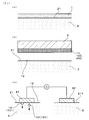
- Example 1 An embodiment of the cosmetic method will be described with reference to FIGS.
- Is performed FIG. 1B).
- FIG. 1C a step of causing an ion introduction current to flow through the skin 2 on which the aqueous solution 12 is disposed and causing the ion introduction component 13 to permeate the skin 2 is performed. The details will be described below.
- the water-based pack agent 1 is applied to the entire surface where the beauty effect is desired.
- the thickness to which the aqueous pack agent 1 is applied is preferably such a thickness that the color of the skin 2 cannot be seen through. The detailed composition of the water-based pack agent 1 will be described later.
- the magnet 3 is brought close to the aqueous pack 1 applied to the skin 2 as shown in FIG. Thereby, the magnetic powder 11 is attracted by the magnet 3 and is attracted and removed from the skin surface 21 by a magnetic force.
- the used aqueous pack 100 and the dirt 200 on the skin 2 attached to the magnetic powder 11 are removed from the skin surface 21 by adsorption.
- the magnet 3 used in this step may be a permanent magnet such as a ferrite magnet or a neodymium magnet, or an electromagnet.
- the aqueous solution 12 containing the iontophoretic component 13 remains on the skin surface 21 without being adsorbed and removed together with the used aqueous pack 100 or the like.
- the aqueous pack agent 1 is adsorbed and removed from the skin surface 21, and the aqueous solution 12 containing the ionized ion introduction component 13 is applied to the skin surface 21.
- the working electrode 41 is brought into contact with the skin surface 21 in a state where the aqueous solution 12 containing the iontophoretic component 13 is applied.
- the counter electrode 42 is brought into contact with the skin surface 211 of the portion where 12 is not applied. In this state, by applying a voltage between the working electrode 41 and the counter electrode 42, an ion introduction current can flow through the skin 2.
- the iontophoretic component 13 used in this example is sodium L-ascorbate-2-phosphate.
- L-ascorbic acid-2-sodium phosphate is ionized in the aqueous solution 12 into L-ascorbic acid-2-phosphate ions 131 and sodium ions. Further, by introducing L-ascorbic acid-2-phosphate ion 131, which is an anion, into the skin by ion introduction, beauty effects such as improvement of skin elasticity, wrinkles and spots, and reduction of pores can be expected. .
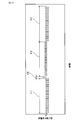
- the ion introduction current of this example includes an ion introduction step in which one polarity ion introduction current (basic waveform F ⁇ b> 1) is supplied to the contact portion between the working electrode 41 and the skin 2 and the other polarity to the contact portion.
- the reset pulse step for flowing the pulse current (basic waveform F2) and the skin care step for flowing the current (basic waveform F3) whose polarity is alternately switched to the contact portion are sequentially repeated.
- the ion introduction step a plurality of pulse voltages are applied between the electrodes while controlling the potential difference between the electrodes so that the working electrode 41 has a lower potential than the counter electrode 42.
- the iontophoretic current becomes a negative pulse current as shown in the basic waveform F1 shown in FIG.
- the ion introduction current flows through the skin 2, the penetration of the L-ascorbic acid-2-phosphate ion 131 into the skin is promoted.
- the reset pulse step a single pulse voltage is applied between the electrodes while controlling the potential difference between the electrodes so that the working electrode 41 is at a higher potential than the counter electrode 42. Thereby, a positive pulse current flows through the skin 2 as in the basic waveform F2 shown in FIG. By performing the reset pulse step in this way, it is possible to neutralize the bias of the charge generated on the skin 2 in the ion introduction step.
- a rectangular wave in which the potential difference between the working electrode 41 and the counter electrode 42 is alternately switched is applied between both electrodes.
- a rectangular wave current in which the positive polarity and the negative polarity are alternately switched flows through the skin 2 as in a basic waveform F3 illustrated in FIG.
- a weak current with alternating polarity flows through the skin 2
- skin cells are activated, lymph flow is improved, blood circulation is promoted, and metabolism is improved.
- Water-based pack 1 The detailed composition of the water-based pack agent 1 applied to the skin 2 is as follows. ⁇ Water 7.92 mass% ⁇ Magnetic powder 11 65% by mass ⁇ Thickener glycerin 17.5% by mass Sodium polyacrylate 0.01% by mass ⁇ Surfactant Polyglyceryl monolaurate 0.2% by mass ⁇ Ion introduction component 13 L-ascorbic acid-2-sodium phosphate 0.1% by mass ⁇ Lubricant, pH adjuster, preservative, etc.
- the preparation methods and characteristics of the magnetic powder 11 used for the water-based pack agent 1 are as follows. ⁇ To a manufacturing method hematite (Fe 2 O 3) powder obtained by pulverizing a solid content to prepare a slurry by adding water so that 55 mass%. Next, after adding 1% by weight of polyvinyl alcohol, 0.9% by weight of carbon black, and 0.5% by weight of polycarboxylic acid salt to the solid content of the obtained slurry, this mixture was added. Water was added to the slurry to prepare a slurry having a solid content of 55% by mass. Subsequently, the slurry obtained using an attritor was stirred for 1 hour. Thereafter, the slurry was granulated into a spherical shape using a spray dryer, and the particle size of the granulated product obtained using a gyro shifter was adjusted.
- the spherical granulated product whose particle size was adjusted was heated at 1320 ° C. for 3 hours to reduce the raw material hematite, and a fired product containing magnetite as a main component was obtained.
- the granulated product was heated in a nitrogen atmosphere using a tunnel electric furnace.
- a classification treatment was performed by using a combination of a gyro shifter and an air classifier to adjust the particle size distribution. Thereafter, magnetic separation was carried out to select particles having a high magnetic susceptibility, and magnetic powder 11 was obtained.
- the magnetic powder 11 obtained as described above was subjected to a surface treatment, and a resin film made of an acrylate copolymer was formed on the surface of the particles constituting the magnetic powder 11.
- the volume average particle diameter was calculated by the following method. First, after adding a 0.2% sodium hexametaphosphate aqueous solution to the magnetic powder 11, the magnetic powder 11 was subjected to ultrasonic treatment for 1 minute using an ultrasonic homogenizer (UH-3C, manufactured by Ultrasonic Industry Co., Ltd.). A dispersion was prepared. This dispersion was introduced into a Microtrac particle size analyzer (manufactured by Nikkiso Co., Ltd., Model 9320-X100) and measured under conditions of a refractive index of 1.81, a temperature of 25 ⁇ 5 ° C., and a humidity of 55 ⁇ 15%, and laser diffraction. The particle size distribution by the scattering method was obtained. From the obtained particle size distribution, the 50% cumulative particle size in the volume distribution mode and under the sieve display was calculated, and this was defined as the volume average particle size (median diameter).
- UH-3C ultrasonic homogenizer
- the volume average particle diameter of the magnetic powder 11 was about 70 ⁇ m.
- the magnetic substance powder 11 was classified by the method according to JIS H2601, using the standard sieve prescribed
- the content of the small particle in the magnetic powder 11 was 6.7% by mass, and the content of the large particle was 0% by mass.
- sample filling amount about 1 g
- sample filling cell inner diameter 7 mm ⁇ ⁇ 0.02 mm
- 4 ⁇ I coil 30 turns
- applied magnetic field 3000 oersted.
- the magnetic material powder 11 had a saturation magnetization of 82 Am 2 / kg, a residual magnetization of 82 Am 2 / kg, and a coercive force of 24 Oe.
- X'PertPRO MPD manufactured by Panalical Co., Ltd. was used as a measuring apparatus. Measurement was performed by continuous scanning at 0.2 ° / sec using a Co tube (CoK ⁇ ray) as an X-ray source and a concentrated optical system and a high-speed detector “X′Celarator” as an optical system. Analysis of the measurement results is performed in the same way as ordinary powder crystal structure analysis using the analysis software “X'PertHighScore”. After identifying the crystal structure, the obtained crystal structure is refined and converted to weight. The abundance ratio was calculated. In calculating the abundance ratio, the abundance ratios of magnetite, hematite, and wustite were calculated using Fe and O as essential elements.
- the X-ray source used for X-ray diffraction measurement can be measured without problems even with a Cu tube, but in the case of a sample containing a large amount of Fe, the background becomes larger than the peak to be measured, so the Co tube Is preferred.
- the optical system may obtain the same result even when the parallel method is used, but measurement with a concentrated optical system is preferable because the X-ray intensity is low and measurement takes time.
- the speed of the continuous scan is not particularly limited, but in order to obtain a sufficient S / N ratio when analyzing the crystal structure, the peak intensity of the (311) plane which is the main peak of magnetite is set to 50000 cps or more. The measurement was performed by setting the sample in the sample cell so that the particles were not oriented in a specific preferred direction.
- the magnetic powder 11 has a chemical component composed of 89.7% by mass of magnetite, 4.1% by mass of hematite, and 6.2% by mass of wustite.
- ⁇ Test method> The right half of the subject's face was used as the treatment site, and the treatment was performed on the treatment site by the following method once every three days.
- the aqueous pack 1 was applied only to the treatment area and left for 3 minutes.
- the magnet 3 was brought close to the aqueous pack 1 applied to the skin 2, and the magnetic powder 11 and the used aqueous pack 1 were adsorbed and removed from the skin 2.
- the left half of the subject's face was treated as a control unit according to the following procedure.
- an oil-based pack agent containing 65% by mass of magnetic powder 11 was applied to the control unit and allowed to stand for 3 minutes. After 3 minutes, the magnet 3 was brought close to the oil-based pack applied to the skin 2, and the magnetic powder 11 and the used oil-based pack were removed from the skin 2 by adsorption. After adsorption removal, a cosmetic solution containing L-ascorbic acid-2-sodium phosphate was applied to the control part, and an iontophoretic current was passed for about 5 minutes in the same manner as in the treatment part.
- oil-based pack agent ⁇ Excipient Triethylhexanoin 21.4% by mass Vaseline 3.5% by mass ⁇ Magnetic powder 11 65% by mass -Surfactant Glyceryl stearate 1.1% by mass Polyglyceryl laurate-10 0.7% by mass ⁇ Emulsifier Cetanol 1.8% by mass Sorbitan stearate 1.8% by mass ⁇ Lubricant, preservative, etc.
- Table 1 shows the skin elasticity at the start of the test, the skin elasticity at the completion of the test, and the amount of change in skin elasticity for each subject.
- FIG. 3 is a graph showing an average value of the skin elasticity of the entire subject at the start of the test and an average value of the skin elasticity of the entire subject at the completion of the test. The vertical axis in FIG. 3 is the average value of skin elasticity.
- the skin elasticity of the treatment area improved after the test in almost all the subjects, and the skin elasticity tended to improve over time.
- the skin elasticity at the completion of the test increased by an average of 14.5% compared to that at the start of the test. This increase in skin elasticity was statistically significant at the 1% level.
- the skin elasticity of the control part was improved by only half of the subjects after the test, and there was no tendency for the skin elasticity to improve over time.
- the skin elasticity at the completion of the test increased by an average of 0.4% compared to that at the start of the test. This increase in skin elasticity was not recognized as a statistically significant difference. From the above results, it can be seen that the beauty effect that the skin elasticity is improved is obtained by the beauty method.
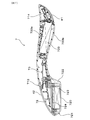
- the beauty device 7 includes a substantially rod-shaped main body 71, a suction head 72 disposed at one end of the main body 71, and a working electrode 41 disposed at the other end of the main body 71. It has.
- the adsorption head unit 72 includes a magnetic force generation surface 720 for adsorbing and removing the aqueous pack agent 1 applied to the skin 2 by magnetic force.
- the beauty tool 7 is configured to allow an ion introduction current to flow through the contact portion in a state where the working electrode 41 is in contact with the skin 2.
- a power supply unit 733 for supplying power to the working electrode 41 and a control unit 73 for controlling a current flowing through the contact unit are built in the main body 71.
- one end of the main body 71 in the beauty tool 7 is configured to form an annular current path between the power source 733 and the human body together with the suction head 72 and the working electrode 41. And a counter electrode 42.
- the other end of the main body 71 is provided with a working electrode 41.
- the side where the working electrode 41 in the longitudinal direction of the main body 71 is provided may be referred to as the front, and the side where the suction head portion 72 is provided may be referred to as the rear.
- the magnetic force generation surface 720 side may be referred to as the lower side, and the opposite side may be referred to as the upper side.
- the direction orthogonal to both the front-back direction and the up-down direction may be called a side.
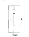
- the main body 71 has a substantially arc shape when viewed from the side, and is curved so that a substantially central portion in the front-rear direction (longitudinal direction) is positioned above both end portions. Is formed. As shown in FIGS. 5 and 6, the two ends of the main body 71 in the front-rear direction have a substantially arc shape when viewed from the top-bottom direction. Further, the central portion in the longitudinal direction of the main body 71 is formed narrower than both ends when viewed from the up-down direction.
- the suction head portion 72 disposed at the rear end portion of the main body portion 71 has a bulging portion 721 that bulges downward from the main body portion 71. Further, the bulging portion 721 has a magnetic force generation surface 720 on the top surface portion.
- the bulging portion 721 has a magnetic force generation surface 720 that is a flat surface, and a head side wall 722 that extends from the outer periphery of the magnetic force generation surface 720.
- the magnetic force generation surface 720 has a substantially elliptical shape when viewed from below, and is arranged with its major axis directed in the front-rear direction (longitudinal direction).
- the head side wall 722 gradually increases in diameter from the outer peripheral edge of the magnetic force generation surface 720 upward.
- the magnetic force generation surface 720 and the head side wall 722 are connected by a gently curved surface.
- a substantially cylindrical permanent magnet 723 is built in the bulging portion 721 of the suction head portion 72.
- the permanent magnet 723 is disposed inside the bulging portion 721 such that one magnetic pole surface and the inner wall surface of the magnetic force generation surface 720 are in contact with each other.
- the other magnetic pole surface of the permanent magnet 723 is covered with a yoke material 724 made of a soft magnetic material.
- the beauty tool 7 is configured such that the magnetic force generated from the permanent magnet 723 acts more strongly downward.
- the permanent magnet 723 of this example is a neodymium magnet magnetized in the axial direction.
- the magnetic flux density measured at a point 20 mm downward from the center of the magnetic force generation surface 720 was 43 mT.
- the main body 71 has a counter electrode 42 on the side opposite to the magnetic force generation surface 720 (upward).
- the working electrode 41 is disposed such that the electrode surface faces the magnetic force generation surface 720 side (downward).
- the working electrode 41 and the counter electrode 42 are formed so that the width in the lateral direction is narrower than the maximum width of the main body 71.
- a power supply unit 733, a control unit 73, an LED indicator 713, and a vibration motor 714 are disposed inside the main body unit 71.
- the power supply unit 733 is disposed between the center in the longitudinal direction and the working electrode 41 inside the main body 71, and is configured to accommodate the battery 733 a in the space inside the main body 71. 6 and 7, the battery 733a is held in the main body 71 by attaching a lid 733b that can be attached to and detached from the main body 71. As shown in FIG.
- the control unit 73 is disposed on the suction head unit 72 side from the longitudinal center of the main body unit 71. Further, the LED indicator 713 is disposed at a substantially central portion in the longitudinal direction in the main body 71 as shown in FIGS. 5 and 7. The LED indicator 713 is configured to emit light upward when an ion introduction current flows from the working electrode 41 to the skin 2.
- the vibration motor 714 is disposed at the end of the main body 71 on the working electrode 41 side. The vibration motor 714 is configured to generate vibration when the ion introduction current flows from the working electrode 41 to the skin 2.
- the power supply unit 733 is connected to each of the control microcomputer 730 and the voltage application unit 731, the LED indicator 713, and the vibration motor 714 in the control unit 73, and supplies operating power to these units. ing.
- the control unit 73 includes a control microcomputer 730, a voltage application unit 731, and a reflux unit 732.
- the control unit 73 is connected to the power supply unit 733, the working electrode 41, the counter electrode 42, the LED indicator 713, and the vibration motor 714, and is configured to be able to control operations of these units.
- the control microcomputer 730 has a function of inputting and outputting a signal for controlling the operation of each unit.
- the voltage application unit 731 has a function of applying a voltage between the working electrode 41 and the counter electrode 42.
- the reflux unit 732 has a function of taking a current flowing through the human body from the working electrode 41 or the counter electrode 42 and refluxing the current to the power source unit 733.
- the control microcomputer 730 and the voltage application unit 731 are connected to each other so that a voltage control signal and a current value selection signal described later can be transmitted.
- the reflux unit 732 is disposed between the voltage application unit 731 and the ground unit 731 c connected to the negative pole of the power supply unit 733.
- the reflux unit 732 is connected to an ADC (Analog to Digital Converter) 730a described later of the control microcomputer 730.
- the control unit 73 is configured to be able to input the potential difference in the reflux unit 732 to the control microcomputer 730.
- the control microcomputer 730 includes an ADC 730a, a calculation unit 730b, a signal output unit 730c, and a delay timer 730d.
- the ADC 730 a has a function of digitizing the potential difference in the reflux unit 732.
- the calculation unit 730b has a function of determining whether the working electrode 41 and the counter electrode 42 are in contact with the human body.
- the signal output unit 730c has a function of controlling the current that flows from the working electrode 41 to the skin surface 21 where a cosmetic effect is desired.
- the ADC 730 a is connected to the reflux unit 732 of the control unit 73 and is configured to digitize the potential difference of the reflux unit 732 with respect to the potential of the ground unit 731 c (hereinafter, the potential of the ground unit 731 c is referred to as “ground potential”). Yes.
- the value of the potential difference digitized by the ADC 730 a is transmitted to the arithmetic unit 730 b in the control microcomputer 730.
- the calculation unit 730b compares the potential difference value input from the ADC 730a with a predetermined threshold value.
- the calculation unit 730b determines that at least one of the working electrode 41 and the counter electrode 42 is not in contact with the human body when the value of the potential difference is less than the predetermined threshold, and the value of the potential difference is the predetermined value. It is configured to determine that both the working electrode 41 and the counter electrode 42 are in contact with the human body when it is equal to or greater than the threshold value.
- the calculation unit 730b is configured to be able to control a signal output from the signal output unit 730c based on both the determination result and the preset operation flow illustrated in FIGS. 9 and 10. Details of the operation flow will be described later.
- the signal output unit 730c is configured to output a voltage control signal and a current value selection signal to the voltage application unit 731 in response to the control signal from the calculation unit 730b.
- the voltage control signal is input to a polarity inversion circuit 731a (to be described later) in the voltage application unit 731 and controls the on / off and polarity of the voltage applied between the working electrode 41 and the counter electrode 42.
- the current value selection signal is input to a constant current circuit 731b described later in the voltage application unit 731 and controls a current value flowing between the working electrode 41 and the counter electrode 42.
- the signal output unit 730c is also connected to the LED indicator 713 and the vibration motor 714, respectively.
- the signal output unit 730c drives each of the LED indicator 713 and the vibration motor 714 when it is determined that both the working electrode 41 and the counter electrode 42 are in contact with the human body as a result of the determination in the calculation unit 730b.
- the drive signal to be output is configured to be output.
- the delay timer 730d is activated by the calculation unit 730b when it is determined that at least one of the working electrode 41 and the counter electrode 42 is not in contact with the human body as a result of the determination in the calculation unit 730b.
- the delay timer 730d has a function of stopping the operation of the calculation unit 730b for a predetermined time. Thereby, in the beauty tool 7, the operation of each unit is stopped along with the operation stop of the calculation unit 730 b until the predetermined time elapses after the delay timer 730 d is activated.
- the delay timer 730d is configured to restart the operation of the calculation unit 730b after the predetermined time has elapsed.
- the voltage application unit 731 includes a polarity inversion circuit 731a and a constant current circuit 731b, and both are connected to each other.
- the polarity inversion circuit 731a is connected to the signal output unit 730c of the control microcomputer 730.
- the polarity inversion circuit 731 a is connected to each of the working electrode 41 and the counter electrode 42.
- the polarity inverting circuit 731a is configured to be able to control the potential difference between the working electrode 41 and the counter electrode 42 based on the voltage control signal output from the signal output unit 730c.
- the constant current circuit 731b has a function of keeping the current flowing between the working electrode 41 and the counter electrode 42 at a constant value.
- the constant current circuit 731b is connected to the signal output unit 730c of the control microcomputer 730.
- the constant current circuit 731b is configured to be able to set the current flowing between the working electrode 41 and the counter electrode 42 in two stages based on the current value selection signal output from the signal output unit 730c.
- the magnitude of the current is set in two stages, that is, an ion introduction level and a skin care level having a current value smaller than the ion introduction level.
- the ion introduction level is applied during execution of an ion introduction step S8 and a reset pulse step S9 described later, and the skin care level is applied during execution of a skin care step S11.
- the reflux unit 732 includes a resistor 732a connected between the voltage application unit 731 and the ground unit 731c.
- the current taken from the voltage application unit 731 side flows in the resistor 732a toward the grounding unit 731c, and is returned to the negative pole of the power supply unit 733 via the grounding unit 731c.
- the voltage application unit 731 and the resistor 732 a in the reflux unit 732 are connected to the ADC 730 a of the control microcomputer 730.
- the ADC 730a is configured such that a potential difference with respect to the ground potential at a point between the voltage application unit 731 and the resistor 732a is input.
- step S1 the control microcomputer 730 outputs a current value selection signal to the constant current circuit 731b, and sets the current value to the ion introduction level.
- control microcomputer 730 performs step S2 of waiting for the elapse of the predetermined time by the delay timer 730d.
- the delay timer 730d of this example can appropriately set the predetermined time in the range of 50 to 1000 milliseconds.
- the control microcomputer 730 performs step S3 of supplying operating power from the power supply unit 733 to the voltage application unit 731 and outputs a voltage control signal from the signal output unit 730c after step S2. Thereby, the control microcomputer 730 applies a pulse voltage once between both electrodes while controlling the potential difference between both electrodes so that the working electrode 41 has a low potential with respect to the counter electrode 42. In this way, step S4 in which the pulse voltage is applied once between the working electrode 41 and the counter electrode 42 is performed. In this example, the value of the pulse voltage in step S4 is 5V.
- step S5 of measuring the potential difference in the reflux unit 732 is performed.
- step S5 when both the working electrode 41 and the counter electrode 42 are in contact with the skin 2, a pulse current based on the pulse voltage flows from the counter electrode 42 to the working electrode 41 through the human body.
- the pulse current is taken into the control unit 73 from the working electrode 41, and a potential difference is generated between both ends of the resistor 732a in the reflux unit 732 as a waveform F4 illustrated in FIG.
- the potential difference generated between both ends of the resistor 732a that is, the potential difference in the reflux unit 732 with reference to the ground potential is input to the ADC 730a of the control microcomputer 730, and the value is measured.
- the control microcomputer 730 determines, in the calculation unit 730b, the contact state between the working electrode 41 and the counter electrode 42 and the human body based on the comparison result between the potential difference and a predetermined threshold value L (see FIG. 11). I do. If the potential difference measured in step S5 is less than the threshold value L, the control microcomputer 730 determines that at least one of the working electrode 41 or the counter electrode 42 is not in contact with the human body (step S6, “No”). . In this case, the control microcomputer 730 returns to step S2 and starts the delay timer 730d. The control microcomputer 730 repeats steps S2 to S6 while it is determined in step S6 that at least one of the working electrode 41 and the counter electrode 42 is not in contact with the human body. In this example, the threshold value L can be appropriately set between 50 and 200 mV.
- step S6 when the potential difference in the reflux unit 732 with reference to the ground potential is greater than or equal to the threshold L in step S6, the control microcomputer 730 determines that both the working electrode 41 and the counter electrode 42 are It determines with contacting (step S6, "Yes"). In this case, as shown in FIG. 9, the control microcomputer 730 outputs a current value selection signal to the constant current circuit 731b, and performs step S7 of setting the current value to the ion introduction level. After step S7, the control microcomputer 730 sends a voltage control signal to the voltage application unit 731 so that an ion introduction current flows from the working electrode 41 to the skin 2.
- the ion introduction current includes an ion introduction step S8 in which a current of one polarity (FIG. 2, F1) is passed to the contact portion between the working electrode 41 and the skin 2, and a pulse current of the other polarity to the contact portion.
- a reset pulse step S9 for flowing (FIG. 2, F2) and a skin care step S11 for flowing a current (FIG. 2, F3) whose polarity is alternately switched to the contact portion are sequentially repeated.
- the waveform of the iontophoretic current flowing in the skin 2 repeats the basic waveforms F1 to F3 shown in FIG.
- control microcomputer 730 outputs drive signals from the signal output unit 730c to the LED indicator 713 and the vibration motor 714 while the ion introduction current flows through the skin 2 (FIG. 10, step T1). Accordingly, the LED indicator 713 and the vibration motor 714 are driven while both the working electrode 41 and the counter electrode 42 are in contact with the human body.
- the control microcomputer 730 controls the potential difference between the two electrodes so that the working electrode 41 is at a low potential with respect to the counter electrode 42, and applies a pulse voltage between the two electrodes. Apply multiple times. Thereby, the working electrode 41 can flow a negative pulse current to the skin 2 a plurality of times as in the basic waveform F1 shown in FIG.
- the control microcomputer 730 applies a pulse voltage once between both electrodes while controlling the potential difference between both electrodes so that the working electrode 41 becomes a high potential with respect to the counter electrode. Thereby, the working electrode 41 can flow a positive pulse current to the skin 2 as in the basic waveform F2 shown in FIG.
- control microcomputer 730 outputs a current value selection signal to the constant current circuit 731b, and performs step S10 for setting the current value to the skin care level.
- the control microcomputer 730 performs the skin care step S11 after performing step S10.
- the control microcomputer 730 applies a rectangular wave between the electrodes in which the level of the potential difference of the working electrode 41 with respect to the counter electrode 42 is alternately switched.
- the working electrode 41 can flow a rectangular wave current in which the positive polarity and the negative polarity are alternately switched to the skin 2 as in the basic waveform F3 illustrated in FIG.
- the control microcomputer 730 uses the pulse of the ion introduction current flowing through the skin 2 in parallel with steps S7 to S11, so that the working electrode 41 and the counter electrode 42 are in contact with the human body. It has a skin detection function to make the determination. That is, the control microcomputer 730 uses the pulses that flow to the skin 2 in the ion introduction step S8, the reset pulse step S9, and the skin care step S11 to return to the ground potential generated due to the pulse current as in step S5.
- the unit 732 is configured to perform the potential difference measurement T2.
- step T3 for determining the contact state between the working electrode 41 and the counter electrode 42 and the human body based on the result of the potential difference measurement of the reflux unit 732 described above.
- the determination of the contact state between the working electrode 41 and the counter electrode 42 and the human body in step T3 may be performed based on the result of potential difference measurement for one pulse current, or the results of potential difference measurement for a plurality of pulse currents are combined. You may go.
- the pulse current used for determination of the contact state mentioned above can be suitably selected from the pulse current in each step of the ion introduction step S8, the reset pulse step S9, and the skin care step S11.
- the determination of the contact state in step T3 is performed by checking whether the potential difference between both ends of the resistor 732a due to the pulse current (FIG. 2, F2) in the reset pulse step S9 is continuously lower than the threshold value L a predetermined number of times. Implemented on the basis of no.
- the control microcomputer 730 of the present example causes the working electrode 41 when the potential difference caused by the pulse current (FIG. 2, F2) is continuously less than the threshold value L for a predetermined number of times (step T3, “Yes”).
- control microcomputer 730 stops generating the ion introduction current and stops outputting the drive signal to the LED indicator 713 and the vibration motor 714 (step T4).
- the control microcomputer 730 is configured to repeat steps S2 to S6 shown in FIG. 9 after step T4.
- step T3, “No” the control microcomputer 730 is connected to both the working electrode 41 and the counter electrode 42. It is determined that the human body is in contact.
- the control microcomputer 730 repeatedly executes steps S7 to S11 shown in FIG. 9 while it is determined in step T3 that both the working electrode 41 and the counter electrode 42 are in contact with the human body.
- a removable cover member can be attached to the magnetic force generation surface 720 in advance.
- various shapes and materials can be used without being limited in shape and material.
- a sheet-shaped cotton is wound around the suction head portion 72 (not shown).
- the dirt 200 and the like of the skin 2 together with the magnetic powder 11 are removed from the skin surface 21 and are adsorbed by the adsorption head unit 72.
- the aqueous solution 12 containing the iontophoretic component 13 is applied to the skin 2.
- the used aqueous pack 1 adsorbed by the adsorption head unit 72 can be peeled off from the magnetic force generating surface 720 together with the cover member and discarded.
- the user After removing the used aqueous pack 100 and the like from the skin 2 in this way, the user changes the body 71 so that the working electrode 41 protrudes from the hand and the counter electrode 42 contacts the hand. Grab. Then, the working electrode 41 is brought into contact with the skin surface 21 as shown in FIG. Thereby, an iontophoretic current consisting of repetition of the basic waveforms F1 to F3 shown in FIG. 2 flows through the contact portion between the working electrode 41 and the skin 2.
- the working electrode 41 functions as a cathode and the counter electrode 42 functions as an anode, and a negative current flows through the skin surface 21 in contact with the working electrode 41.
- the beauty tool 7 can penetrate the L-ascorbic acid-2-phosphate ion 131, which is an anion, into the skin.
- the beauty tool 7 has an adsorption head portion 72 for adsorbing and removing the aqueous pack 1 by magnetic force. Therefore, as shown in FIG. 12, when the user holds the main body 71 and brings the suction head portion 72 close to the skin surface 21 to which the aqueous pack agent 1 is applied, the aqueous pack agent 1 is attracted by the magnetic force by the magnetic force. 72 is adsorbed. As a result, the beauty tool 7 can easily remove the used aqueous pack 1.
- the beauty tool 7 has a working electrode 41 for flowing an iontophoretic current through the contact portion in a state of being in contact with the skin 2. Therefore, a user who has previously applied a charged cosmetic component to the skin 2 causes the working electrode 41 to contact the skin 2 and cause an iontophoretic current to flow as described above. Makes it easier to move. As a result, the beauty tool 7 facilitates the penetration of the beauty component and facilitates promptly exerting the beauty effect.
- the beauty instrument 7 has both the suction head portion 72 and the working electrode 41. Therefore, as described above, the beauty tool 7 removes both dirt and waste from the skin 2 with the water-based pack agent 1 and works to permeate the charged cosmetic component into the skin with the iontophoretic current. Can be performed with one instrument. As a result, the user does not have to prepare separate instruments for the two operations and use them separately.
- the suction head portion 72 has a magnetic force generation surface 720 in a direction (downward) substantially orthogonal to the longitudinal direction of the main body portion 71. Therefore, the user can easily point the magnetic force generating surface 720 toward the skin 2 to which the aqueous pack agent 1 is applied, as shown in FIG. As a result, the beauty tool 7 is more convenient for the user.
- the main body 71 has the counter electrode 42 on the side opposite to the magnetic force generating surface 720 (upward), and as shown in FIG. 6, the working electrode 41 is arranged to face downward.
- the beauty tool 7 when the beauty tool 7 is placed on a desk or the like, the possibility that the working electrode 41 and the counter electrode 42 are conducted through the placement surface can be reduced, and the power consumption of the beauty tool 7 can be reduced. It becomes easy to reduce.
- the beauty tool 7 can efficiently flow the iontophoretic current through the human body. As a result, the beauty tool 7 can further improve the beauty effect.
- the control unit 73 applies a pulse voltage to the working electrode 41, and measures the electrical characteristic value in the control unit 73 using the pulse voltage, Based on the electrical characteristic value, the means for determining whether or not the working electrode 41 and the counter electrode 42 are in contact with the human body, and the determination that both the working electrode 41 and the counter electrode 42 are in contact with the human body If it is determined that at least one of the working electrode 41 and the counter electrode 42 is not in contact with the human body, a delay timer is provided. After the elapse of a predetermined time by 730d, the measurement of the electrical characteristic value and the determination are performed again.
- the beauty tool 7 can flow an ion introduction current to the contact portion when the working electrode 41 and the counter electrode 42 come into contact with the human body without requiring a separate switch operation.
- the user can easily grasp the cosmetic component simply by holding the counter electrode 42 side of the main body 71 and bringing the counter electrode 42 into contact with the hand and bringing the working electrode 41 into contact with the portion where the cosmetic effect is desired.
- the penetration promotion effect can be obtained.
- the beauty tool 7 can reduce the frequency of executing the measurement of the electrical characteristic value and the determination by operating the delay timer 730d as described above. As a result, the beauty tool 7 can reduce power consumption in a standby state, that is, in a state where at least one of the working electrode 41 or the counter electrode 42 is not in contact with the human body.
- the control unit 73 includes a reflux unit 732 that takes in the current flowing through the human body and returns it to the power supply unit 733, and has a reflux unit 732 for the ground potential as an electrical characteristic value. And when the potential difference is equal to or greater than a predetermined threshold value, it is determined that both the working electrode 41 and the counter electrode 42 are in contact with the human body. Therefore, the control unit 73 can easily simplify the circuit configuration as described above, and can improve the determination accuracy of whether or not the working electrode 41 and the counter electrode 42 are in contact with the human body. Can do.
- the ion introduction current includes an ion introduction step S8 in which a current of one polarity (FIG. 2, F1) is supplied to the contact portion, and a pulse current of the other polarity (FIG. 2, FIG. 2) to the contact portion. F2) is reset pulse step S9, and skin care step S11 is configured to sequentially repeat a current (FIG. 2, F3) whose polarity is alternately switched to the contact portion. Therefore, as described above, the beauty device 7 can be expected to further improve the beauty effect due to the synergistic effect of the effect of promoting penetration of the beauty components into the skin and the activation effect of the skin 2.
- the beauty tool 7 has a vibration motor 714 at the end on the working electrode 41 side, and is configured such that the vibration motor 714 is driven while an ion introduction current flows through the skin 2. Therefore, due to the vibration generated from the vibration motor 714, the contact portion between the working electrode 41 and the skin 2 and its peripheral portion have effects such as improved lymph flow, blood circulation, and improved metabolism. May be obtained. As a result, the beauty tool 7 can further improve the beauty effect that can be experienced.
- the beauty tool 7 can improve the convenience in the case of continuously performing the work of removing dirt and waste in the skin and the work of infiltrating the cosmetic ingredients into the skin. Become.
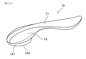
- Example 2 while showing the example of the beauty instrument 7 which has the adsorption
- the work of adsorbing the magnetic powder 11 and the ion introduction can be performed using different instruments. That is, for example, as shown in FIG. 14 and FIG. 15, the work of adsorbing the magnetic powder 11 is performed by using a beauty tool 7 b having only the adsorption head unit 72 without providing the working electrode 41, the control unit 73, and the like. It can be carried out.
- the same reference numerals as those used in the second embodiment indicate the same components as in the second embodiment.
- the beauty instrument 7 is not provided with the suction head portion 72, and the configuration including the working electrode 41, the control portion 73, and the like enables ion introduction.
- the form of the beauty tool 7 is not limited to the shape shown in Example 2, and can take various forms.
- the main body 71 can be formed in a spherical shape or a cylindrical shape.
Abstract
Description
肌に塗布した上記水系パック剤中の上記磁性体粉に磁力を作用させ、肌表面に上記イオン導入成分の水溶液を残しつつ肌表面から上記磁性体粉を吸着除去するステップと、
上記水溶液が配された肌にイオン導入電流を流して上記イオン導入成分を肌内部へ浸透させるステップとを有することを特徴とする美容方法にある。
上記美容方法の実施例について、図1~図3を用いて説明する。本例の美容方法においては、まず、水と、強磁性を示すフェライトを主成分とする磁性体粉11と、増粘剤と、電荷を帯びたイオン導入成分13とを含有する水系パック剤1を肌2に塗布するステップが実施される(図1(a))。次いで、肌2に塗布した水系パック剤1中の磁性体粉11に磁力を作用させ、肌表面21にイオン導入成分13の水溶液12を残しつつ肌表面21から磁性体粉11を吸着除去するステップが実施される(図1(b))。そして、水溶液12が配された肌2にイオン導入電流を流してイオン導入成分13を肌2へ浸透させるステップが実施される(図1(c))。以下、詳説する。
20歳以上60歳未満の日本人女性8名を対象とした。
肌2に塗布する水系パック剤1の詳細な組成は、以下の通りである。
・水 7.92質量%
・磁性体粉11 65質量%
・増粘剤
グリセリン 17.5質量%
ポリアクリル酸ナトリウム 0.01質量%
・界面活性剤
モノラウリン酸ポリグリセリル 0.2質量%
・イオン導入成分13
L-アスコルビン酸-2-リン酸ナトリウム 0.1質量%
・潤滑剤、pH調整剤、保存料等 残部
また、水系パック剤1に用いた磁性体粉11の作製方法及び特性は以下の通りである。
・作製方法
ヘマタイト(Fe2O3)を粉砕した粉末に対し、固形分が55質量%となるように水を加えてスラリーを調製した。次いで、得られたスラリーの固形分に対して1質量%のポリビニルアルコールと、0.9質量%のカーボンブラックと、0.5質量%のポリカルボン酸塩とをスラリーに加えた後、この混合物に水を加えて固形分が55質量%のスラリーを調製した。次いで、アトライターを用いて得られたスラリーを1時間攪拌した。その後、スプレードライヤーを用いてスラリーを球状に造粒し、ジャイロシフターを用いて得られた造粒物の粒度調整を行った。
体積平均粒径の算出は、以下の方法により行った。まず、磁性体粉11に0.2%ヘキサメタリン酸ナトリウム水溶液を加えた後、ウルトラソニックホモジナイザー(超音波工業社製、UH-3C)を用いて1分間の超音波処理を行って磁性体粉11の分散液を調製した。この分散液をマイクロトラック粒度分析計(日機装株式会社製、Model9320-X100)に導入し、屈折率1.81、温度25±5℃、湿度55±15%の条件下で測定を行い、レーザー回折散乱法による粒径分布を得た。得られた粒径分布から、体積分布モード、ふるい下表示での累積50%粒子径を算出し、これを体積平均粒径(メジアン径)とした。
JIS Z 8801に規定される標準ふるいを用いて、JIS H 2601に準じた方法により磁性体粉11の分級を行った。これにより、呼び寸法37μm(400メッシュ)の標準ふるいを通過した粒子(小径粒子)の含有量及び呼び寸法105μm(145メッシュ)の標準ふるいを通過しなかった粒子(大径粒子)の含有量を測定した。
磁気特性の測定は、積分型B-Hトレーサー((株)理研電子製、BHU-60型)を使用して以下の手順で行った。まず、電磁石間に磁場測定用Hコイル及び磁化測定用4πIコイルを入れ、磁性体粉11を4πIコイル内に入れる。次いで、電磁石の電流を変化させ磁場Hを変化させたHコイル及び4πIコイルの出力をそれぞれ積分し、X軸にH出力をとり、Y軸に4πIコイルの出力をとったヒステリシスループを記録紙に描く。このヒステリシスループから飽和磁化、残留磁化及び保持力を算出した。なお、ヒステリシスループの測定条件は、試料充填量:約1g、試料充填セル:内径7mmφ±0.02mm、高さ10mm±0.1mm、4πIコイル:巻数30回、印加磁場:3000エルステッドとした。
X線回折法を用いて、マグネタイト(Fe3O4)、ヘマタイト(Fe2O3)及びウスタイト(FeO)の組成比を以下の方法で算出した。
被験者の顔の右半分を施術部とし、3日に1回の間隔で以下の方法による施術を施術部に対して行った。まず、クレンジング及び洗顔を行った後、施術部のみに水系パック剤1を塗布し、3分間放置した。3分経過後、肌2に塗布した水系パック剤1に磁石3を接近させ、磁性体粉11及び使用済みの水系パック剤1を肌2から吸着除去した。吸着除去の後、施術部へ図2に示すイオン導入電流を5分程度流した。以上により施術を完了した。
[油系パック剤]
・賦形剤
トリエチルヘキサノイン 21.4質量%
ワセリン 3.5質量%
・磁性体粉11 65質量%
・界面活性剤
ステアリン酸グリセリル 1.1質量%
ラウリン酸ポリグリセリル-10 0.7質量%
・乳化剤
セタノール 1.8質量%
ステアリン酸ソルビタン 1.8質量%
・潤滑剤、保存料等 残部
・イオン導入成分13
L-アスコルビン酸-2-リン酸ナトリウム 0.1質量%
クエン酸ナトリウム 0.08質量%
クエン酸 0.02質量%
・ブチレングリコール 5質量%
・グリセリン 3質量%
・ジプロピレングリコール 2質量%
・水、増粘剤、保存料等 残部
試験開始時及び試験完了時(4週間経過時点)の各時点における肌弾力を、皮膚粘弾性測定装置(Courage+Khazaka社製「Cutometer(登録商標)」)を用いて測定した。測定は、施術部の頬部及びコントロール部の頬部の各々について5回ずつ行い、5回の平均を算出した。なお、肌弾力の測定は、温度22±2℃、相対湿度50±3%RHの環境下において測定部位を露出させた状態を10分間継続し、測定部を上記環境に馴化させた後に行った。

上記美容方法に使用する美容器具の例について、図4~図13を用いて説明する。美容器具7は、図4に示すように、略棒状の本体部71と、本体部71の一端に配置された吸着ヘッド部72と、本体部71の他端側に配置された作用電極41とを備えている。吸着ヘッド部72は、図6及び図7に示すように、肌2に塗布された水系パック剤1を磁力により吸着除去するための磁力発生面720を備えている。美容器具7は、図13に示すように、作用電極41を肌2に接触させた状態で、当該接触部にイオン導入電流を流すことが可能に構成されている。本体部71内には、図7に示すように、作用電極41に電力を供給するための電源部733と、上記接触部に流す電流を制御するための制御部73とが内蔵されている。
Claims (11)
- 水と、磁性体粉と、増粘剤と、電荷を帯びたイオン導入成分とを含有する水系パック剤を肌に塗布するステップと、
肌に塗布した上記水系パック剤中の上記磁性体粉に磁力を作用させ、肌表面に上記イオン導入成分の水溶液を残しつつ肌表面から上記磁性体粉を吸着除去するステップと、
上記水溶液が配された肌にイオン導入電流を流して上記イオン導入成分を肌内部へ浸透させるステップとを有することを特徴とする美容方法。 - 5~73質量%の上記水と、15~80質量%の上記磁性体粉とを含有する上記水系パック剤を用いることを特徴とする請求項1に記載の美容方法。
- 上記増粘剤として10~45質量%のグリセリンを含むことを特徴とする請求項1または2に記載の美容方法。
- 上記水系パック剤の25℃における導電率が20μS/cm以上であることを特徴とする請求項1~3のいずれか1項に記載の美容方法。
- 水溶性溶剤と、磁性体粉と、増粘剤と、電離してイオン導入成分を生じさせる成分とを含有する水系パック剤を肌に塗布するステップと、
肌に塗布した上記水系パック剤中の上記磁性体粉に磁力を作用させ、肌表面に上記イオン導入成分を残しつつ肌表面から上記磁性体粉を吸着除去するステップと、
肌にイオン導入電流を流して上記イオン導入成分を肌内部へ浸透させるステップとを有することを特徴とする美容方法。 - 上記水系パック剤の粘度は9000mPa・s以上であることを特徴とする請求項1~5のいずれか1項に記載の美容方法。
- 上記磁性体粉は、レーザー回折散乱法により得られる粒径分布から求めた体積平均粒径が50~75μmであり、粒径が37μm未満である粒子の含有量が15質量%以下であり、かつ、粒径が105μm以上である粒子の含有量が5質量%以下であることを特徴とする請求項1~6のいずれか1項に記載の美容方法。
- 上記磁性体粉の飽和磁化が80Am2/kg以上であることを特徴とする請求項1~7のいずれか1項に記載の美容方法。
- 上記磁性体粉は強磁性を示す金属より構成されており、上記磁性体粉を構成する粒子の表面には酸化防止膜が形成されていることを特徴とする請求項1~8のいずれか1項に記載の美容方法。
- 上記磁性体粉の主成分は強磁性を示すフェライトであることを特徴とする請求項1~8のいずれか1項に記載の美容方法。
- 上記磁性体粉は、80質量%以上のマグネタイトと、ウスタイト、ヘマタイト及び不可避不純物からなる残部とからなる化学成分を有することを特徴とする請求項10に記載の美容方法。
Priority Applications (8)
| Application Number | Priority Date | Filing Date | Title |
|---|---|---|---|
| RU2016130042A RU2677920C2 (ru) | 2013-12-25 | 2014-11-04 | Способ косметического ухода |
| CA2932852A CA2932852A1 (en) | 2013-12-25 | 2014-11-04 | Beauty care method |
| AU2014371743A AU2014371743A1 (en) | 2013-12-25 | 2014-11-04 | Cosmetic method |
| US15/106,933 US10548822B2 (en) | 2013-12-25 | 2014-11-04 | Beauty care method |
| CN201480071088.4A CN106102824B (zh) | 2013-12-25 | 2014-11-04 | 美容方法 |
| KR1020167020002A KR20160103049A (ko) | 2013-12-25 | 2014-11-04 | 미용 방법 |
| SG11201604439UA SG11201604439UA (en) | 2013-12-25 | 2014-11-04 | Beauty care method |
| EP14875841.0A EP3088042A4 (en) | 2013-12-25 | 2014-11-04 | Cosmetic method |
Applications Claiming Priority (4)
| Application Number | Priority Date | Filing Date | Title |
|---|---|---|---|
| JP2013266211 | 2013-12-25 | ||
| JP2013-266211 | 2013-12-25 | ||
| JP2014-023921 | 2014-02-11 | ||
| JP2014023921A JP6522281B2 (ja) | 2013-12-25 | 2014-02-11 | 美容器具の作動方法 |
Publications (1)
| Publication Number | Publication Date |
|---|---|
| WO2015098295A1 true WO2015098295A1 (ja) | 2015-07-02 |
Family
ID=53478173
Family Applications (1)
| Application Number | Title | Priority Date | Filing Date |
|---|---|---|---|
| PCT/JP2014/079275 WO2015098295A1 (ja) | 2013-12-25 | 2014-11-04 | 美容方法 |
Country Status (11)
| Country | Link |
|---|---|
| US (1) | US10548822B2 (ja) |
| EP (1) | EP3088042A4 (ja) |
| JP (1) | JP6522281B2 (ja) |
| KR (1) | KR20160103049A (ja) |
| CN (1) | CN106102824B (ja) |
| AU (1) | AU2014371743A1 (ja) |
| CA (1) | CA2932852A1 (ja) |
| RU (1) | RU2677920C2 (ja) |
| SG (2) | SG10201804768VA (ja) |
| TW (1) | TW201531260A (ja) |
| WO (1) | WO2015098295A1 (ja) |
Families Citing this family (7)
| Publication number | Priority date | Publication date | Assignee | Title |
|---|---|---|---|---|
| RU2680403C1 (ru) * | 2013-11-29 | 2019-02-21 | ЭмТиДжи КО., ЛТД. | Водное средство ухода за кожей |
| CN106310515B (zh) * | 2016-08-31 | 2018-10-23 | 广州风速信息技术有限公司 | 智能面部美容装置 |
| CN111789772A (zh) * | 2019-04-08 | 2020-10-20 | 美帕信息科技(上海)有限公司 | 一种辅助以磁力棒使用的磁力面膜 |
| JP2021132691A (ja) * | 2020-02-21 | 2021-09-13 | パナソニックIpマネジメント株式会社 | 美容成分噴霧装置 |
| JP7411896B2 (ja) * | 2020-02-21 | 2024-01-12 | パナソニックIpマネジメント株式会社 | 美容成分噴霧装置 |
| WO2022191146A1 (ja) * | 2021-03-11 | 2022-09-15 | 株式会社 資生堂 | 電圧印加美容処理用組成物、美容シート、美容処理装置、及び美容方法 |
| KR102537208B1 (ko) * | 2021-04-26 | 2023-05-26 | 이성화 | 자성입자를 함유하는 리프팅 화장료 조성물 |
Citations (6)
| Publication number | Priority date | Publication date | Assignee | Title |
|---|---|---|---|---|
| JPS613765B2 (ja) | 1974-04-23 | 1986-02-04 | Laguerre Rene | |
| JP2003199620A (ja) * | 2001-12-28 | 2003-07-15 | Masachika Hattori | 美容システム |
| JP2004155720A (ja) * | 2002-11-07 | 2004-06-03 | Masachika Hattori | パック剤 |
| JP2005312497A (ja) * | 2004-04-27 | 2005-11-10 | Plan Do See Medical Kk | パック剤除去器 |
| JP2007131547A (ja) * | 2005-11-08 | 2007-05-31 | Shiseido Co Ltd | イオントフォレーシスによる美容方法 |
| JP2013001685A (ja) * | 2011-06-17 | 2013-01-07 | Epia:Kk | 鉄粉入り化粧品クリームと、そのスティック |
Family Cites Families (19)
| Publication number | Priority date | Publication date | Assignee | Title |
|---|---|---|---|---|
| JPS613765A (ja) | 1984-06-18 | 1986-01-09 | Konishiroku Photo Ind Co Ltd | 熱転写プリンタ |
| JPS6468313A (en) * | 1987-09-09 | 1989-03-14 | Hitachi Metals Ltd | Magnetic cream for cleaning cuticle |
| RU2147430C1 (ru) * | 1998-08-18 | 2000-04-20 | Закрытое акционерное общество научно-производственная фирма "Новь" | Косметическая маска (варианты) |
| SE0103263D0 (sv) * | 2001-09-28 | 2001-09-28 | Hoeganaes Ab | Electrophotografic carrier core magnetite powder |
| JP4263904B2 (ja) * | 2002-12-10 | 2009-05-13 | 有限会社相和エンジニアリング | マグネットリムーバ及び美肌用鉄粉クリームの鉄粉の除去方法 |
| JP2004224782A (ja) | 2003-01-22 | 2004-08-12 | Yukipuramu Company:Kk | 磁性体粉末を含有する化粧料 |
| CN100563620C (zh) | 2003-09-30 | 2009-12-02 | 科蒂股份有限公司 | 含有磁性颗粒的化妆和护肤品、其制备方法和制备护肤制剂的应用 |
| JP2005239563A (ja) | 2004-02-24 | 2005-09-08 | Nissei Kosan Kk | 皮膚塗布用組成物 |
| JP4633795B2 (ja) * | 2005-06-07 | 2011-02-16 | ヤーマン株式会社 | トリートメント装置 |
| US20070292463A1 (en) | 2005-12-22 | 2007-12-20 | Donald Spector | Compositions and methods comprising energizable particles for health use |
| US20070148105A1 (en) | 2005-12-22 | 2007-06-28 | Donald Spector | Compositions and methods comprising magnetic particles for health use |
| US20070148112A1 (en) * | 2005-12-28 | 2007-06-28 | Avon Products, Inc. | Foaming, color-changing topical composition and method of imparting a cosmetic effect |
| WO2007104089A1 (en) * | 2006-03-10 | 2007-09-20 | Annum 21 Pty Limited | Composition |
| CN101357105A (zh) * | 2007-08-02 | 2009-02-04 | 罗云 | 磁性远红外负离子复合能量面膜 |
| ITMI20072098A1 (it) * | 2007-10-30 | 2009-04-30 | Dermophisiologique S R L | Una composizione cosmetica a base di un materiale magnetico o magnetizzabile, la sua preparazione ed il suo uso per la pulizia dell'epidermide |
| KR101194560B1 (ko) * | 2010-03-18 | 2012-10-31 | 이용식 | 마그네트를 이용한 마사지장치가 하부에 부착된 화장품용기 |
| US20120271219A1 (en) * | 2011-04-19 | 2012-10-25 | David John Weisgerber | Combined Energy and Topical Composition Application For Regulating the Condition of Mammalian Skin |
| US20130315846A1 (en) * | 2012-05-22 | 2013-11-28 | Mary Kay Inc. | Cosmetic compositions |
| RU2680403C1 (ru) | 2013-11-29 | 2019-02-21 | ЭмТиДжи КО., ЛТД. | Водное средство ухода за кожей |
-
2014
- 2014-02-11 JP JP2014023921A patent/JP6522281B2/ja active Active
- 2014-11-04 CA CA2932852A patent/CA2932852A1/en not_active Abandoned
- 2014-11-04 US US15/106,933 patent/US10548822B2/en active Active
- 2014-11-04 AU AU2014371743A patent/AU2014371743A1/en not_active Abandoned
- 2014-11-04 CN CN201480071088.4A patent/CN106102824B/zh not_active Expired - Fee Related
- 2014-11-04 RU RU2016130042A patent/RU2677920C2/ru not_active IP Right Cessation
- 2014-11-04 SG SG10201804768VA patent/SG10201804768VA/en unknown
- 2014-11-04 WO PCT/JP2014/079275 patent/WO2015098295A1/ja active Application Filing
- 2014-11-04 EP EP14875841.0A patent/EP3088042A4/en not_active Withdrawn
- 2014-11-04 SG SG11201604439UA patent/SG11201604439UA/en unknown
- 2014-11-04 KR KR1020167020002A patent/KR20160103049A/ko not_active Application Discontinuation
- 2014-11-10 TW TW103138909A patent/TW201531260A/zh unknown
Patent Citations (7)
| Publication number | Priority date | Publication date | Assignee | Title |
|---|---|---|---|---|
| JPS613765B2 (ja) | 1974-04-23 | 1986-02-04 | Laguerre Rene | |
| JP2003199620A (ja) * | 2001-12-28 | 2003-07-15 | Masachika Hattori | 美容システム |
| JP2004155720A (ja) * | 2002-11-07 | 2004-06-03 | Masachika Hattori | パック剤 |
| JP2005312497A (ja) * | 2004-04-27 | 2005-11-10 | Plan Do See Medical Kk | パック剤除去器 |
| JP2007131547A (ja) * | 2005-11-08 | 2007-05-31 | Shiseido Co Ltd | イオントフォレーシスによる美容方法 |
| JP4768404B2 (ja) | 2005-11-08 | 2011-09-07 | 株式会社 資生堂 | イオントフォレーシスによる美容方法 |
| JP2013001685A (ja) * | 2011-06-17 | 2013-01-07 | Epia:Kk | 鉄粉入り化粧品クリームと、そのスティック |
Non-Patent Citations (1)
| Title |
|---|
| See also references of EP3088042A4 * |
Also Published As
| Publication number | Publication date |
|---|---|
| EP3088042A4 (en) | 2017-12-27 |
| EP3088042A1 (en) | 2016-11-02 |
| JP6522281B2 (ja) | 2019-05-29 |
| KR20160103049A (ko) | 2016-08-31 |
| RU2677920C2 (ru) | 2019-01-22 |
| RU2016130042A3 (ja) | 2018-05-31 |
| SG11201604439UA (en) | 2016-07-28 |
| US20180193238A1 (en) | 2018-07-12 |
| JP2015142698A (ja) | 2015-08-06 |
| CN106102824B (zh) | 2019-09-27 |
| SG10201804768VA (en) | 2018-07-30 |
| TW201531260A (zh) | 2015-08-16 |
| RU2016130042A (ru) | 2018-01-30 |
| CN106102824A (zh) | 2016-11-09 |
| CA2932852A1 (en) | 2015-07-02 |
| US10548822B2 (en) | 2020-02-04 |
| AU2014371743A1 (en) | 2016-06-23 |
Similar Documents
| Publication | Publication Date | Title |
|---|---|---|
| WO2015098295A1 (ja) | 美容方法 | |
| US9615854B2 (en) | Beauty tool | |
| JP6282049B2 (ja) | 美容器具 | |
| JP6452619B2 (ja) | 水系スキンケア剤 | |
| JP2017532314A (ja) | スキンケア製品及び使用方法 | |
| JP6391250B2 (ja) | 2剤混合型スキンケア剤並びにこれに用いられる磁性体粉含有剤及び液状剤 | |
| CA2433555A1 (en) | Magnetic body care compositions | |
| JP6270462B2 (ja) | スキンケア剤 | |
| CN108371392A (zh) | 用于皮肤提升或增强皮肤弹性的粘合弹性带 | |
| WO2015098895A1 (ja) | スキンケア剤 | |
| JP2010174003A5 (ja) | ||
| CN107822941A (zh) | 美容护肤剂 | |
| Ol’khovik et al. | Technology of ultrathin flaky particles of hexagonal ferrites for broad spectrum of applications | |
| Wang | Magnetic particles study and their applications | |
| JP2015016292A (ja) | リムーバー |
Legal Events
| Date | Code | Title | Description |
|---|---|---|---|
| 121 | Ep: the epo has been informed by wipo that ep was designated in this application |
Ref document number: 14875841 Country of ref document: EP Kind code of ref document: A1 |
|
| ENP | Entry into the national phase |
Ref document number: 2932852 Country of ref document: CA |
|
| ENP | Entry into the national phase |
Ref document number: 2014371743 Country of ref document: AU Date of ref document: 20141104 Kind code of ref document: A |
|
| NENP | Non-entry into the national phase |
Ref country code: DE |
|
| ENP | Entry into the national phase |
Ref document number: 20167020002 Country of ref document: KR Kind code of ref document: A |
|
| REEP | Request for entry into the european phase |
Ref document number: 2014875841 Country of ref document: EP |
|
| WWE | Wipo information: entry into national phase |
Ref document number: 2014875841 Country of ref document: EP |
|
| ENP | Entry into the national phase |
Ref document number: 2016130042 Country of ref document: RU Kind code of ref document: A |