WO2015098194A1 - Grinding wheel tool - Google Patents
Grinding wheel tool Download PDFInfo
- Publication number
- WO2015098194A1 WO2015098194A1 PCT/JP2014/073728 JP2014073728W WO2015098194A1 WO 2015098194 A1 WO2015098194 A1 WO 2015098194A1 JP 2014073728 W JP2014073728 W JP 2014073728W WO 2015098194 A1 WO2015098194 A1 WO 2015098194A1
- Authority
- WO
- WIPO (PCT)
- Prior art keywords
- head portion
- communication hole
- grindstone tool
- tool according
- grindstone
- Prior art date
Links
Images


Classifications
-
- B—PERFORMING OPERATIONS; TRANSPORTING
- B24—GRINDING; POLISHING
- B24D—TOOLS FOR GRINDING, BUFFING OR SHARPENING
- B24D5/00—Bonded abrasive wheels, or wheels with inserted abrasive blocks, designed for acting only by their periphery; Bushings or mountings therefor
- B24D5/10—Bonded abrasive wheels, or wheels with inserted abrasive blocks, designed for acting only by their periphery; Bushings or mountings therefor with cooling provisions, e.g. with radial slots
-
- B—PERFORMING OPERATIONS; TRANSPORTING
- B23—MACHINE TOOLS; METAL-WORKING NOT OTHERWISE PROVIDED FOR
- B23D—PLANING; SLOTTING; SHEARING; BROACHING; SAWING; FILING; SCRAPING; LIKE OPERATIONS FOR WORKING METAL BY REMOVING MATERIAL, NOT OTHERWISE PROVIDED FOR
- B23D59/00—Accessories specially designed for sawing machines or sawing devices
- B23D59/02—Devices for lubricating or cooling circular saw blades
- B23D59/025—Devices for lubricating or cooling circular saw blades the lubricating or cooling medium being applied through the mounting means of the tool, e.g. the tool spindle or hub
-
- B—PERFORMING OPERATIONS; TRANSPORTING
- B24—GRINDING; POLISHING
- B24B—MACHINES, DEVICES, OR PROCESSES FOR GRINDING OR POLISHING; DRESSING OR CONDITIONING OF ABRADING SURFACES; FEEDING OF GRINDING, POLISHING, OR LAPPING AGENTS
- B24B55/00—Safety devices for grinding or polishing machines; Accessories fitted to grinding or polishing machines for keeping tools or parts of the machine in good working condition
- B24B55/06—Dust extraction equipment on grinding or polishing machines
- B24B55/10—Dust extraction equipment on grinding or polishing machines specially designed for portable grinding machines, e.g. hand-guided
- B24B55/102—Dust extraction equipment on grinding or polishing machines specially designed for portable grinding machines, e.g. hand-guided with rotating tools
Definitions
- the present invention relates to a grindstone tool.
- a grindstone tool is made by fixing a large number of abrasive grains on the outer surface of a disk-shaped or cylindrical base metal, and the base metal rotates at a high speed, giving a certain amount of cutting and feeding to the workpiece. By doing so, the workpiece can be ground.
- the abrasive grain size is reduced in order to improve the surface roughness of the work surface of the workpiece, the chip pockets (pores) that serve as a chip escape area become narrower and clogging is likely to occur. turn into.
- the present invention has an object to provide a grindstone tool that can greatly suppress the occurrence of clogging even when the amount of chips generated per unit time is large as in high-feed machining or the like.
- the grindstone tool according to the first invention for solving the above-mentioned problems is A cylindrical head part through which the hollow part penetrates, Abrasive grains fixed over the entire outer peripheral surface of the head portion, The hollow part of the head part is supplied with fluid, The head portion is formed with a plurality of communication holes that communicate between the hollow portion and the outer peripheral surface and have an inclination angle forward from the radial direction of the head portion in the rotational direction.
- the grindstone tool according to the second invention for solving the above-mentioned problems is In the grindstone tool according to the first invention,
- the communication hole is characterized in that the inclination angle increases smoothly toward the outer peripheral surface side.
- a grindstone tool according to a third invention for solving the above-mentioned problems is as follows.
- the communication hole has a linear shape.
- a grindstone tool according to a fourth invention for solving the above-mentioned problems is as follows.
- the communication hole is inclined so as to be positioned closer to the distal end side of the head portion toward the axial center side of the head portion.
- a grindstone tool according to a fifth invention for solving the above-mentioned problems is as follows.
- the communication hole is inclined so as to be positioned closer to the distal end side of the head portion toward the axial center side of the head portion.
- a grindstone tool according to a sixth invention for solving the above-mentioned problems is as follows.
- the communication hole is characterized in that the diameter size increases toward the axial center side of the head portion.
- a grindstone tool according to a seventh invention for solving the above-mentioned problems is as follows.
- the communication hole is characterized in that the diameter size increases toward the axial center side of the head portion.
- the occurrence of clogging can be greatly suppressed even when the amount of chips generated per unit time is large, such as in high-feed machining.
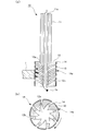
- FIG. 1 is a schematic configuration diagram of a grindstone tool 10 according to the present embodiment.
- 2 is a cross-sectional view of the grindstone tool 10 of FIG. 1
- FIG. 2 (a) is a cross-sectional view along the axial direction
- FIG. 2 (b) is a cross-sectional view along the radial direction of the head portion. is there.
- the grindstone tool 10 has a tubular shaft portion 11 having a communication hole 11a inside, as shown in FIGS. 1 and 2A.
- a cylindrical head portion 12 through which a hollow portion 12a connected to the communication hole 11a of the shaft portion 11 passes is coaxially and integrally connected to the inside and the lower side. The diameter is larger than that of the portion 11.
- the head portion 12 is formed with a plurality of communication holes 12b that communicate between the hollow portion 12a and the outer peripheral surface at predetermined intervals in the circumferential direction and the axial direction of the head portion 12.
- the communication hole 12b is in the radial direction of the head portion 12 (the one-dot chain line in FIG. 2 (b) is one direction in the boundary portion (most axial side) with the hollow portion 12a. 2), but toward the outer peripheral surface side, from the radial direction of the head portion 12, the rotational direction (the rotational direction indicated by the arrow in FIG. 2B (rotating direction of the grindstone tool 10)) forward side Draws an arc that slopes in a circle.
- the communication hole 12 b has an inclination angle from the radial direction of the head portion 12 to the front side in the rotation direction, and the inclination angle increases smoothly toward the outer peripheral surface side of the head portion 12.
- the communication hole 12b is positioned closer to the distal end side (lower side in FIG. 2A) toward the axial center side of the head portion 12. That is, the communication hole 12b has a spiral shape.
- the communication hole 12b has a tapered shape in which the diameter size increases toward the axial center side of the head portion 12.
- reference numeral 14a denotes a chip pocket (pore) between the abrasive grains 14.
- FIG. 3 is an operation explanatory view of the grindstone tool 10 according to the present embodiment.
- 4 is a cross-sectional view of the grindstone tool 10 of FIG. 3
- FIG. 4 (a) is a cross-sectional view along the axial direction
- FIG. 4 (b) is a cross-section along the radial direction of the head portion.
- the abrasive grains 14 are fixed to the metal base (iron, maraging steel, etc.) made of the shaft portion 11 and the head portion 12 as described above, in particular, to the entire outer peripheral surface of the head portion 12 via the bonding material 13.
- the head portion 12 is rotated at a high speed via the shaft portion 11, and fluid is introduced into the communication hole 11 a of the shaft portion 11.
- the abrasive grains 14 grind the workpiece 1.
- the grinding fluid 2 supplied into the communication hole 11a of the shaft portion 11 is supplied to the hollow portion 12a of the head portion 12 and circulates through the hollow portion 12a (see FIG. 4). From the lower side) to the outside.
- the hollow portion 12a of the head portion 12 is sucked into the communication hole 12b by the flow of the grinding fluid 2.
- the communication hole 12b of the head portion 12 sucks the chips 1a generated from the workpiece 1 into the hollow portion 12a by sucking the chips 1a from the chip pocket 14a.
- the chips 1 a fed into the hollow portion 12 a are discharged to the outside from the front end side of the head portion 12 together with the grinding liquid 2.
- the chips 1a in the chip pocket 14a are sucked into the communication hole 12b and entered into the hollow portion 12a. It is sent out and discharged from the front end side of the head portion 12a to the outside.
- the chip pocket 14a is not clogged with the chips 1a, so that the hollow portion is surely formed. It can be sent to 12a and discharged from the front end side of the head portion 12a to the outside.
- the communication hole 12b in the present embodiment has an inclination angle forward from the radial direction of the head portion 12 in the rotational direction, and the inclination angle increases smoothly toward the outer peripheral surface side of the head portion 12, Using the rotational force of the grindstone tool 10, the chips 1a are surely delivered to the hollow portion 12a without being clogged with the chips 1a sucked into the communication hole 12b, and discharged from the front end side of the head portion 12a to the outside. be able to.
- the communication hole 12b in the present embodiment is positioned closer to the tip end side of the head portion 12 toward the axial center side of the head portion 12, the grinding fluid 2 and the chips 1a that circulate in the hollow portion 12a toward the tip end side.
- the flow into the communication hole 12b can be greatly suppressed.
- tip 1a can be more reliably contained without clogging the chip
- the taper rate and the inclination angle of the taper shape are values that make it easier to send chips 1a to the hollow portion 12a hydrodynamically in consideration of the rotational direction and weight of the grinding wheel tool 10 during grinding of the workpiece 1. It is good to do.
- the boundary portion between the communication hole 12b and the hollow portion 12a is oriented in the radial direction of the head portion 12.
- the present invention is not limited to this, and the communication hole 12b is not limited to the head portion. It is good also as what has an inclination angle to the rotation direction front side from 12 radial directions.
- the base metal part of the grindstone tool 10 according to the present embodiment can be easily formed using a three-dimensional laminating method.
- the three-dimensional laminating method since the design is performed by 3D-CAD, the molding can be easily performed even if the number of the communication holes 12b is large.
- the grindstone tool 10 according to the present embodiment can be manufactured by fixing the abrasive grains 14 through the binder 13 by electrodeposition.
- electrodeposition method it is preferable to prevent the abrasive grains 14 from being fixed inside the communication holes 12b, but they may be fixed. The above is description of the grindstone tool which concerns on Example 1 of this invention.
- Example 2 The grindstone tool according to Example 2 of the present invention is obtained by changing the shapes of the communication hole, the hollow portion, and the communication hole of the grindstone tool according to Example 1 of the present invention.
- description of the part which is common in the grindstone tool which concerns on Example 1 of this invention is abbreviate
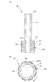
- FIG. 5 is a cross-sectional view of the grindstone tool 20 according to the present embodiment
- FIG. 5A is a cross-sectional view along the axial direction
- FIG. 5B is a cross-section along the radial direction of the head portion.
- FIG. 6A and 6B are cross-sectional views for explaining the operation of the grindstone tool according to the present embodiment.
- FIG. 6A is a cross-sectional view along the axial direction
- FIG. 6B is a radial view of the head portion.
- the communication hole 22b in this embodiment is located closer to the tip side of the head portion 12 (lower side of FIG. 5A) toward the axial center side of the head portion 22.
- the communication hole 22b has an inclination angle forward from the radial direction of the head portion 22 in the rotational direction (the rotational direction indicated by the arrow in FIG. 5B (of the grindstone tool 20)). It has a straight line shape.
- the communication hole 22b in the present embodiment is different from the communication hole 12b in the first embodiment, and the inclination angle does not change between the outer peripheral surface side and the axial center side of the head section 22, and therefore the inside of the head section 22 in the present embodiment.
- the diameter size of the communication hole 21a inside the hollow portion 22a and the shaft portion 21 is naturally larger than the size of the diameter of the hollow portion 11a and the communication hole 11a in the first embodiment.
- Abrasive grains 24 are fixed to the entire outer periphery of the head portion 22 of a metal base (iron, maraging steel, etc.) consisting of the shaft portion 21 and the head portion 22 as described above, with a binder 23 interposed therebetween.
- the head portion 22 is rotated at a high speed via the shaft portion 21, and a grinding fluid that is a fluid is formed in the communication hole 21 a of the shaft portion 21.
- the abrasive grains 24 grind the workpiece 1 and the shaft portion.
- the grinding fluid 2 supplied into the communication hole 21a of the 21 is supplied to the hollow portion 22a of the head portion 22 and circulates through the hollow portion 22a to the tip side of the head portion 22 (the lower side in FIG. 6). Is discharged to the outside.
- the hollow portion 22a of the head portion 22 is sucked into the communication hole 22b by the circulation of the grinding liquid 2.
- the communication hole 22b of the head portion 22 sucks the chips 1a generated from the workpiece 1 into the hollow portion 22a by sucking the chips 1a from the chip pocket 24a.
- the chips 1 a fed into the hollow portion 22 a are discharged together with the grinding liquid 2 from the front end side of the head portion 22 to the outside.
- the chips 1a in the chip pocket 24a are sucked into the communication hole 22b and entered into the hollow portion 22a. This is sent out and discharged from the front end side of the head portion 22a to the outside.
- the chip pocket 24a is not clogged with the chips 1a, so that the hollow portion is surely formed. It can send out to 22a and can discharge
- the occurrence of clogging can be greatly suppressed even when the amount of chips 1a generated per unit time is large as in high-feed machining or the like. .
- the communication hole 22b in this embodiment has a linear shape having an inclination angle forward from the radial direction of the head portion 22 in the rotational direction, the chips 1a are surely hollowed by using the rotational force of the grindstone tool 20. It can send out to the part 12a and can discharge
- the communication hole 22b in the present embodiment is positioned closer to the tip end side of the head portion 22 toward the axial center side of the head portion 22, the grinding fluid 2 and the chips 1a that circulate in the hollow portion 22a toward the tip end side.
- the flow into the communication hole 22b can be greatly suppressed.
- the linear inclination angle is preferably set to a value that allows the chips 1a to be more easily delivered to the hollow portion 22a in consideration of the rotational direction and weight of the grindstone tool 20 during grinding of the workpiece 1.
- the communication hole 22b may have a tapered shape in which the diameter size increases toward the outer peripheral surface side of the head portion 22, similarly to the communication hole 12b of the first embodiment. By doing in this way, it can suppress that the chip 1a stored in the communicating hole 22b enters into the inside of the hollow part 22a, and the chip 1a stored in the communicating hole 22b Without clogging the hole 22b, it can be reliably discharged to the outside.
- the base metal part of the grindstone tool 20 according to the present embodiment can be created by machining. And after shaping
- the grinding fluid 2 is used.
- the present invention is not limited to this.
- other liquids such as water, or gases such as air can be used. It is.
- the grinding fluid 2 is separately supplied to the communication holes 12b and 22b.
- the chips 1a preceded by the surface-side chips 1a are pushed out to the hollow portion 12a, the communication holes Even if nothing is supplied to 12b and 22b, the same effects as those of the first and second embodiments can be obtained.
- the grindstone tool according to the present invention has been described.
- the grindstone tool according to the present invention is fixed to the cylindrical head portion through which the hollow portion passes and the entire outer peripheral surface of the head portion.
- the hollow portion of the head portion is supplied with fluid, and the head portion communicates between the hollow portion and the outer peripheral surface in a rotational direction from the radial direction of the head portion.
- a plurality of communication holes having an inclination angle toward the front side are formed.
- the grindstone tool according to the present invention can greatly suppress the occurrence of clogging even when the amount of chips generated per unit time is large as in high-feed machining, etc. Can be used very beneficially.
Abstract
Description
内部を中空部が貫通する円筒状をなすヘッド部と、
前記ヘッド部の外周面の全体にわたって固着された砥粒とを備え、
前記ヘッド部の前記中空部は、流体を供給され、
前記ヘッド部には、前記中空部と前記外周面との間を連通し当該ヘッド部の径方向より回転方向前方側へ傾斜角度を有する連通孔が、複数形成されている
ことを特徴とする。 The grindstone tool according to the first invention for solving the above-mentioned problems is
A cylindrical head part through which the hollow part penetrates,
Abrasive grains fixed over the entire outer peripheral surface of the head portion,
The hollow part of the head part is supplied with fluid,
The head portion is formed with a plurality of communication holes that communicate between the hollow portion and the outer peripheral surface and have an inclination angle forward from the radial direction of the head portion in the rotational direction.
上記第1の発明に係る砥石工具において、
前記連通孔は、前記外周面側へ向かうほど前記傾斜角度が滑らかに増大する
ことを特徴とする。 The grindstone tool according to the second invention for solving the above-mentioned problems is
In the grindstone tool according to the first invention,
The communication hole is characterized in that the inclination angle increases smoothly toward the outer peripheral surface side.
上記第1の発明に係る砥石工具において、
前記連通孔は直線形状をなしている
ことを特徴とする。 A grindstone tool according to a third invention for solving the above-mentioned problems is as follows.
In the grindstone tool according to the first invention,
The communication hole has a linear shape.
上記第2の発明に係る砥石工具において、
前記連通孔は、前記ヘッド部の軸心側へ向かうほど前記ヘッド部の先端側に位置するように傾斜する
ことを特徴とする。 A grindstone tool according to a fourth invention for solving the above-mentioned problems is as follows.
In the grindstone tool according to the second invention,
The communication hole is inclined so as to be positioned closer to the distal end side of the head portion toward the axial center side of the head portion.
上記第3の発明に係る砥石工具において、
前記連通孔は、前記ヘッド部の軸心側へ向かうほど前記ヘッド部の先端側に位置するように傾斜する
ことを特徴とする。 A grindstone tool according to a fifth invention for solving the above-mentioned problems is as follows.
In the grindstone tool according to the third invention,
The communication hole is inclined so as to be positioned closer to the distal end side of the head portion toward the axial center side of the head portion.
上記第4の発明に係る砥石工具において、
前記連通孔は、前記ヘッド部の軸心側へ向かうほど径サイズが大きくなる
ことを特徴とする。 A grindstone tool according to a sixth invention for solving the above-mentioned problems is as follows.
In the grindstone tool according to the fourth invention,
The communication hole is characterized in that the diameter size increases toward the axial center side of the head portion.
上記第5の発明に係る砥石工具において、
前記連通孔は、前記ヘッド部の軸心側へ向かうほど径サイズが大きくなる
ことを特徴とする。 A grindstone tool according to a seventh invention for solving the above-mentioned problems is as follows.
In the grindstone tool according to the fifth invention,
The communication hole is characterized in that the diameter size increases toward the axial center side of the head portion.
本発明の実施例1に係る砥石工具について、まず、図1,2を用いて説明する。図1は、本実施例に係る砥石工具10の概略構成図である。図2は、図1の砥石工具10の断面図であり、図2(a)は、軸心方向に沿った断面図、図2(b)は、ヘッド部の径方向に沿った断面図である。 [Example 1]
First, a grindstone tool according to Example 1 of the present invention will be described with reference to FIGS. FIG. 1 is a schematic configuration diagram of a
以上が、本発明の実施例1に係る砥石工具の説明である。 Moreover, the base metal part of the
The above is description of the grindstone tool which concerns on Example 1 of this invention.
本発明の実施例2に係る砥石工具は、本発明の実施例1に係る砥石工具の、連絡孔、中空部及び連通孔の形状を変更したものである。以下では、本発明の実施例1に係る砥石工具と共通する部分の説明は一部省略する。 [Example 2]
The grindstone tool according to Example 2 of the present invention is obtained by changing the shapes of the communication hole, the hollow portion, and the communication hole of the grindstone tool according to Example 1 of the present invention. Below, description of the part which is common in the grindstone tool which concerns on Example 1 of this invention is abbreviate | omitted partially.
以上が、本発明の実施例2に係る砥石工具の説明である。 Moreover, the base metal part of the
The above is description of the grindstone tool which concerns on Example 2 of this invention.
1a 切屑
2 研削液
10,20 砥石工具
11,21 軸部
11a,21a 連絡孔
12,22 ヘッド部
12a,22a 中空部
12b,22b 連通孔
13,23 結合材
14,24 砥粒
14a,24a チップポケット(気孔) DESCRIPTION OF
Claims (7)
- 内部を中空部が貫通する円筒状をなすヘッド部と、
前記ヘッド部の外周面の全体にわたって固着された砥粒とを備え、
前記ヘッド部の前記中空部は、流体を供給され、
前記ヘッド部には、前記中空部と前記外周面との間を連通し当該ヘッド部の径方向より回転方向前方側へ傾斜角度を有する連通孔が、複数形成されている
ことを特徴とする砥石工具。 A cylindrical head part through which the hollow part penetrates,
Abrasive grains fixed over the entire outer peripheral surface of the head portion,
The hollow part of the head part is supplied with fluid,
The grindstone characterized in that the head portion is formed with a plurality of communicating holes that communicate between the hollow portion and the outer peripheral surface and have an inclination angle forward from the radial direction of the head portion in the rotational direction. tool. - 前記連通孔は、前記外周面側へ向かうほど前記傾斜角度が滑らかに増大する
ことを特徴とする請求項1に記載の砥石工具。 The grindstone tool according to claim 1, wherein the communication hole has the inclination angle that increases smoothly toward the outer peripheral surface. - 前記連通孔は直線形状をなしている
ことを特徴とする請求項1に記載の砥石工具。 The grindstone tool according to claim 1, wherein the communication hole has a linear shape. - 前記連通孔は、前記ヘッド部の軸心側へ向かうほど前記ヘッド部の先端側に位置するように傾斜する
ことを特徴とする請求項2に記載の砥石工具。 3. The grindstone tool according to claim 2, wherein the communication hole is inclined so as to be positioned closer to a distal end side of the head portion toward the axial center side of the head portion. - 前記連通孔は、前記ヘッド部の軸心側へ向かうほど前記ヘッド部の先端側に位置するように傾斜する
ことを特徴とする請求項3に記載の砥石工具。 4. The grindstone tool according to claim 3, wherein the communication hole is inclined so as to be positioned closer to a tip end side of the head portion toward the axial center side of the head portion. - 前記連通孔は、前記ヘッド部の軸心側へ向かうほど径サイズが大きくなるテーパ形状をなしている
ことを特徴とする請求項4に記載の砥石工具。 The grindstone tool according to claim 4, wherein the communication hole has a tapered shape in which a diameter size increases toward the axial center side of the head portion. - 前記連通孔は、前記ヘッド部の軸心側へ向かうほど径サイズが大きくなるテーパ形状をなしている
ことを特徴とする請求項5に記載の砥石工具。 The grindstone tool according to claim 5, wherein the communication hole has a tapered shape whose diameter size increases toward the axial center side of the head portion.
Priority Applications (4)
| Application Number | Priority Date | Filing Date | Title |
|---|---|---|---|
| US15/038,294 US10213904B2 (en) | 2013-12-25 | 2014-09-09 | Grinding wheel tool |
| BR112016011044A BR112016011044A2 (en) | 2013-12-25 | 2014-09-09 | emery |
| CA2931343A CA2931343C (en) | 2013-12-25 | 2014-09-09 | Grinding wheel tool |
| DE112014006022.4T DE112014006022T5 (en) | 2013-12-25 | 2014-09-09 | Grinding wheel tool |
Applications Claiming Priority (2)
| Application Number | Priority Date | Filing Date | Title |
|---|---|---|---|
| JP2013-266324 | 2013-12-25 | ||
| JP2013266324A JP6209081B2 (en) | 2013-12-25 | 2013-12-25 | Whetstone tool |
Publications (1)
| Publication Number | Publication Date |
|---|---|
| WO2015098194A1 true WO2015098194A1 (en) | 2015-07-02 |
Family
ID=53478077
Family Applications (1)
| Application Number | Title | Priority Date | Filing Date |
|---|---|---|---|
| PCT/JP2014/073728 WO2015098194A1 (en) | 2013-12-25 | 2014-09-09 | Grinding wheel tool |
Country Status (6)
| Country | Link |
|---|---|
| US (1) | US10213904B2 (en) |
| JP (1) | JP6209081B2 (en) |
| BR (1) | BR112016011044A2 (en) |
| CA (1) | CA2931343C (en) |
| DE (1) | DE112014006022T5 (en) |
| WO (1) | WO2015098194A1 (en) |
Cited By (1)
| Publication number | Priority date | Publication date | Assignee | Title |
|---|---|---|---|---|
| US10543583B2 (en) | 2014-12-12 | 2020-01-28 | Mitsubishi Heavy Industries Machine Tool Co., Ltd. | Grinding tool and manufacturing method therefor |
Families Citing this family (4)
| Publication number | Priority date | Publication date | Assignee | Title |
|---|---|---|---|---|
| DE102016226273A1 (en) * | 2016-12-28 | 2018-06-28 | Robert Bosch Gmbh | Abrasives fixture |
| KR102316563B1 (en) * | 2017-05-22 | 2021-10-25 | 엘지디스플레이 주식회사 | Organic Light-Emitting Display device having an upper substrate formed by a metal and Method of fabricating the same |
| CN107538359B (en) * | 2017-09-08 | 2023-10-31 | 清华大学 | Powder mixing grinding wheel and preparation method thereof |
| CN109108760A (en) * | 2018-11-15 | 2019-01-01 | 刘景岳 | A kind of dustless type construction wall grinding device of hand-held |
Citations (4)
| Publication number | Priority date | Publication date | Assignee | Title |
|---|---|---|---|---|
| JPH02126761U (en) * | 1989-03-29 | 1990-10-18 | ||
| JPH05269669A (en) * | 1992-03-24 | 1993-10-19 | Nisshin Koki Kk | Grinding tool |
| JP3166021U (en) * | 2010-11-17 | 2011-02-17 | 伊藤 幸男 | Small diameter grinding wheel tool |
| EP2324945A1 (en) * | 2009-11-24 | 2011-05-25 | ALEIT GmbH | Rotating tool for removing material with seal-free, forced and centrifugal coolant lubricant supply |
Family Cites Families (14)
| Publication number | Priority date | Publication date | Assignee | Title |
|---|---|---|---|---|
| US2819568A (en) * | 1957-04-18 | 1958-01-14 | John N Kasick | Grinding wheel |
| US3282263A (en) * | 1963-07-29 | 1966-11-01 | Christensen Diamond Prod Co | Face discharge cutting blades |
| US3754359A (en) * | 1970-09-16 | 1973-08-28 | Spam D Avray | Abrasion tools |
| US4058936A (en) * | 1976-01-20 | 1977-11-22 | Miksa Marton | Vacuum sander |
| JPS5859765A (en) * | 1981-10-07 | 1983-04-08 | Hitachi Ltd | Grinder |
| JPS58143162U (en) * | 1982-03-19 | 1983-09-27 | 株式会社東芝 | drilling tool |
| JPH07237131A (en) * | 1994-03-01 | 1995-09-12 | Hiroaki Yasuda | Pad for grinding material furnishing |
| US5993297A (en) * | 1994-09-06 | 1999-11-30 | Makino Inc. | Superabrasive grinding wheel with integral coolant passage |
| FR2752762B1 (en) * | 1996-08-29 | 1998-10-02 | Snecma | GRINDING WHEEL WITH BUILT-IN WATERING |
| FR2892653B1 (en) * | 2005-10-27 | 2009-04-10 | Airbus France Sas | TOOL FOR MACHINING PARTS IN COMPOSITE MATERIALS |
| JP2007144597A (en) | 2005-11-30 | 2007-06-14 | Tdk Corp | Electrodeposition grindstone and grinding method using it |
| US8641479B2 (en) * | 2010-09-01 | 2014-02-04 | Ford Motor Company | Tool assembly for machining a bore |
| JP5936489B2 (en) * | 2012-08-29 | 2016-06-22 | 三菱重工工作機械株式会社 | Whetstone tool |
| US9555485B2 (en) * | 2014-04-25 | 2017-01-31 | Gws Tool, Llc | Diamond plated grinding endmill for advanced hardened ceramics machining |
-
2013
- 2013-12-25 JP JP2013266324A patent/JP6209081B2/en active Active
-
2014
- 2014-09-09 BR BR112016011044A patent/BR112016011044A2/en not_active Application Discontinuation
- 2014-09-09 DE DE112014006022.4T patent/DE112014006022T5/en not_active Withdrawn
- 2014-09-09 WO PCT/JP2014/073728 patent/WO2015098194A1/en active Application Filing
- 2014-09-09 CA CA2931343A patent/CA2931343C/en not_active Expired - Fee Related
- 2014-09-09 US US15/038,294 patent/US10213904B2/en not_active Expired - Fee Related
Patent Citations (4)
| Publication number | Priority date | Publication date | Assignee | Title |
|---|---|---|---|---|
| JPH02126761U (en) * | 1989-03-29 | 1990-10-18 | ||
| JPH05269669A (en) * | 1992-03-24 | 1993-10-19 | Nisshin Koki Kk | Grinding tool |
| EP2324945A1 (en) * | 2009-11-24 | 2011-05-25 | ALEIT GmbH | Rotating tool for removing material with seal-free, forced and centrifugal coolant lubricant supply |
| JP3166021U (en) * | 2010-11-17 | 2011-02-17 | 伊藤 幸男 | Small diameter grinding wheel tool |
Cited By (1)
| Publication number | Priority date | Publication date | Assignee | Title |
|---|---|---|---|---|
| US10543583B2 (en) | 2014-12-12 | 2020-01-28 | Mitsubishi Heavy Industries Machine Tool Co., Ltd. | Grinding tool and manufacturing method therefor |
Also Published As
| Publication number | Publication date |
|---|---|
| JP6209081B2 (en) | 2017-10-04 |
| JP2015120228A (en) | 2015-07-02 |
| CA2931343A1 (en) | 2015-07-02 |
| US10213904B2 (en) | 2019-02-26 |
| BR112016011044A2 (en) | 2017-09-12 |
| CA2931343C (en) | 2018-05-01 |
| US20160288294A1 (en) | 2016-10-06 |
| DE112014006022T5 (en) | 2016-10-06 |
Similar Documents
| Publication | Publication Date | Title |
|---|---|---|
| JP5936489B2 (en) | Whetstone tool | |
| WO2015098194A1 (en) | Grinding wheel tool | |
| EP3134224B1 (en) | Diamond plated grinding endmill for advanced hardened ceramics machining | |
| JP6098440B2 (en) | Ball end mill | |
| WO2013114527A1 (en) | Honing tool | |
| WO2015098195A1 (en) | Grinding wheel tool | |
| JP6084455B2 (en) | Rotary cutting tool | |
| JP6280240B2 (en) | Grinding wheel tool and manufacturing method thereof | |
| JP2005319544A (en) | Hole machining tool, and method of grinding outer periphery of the tool | |
| JP4693592B2 (en) | Drilling tool | |
| JP2010260115A (en) | Tool for drilling hole in fiber-reinforced composite material | |
| JP2008229764A (en) | Rotary tool and machining method | |
| JP2003080411A (en) | Small diametrical drill for deep hole drilling | |
| JP2006136957A (en) | Grinding wheel | |
| JP6436647B2 (en) | Electrodeposition reamer | |
| JP2020011325A (en) | Electrocasting grindstone | |
| JP2018167346A (en) | Cutting tool | |
| RU51927U1 (en) | DEVICE FOR SUBMITTING LUBRICANT COOLANT LIQUID (LUBRICANTS) AT FLAT SURFACE GRINDING | |
| JP2007190645A (en) | Fixture for preventing fall of workpiece | |
| JP2018103289A (en) | Reamer | |
| JP2005297171A (en) | Liquid self-feeding type spindle | |
| JP2018051697A (en) | Grinding tool |
Legal Events
| Date | Code | Title | Description |
|---|---|---|---|
| 121 | Ep: the epo has been informed by wipo that ep was designated in this application |
Ref document number: 14875223 Country of ref document: EP Kind code of ref document: A1 |
|
| ENP | Entry into the national phase |
Ref document number: 2931343 Country of ref document: CA |
|
| WWE | Wipo information: entry into national phase |
Ref document number: 15038294 Country of ref document: US |
|
| REG | Reference to national code |
Ref country code: BR Ref legal event code: B01A Ref document number: 112016011044 Country of ref document: BR |
|
| WWE | Wipo information: entry into national phase |
Ref document number: 112014006022 Country of ref document: DE |
|
| 122 | Ep: pct application non-entry in european phase |
Ref document number: 14875223 Country of ref document: EP Kind code of ref document: A1 |
|
| ENP | Entry into the national phase |
Ref document number: 112016011044 Country of ref document: BR Kind code of ref document: A2 Effective date: 20160516 |