WO2015098009A1 - 測定システム及び測定方法 - Google Patents
測定システム及び測定方法 Download PDFInfo
- Publication number
- WO2015098009A1 WO2015098009A1 PCT/JP2014/006121 JP2014006121W WO2015098009A1 WO 2015098009 A1 WO2015098009 A1 WO 2015098009A1 JP 2014006121 W JP2014006121 W JP 2014006121W WO 2015098009 A1 WO2015098009 A1 WO 2015098009A1
- Authority
- WO
- WIPO (PCT)
- Prior art keywords
- ear
- artificial
- measurement system
- vibration
- unit
- Prior art date
- Legal status (The legal status is an assumption and is not a legal conclusion. Google has not performed a legal analysis and makes no representation as to the accuracy of the status listed.)
- Ceased
Links
Images

Classifications
-
- G—PHYSICS
- G01—MEASURING; TESTING
- G01H—MEASUREMENT OF MECHANICAL VIBRATIONS OR ULTRASONIC, SONIC OR INFRASONIC WAVES
- G01H17/00—Measuring mechanical vibrations or ultrasonic, sonic or infrasonic waves, not provided for in the other groups of this subclass
-
- H—ELECTRICITY
- H04—ELECTRIC COMMUNICATION TECHNIQUE
- H04M—TELEPHONIC COMMUNICATION
- H04M1/00—Substation equipment, e.g. for use by subscribers
- H04M1/24—Arrangements for testing
-
- H—ELECTRICITY
- H04—ELECTRIC COMMUNICATION TECHNIQUE
- H04R—LOUDSPEAKERS, MICROPHONES, GRAMOPHONE PICK-UPS OR LIKE ACOUSTIC ELECTROMECHANICAL TRANSDUCERS; ELECTRIC HEARING AIDS; PUBLIC ADDRESS SYSTEMS
- H04R29/00—Monitoring arrangements; Testing arrangements
- H04R29/001—Monitoring arrangements; Testing arrangements for loudspeakers
-
- H—ELECTRICITY
- H04—ELECTRIC COMMUNICATION TECHNIQUE
- H04R—LOUDSPEAKERS, MICROPHONES, GRAMOPHONE PICK-UPS OR LIKE ACOUSTIC ELECTROMECHANICAL TRANSDUCERS; ELECTRIC HEARING AIDS; PUBLIC ADDRESS SYSTEMS
- H04R5/00—Stereophonic arrangements
- H04R5/027—Spatial or constructional arrangements of microphones, e.g. in dummy heads
-
- H—ELECTRICITY
- H04—ELECTRIC COMMUNICATION TECHNIQUE
- H04R—LOUDSPEAKERS, MICROPHONES, GRAMOPHONE PICK-UPS OR LIKE ACOUSTIC ELECTROMECHANICAL TRANSDUCERS; ELECTRIC HEARING AIDS; PUBLIC ADDRESS SYSTEMS
- H04R2460/00—Details of hearing devices, i.e. of ear- or headphones covered by H04R1/10 or H04R5/033 but not provided for in any of their subgroups, or of hearing aids covered by H04R25/00 but not provided for in any of its subgroups
- H04R2460/13—Hearing devices using bone conduction transducers
-
- H—ELECTRICITY
- H04—ELECTRIC COMMUNICATION TECHNIQUE
- H04R—LOUDSPEAKERS, MICROPHONES, GRAMOPHONE PICK-UPS OR LIKE ACOUSTIC ELECTROMECHANICAL TRANSDUCERS; ELECTRIC HEARING AIDS; PUBLIC ADDRESS SYSTEMS
- H04R2499/00—Aspects covered by H04R or H04S not otherwise provided for in their subgroups
- H04R2499/10—General applications
- H04R2499/11—Transducers incorporated or for use in hand-held devices, e.g. mobile phones, PDA's, camera's
Definitions
- the present invention relates to a measurement system and a measurement method for evaluating an electronic device that transmits sound based on vibration of a vibrating body to a user.
- Patent Document 1 describes an electronic device such as a mobile phone that transmits air conduction sound and bone conduction sound to a user (user).
- air conduction sound is sound transmitted to the auditory nerve of a user by vibration of air that is caused by vibration of an object being transmitted to the eardrum through the external auditory canal.
- Patent Document 1 describes that bone conduction sound is sound transmitted to the user's auditory nerve through a part of the user's body (for example, cartilage of the outer ear) that contacts the vibrating object. ing.
- Patent Document 1 In the telephone set described in Patent Document 1, it is described that a short plate-like vibrating body made of a piezoelectric bimorph and a flexible material is attached to the outer surface of a housing via an elastic member. Further, in Patent Document 1, when a voltage is applied to the piezoelectric bimorph of the vibrating body, the vibrating body vibrates due to the expansion and contraction of the piezoelectric material in the longitudinal direction, and the user contacts the vibrating body with the auricle. It is described that air conduction sound and bone conduction sound are transmitted to the user.
- the inventor differs from the telephone described in the above-mentioned Patent Document 1 in that air conduction sound generated by vibrating a panel such as a display panel or a protective panel arranged on the surface of the mobile phone, and a panel that vibrates.
- a panel such as a display panel or a protective panel arranged on the surface of the mobile phone
- a panel that vibrates.
- vibration sound which is a sound component generated by vibration transmission transmitted to the human ear.
- the inventor can generate sound on the human body by vibration of the vibrating body. It has been found that it is preferable to measure how close to the human body as much as possible how much the sensory sound pressure, which is a combination of pressure and vibration amount, is transmitted.
- the first measurement method is to measure a vibration amount as a voltage by pressing a vibrating body to be measured against an artificial mastoid for measuring a bone-conducting vibrator that mechanically simulates a milk projecting part behind an ear.
- a vibration pickup such as a piezoelectric acceleration pickup is pressed against a vibration body to be measured, and the amount of vibration is measured as a voltage.
- the measurement voltage obtained by the first measurement method is a voltage in which the characteristics of the human body when the vibrating body is pressed against the milk projecting part behind the human ear are mechanically weighted.
- the characteristic of vibration transmission when is pressed against the human ear is not a weighted voltage.
- the measurement voltage obtained by the second measurement method is obtained by directly measuring the vibration amount of the vibrating body from the vibrating object. Similarly, the characteristics of vibration transmission to the human ear are weighted. Not the voltage. Therefore, even if the vibration amount of the vibrating body is measured by the conventional measurement method, the vibration amount transmitted from the electronic device to the human body cannot be correctly evaluated.
- the present invention has been made in view of the above-described viewpoints, and provides a measurement system and a measurement method capable of measuring a body sensation sound pressure in which a vibration amount and a sound pressure transmitted to a human body due to vibration of a vibration body are combined and approximated to a human body. It is intended to provide.
- a measurement system is a measurement system for evaluating an electronic device that presses a vibrating body against an ear of a human body and transmits a sound based on the vibration of the vibrating body to a user, and imitates the human ear
- a vibration detection unit that is disposed on a surface of the artificial mandible part opposite to the ear model, and detects and outputs vibration transmitted to the artificial mandible part.
- the present invention it is possible to provide a measurement system and a measurement method capable of measuring a body sensation sound pressure obtained by combining a vibration amount transmitted to a human body by the vibration of the vibration body and a sound pressure by approximating the human body.
- FIG. 2 is a partial detail view of the ear mold part of FIG. 1. It is a figure which shows the name of each part of the ear mold
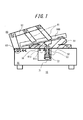
- FIG. 1 is a diagram showing a schematic configuration of a measurement system according to the first embodiment of the present invention.
- the measurement system 10 according to the present embodiment includes a base 30, an ear mold 50, measurement systems 60 and 70, and the like.
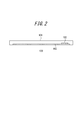
- the electronic device 100 is, for example, a smartphone having a rectangular panel 103 larger than a human ear on the surface of a rectangular casing 101. It is a mobile phone, and the panel 103 vibrates as a vibrating body.
- the base 30 may include a metal base such as SUS, and the leg portion may include a vibration isolation member made of a rubber material. As a result, vibrations from the placed desk are unlikely to adversely affect the measurement.
- the ear mold part 50 imitates an ear of a human body, and includes an ear model 51 corresponding to a human pinna and an artificial external ear canal part 52 coupled to the ear model 51.
- the artificial external auditory canal portion 52 has a size that covers the ear model 51, and an artificial external ear canal 53 is formed at the center.
- the ear mold part 50 is supported by the base 30 at the periphery of the artificial external ear canal part 52.
- the ear mold part 50 (the ear model 51 and the artificial external auditory canal part 52) is used for, for example, a human body model HATS (Head And Torso Simulator) or KEMAR (registered trademark: name of an electronic mannequin for acoustic research of Knowles Electronics). It is made of the same material as the average ear model (KB0060 to KB1091), for example, a material conforming to IEC60318-7. This material can be formed of a material such as rubber having a hardness of 35 to 55, for example. The rubber hardness may be measured in accordance with, for example, international rubber hardness (IRHD / M method) in accordance with JIS K-6253, ISO 48, or the like.
- HATS Head And Torso Simulator
- KEMAR registered trademark: name of an electronic mannequin for acoustic research of Knowles Electronics.
- This material can be formed of a material such as rubber having a hardness of 35
- the hardness measurement system As the hardness measurement system, a fully automatic type IRHD / M method micro size international rubber hardness meter GS680 manufactured by Teclock Co., Ltd. is preferably used.
- the ear mold portion 50 may be prepared by roughly preparing two to three types of different hardness, and replacing them.
- the length of the artificial external auditory canal 53 constituted by the artificial external auditory canal portion 52 corresponds to the length to the human eardrum, and is appropriately set within a range of 26 mm to 40 mm, for example. In the present embodiment, the length of the artificial external ear canal 53 is approximately 30 mm.
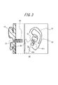
- the ear mold part 50 is a part facing the ear model 51, and the artificial mandible part 56 is arranged at a position adjacent to the artificial external ear canal part 52 but not overlapping.
- the artificial mandible 56 is roughly plate-shaped and may include a masseter rough surface, a muscular process, and a mandibular head to simulate a human body, as shown in FIG. A rectangular plate simplified from the viewpoint of cost may be used. However, here, only the upper half of the mandible of a person is simulated, and the lower half (such as chin and teeth) is omitted.
- the vibrating panel 103 as shown in FIG. 2 has a size that covers the ear, a part of the panel is in contact with the auricle, while the other part of the panel is in contact with the mandible through the skin. It is assumed that a vibration component (bone conduction component) is generated from the panel 103 via the mandible.
- a vibration component bone conduction component
- earphones or the like that are inserted into a person's external auditory canal and transmit sound by vibration, bone conduction components that are transmitted from the inside of the external auditory canal to the mandibular head may occur. Since the mandibular head of 56 is close to the artificial external auditory canal 52, the bone conduction component can be simulated.
- the artificial mandible 56 may be made of a metal material such as SUS or aluminum, or a hard resin material such as polycarbonate resin or acrylic resin.
- biomaterials such as a hydroxyapatite. With such a material, it is assumed that the vibration characteristic is close to that of a human bone, and the degree of calibration of the measured value can be reduced.
- the thickness of the artificial mandible 56 varies depending on the material.
- the metal material may have a thickness of about 0.1 mm to 2 mm
- the hard resin material may have a thickness of about 2 mm to 5 mm.
- the artificial mandible 56 has a vertical width of about 2.0 cm to 5 cm and a horizontal width of about 1.0 cm to 3 cm, for example.
- the vibration detection unit 60 is located on the surface opposite to the ear model 51 of the ear mold unit 50, at a position around the artificial external ear canal unit 52 and without the artificial mandible in plan view.
- a vibration detection element 61x is arranged.
- the vibration detection element 61x detects the amount of vibration transmitted mainly through the soft tissue such as the ear model 51 and the ear canal part 52 when the vibrating panel 103 is applied to the ear mold part 50. In other words, the vibration detection element 61x detects a vibration component that the vibration of the panel 103 directly shakes the inner ear and listens without going through the eardrum.
- the vibration detecting element 61y is disposed on the back side of the artificial mandible 56 described above, and measures the bone conduction component transmitted from the panel 103 via soft tissue such as human skin.
- the vibration detection elements 61x and 61y have a flat output characteristic in a frequency range (for example, 0.1 kHz to 30 kHz) that is a measurement target of the electronic device 100, for example, and are vibration detection that can accurately measure even light and fine vibrations. It is composed of elements.
- a vibration detection element for example, a vibration pickup such as a piezoelectric acceleration pickup, for example, a vibration pickup PV-08A manufactured by Rion Co., Ltd. can be used.
- the ear mold portion 50 is provided with a sound pressure measuring portion 70.
- the sound pressure measurement unit 70 measures the sound pressure of the sound propagated through the artificial external ear canal 53. That is, when the panel 103 is put on the human ear, the sound pressure measuring unit 70 oscillates by the vibration of the panel 103 and the sound pressure corresponding to the air conduction component heard directly through the eardrum, and the panel The sound pressure corresponding to the second air conduction component for listening to the sound generated by the ear itself through the eardrum due to the vibration of the ear canal due to the vibration of 103 is also measured.
- the sound pressure measuring unit 70 includes a microphone 71 held by a tube member 72 extending from the outer wall (the peripheral wall of the hole) of the artificial external ear canal 53.
- the microphone 71 includes a measurement capacitor microphone that has a flat output characteristic in the frequency range of the measurement target of the electronic device 100 and has a low self-noise level.
- a microphone 71 for example, a condenser microphone UC-53A manufactured by Rion Co., Ltd. can be used.
- the microphone 71 is disposed such that the sound pressure detection surface substantially coincides with the end surface of the artificial external ear canal unit 52. That is, it is arranged so as to be the same as the position of the human eardrum.
- the microphone 71 may be a probe microphone, for example, and may be supported by the base 30 and arranged in a floating state from the outer wall of the artificial external ear canal 53.
- the holding unit 80 will be described.
- the electronic device 100 is a mobile phone having a rectangular shape in a plan view such as a smartphone
- the both sides of the mobile phone are usually held by hands. Will be supported by.
- the pressing force and contact posture of the mobile phone against the ear vary depending on the person (user) or fluctuates during use.
- electronic device 100 is held by imitating such a usage mode of a mobile phone.
- the holding unit 80 includes support portions 81 that support both side portions of the electronic device 100.
- the support portion 81 is attached to the arm portion 82 so as to be capable of rotating around the shaft core.
- the other end portion of the arm portion 82 is attached to the movement adjusting portion 83 so as to be adjustable.
- the movement adjustment unit 83 is attached to the base 30 so as to be capable of parallel movement and rotation adjustment with respect to the base 30.
- the shaft core that rotatably holds each part can be repeatedly fastened and relaxed by a screw material or the like, thereby obtaining a predetermined holding force.
- the pressing force of the vibrating body (panel 103) on the ear mold portion 50 is adjusted.
- the pressing force is adjusted in the range of 0N to 10N, preferably in the range of 3N to 8N.
- the range of 0N to 10N is intended to enable measurement in a range sufficiently wider than the pressing force assumed when a human presses an electronic device against his / her ear to use a telephone call or the like. It is said.
- 0N for example, not only when the ear mold part 50 is in contact but not pressed, it can be held away from the ear mold part 50 by 1 cm so that measurement can be performed at each separation distance. It may be.
- the degree of attenuation due to the distance of the air conduction sound can also be measured by the microphone 71, and convenience as a measurement system is improved.
- the range of 3N to 8N usually assumes an average force range that a normal hearing person presses against an ear when making a call using a conventional speaker.
- vibration sound and air conduction sound are usually applied with a pressing force that is pressed by the user. Is preferably measurable.
- the vibrating body is not limited to a panel that covers a wide range of ears, but an electronic device having protrusions and corners that transmit vibration only to a part of the ear mold 50, for example, the part of the tragus. Even a device can be a measurement object of the present invention.
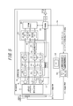
- FIG. 5 is a functional block diagram conceptually showing the configuration of the signal analysis unit 300 and related elements.
- two vibration amounts and sound pressure transmitted through the ear mold part 50 due to vibration of the electronic device 100 to be measured that is, a vibration component via the soft tissue, a bone conduction component via the mandible
- the sensory sound pressure is measured by combining any one of the derived components, a combination of the two components, or all of them.
- the signal analysis unit 300 includes an A / D conversion unit 410, a sensitivity adjustment unit 415, a frequency characteristic adjustment unit 420, a synthesis unit 425 that synthesizes the vibration component and the bone conduction component, and obtains a first synthesis component.
- the phase adjustment unit 430 capable of adjusting the phase of the vibration component (first combined component) with respect to the air conduction component, and the vibration component after the phase adjustment (first synthesis component) and the air conduction component.
- An output synthesis unit 440, a synthesis unit 450, a storage unit 460, and a control unit 470 that combine to obtain a human body sensory sound pressure (second synthesized component) are provided.
- the measurement system of the present invention may include a PC (personal computer) 500 (display unit 520 and CPU), a printer, and the like.
- the output of the analog signals from the vibration detection elements 61x and 61y and the microphone 71 are input to the respective A / D converters 410.
- the A / D conversion unit 410 includes an A / D conversion circuit (A / D) that converts an analog signal into a digital signal.
- the A / D conversion circuit of the A / D conversion unit 410 can handle, for example, 16 bits or more and 96 dB or more in terms of dynamic range.
- the A / D conversion circuit can be configured to change the dynamic range.
- the A / D converted signal is supplied to each sensitivity adjustment unit 415. Then, the amplitude of the A / D converted signal corresponding to each is adjusted manually or automatically to the required amplitude. Thereby, the error of the sensitivity of the vibration detection elements 61x and 61y and the sensitivity of the microphone 71 is corrected.
- the variable gain amplifier circuit (sensitivity correction amplifier) constituting the sensitivity adjustment unit 415 is configured to be able to adjust the amplitude of the A / D converted signal within a range of, for example, ⁇ 20 dB.
- the A / D conversion unit 410 and the sensitivity adjustment unit 415 may be arranged in reverse order.
- the output of the sensitivity adjustment unit 415 is supplied to the frequency characteristic adjustment unit 420.
- the frequency characteristic adjustment unit 420 adjusts the two equalizers (EQ) for adjusting the frequency characteristics of the detection signals by the vibration detection elements 61x and 61y and the frequency characteristics of the detection signal by the microphone 71 which is the output of the A / D conversion circuit.
- An equalizer (EQ) And the frequency characteristic of each input signal is adjusted independently to the frequency characteristic close
- the equalizer includes, for example, a multiband graphical equalizer, a low-pass filter, a high-pass filter, and the like.
- the outputs related to the vibration component and the bone conduction component are input to the output synthesis unit 425 and synthesized as one vibration component (first synthesis component).
- the phase adjustment unit 430 includes a variable delay circuit that adjusts the phase of the detection signal from the vibration detection element 61.
- phase adjustment can be made to actually bring the difference in the speed of sound transmitted through the artificial external auditory canal 52 and the artificial mandible 56 to the speed of sound propagating through the artificial external auditory canal.
- the phase of the detection signal (phase of the first composite component) by the vibration detection element 61 is set within a predetermined range by the variable delay circuit according to the measurement frequency range of the electronic device 100 to be measured. adjust.
- the detection by the vibration detection element 61 is performed by a variable delay circuit in a range of about ⁇ 10 ms (corresponding to ⁇ 100 Hz) and at least smaller than 0.1 ms (corresponding to 10 kHz).
- the phase of the signal (the phase of the first composite component) is adjusted.
- the phase adjustment by the variable delay circuit means that the phases of the detection signals of both the vibration detection element 61 and the microphone 71 are matched. Rather, it means that the phase of both is matched to the actual audibility of the ear.
- phase adjustment unit that adjusts the phase between the vibration detection element 61x that detects vibration transmission in the soft tissue and the vibration detection element 61y that detects vibration transmission in the artificial mandible 56 may be further provided. In this case, it is only necessary to adjust the phase of the vibration component before synthesizing the two vibration components.
- the output of the phase adjustment unit 430 is supplied to the output synthesis unit 440.
- the output combining unit 440 combines the detection signal (first combined component) from the vibration detecting element 61 whose phase is adjusted by the variable delay circuit and the detection signal from the microphone 71 that has passed through the frequency characteristic adjusting unit 420, 2 synthetic components are obtained.
- two vibration amounts and sound pressure transmitted by the vibration of the electronic device 100 to be measured that is, the sensory sound pressure obtained by combining the vibration transmission of the soft tissue, the bone conduction sound, and the air conduction sound are approximated to the human body. Can be obtained.
- the combined output of the output combining unit 440 is input to the analyzing unit 450.
- the analysis unit 450 includes three FFT units (fast Fourier transform) that analyze the frequency of the output from the output synthesis unit 440.
- the analysis unit 450 has three kinds of the second synthetic component obtained by synthesizing the first synthetic component with the air conduction component, only the air conduction component, the synthesis component (first synthesis component) of the two vibration routes. Then, fast Fourier transform processing is performed. Thereby, power spectrum data corresponding to each of the first synthesis component (vib), the air conduction component (air), and the second synthesis component (air + vib) is obtained from each FFT unit.
- Each FFT unit is set with an analysis point of a frequency component (power spectrum) according to the measurement frequency range of the electronic device 100. For example, when the measurement frequency range of the electronic device 100 is 100 Hz to 10 kHz, the frequency component at each point obtained by dividing the interval in the logarithmic graph of the measurement frequency range into 100 to 200 is analyzed.
- the output of each FFT unit is stored in the storage unit 460.
- the storage unit 460 may have a capacity equal to or larger than a triple buffer capable of holding analysis data (power spectrum data) by each FFT unit. And it can comprise so that the newest data can always be transmitted at the data transmission request timing from PC500 mentioned later.
- the control unit 470 is connected to the PC 500 via, for example, a connection cable 510 for an interface such as USB, RS-232C, SCSI, or a PC card, or a wireless connection line such as Wi-Fi (Wi-Fi) or BT (Blue).
- a connection cable 510 for an interface such as USB, RS-232C, SCSI, or a PC card, or a wireless connection line such as Wi-Fi (Wi-Fi) or BT (Blue).
- Wi-Fi Wi-Fi
- BT Bluetooth
- the signal analysis unit 300 can be configured as software executed on any suitable processor such as a CPU (Central Processing Unit), or can be configured by a DSP (Digital Signal Processor).
- the PC 500 has an evaluation application for the electronic device 100 by the measurement system 10.
- the evaluation application includes test signal data and is downloaded through, for example, a CD-ROM or a network.
- the test signal data includes a pure tone signal, a multisine signal, and a pure tone sweep signal.
- the PC500 displays the application screen based on an evaluation application on the display part 520, for example. Further, a command is transmitted to the signal analysis unit 300 based on information input via the application screen.
- the PC 500 receives a command response and data from the control unit 470, performs predetermined processing based on the received data, and displays the measurement result on the application screen. Further, if necessary, the measurement result may be output to a printer and printed.
- FIG. 6 is a diagram showing a schematic configuration of a main part of the measurement system according to the second embodiment of the present invention.
- the second embodiment further includes a human head model 130 to which the ear mold portion 50 in the first embodiment can be attached. Other points may be the same as in the first embodiment.
- the head model 130 is made of, for example, HATS or KEMAR (registered trademark).
- the artificial ear 131 of the head model 130 is detachable from the head model 130.
- the same effect as the measurement system 10 of the first embodiment can be obtained.
- the human head model 130 since the human head model 130 is provided, the evaluation according to the actual use mode in consideration of the influence of the head can be performed.
- the holding part holding an audio equipment and an electronic device since the holding part holding an audio equipment and an electronic device may be the same as Example 1, what is necessary is just to refer to FIG.
- the present invention is not limited to the above embodiment, and many variations or modifications are possible.
- the electronic device 100 to be measured has a wide panel 103 such as a smartphone and the panel 103 vibrates as a vibrating body.
- the electronic device in which the panel in contact with the ear vibrates can be evaluated in the same manner.
- not only a mobile phone but various earphones that call themselves other bone conduction methods can be evaluated in the same manner.
- the phase adjustment unit 430 is configured to delay the phase of the detection signal from the vibration detection element 61 with respect to the detection signal from the microphone 71.
- the microphone 71 uses a buffer such as a FIFO.
- the phase of the detection signal by may be configured to advance with respect to the detection signal by the vibration detection element 61.
- the PC 500 is provided separately from the control unit 470, but the function of the evaluation application executed by the PC 500 may be mounted on the control unit 470, and the PC 500 may be omitted.
- the sensitivity adjustment unit, signal processing unit, A / D conversion unit, frequency characteristic adjustment unit, phase adjustment unit, output synthesis unit, analysis unit, storage unit, signal processing control unit, display unit, printer, etc. Need only be able to communicate with each other by wire communication or wireless communication, and the measurement system of the present invention is not only a stand-alone measurement device that integrates all functions, but also a sensitivity adjustment unit and signal processing. It goes without saying that a measurement system using a network system or a cloud may be used as in the case where the unit, the analysis unit, the storage unit, or the like is arranged separately in one or a plurality of PCs or external servers.
- processors that execute logic blocks, program modules, etc. include, for example, one or more microprocessors, CPU (Central Processing Unit), ASIC (Application Specific Integrated Circuit), DSP (Digital Signal Processor), PLD (Programmable Logic (Device), FPGA (Field Programmable Gate Array), processor, controller, microcontroller, microprocessor, electronics, other devices designed to perform the functions described here, and / or any combination of these It is.
- the embodiments shown here are implemented, for example, by hardware, software, firmware, middleware, microcode, or any combination thereof.
- the instructions may be program code or code segments for performing the necessary tasks.
- the instructions can then be stored on a machine-readable non-transitory storage medium or other medium.
- a code segment may represent any combination of procedures, functions, subprograms, programs, routines, subroutines, modules, software packages, classes or instructions, data structures or program statements.
- a code segment transmits and / or receives information, data arguments, variables or stored contents with other code segments or hardware circuits, thereby connecting the code segments with other code segments or hardware circuits .
Landscapes
- Physics & Mathematics (AREA)
- Engineering & Computer Science (AREA)
- Signal Processing (AREA)
- Acoustics & Sound (AREA)
- General Health & Medical Sciences (AREA)
- Health & Medical Sciences (AREA)
- General Physics & Mathematics (AREA)
- Otolaryngology (AREA)
- Details Of Audible-Bandwidth Transducers (AREA)
- Telephone Function (AREA)
- Measurement Of Mechanical Vibrations Or Ultrasonic Waves (AREA)
- Stereophonic Arrangements (AREA)
- Circuit For Audible Band Transducer (AREA)
Abstract
振動体を人体の耳に押し当てて、前記振動体の振動に基づく音をユーザに伝える電子機器を評価するための測定システムであって、人体の耳を模した耳模型、及び、該耳模型から延在する人工外耳道を構成する人工外耳道部を含む耳型部と、前記耳型部において、平面視で、前記人工外耳道部と並んで配置される人工下顎骨部と、前記人工下顎骨部における、前記耳模型とは逆側の面に配置され、前記人工下顎骨部に伝達された振動を検出して出力する振動検出部と、を備える。
Description
本出願は、2013年12月26日に日本国に特許出願された特願2013-270041の優先権を主張するものであり、この先の出願の開示全体をここに参照のために取り込む。
本発明は、振動体の振動に基づく音をユーザに伝える電子機器を評価するための測定システム及び測定方法に関するものである。
特許文献1には、携帯電話などの電子機器として、気導音と骨導音とを利用者(ユーザ)に伝えるものが記載されている。また、特許文献1には、気導音とは、物体の振動に起因する空気の振動が外耳道を通って鼓膜に伝わり、鼓膜が振動することによって利用者の聴覚神経に伝わる音であることが記載されている。また、特許文献1には、骨導音とは、振動する物体に接触する利用者の体の一部(例えば外耳の軟骨)を介して利用者の聴覚神経に伝わる音であることが記載されている。
特許文献1に記載された電話機では、圧電バイモルフ及び可撓性物質からなる短形板状の振動体が、筐体の外面に弾性部材を介して取り付けられる旨が記載されている。また、特許文献1には、この振動体の圧電バイモルフに電圧が印加されると、圧電材料が長手方向に伸縮することにより振動体が振動し、利用者が耳介に振動体を接触させると、気導音と骨導音とが利用者に伝えられることが記載されている。
ところで、発明者は、上記特許文献1に記載された電話機とは異なり、携帯電話の表面に配置された表示パネルや保護パネル等のパネルを振動させることにより発生する気導音と、振動するパネルを人間の耳に当てた時に伝わる振動伝達による音成分である振動音とを用いて音を伝える携帯電話を開発している。そして発明者は、特許文献1のような電話機や発明者らが開発を行っている携帯電話等の振動により何らかの音を伝える電子機器を適切に評価するには、振動体の振動によって人体に音圧と振動量とが合成された体感音圧がどれだけ伝わるかを可能な限り人体に近似させて測定することが好ましいことに思い至った。
しかし、従来、振動体の振動によって人体に伝わる音圧と振動量、つまり気導音と骨導音とが合成された体感音圧を測定可能な測定法は提案されていない。なお、一般に振動量の測定法としては、以下の二つの測定法が知られている。第1の測定法は、耳の後ろの乳突部を機械的に模擬した骨導振動子測定用の人工マストイドに、測定対象の振動体を押し当てて振動量を電圧として測定するものである。第2の測定法は、例えば圧電式加速度ピックアップ等の振動ピックアップを、測定対象の振動体に押し当てて振動量を電圧として測定するものである。
しかしながら、上記第1の測定法により得られる測定電圧は、振動体を人体の耳の後ろの乳突部に押し当てたときの人体の特徴が機械的に重み付けされた電圧であって、振動体を人体の耳に押し当てたときの振動伝達の特徴が重み付けされた電圧ではない。また、上記第2の測定法により得られる測定電圧は、振動体の振動量を振動する物体から直接的に測定したものであって、同様に、人体の耳への振動伝達の特徴が重み付けされた電圧ではない。そのため、従来の測定法により振動体の振動量を測定しても、電子機器が人体に伝える振動量を正しく評価することができないことになる。
本発明は、上述した観点に鑑みてなされたもので、振動体の振動によって人体に伝わる振動量と音圧とが合成された体感音圧を人体に近似させて測定できる測定システム及び測定方法を提供することを目的とするものである。
本発明に係る測定システムは、振動体を人体の耳に押し当てて、前記振動体の振動に基づく音をユーザに伝える電子機器を評価するための測定システムであって、人体の耳を模した耳模型、及び、該耳模型から延在する人工外耳道を構成する人工外耳道部を含む耳型部と、前記耳型部において、平面視で、前記人工外耳道部と並んで配置される人工下顎骨部と、前記人工下顎骨部における、前記耳模型とは逆側の面に配置され、前記人工下顎骨部に伝達された振動を検出して出力する振動検出部と、を備える。
本発明によれば、振動体の振動によって人体に伝わる振動量と音圧とが合成された体感音圧を人体に近似させて測定できる測定システム及び測定方法を提供することが可能となる。
以下、本発明の実施の形態について、図を参照して説明する。
(第1実施の形態)
図1は、本発明の第1実施の形態に係る測定システムの概略構成を示す図である。本実施の形態に係る測定システム10は、基台30と耳型部50及び測定系60,70等を備える。なお、以下の説明において、電子機器100は、図2に断面図を示すように、一例として、矩形状の筐体101の表面に、人の耳よりも大きい矩形状のパネル103を有するスマートフォン等の携帯電話であって、パネル103が振動体として振動するものとする。
(第1実施の形態)
図1は、本発明の第1実施の形態に係る測定システムの概略構成を示す図である。本実施の形態に係る測定システム10は、基台30と耳型部50及び測定系60,70等を備える。なお、以下の説明において、電子機器100は、図2に断面図を示すように、一例として、矩形状の筐体101の表面に、人の耳よりも大きい矩形状のパネル103を有するスマートフォン等の携帯電話であって、パネル103が振動体として振動するものとする。
基台30は、SUS等の金属製の土台を含み、脚部にはゴム材からなる免振部材を備えていてもよい。これにより、載置された机からの振動等が測定に悪影響を及ぼしにくい。
耳型部50は、人体の耳を模したもので、人の耳介に対応する耳模型51と、該耳模型51に結合された人工外耳道部52とを備える。人工外耳道部52は、耳模型51を覆う大きさを有し、中央部に人工外耳道53が形成されている。耳型部50は、人工外耳道部52の周縁において、基台30に支持されている。
耳型部50(耳模型51及び人工外耳道部52)は、例えば人体模型のHATS(Head And Torso Simulator)やKEMAR(登録商標:Knowles Electronics社の音響研究用の電子マネキン名)等に使用される平均的な耳模型(KB0060~KB1091)等の素材と同様の素材、例えば、IEC60318-7に準拠した素材からなる。この素材は、例えば硬度35から55のゴム等の素材で形成することができる。なお、ゴムの硬さは、例えばJIS K 6253やISO 48 などに準拠した国際ゴム硬さ(IRHD・M 法)に準拠して測定されるとよい。また、硬さ測定システムとしては、株式会社テクロック社製 全自動タイプIRHD・M法マイクロサイズ 国際ゴム硬さ計GS680が好適に使用される。なお、耳型部50は、年齢による耳の硬さのばらつきを考慮して、大まかに、2から3種類程度、硬さの異なるものを準備し、これらを付け替えて使用するとよい。
人工外耳道部52で構成される人工外耳道53の長さは、人の鼓膜までの長さに相当するもので、例えば26mmから40mmの範囲で適宜設定される。本実施の形態では、人工外耳道53の長さを、ほぼ30mmとしている。
図3に示すように、耳型部50は、耳模型51と対向する部位であって、人工外耳道部52と重ならないが隣接する位置に人工下顎骨部56が配置されている。人工下顎骨部56は大まかにはプレート状をなしており、図4に示すように、人体を模擬するために、咬筋粗面や、筋突起、下顎頭を備えていてもよい。尚、コスト面から単純化した矩形状のプレートでもよい。ただし、ここでは、人の下顎骨の上半分だけを模擬しており、下半分(オトガイや歯等)は省略している。
そして、図2に示すような振動するパネル103が耳を覆う大きさを有する場合、パネルの一部分が耳介に接する一方で、パネルの他の部分が、皮膚を介して下顎骨に当接するため、パネル103から下顎骨を経由する振動成分(骨導成分)が生じることが想定される。また、人の外耳道に挿入されて振動により音を伝達するイヤホン等を使用する際には、外耳道の内側から下顎頭へと伝達される骨導成分が生じる可能性があるが、人工下顎骨部56の下顎頭が人工外耳道部52に近接していることから、上記の骨導成分を模擬できることとなる。
人工下顎骨部56は、例えばSUSやアルミ等の金属材料、或いはポリカーボネート樹脂やアクリル樹脂等の硬質樹脂材料からなっていてもよい。
また、ハイドロキシアパタイト等の生体材料により構成されてもよい。そのような材料であれば、振動特性が人骨に近いことが想定され、測定値の校正の程度を小さくすることができる。
人工下顎骨部56の厚みは、材質により異なる。例えば上記金属材料の場合、その厚みが0.1mmから2mm程度、硬質樹脂材料では、その厚みが2mmから5mm程度であればよい。人工下顎骨部56は、例えば、縦幅が2.0cmから5cm程度、横幅が1.0cmから3cm程度である。
図1、図3に示すように、耳型部50の耳模型51とは逆側の面で、平面視で人工外耳道部52の周辺且つ人工下顎骨部がない位置に、振動検出部60の振動検出素子61xが配置されている。振動検出素子61xは、振動するパネル103を耳型部50に当てた際に、主として耳模型51や外耳道部52等の軟部組織を経て伝わる振動量を検出する。つまり、振動検出素子61xは、パネル103の振動が直接に内耳を揺らし、鼓膜を経由しないで聴く振動成分を検出する。
また、振動検出素子61yは、上述の人工下顎骨部56の裏面側に配置されており、パネル103から、人の皮膚等の軟部組織を介して伝達された骨導成分を測定する。
振動検出素子61x、yは、例えば、電子機器100の測定対象となる周波数範囲(例えば、0.1kHz~30kHz)においてフラットな出力特性を有し、軽量で微細な振動でも正確に計測できる振動検出素子により構成される。このような振動検出素子は、例えば、圧電式加速度ピックアップ等の振動ピックアップ、例えばリオン社製の振動ピックアップPV-08A等が使用可能である。
さらに、図1、図3に示すように、耳型部50には、音圧測定部70が配置されている。音圧測定部70は、人工外耳道53を経て伝播される音の音圧を測定する。つまり、音圧測定部70は、パネル103を人体の耳に当てた際に、パネル103の振動により空気が振動して直接鼓膜を経由して聴く気導成分に相当する音圧、及び、パネル103の振動により外耳道の内部が振動して耳自体で発生した音を鼓膜経由で聴く第2の気導成分に相当する音圧を併せて測定する。
音圧測定部70は、人工外耳道53の外壁(穴の周壁)から延在するチューブ部材72に保持されたマイク71を備える。マイク71は、例えば、電子機器100の測定対象の周波数範囲においてフラットな出力特性を有し、自己雑音レベルの低い計測用コンデンサマイクにより構成される。このようなマイク71は、例えばリオン社製のコンデンサマイクロホンUC-53A等が使用可能である。マイク71は、音圧検出面が人工外耳道部52の終端面にほぼ一致するように配置される。即ち、人の鼓膜の位置と同じになるように配置されている。なお、マイク71は、例えばプローブマイクでもよく、基台30に支持されて、人工外耳道53の外壁からフローティング状態で配置してもよい。
次に、保持部80について説明する。電子機器100が、スマートフォン等の平面視で矩形状を成す携帯電話の場合、人が当該携帯電話を片手で保持して自身の耳に押し当てようとすると、通常、携帯電話の両側面部を手で支持することになる。また、耳に対する携帯電話の押圧力や接触姿勢は、人(利用者)によって異なったり、使用中に変動したりする。本実施の形態では、このような携帯電話の使用態様を模して、電子機器100を保持する。
そのため、保持部80は、電子機器100の両側面部を支持する支持部81を備える。支持部81は、軸芯の周囲を回動調整可能にアーム部82に取り付けられている。アーム部82の他端部は回動調整可能に、移動調整部83に取り付けられている。移動調整部83は、基台30に対して平行移動及び回動調整可能に、基台30に取り付けられている。また、各部位を回動可能に保持する軸芯は、ネジ材等により繰り返し締結・弛緩することができ、これにより所定の保持力を得ることができる。
これにより、支持部81に支持された電子機器100は、振動体(パネル103)の耳型部50に対する押圧力が調整される。本実施の形態では、0Nから10Nの範囲、好ましくは3Nから8Nの範囲で押圧力が調整される。
ここで、0Nから10Nの範囲は、人間が電子機器を耳に押し当てて通話等の使用をする際に想定される押し当て力よりも十分な広い範囲での測定を可能とすることを目的としている。なお、0Nの場合として、例えば耳型部50に接触しているが押し当てていない場合のみならず、耳型部50から1cmきざみで離間させて保持でき、それぞれの離間距離において測定ができるようにしてもよい。これにより、気導音の距離による減衰の度合いもマイク71による測定により可能となり、測定システムとしての利便性が向上する。また、3Nから8Nの範囲は、通常、健聴者が従来型のスピーカを用いて通話をする際に耳に押し当てる平均的な力の範囲を想定している。人種、性別により差があるかもしれないが、要は従来型のスピーカを搭載したスマートフォンや従来型携帯電話等の電子機器において、通常、ユーザが押し付ける程度の押圧力において振動音や気導音を測定できることが好ましい。なお、振動体は、もちろんパネルのような耳を幅広く覆うものに限られず、耳型部50の一部、例えば耳珠の部位だけに対して振動を伝達させるような突起や角部を有する電子機器であっても本発明の測定対象となりうる。
次に、信号分析部300の構成について説明する。図5は、信号分析部300および関連する要素の構成を概念的に示す機能ブロック図である。本実施の形態では、測定対象の電子機器100の振動によって耳型部50を介して伝わる2つの振動量と音圧、つまり軟部組織経由の振動成分と、下顎骨経由の骨導成分と、気導成分のうちいずれか単独或いは2つ成分の組み合わせ、或いは全てが合成された体感音圧を測定するものである。主として信号分析部300は、A/D変換部410、感度調整部415、周波数特性調整部420、上述の振動成分と骨導成分とを合成して第1の合成成分を得る合成部425、合成された振動成分(第1の合成成分)を気導成分に対して位相調整することができる位相調整部430、位相調整された後の振動成分(第1の合成成分)と気導成分とを合成して人体の体感音圧(第2の合成成分)を得る出力合成部440、解析部450、記憶部460、及び、制御部470を備える。また本発明の測定システムは、PC(パーソナルコンピュータ)500(表示部520及びCPU)やプリンタ等を備えていてもよい。
振動検出素子61x、61y及びマイク71のアナログ信号の出力は、それぞれのA/D変換部410に入力される。A/D変換部410は、アナログ信号を、デジタル信号に変換するA/D変換回路(A/D)を備える。A/D変換部410のA/D変換回路は、例えば16ビット以上、ダイナミックレンジ換算で96dB以上に対応できる。またA/D変換回路は、ダイナミックレンジを変更可能に構成することができる。
また、A/D変換された信号は、それぞれの感度調整部415に供給される。そして、それぞれに対応するA/D変換された信号の振幅を、手動又は自動により所要の振幅に独立して調整する。これにより、振動検出素子61x、61yの感度及びマイク71の感度の誤差を補正する。なお、感度調整部415を構成する可変利得増幅回路(感度補正アンプ)は、A/D変換された信号の振幅を例えば±20dBの範囲で調整可能に構成される。尚、A/D変換部410と、感度調整部415とは配列順序が逆であってもよい。
感度調整部415の出力は、周波数特性調整部420に供給される。周波数特性調整部420は、振動検出素子61x、61yによる検出信号の周波数特性をそれぞれ調整する2つのイコライザ(EQ)と、A/D変換回路の出力であるマイク71による検出信号の周波数特性を調整するイコライザ(EQ)とを備える。そして、それぞれの入力信号の周波数特性を、手動又は自動により人体の聴感に近い周波数特性に独立して調整する。なお、イコライザは、例えば複数バンドのグラフィカルイコライザ、ローパスフィルタ、ハイパスフィルタ等から構成される。
周波数特性調整部420の出力のうち、振動成分及び骨導成分に関する出力は、出力合成部425に入力されて、一の振動成分(第1の合成成分)として合成される。
そして、第1の合成成分は、位相調整部430に供給される。位相調整部430は、振動検出素子61による検出信号の位相を調整する可変遅延回路を備える。これにより、人工外耳道内を空気伝播する音速に対して、人工外耳道部52や人工下顎骨部56を伝わる音速の差を実際に近づける位相調整ができる。
尚、振動検出素子61x、61yの合成成分(第1の合成成分)の出力とマイク71の出力との位相関係は、特に高い周波数で人体の耳とのずれが大きくなることが想定される。このように、振動検出素子61の出力とマイク71の出力との位相関係が大きくずれると、後述する出力合成部440での両出力の合成時に、実際とは異なる値において振幅のピークやディップが現れたり、合成出力が増減したりする場合がある。
そのため、本実施の形態では、測定対象の電子機器100の測定周波数範囲に応じて、振動検出素子61による検出信号の位相(第1の合成成分の位相)を、可変遅延回路により所定の範囲で調整する。例えば、電子機器100の測定周波数範囲が100Hz~10kHzの場合、可変遅延回路により±10ms(±100Hz相当)程度の範囲で、少なくとも0.1ms(10kHz相当)より小さい単位で振動検出素子61による検出信号の位相(第1の合成成分の位相)を調整する。なお、人体の耳の場合でも、骨導音と気導音との位相ずれは生じるので、可変遅延回路による位相調整は、振動検出素子61及びマイク71の両者の検出信号の位相を合わせるという意味ではなく、両者の位相を耳による実際の聴感に合わせるという意味である。
尚、軟部組織での振動伝達を検出する振動検出素子61xと、人工下顎骨部56での振動伝達を検出する振動検出素子61yとの位相を調整する位相調整部をさらに設けてもよい。この場合、2つの振動成分を合成する前にそれぞれに振動成分を位相調整すればよい。
位相調整部430の出力は、出力合成部440に供給される。出力合成部440は、可変遅延回路により位相調整された振動検出素子61による検出信号(第1の合成成分)と、周波数特性調整部420を通過したマイク71による検出信号とを合成して、第2の合成成分を得る。これにより、測定対象の電子機器100の振動によって伝わる2つの振動量と音圧、つまり軟部組織の振動伝達と、骨導音と、気導音とが合成された体感音圧を人体に近似させて得ることが可能となる。
出力合成部440の合成出力は、解析部450に入力される。解析部450は、出力合成部440からの出力を周波数解析する3つのFFT部(高速フーリエ変換)を備える。解析部450は、気導成分だけ、2つの振動ルートの合成成分(第1の合成成分)だけ、気導成分に第1の合成成分を合成して得られた第2の合成成分の3種類に対して、高速フーリエ変換処理を行う。これにより、それぞれのFFT部から、第1の合成成分(vib)と、気導成分(air)と、第2の合成成分(air+vib)のそれぞれに相当するパワースペクトルデータが得られる。
なお、各FFT部は、電子機器100の測定周波数範囲に応じて周波数成分(パワースペクトル)の解析ポイントが設定される。例えば、電子機器100の測定周波数範囲が100Hz~10kHzの場合は、測定周波数範囲の対数グラフにおける間隔を100~200等分した各ポイントの周波数成分を解析するように設定される。
各FFT部の出力は、記憶部460に記憶される。記憶部460は、各FFT部による解析データ(パワースペクトルデータ)をそれぞれ保持できるトリプルバッファ以上の容量を有するとよい。そして、後述するPC500からのデータ送信要求タイミングで、常に最新データを送信できるように構成することができる。
制御部470は、例えば、USB,RS-232C,SCSI、PCカード等のインターフェース用の接続ケーブル510、或いはWi-Fi(ワイファイ)やBT(ブルートュース)等の無線接続回線を介してPC500に接続される。そして、PC500からのコマンドに基づいて、信号分析部300の各部の動作を制御する。なお、信号分析部300は、CPU(中央処理装置)等の任意の好適なプロセッサ上で実行されるソフトウェアとして構成したり、DSP(デジタルシグナルプロセッサ)によって構成したりすることができる。
PC500は、測定システム10による電子機器100の評価アプリケーションを有する。評価アプリケーションは、試験信号データを含み、例えば、CD-ROMやネットワーク等を介してダウンロードされる。尚、試験信号データには、純音信号やマルチサイン信号、純音スイープ信号が含まれる。
そして、PC500は、例えば、評価アプリケーションに基づくアプリケーション画面を表示部520に表示する。また、該アプリケーション画面を介して入力される情報に基づいて信号分析部300にコマンドを送信する。また、PC500は、制御部470からのコマンド応答やデータを受信し、受信したデータに基づいて所定の処理を施して、アプリケーション画面に測定結果を表示する。また、必要に応じて測定結果をプリンタに出力して印刷してもよい。
なお、制御部470は、例えば電子機器装着部20の基台30上に搭載し、解析部450、PC500及びプリンタは、基台30から離れて設置して、接続ケーブル等を介して互いを接続することができる。
(第2実施の形態)
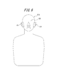
図6は、本発明の第2実施の形態に係る測定システムの要部の概略構成を示す図である。第2の実施例では、第1の実施例における耳型部50を取り付け可能な、人体の頭部模型130をさらに備える。その他の点は第1の実施例と同じでよい。頭部模型130は、例えばHATSやKEMAR(登録商標)等からなる。頭部模型130の人工耳131は、頭部模型130に対して着脱自在である。
(第2実施の形態)
図6は、本発明の第2実施の形態に係る測定システムの要部の概略構成を示す図である。第2の実施例では、第1の実施例における耳型部50を取り付け可能な、人体の頭部模型130をさらに備える。その他の点は第1の実施例と同じでよい。頭部模型130は、例えばHATSやKEMAR(登録商標)等からなる。頭部模型130の人工耳131は、頭部模型130に対して着脱自在である。
本実施の形態に係る測定システム110によると、第1実施の形態の測定システム10と同様の効果が得られる。特に、本実施の形態では、人体の頭部模型130を有することから、頭部の影響が考慮された実際の使用態様により即した評価が可能となる。尚、音響機器、電子機器を保持する保持部は実施例1と同じでよいので、図1を参照すればよい。
なお、本発明は、上記実施の形態にのみ限定されるものではなく、幾多の変形または変更が可能である。例えば、上記実施の形態では、測定対象の電子機器100として、スマートフォンのような広いパネル103を有し、パネル103が振動体として振動するものを想定したが、折り畳み式の携帯電話で、通話等の使用態様において耳に接触するパネルが振動する電子機器も同様に評価することが可能である。また、携帯電話に限らず、他の骨導方式を名乗る各種のイヤホンも同様に評価することが可能である。
また、上記実施の形態では、位相調整部430において、振動検出素子61による検出信号の位相を、マイク71による検出信号に対して遅らせるように構成したが、FIFO等のバッファを用いて、マイク71による検出信号の位相を、振動検出素子61による検出信号に対して進ませるように構成してもよい。
また、上記実施の形態では、制御部470と分離してPC500を設けるようにしたが、PC500によって実行する評価アプリケーションの機能を制御部470に搭載して、PC500を省略してもよい。
また、上述の実施例における感度調整部、信号処理部、A/D変換部、周波数特性調整部、位相調整部、出力合成部、解析部、記憶部、信号処理制御部、表示部、プリンタ等は、互いに有線通信或いは無線通信可能で信号の送信あるいは受信が可能であればよく、本発明の測定システムは、独立型ですべての機能を集約した測定装置だけでなく、感度調整部、信号処理部、解析部或いは記憶部等が一または複数のPCや外部サーバーに分かれて配置されている場合のように、ネットワークシステムやクラウドを活用した測定システムであってもよいことはいうまでもない。
上述の実施形態は代表的な例として説明したが、本発明の趣旨及び範囲内で、多くの変更及び置換ができることは当業者に明らかである。したがって、本発明は、上述の実施形態によって制限するものと解するべきではなく、特許請求の範囲から逸脱することなく、種々の変形や変更が可能である。例えば、実施形態に記載の複数の構成ブロックを1つに組み合わせたり、あるいは1つの構成ブロックを分割したりすることが可能である。また、本実施形態では、種々の動作は、プログラム命令(ソフトウェア)で実装された専用回路(たとえば、特定機能を実行するために相互接続された個別の論理ゲート)や、一以上のプロセッサにより実行される論理ブロックやプログラムモジュール等により実行されることに留意されたい。論理ブロックやプログラムモジュール等を実行する一以上のプロセッサには、たとえば、一以上のマイクロプロセッサ、CPU(中央演算処理ユニット)、ASIC(Application Specific Integrated Circuit)、DSP(Digital Signal Processor)、PLD(Programmable Logic Device)、FPGA(Field Programmable Gate Array)、プロセッサ、コントローラ、マイクロコントローラ、マイクロプロセッサ、電子機器、ここに記載する機能を実行可能に設計されたその他の装置及び/またはこれらいずれかの組合せが含まれる。ここに示す実施形態は、たとえば、ハードウェア、ソフトウェア、ファームウェア、ミドルウェア、マイクロコードまたはこれらいずれかの組合せにより実装される。命令は、必要なタスクを実行するためのプログラムコードまたはコードセグメントであってもよい。そして、命令は、機械読取り可能な非一時的記憶媒体その他の媒体に格納することができる。コードセグメントは、手順、関数、サブプログラム、プログラム、ルーチン、サブルーチン、モジュール、ソフトウェアパッケージ、クラスまたは命令、データ構造もしくはプログラムステートメントのいずれかの任意の組合せを示すものであってもよい。コードセグメントは、他のコードセグメントまたはハードウェア回路と、情報、データ引数、変数または記憶内容の送信及び/または受信を行い、これにより、コードセグメントが他のコードセグメントまたはハードウェア回路と接続される。
10 測定システム
30 基台
50 耳型部
51 耳模型
52 人工外耳道部
53 人工外耳道
56 人工下顎骨部
60 振動検出部
61x,y 振動検出素子
70 音圧測定部
71 マイク
72 チューブ部材
80 保持部
81 支持部
82 アーム部
83 移動調整部
100 電子機器
101 筐体
102 圧電素子
103 パネル(振動体)
110 測定システム
130 頭部模型
131 耳型部
300 信号分析部
410 A/D変換部
415 感度調整部
420 周波数特性調整部
425 出力合成部
430 位相調整部
440 出力合成部
450 解析部
460 記憶部
470 制御部
500 PC
520 表示部
30 基台
50 耳型部
51 耳模型
52 人工外耳道部
53 人工外耳道
56 人工下顎骨部
60 振動検出部
61x,y 振動検出素子
70 音圧測定部
71 マイク
72 チューブ部材
80 保持部
81 支持部
82 アーム部
83 移動調整部
100 電子機器
101 筐体
102 圧電素子
103 パネル(振動体)
110 測定システム
130 頭部模型
131 耳型部
300 信号分析部
410 A/D変換部
415 感度調整部
420 周波数特性調整部
425 出力合成部
430 位相調整部
440 出力合成部
450 解析部
460 記憶部
470 制御部
500 PC
520 表示部
Claims (20)
- 振動体を人体の耳に押し当てて、前記振動体の振動に基づく音をユーザに伝える電子機器を評価するための測定システムであって、
人体の耳を模した耳模型、及び、該耳模型から延在する人工外耳道を構成する人工外耳道部を含む耳型部と、
前記耳型部において、平面視で、前記人工外耳道部と並んで配置される人工下顎骨部と、
前記人工下顎骨部における、前記耳模型とは逆側の面に配置され、前記人工下顎骨部に伝達された振動を検出して出力する振動検出部と、
を備える測定システム。 - 前記耳模型或いは前記人工外耳道の少なくとも一方が振動して生成された気導成分の音圧を検出して出力する音圧測定部をさらに備える請求項1に記載の測定システム。
- 平面視における人工外耳道部の周囲で、且つ前記人工下顎骨部がない位置において、前記耳模型とは逆側の面に配置され、前記耳介に伝達された振動を検出して出力する第2の振動検出部をさらに備える請求項1に記載の測定システム。
- 検出された各出力の位相を相対的に調整可能な位相調整部を備える請求項2に記載の測定システム。
- 各出力を合成する出力合成部をさらに備える請求項2に記載の測定システム。
- 検出された出力の周波数特性を解析する解析部を備える請求項1に記載の測定システム。
- 各出力が合成された結果の出力における周波数特性を解析する解析部を備える請求項5に記載の測定システム。
- 前記振動検出部の感度を調整可能な感度調整部をさらに備える、請求項1に記載の測定システム。
- 前記音圧測定部の感度を調整可能な感度調整部をさらに備える、請求項2に記載の測定システム。
- 前記第2の振動検出部の感度を調整可能な感度調整部をさらに備える、請求項3に記載の測定システム。
- 解析結果を表示する表示部をさらに備える、請求項1に記載の測定システム。
- 人体の頭部模型をさらに備え、前記耳型部は、前記頭部模型を構成する人工耳として、当該頭部模型に着脱自在である、請求項1に記載の測定システム。
- 前記耳型部の人工外耳道は、26mmから40mmの長さを有する、請求項1に記載の測定システム。
- 前記電子機器を保持する保持部をさらに備える、請求項1に記載の測定システム。
- 前記保持部は、前記振動体を前記耳型部に対して0Nから10Nの範囲で押圧力を調整可能である、請求項14に記載の測定システム。
- 前記耳型部は、IEC60318‐7に準拠した素材からなる、請求項1に記載の測定システム。
- 前記音圧測定部は、前記人工外耳道の外壁から延在するチューブ部材に保持されたマイクを備える、請求項1に記載の測定システム。
- 前記音圧測定部は、前記人工外耳道の外壁からフローティング状態で配置されたマイクを備える、請求項1に記載の測定システム。
- 振動体を人体に押し当てて、前記振動体の振動に基づく音をユーザに伝える電子機器を評価するにあたり、
耳型部における人体の耳を模した耳模型に前記振動体を接触させるステップと、
前記耳型部において、人工外耳道部に並んで配置された人工下顎骨部に伝達された振動を、前記耳模型とは逆側の前記人工外耳道に交差する面に配置された振動検出部により検出するステップと、を含む、測定方法。 - 耳模型或いは人工外耳道の少なくとも一方が振動して生成された気導成分の音圧を測定するステップをさらに含む請求項19に記載の測定方法。
Priority Applications (1)
| Application Number | Priority Date | Filing Date | Title |
|---|---|---|---|
| US15/107,508 US10175097B2 (en) | 2013-12-26 | 2014-12-08 | Measurement system and measurement unit |
Applications Claiming Priority (2)
| Application Number | Priority Date | Filing Date | Title |
|---|---|---|---|
| JP2013270041A JP6243223B2 (ja) | 2013-12-26 | 2013-12-26 | 測定システム及び測定方法 |
| JP2013-270041 | 2013-12-26 |
Publications (1)
| Publication Number | Publication Date |
|---|---|
| WO2015098009A1 true WO2015098009A1 (ja) | 2015-07-02 |
Family
ID=53477916
Family Applications (1)
| Application Number | Title | Priority Date | Filing Date |
|---|---|---|---|
| PCT/JP2014/006121 Ceased WO2015098009A1 (ja) | 2013-12-26 | 2014-12-08 | 測定システム及び測定方法 |
Country Status (3)
| Country | Link |
|---|---|
| US (1) | US10175097B2 (ja) |
| JP (1) | JP6243223B2 (ja) |
| WO (1) | WO2015098009A1 (ja) |
Families Citing this family (3)
| Publication number | Priority date | Publication date | Assignee | Title |
|---|---|---|---|---|
| RU2754382C1 (ru) * | 2018-06-15 | 2021-09-01 | Шэньчжэнь Вокстек Ко., Лтд. | Динамик на основе костной проводимости и способ его тестирования |
| CN121099230A (zh) | 2020-03-31 | 2025-12-09 | 深圳市韶音科技有限公司 | 声学输出设备 |
| CN114760553B (zh) * | 2021-01-11 | 2026-03-27 | 深圳市韶音科技有限公司 | 一种优化骨传导耳机工作状态的方法 |
Citations (4)
| Publication number | Priority date | Publication date | Assignee | Title |
|---|---|---|---|---|
| JPS58198338A (ja) * | 1982-05-17 | 1983-11-18 | 株式会社日立製作所 | 人工耳 |
| JPH03168000A (ja) * | 1989-11-28 | 1991-07-19 | Nissan Motor Co Ltd | ダミーヘッドマイクロホン |
| JPH0638359U (ja) * | 1992-10-14 | 1994-05-20 | ユニデン株式会社 | 送受器の音量測定装置 |
| JPH11500284A (ja) * | 1995-02-16 | 1999-01-06 | ラーソン−デイヴィス・インコーポレーテッド | ヒトの乳様突起をシュミレートする装置及び方法 |
Family Cites Families (4)
| Publication number | Priority date | Publication date | Assignee | Title |
|---|---|---|---|---|
| JP2005348193A (ja) | 2004-06-04 | 2005-12-15 | Nec Tokin Corp | 受話器 |
| EP2884769B1 (en) * | 2012-05-18 | 2016-12-07 | Kyocera Corporation | Measuring apparatus, measuring system and measuring method |
| EP2925022A4 (en) * | 2012-11-22 | 2016-06-22 | Kyocera Corp | EARMODE, ARTICLE HEAD, AND MEASURING DEVICE AND METHOD USING THE EARMODEL AND THE ARTICLE HEAD |
| JP6352678B2 (ja) * | 2013-08-28 | 2018-07-04 | 京セラ株式会社 | 耳型部、人工頭部及びこれらを用いた測定装置ならびに測定方法 |
-
2013
- 2013-12-26 JP JP2013270041A patent/JP6243223B2/ja active Active
-
2014
- 2014-12-08 WO PCT/JP2014/006121 patent/WO2015098009A1/ja not_active Ceased
- 2014-12-08 US US15/107,508 patent/US10175097B2/en not_active Expired - Fee Related
Patent Citations (4)
| Publication number | Priority date | Publication date | Assignee | Title |
|---|---|---|---|---|
| JPS58198338A (ja) * | 1982-05-17 | 1983-11-18 | 株式会社日立製作所 | 人工耳 |
| JPH03168000A (ja) * | 1989-11-28 | 1991-07-19 | Nissan Motor Co Ltd | ダミーヘッドマイクロホン |
| JPH0638359U (ja) * | 1992-10-14 | 1994-05-20 | ユニデン株式会社 | 送受器の音量測定装置 |
| JPH11500284A (ja) * | 1995-02-16 | 1999-01-06 | ラーソン−デイヴィス・インコーポレーテッド | ヒトの乳様突起をシュミレートする装置及び方法 |
Also Published As
| Publication number | Publication date |
|---|---|
| JP6243223B2 (ja) | 2017-12-06 |
| US20160320233A1 (en) | 2016-11-03 |
| US10175097B2 (en) | 2019-01-08 |
| JP2015126408A (ja) | 2015-07-06 |
Similar Documents
| Publication | Publication Date | Title |
|---|---|---|
| CN103988485B (zh) | 测量设备、测量系统及测量方法 | |
| EP3016410B1 (en) | Measurement device and measurement system | |
| WO2014064924A1 (ja) | 振動ピックアップ装置、振動測定装置、測定システム及び測定方法 | |
| US10237667B2 (en) | Measurement system and measurement method | |
| JP6234082B2 (ja) | 計測システム | |
| JP6243223B2 (ja) | 測定システム及び測定方法 | |
| JP6234039B2 (ja) | 測定装置及び測定方法 | |
| JP6154434B2 (ja) | 測定システム及び測定方法 | |
| JP5474137B2 (ja) | 測定システム及び測定方法 | |
| JP5474138B2 (ja) | 測定システム及び測定方法 | |
| JP5502166B2 (ja) | 測定装置及び測定方法 | |
| WO2015011891A1 (ja) | 測定システム | |
| JP6250774B2 (ja) | 測定装置 | |
| JP6228737B2 (ja) | 測定システム及び測定方法 | |
| JP6266249B2 (ja) | 測定システム | |
| JP6161555B2 (ja) | 測定装置 | |
| JP5519739B2 (ja) | 測定システム | |
| JP6234081B2 (ja) | 測定装置 | |
| JP2014140223A (ja) | 測定システム |
Legal Events
| Date | Code | Title | Description |
|---|---|---|---|
| 121 | Ep: the epo has been informed by wipo that ep was designated in this application |
Ref document number: 14873150 Country of ref document: EP Kind code of ref document: A1 |
|
| WWE | Wipo information: entry into national phase |
Ref document number: 15107508 Country of ref document: US |
|
| NENP | Non-entry into the national phase |
Ref country code: DE |
|
| 122 | Ep: pct application non-entry in european phase |
Ref document number: 14873150 Country of ref document: EP Kind code of ref document: A1 |