WO2015093619A1 - Heat exchanger member and heat exchanger - Google Patents
Heat exchanger member and heat exchanger Download PDFInfo
- Publication number
- WO2015093619A1 WO2015093619A1 PCT/JP2014/083951 JP2014083951W WO2015093619A1 WO 2015093619 A1 WO2015093619 A1 WO 2015093619A1 JP 2014083951 W JP2014083951 W JP 2014083951W WO 2015093619 A1 WO2015093619 A1 WO 2015093619A1
- Authority
- WO
- WIPO (PCT)
- Prior art keywords
- heat exchange
- flow path
- fluid
- heat exchanger
- flow
- Prior art date
Links
Images


Classifications
-
- F—MECHANICAL ENGINEERING; LIGHTING; HEATING; WEAPONS; BLASTING
- F28—HEAT EXCHANGE IN GENERAL
- F28D—HEAT-EXCHANGE APPARATUS, NOT PROVIDED FOR IN ANOTHER SUBCLASS, IN WHICH THE HEAT-EXCHANGE MEDIA DO NOT COME INTO DIRECT CONTACT
- F28D1/00—Heat-exchange apparatus having stationary conduit assemblies for one heat-exchange medium only, the media being in contact with different sides of the conduit wall, in which the other heat-exchange medium is a large body of fluid, e.g. domestic or motor car radiators
- F28D1/02—Heat-exchange apparatus having stationary conduit assemblies for one heat-exchange medium only, the media being in contact with different sides of the conduit wall, in which the other heat-exchange medium is a large body of fluid, e.g. domestic or motor car radiators with heat-exchange conduits immersed in the body of fluid
- F28D1/04—Heat-exchange apparatus having stationary conduit assemblies for one heat-exchange medium only, the media being in contact with different sides of the conduit wall, in which the other heat-exchange medium is a large body of fluid, e.g. domestic or motor car radiators with heat-exchange conduits immersed in the body of fluid with tubular conduits
- F28D1/053—Heat-exchange apparatus having stationary conduit assemblies for one heat-exchange medium only, the media being in contact with different sides of the conduit wall, in which the other heat-exchange medium is a large body of fluid, e.g. domestic or motor car radiators with heat-exchange conduits immersed in the body of fluid with tubular conduits the conduits being straight
- F28D1/0535—Heat-exchange apparatus having stationary conduit assemblies for one heat-exchange medium only, the media being in contact with different sides of the conduit wall, in which the other heat-exchange medium is a large body of fluid, e.g. domestic or motor car radiators with heat-exchange conduits immersed in the body of fluid with tubular conduits the conduits being straight the conduits having a non-circular cross-section
- F28D1/05366—Assemblies of conduits connected to common headers, e.g. core type radiators
- F28D1/05383—Assemblies of conduits connected to common headers, e.g. core type radiators with multiple rows of conduits or with multi-channel conduits
-
- F—MECHANICAL ENGINEERING; LIGHTING; HEATING; WEAPONS; BLASTING
- F28—HEAT EXCHANGE IN GENERAL
- F28F—DETAILS OF HEAT-EXCHANGE AND HEAT-TRANSFER APPARATUS, OF GENERAL APPLICATION
- F28F1/00—Tubular elements; Assemblies of tubular elements
- F28F1/10—Tubular elements and assemblies thereof with means for increasing heat-transfer area, e.g. with fins, with projections, with recesses
- F28F1/42—Tubular elements and assemblies thereof with means for increasing heat-transfer area, e.g. with fins, with projections, with recesses the means being both outside and inside the tubular element
-
- F—MECHANICAL ENGINEERING; LIGHTING; HEATING; WEAPONS; BLASTING
- F28—HEAT EXCHANGE IN GENERAL
- F28F—DETAILS OF HEAT-EXCHANGE AND HEAT-TRANSFER APPARATUS, OF GENERAL APPLICATION
- F28F21/00—Constructions of heat-exchange apparatus characterised by the selection of particular materials
- F28F21/04—Constructions of heat-exchange apparatus characterised by the selection of particular materials of ceramic; of concrete; of natural stone
-
- F—MECHANICAL ENGINEERING; LIGHTING; HEATING; WEAPONS; BLASTING
- F28—HEAT EXCHANGE IN GENERAL
- F28F—DETAILS OF HEAT-EXCHANGE AND HEAT-TRANSFER APPARATUS, OF GENERAL APPLICATION
- F28F1/00—Tubular elements; Assemblies of tubular elements
- F28F1/02—Tubular elements of cross-section which is non-circular
- F28F2001/027—Tubular elements of cross-section which is non-circular with dimples
-
- F—MECHANICAL ENGINEERING; LIGHTING; HEATING; WEAPONS; BLASTING
- F28—HEAT EXCHANGE IN GENERAL
- F28F—DETAILS OF HEAT-EXCHANGE AND HEAT-TRANSFER APPARATUS, OF GENERAL APPLICATION
- F28F2255/00—Heat exchanger elements made of materials having special features or resulting from particular manufacturing processes
- F28F2255/18—Heat exchanger elements made of materials having special features or resulting from particular manufacturing processes sintered
Definitions
- the present invention relates to a heat exchange member and a heat exchanger.
- heat exchangers used for various cooling systems and the like have been exemplified.
- a heat exchanger for example, a plurality of long plates arranged substantially in parallel and slits between the long plates are provided, and recesses are continuously provided in the longitudinal direction on several surfaces of the long plates.
- a plurality of stacked substrates, the long plates of the adjacent substrates are connected to each other to form a tube, the recess forms an in-tube flow path, and the slit forms an out-tube flow path.
- the exchanger is illustrated (for example, refer patent document 1).
- an object of the present invention is to provide a heat exchange member with improved heat exchange efficiency and a heat exchanger provided with the same.
- the heat exchange member of the present invention includes a lid part, a bottom plate part, and a plurality of partition walls provided so as to connect the lid part and the bottom plate part.
- the portion surrounded by the bottom plate portion and the partition wall portion is a heat exchange member that is a first flow path through which the first fluid flows, and is a cross-sectional view perpendicular to the direction in which the first fluid flows.
- a curved portion that is curved toward the first flow channel is provided on at least one of the lid body and the bottom plate portion on the first flow channel side.
- the heat exchanger according to the present invention includes a plurality of flow path members through which the first fluid, which is arranged with a space therebetween, and communicates with the first flow path on one end side of each of the flow path members. And an introduction member for introducing the first fluid into the flow path member, and the first flow path at the other end of each of the flow path members. And a space through which the second fluid flows, wherein at least one of the flow path members is composed of a heat exchange member having the above-described configuration.
- the heat exchange member having improved heat exchange efficiency can be obtained by providing the curved portion.
- At least one of the flow path members through which the first fluid flows is composed of the heat exchange member having the above-described configuration, whereby the heat exchanger has improved heat exchange efficiency. be able to.
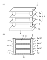
- FIG.1 (a) is an external appearance perspective view which shows an example of the heat exchanger of this embodiment
- FIG.1 (b) is sectional drawing.
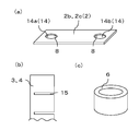
- 2 (a) to 2 (c) are excerpts showing members constituting the heat exchanger shown in FIG. 1
- FIG. 2 (a) is a perspective view showing an example of the heat exchange member.
- FIG. 2B is a side view showing an example of the introduction member and the lead-out member
- FIG. 2C is a perspective view showing an example of the covering member.
- FIG. 3A is a cross-sectional view showing another example of the heat exchange member of the present embodiment, which is perpendicular to the direction in which the first fluid flows
- FIG. 3B is a heat exchange member of the present embodiment.
- FIG. 4A is a cross-sectional view showing another example of the heat exchange member of the present embodiment, which is perpendicular to the direction in which the first fluid flows
- FIG. 4B is a heat exchange member of the present embodiment. It is sectional drawing perpendicular
- FIG.1 (a) is an external appearance perspective view which shows an example of the heat exchanger of this embodiment
- FIG.1 (b) is sectional drawing, and is an example of the member for heat exchange among the heat exchangers shown in FIG.
- FIG. 2A is a perspective view showing the above
- FIG. 2B is a side view showing an example of the introducing member and the leading member
- FIG. 2C is a perspective view showing an example of the covering member.
- the same numbers are assigned to the same members.
- each member is composed of a ceramic sintered body.
- a ceramic sintered body may be appropriately selected and used according to the environment of use and fluid characteristics.
- a silicon carbide based sintered body containing silicon carbide as a main component
- alumina as a main component.
- An alumina sintered body or the like can be used.
- the main component here is a component which contains 70 mass% or more among all the components which comprise a sintered compact, and if it is a silicon carbide based sintered compact, it will be silicon obtained by quantitative analysis.
- silicon carbide is the main component, and such a sintered body is referred to as a silicon carbide based sintered body.
- the silicon carbide sintered body has a relatively high thermal conductivity, the heat exchange efficiency of the heat exchanger can be increased, and the alumina sintered body has a low raw material cost and a silicon carbide sintered body. Since it is easier to process than a non-oxide sintered body such as a bonded body, a heat exchanger can be manufactured at a relatively low cost.
- the heat exchanger 1 in the example shown in FIG. 1 includes the heat exchange member 2 of the present embodiment as a flow path member having a first flow path 8 through which a first fluid flows.
- the heat exchanger 1 in the example shown in FIG. 1 demonstrates as all the flow-path members with which the heat exchanger 1 is provided are the members 2 for heat exchange of this embodiment.
- the heat exchanger 1 of the present embodiment includes three heat exchange members 2 through which a first fluid, which is arranged with a space between each other, and a first flow path on one end side of each heat exchange member 2.
- the above-described space serves as the second flow path 10 through which the second fluid flows.
- the one end side and the other end side mean the one end side and the other end side along the direction in which the first fluid flows.
- the first fluid and the second fluid can be appropriately used according to the purpose, such as liquid or gas.
- the first fluid is a refrigerant composed of a liquid
- the second fluid is a high-temperature gas or the like. If gas is used, heat exchange can be performed via the heat exchange member 2.
- the heat exchange member 2 since the heat exchange member 2 needs to communicate with the introduction member 3 and the lead-out member 4, the heat exchange member 2 has openings for communicating with the introduction member 3 and the lead-out member 4, respectively.
- the heat exchange member 2a disposed in the upper stage has openings on only the lower surface side, and the heat exchange members 2b and 2c disposed in the middle and lower stages. Has openings on the upper surface side and the lower surface side.
- the introduction member 3 and the lead-out member 4 are configured by one cylindrical member (for example, a cylindrical shape), the first flowing through the lead-in member 3 and the lead-out member 4 It is possible to effectively suppress the leakage of the fluid. And when the introduction member 3 and the derivation
- the introduction member 3 and the lead-out member 4 are not limited to those that extend over the plurality of heat exchange members 2, but may be simple cylinders that are individually disposed between the heat exchange members 2. Needless to say, it is good.
- connection portion between the introduction member 3 and the first flow path 8 and the connection portion between the first flow path 8 and the lead-out member 4 leak the first fluid to the outside.
- the first fluid leaks to the outside, the heat exchange efficiency is lowered, and depending on the type of the first fluid, there is a risk of adversely affecting various devices in which the heat exchanger 1 is disposed. There is.
- FIG. 1 it is disposed between the heat exchange members 2, covers the outer periphery of each of the introduction member 3 and the lead-out member 4, and one end face and the other end face are connected to the heat exchange member 2.
- a covering member 6 is preferably provided.
- the shape of the covering member 6 may be a cylindrical shape that can cover the outer periphery of each of the introduction member 3 and the lead-out member 4, and may be any single shape or combination.
- FIG. 2C shows a single cylindrical covering member 6 as an example.
- the covering member 6 when the covering member 6 is provided, the possibility that the first fluid leaks to the outside can be reduced, so that the heat exchange efficiency does not decrease and the heat exchanger 1 has improved reliability. It can be.
- FIG. 1B shows an example in which the inner surface of the covering member 6 is in contact with the outer surfaces of the introduction member 3 and the lead-out member 4, but it is not necessarily in contact, for example,
- the inner surface of the covering member 6 and the outer surfaces of the introduction member 3 and the lead-out member 4 may be arranged with a gap therebetween.
- the gap serves as a reservoir for holding the first fluid leaked.
- an introduction part 11 for introducing the first fluid into the introduction member 3 and a collection part 12 for collecting the first fluid flowing through the lead-out member 4 are provided.
- the example which has the flange part 5 provided is shown.
- the first fluid introduced from the one introduction part 11 of the flange part 5 flows through the inlet channel 7, the first channel 8, and the outlet channel 9, It is discharged from the outlet 13 via the collecting unit 12.
- the introduction part 11 and the collection part 12 should just be provided independently so that each may not mix.
- transducing part 11 and the collection part 12 may form the mutually independent flow path,
- size can be set suitably.
- the apparatus has a plurality of heat exchange members 2
- the first fluid flowing through the inlet channel 7 flows evenly through the first channels 8 of the heat exchanger members 2a to 2c.
- a plate-like flow rate extending toward the inlet side of the inlet channel 7 to the end of the first channel 8 on the introduction member 3 side, the inside of the through hole 14, the inside of the introduction member 3, or the like
- An adjustment member may be provided.
- FIG. 1 (b) shows an example in which the inlet channel 7 is formed with the same width, but the first fluid flowing through the inlet channel 7 is connected to each of the heat exchanger members 2a to 2c.
- the width of the first flow path 7 may be narrowed or widened from the first fluid inlet side to the outlet side.
- FIGS. 1 (a) and 1 (b) an example is shown in which one inlet channel 7 and one outlet channel 8 are provided.
- a plurality of inlet channels 7 and outlet channels 8 can be provided by increasing the number of openings and using the introduction member 3 and the outlet member 4 corresponding thereto.
- the first fluid and the second fluid are arranged so as to face each other. It is not necessary to arrange them, and for example, they can be arranged in accordance with the intended fluid flow, for example, arranged in a cross flow or arranged so that the flow of fluid is in the same direction.
- the use of the heat exchanger 1 described above is not particularly limited, and for example, in addition to various laser apparatuses, any apparatus that performs heat exchange can be applied as appropriate.
- all the flow path members included in the heat exchanger 1 have been described as being the heat exchange member 2 of the present embodiment, but at least one of the flow path members constituting the heat exchanger 1 is It goes without saying that the same effects described below can be obtained by comprising the heat exchange member 2 of the present embodiment.
- FIG. 3A and FIG. 3B are cross-sectional views perpendicular to the flowing direction of the first fluid, showing an example of the heat exchange member of the present embodiment.
- FIG. 3A and FIG. 3B attaches
- the heat exchange member 2d shown in FIG. 3A and the heat exchange member 2e shown in FIG. 3B connect the lid body portion 16, the bottom plate portion 17, and the lid body portion 16 and the bottom plate portion 17.
- the partition 18 provided in this manner is provided, and the portion surrounded by the lid 16, the bottom plate 17, and the partition 18 serves as the first flow path 8 through which the first fluid flows. .
- FIG. 3A and FIG. 3B for convenience, the boundary between the lid body portion 16 and the partition wall portion 18 and the bottom plate portion 17 and the partition wall portion 18 is indicated by a broken line.
- first flow paths 8 show an example in which five first flow paths 8 are provided
- the number of first flow paths 8 is not particularly limited. May be six or more, and can be set as appropriate in accordance with the required heat exchange performance.
- the partition wall 18 extends from one end side to the other end side along the direction in which the first fluid flows in the first flow path 8, whereby the first fluid, the partition wall 18, It is possible to increase the surface area that comes in contact with and improve the heat exchange efficiency.
- the first flow path 8 side of at least one of the lid body portion 16 and the bottom plate portion 17 in the cross section perpendicular to the flow direction of the first fluid A curved portion 19 that is curved toward one flow path 8 is provided.
- 3A shows an example in which only the lid portion 16 is provided
- FIG. 3B shows an example in which both the lid portion 16 and the bottom plate portion 17 are provided with a curved portion 19.
- the curved portion 19 may be provided only in the bottom plate portion 17.
- the second fluid flows on the outer surface side of the lid portion 16
- the second fluid flows along the curved portion 19 when the flow of the second fluid follows the flow of the first fluid. This facilitates the flow of the second fluid and improves the heat exchange efficiency.
- the flow of the second fluid is perpendicular to the flow of the first fluid, when the second fluid that has entered the bending portion 19 and is heat-exchanged exits the bending portion 19, Heat exchange is performed when it comes into contact with the second fluid passing therethrough, and the heat exchange efficiency is improved.
- FIG. 3A the portion directly above all the first flow paths 8 of the lid body portion 16, and in FIG. 3B, directly above all the first flow paths 8 of the lid body portion 16.
- FIG. 3B the portion directly above all the first flow paths 8 of the lid body portion 16.
- the bending degree of the bending portion 19 can be appropriately set in consideration of the strength of the lid body portion 16 and the bottom plate portion 17.
- the extension of the inner surface of the partition wall 18 is the starting point of each of the curved portions 19, and the length connecting these straight lines is defined as X, and the length of the perpendicular from the apex of the curved portion 19 to the straight line is defined as X.
- Y it is preferable that Y / X be in the range of 1 ⁇ 10 ⁇ 4 to 5 ⁇ 10 ⁇ 2 . Specifically, when X is 20 mm, Y is 2 ⁇ m to 1 mm.
- the bending degree (Y / X) of the bending part 19 mentioned above it measures from one starting point of the bending part 19 to the other starting point using a commercially available contour shape measuring instrument, for example, between starting points Can be calculated by measuring the length (X) of the straight line connecting the two, measuring the length (Y) of the perpendicular from the apex of the bending portion 19 to the straight line, and calculating using these values.
- FIG. 4A and FIG. 4B are cross-sectional views perpendicular to the flowing direction of the first fluid, showing another example of the present embodiment.
- the heat exchange member 2 there is one portion that serves as an inlet and an outlet for the first fluid, and a plurality of first flow paths 8, for example, as shown in FIGS. 4A and 4B.
- the length of the first flow path 8 located outside is set to the inside. It becomes longer than the length of the channel of the 1st channel 8 located.
- the flow rate of the first fluid flowing through each first flow path 8 is likely to be different between the outside and the inside, and a difference in heat exchange occurs between the outside and the inside, and the temperature distribution in the heat exchange member 2 May occur.
- the bending degree of the bending portion 19c positioned on the outside is inward as in the heat exchange member 2f shown in FIG.
- the temperature distribution difference can be reduced by adopting a configuration that is larger than the bending degree of the bending portion 19d.
- the relationship is Y1 ⁇ Y2.
- FIG. 4A shows an example in which the degree of curvature of the outermost bending part 19c is larger than the degree of curvature of the inner bending part 19d, but gradually curves from the outside to the inside. The degree may be reduced.
- FIG. 4B shows an example in which the bending degree of the bending part 19e located in the center, which is the innermost side, is larger than the bending degree of the bending part 19f located on the outer side.
- a configuration in which the degree of curvature gradually decreases may be adopted.
- the heat exchanger 1 according to the present embodiment is configured such that at least one of the flow path members whose inside is the first flow path 8 through which the first fluid flows is composed of the heat exchange member 2 according to the present embodiment. It has excellent heat exchange efficiency. Moreover, it is preferable that all the flow path members are composed of the heat exchange member 2 of the present embodiment. Further, all of the flow path members 2 constituting the heat exchanger 1 of the present embodiment may be composed of the heat exchange member 2 including the curved portion 19 in both the lid portion 16 and the bottom plate portion 17. Is preferred.
- a slurry is prepared by adding a desired amount of a sintering aid, a binder, a solvent, a dispersant, and the like to a powder of a raw material (silicon carbide, alumina, etc.) as a main component.
- a ceramic green sheet is formed by a doctor blade method, and the ceramic green sheet is punched out with a mold to obtain a sheet-like molded body having a desired shape.
- it is a molded body in which only the outer shape is punched out, and a molded body in which a portion corresponding to the first flow path is punched out (molded body to be a partition wall portion).
- the molded body from which only the outer shape is punched is cut to form a curved portion, or pressed against a mold having a convex portion capable of forming a curved portion of a desired shape to form the curved portion.
- the molded object used as a cover part and / or the molded object used as a baseplate part are obtained.
- a granule can be produced by spray drying and granulating the slurry by a spray granulation method (spray dry method), and the granule can be produced by a roll compaction method. Good.
- the slurry may be adjusted to clay and produced by an extrusion molding method. Furthermore, by using a granule to form by a mechanical press method or cold isostatic pressing (CIP) method, and by performing a cutting process, a molded body that becomes a bottom plate part, a molded body that becomes a partition part, and a lid part. You may produce a molded object.
- CIP cold isostatic pressing
- the laminated molded body is It can also be formed by pressing with a mold having a convex part capable of forming a curved part of a desired shape.
- a curved part can also be produced by preparing a laminated molded body in which a curved part is not formed or a molded body obtained by an extrusion molding method, and evacuating and leaving the space serving as the first flow path. can do.
- the sintered compact used as the member for heat exchange provided with the curved part of this embodiment can be obtained by baking the molded object obtained in this way at the temperature according to the main ingredient which constitutes a raw material. it can.
- each of the introduction member, the lead-out member, the covering member, and the flange portion is individually manufactured.
- a slurry is prepared by adding a desired amount of a sintering aid, a binder, a solvent, a dispersant, and the like to a raw material (silicon carbide, alumina, etc.) powder that is a main component constituting each member. .
- a ceramic green sheet is formed by a doctor blade method, and the ceramic green sheet is punched out with a mold to obtain a sheet-like molded body having a desired shape.
- the slurry is spray-dried and granulated by spray granulation to produce granules, the ceramic green sheets are formed by roll compaction, and the ceramic green sheets are punched out with a mold.
- a sheet-like molded body having a shape may be obtained.
- the slurry mentioned above is used as an adhesive agent, and it is set as the laminated molded object by stacking a sheet-like molded object.
- the slurry may be adjusted to clay and produced by an extrusion molding method.
- the extrusion method is useful for producing cylindrical members such as the introduction member, the lead-out member, and the covering member.
- coated member, and a flange part can be obtained by baking the obtained molded object at the temperature according to the main component which comprises a raw material.
- the above-mentioned member may be formed by using a granule by a mechanical press method or a cold isostatic pressing method, and joining with a molded body or adhesion after firing.
- the introduction member 3 and the lead-out member 4 are inserted into the opening provided in the heat exchange member 2a.
- the covering member 6 is inserted into the introduction member 3 and the outlet member 4.
- the heat exchange member 2b, the covering member 6, the heat exchange member 2c, and the covering member 6 are inserted, and finally the flange portion 5 is connected.
- each member is inserted in the state which apply
- the heat exchanger 1 of this embodiment can be obtained by heat-processing what was finally produced.
- the heat exchange member 2 and the covering member 6 may be laminated, and then the introduction member 3 and the lead-out member 4 may be inserted.
- examples of the adhesive used include SiO 2 —Al 2 O 3 —B 2 O 3 —RO-based glass (R: alkaline earth), which is an inorganic adhesive having excellent heat resistance and corrosion resistance.
- Metal element) powder or paste containing ceramic powder in which metal silicon powder and silicon carbide powder are mixed may be used. If such an inorganic adhesive is used as the adhesive, the heat treatment temperature is low, so that each member constituting the heat exchanger 1 is hardly deteriorated when the heat treatment is performed, and the members are bonded firmly to each other. Therefore, the reliability of the heat exchanger 1 can be improved.
- a coating layer mainly composed of Ni, Cu, Al, or Cr is formed on the heat exchanger 1 by an electroless plating method or a plasma spraying method. It doesn't matter.
- the heat exchange members 2 having different degrees of curvature are used, or the intervals between the heat exchange members 2 are made different, so that the heat exchange members 2 are positioned at opposing portions.
- the degree of curvature may be increased or decreased.
- the heat exchange member 2 itself is used as a heat exchanger, for example, for semiconductor elements, for semiconductor manufacturing apparatuses, etc. It can also be a heat exchanger.
- Heat exchanger 2 Heat exchange member 3: Introducing member 4: Deriving member 5: Flange 6: Cover member 7: Inlet channel 8: First channel 9: Outlet channel 10: Second channel 16 : Lid part 17: Bottom plate part 18: Partition part 19: Curved part
Abstract
Description
2:熱交換用部材
3:導入部材
4:導出部材
5:フランジ部
6:被覆部材
7:入口流路
8:第1流路
9:出口流路
10:第2流路
16:蓋体部
17:底板部
18:隔壁部
19:湾曲部 1: Heat exchanger 2: Heat exchange member 3: Introducing member 4: Deriving member 5: Flange 6: Cover member 7: Inlet channel 8: First channel 9: Outlet channel 10: Second channel 16 : Lid part 17: Bottom plate part 18: Partition part 19: Curved part
Claims (9)
- 蓋体部と、底板部と、前記蓋体部と前記底板部とを接続するように設けられた複数の隔壁部とを備えるとともに、前記蓋体部と前記底板部と前記隔壁部とで囲まれた部分が、第1の流体の流れる第1流路とされている熱交換用部材であって、
前記第1の流体の流れる方向に垂直な断面視において、前記蓋体部および前記底板部のうち少なくとも一方の前記第1流路側に、前記第1流路に向けて湾曲している湾曲部を備えていることを特徴とする熱交換用部材。 A lid body portion, a bottom plate portion, and a plurality of partition wall portions provided to connect the lid body portion and the bottom plate portion, and surrounded by the lid body portion, the bottom plate portion, and the partition wall portion. The portion that is the heat exchange member that is the first flow path through which the first fluid flows,
In a cross-sectional view perpendicular to the direction in which the first fluid flows, a curved portion that is curved toward the first flow channel is provided on at least one of the lid portion and the bottom plate portion on the first flow channel side. A member for heat exchange, comprising: - 前記第1流路が3つ以上設けられており、前記第1の流体の流れる方向に垂直な断面視において、外側に位置する前記湾曲部の湾曲度が、内側に位置する前記湾曲部の湾曲度よりも大きいことを特徴とする請求項1に記載の熱交換用部材。 Three or more first flow paths are provided, and in a cross-sectional view perpendicular to the direction in which the first fluid flows, the bending degree of the bending part located outside is the bending of the bending part located inside. The heat exchange member according to claim 1, wherein the heat exchange member is larger than the degree.
- 前記第1流路が3つ以上設けられており、前記第1の流体の流れる方向に垂直な断面視において、内側に位置する前記湾曲部の湾曲度が、外側に位置する前記湾曲部の湾曲度よりも大きいことを特徴とする請求項1に記載の熱交換用部材。 Three or more first flow paths are provided, and in a cross-sectional view perpendicular to the flow direction of the first fluid, the bending degree of the bending part located inside is the bending of the bending part located outside. The heat exchange member according to claim 1, wherein the heat exchange member is larger than the degree.
- それぞれが空間を空けて配置された前記第1の流体が流れる複数の流路部材と、
それぞれの前記流路部材の一端側で前記第1流路と連通し、前記流路部材に前記第1の流体を導入するための導入部材と、
それぞれの前記流路部材の他端側で前記第1流路と連通し、前記流路部材から前記第1の流体を導出するための導出部材とを備え、
前記空間が第2の流体が流れる第2流路とされており、前記流路部材の少なくとも1つが、請求項1乃至請求項3のうちいずれかに記載の熱交換用部材からなることを特徴とする熱交換器。 A plurality of flow path members through which the first fluid is disposed, each of which is spaced from the space;
An introduction member for communicating with the first flow path at one end side of each of the flow path members and for introducing the first fluid into the flow path member;
A communication member that communicates with the first flow channel at the other end of each flow channel member, and a deriving member for deriving the first fluid from the flow channel member;
The space is a second flow path through which a second fluid flows, and at least one of the flow path members includes the heat exchange member according to any one of claims 1 to 3. Heat exchanger. - 前記流路部材間に配置され、前記導入部材および前記導出部材のそれぞれの外周を覆うとともに、一端面および他端面が前記流路部材と接続された被覆部材を備えることを特徴とする請求項4に記載の熱交換器。 5. A covering member disposed between the flow path members, covering the outer periphery of each of the introduction member and the lead-out member, and having one end face and the other end face connected to the flow path member. The heat exchanger as described in.
- 前記流路部材が、一端側および他端側に開口部を有しており、該開口部に前記導入部材および前記導出部材が挿入されていることを特徴とする請求項4または請求項5に記載の熱交換用部材。 6. The flow path member according to claim 4, wherein the flow path member has openings on one end side and the other end side, and the introduction member and the lead-out member are inserted into the opening portions. The member for heat exchange as described.
- 前記導入部材に前記第1の流体を導入する導入部と、前記導出部材を流れた第1の流体を収集する収集部とを備えるフランジ部を有することを特徴とする請求項4乃至請求項6のいずれかに記載の熱交換器。 7. A flange portion comprising an introduction portion for introducing the first fluid into the introduction member and a collection portion for collecting the first fluid flowing through the lead-out member. The heat exchanger in any one of.
- 前記導出部材における流路の体積が、前記導入部材における流路の体積よりも大きいことを特徴とする請求項4乃至請求項7のいずれかに記載の熱交換器。 The heat exchanger according to any one of claims 4 to 7, wherein a volume of the flow path in the lead-out member is larger than a volume of the flow path in the introduction member.
- 載置される部材との熱交換に、請求項1乃至請求項3のうちいずれかに記載の熱交換用部材を用いることを特徴とする熱交換器。 A heat exchanger according to any one of claims 1 to 3 is used for heat exchange with a member to be placed.
Priority Applications (3)
| Application Number | Priority Date | Filing Date | Title |
|---|---|---|---|
| US15/107,046 US10697707B2 (en) | 2013-12-21 | 2014-12-22 | Heat exchange member and heat exchanger |
| JP2015553634A JP6262770B2 (en) | 2013-12-21 | 2014-12-22 | Heat exchange member and heat exchanger |
| EP14871492.6A EP3091323B1 (en) | 2013-12-21 | 2014-12-22 | Heat exchanger member and heat exchanger |
Applications Claiming Priority (2)
| Application Number | Priority Date | Filing Date | Title |
|---|---|---|---|
| JP2013-264717 | 2013-12-21 | ||
| JP2013264717 | 2013-12-21 |
Publications (1)
| Publication Number | Publication Date |
|---|---|
| WO2015093619A1 true WO2015093619A1 (en) | 2015-06-25 |
Family
ID=53402956
Family Applications (1)
| Application Number | Title | Priority Date | Filing Date |
|---|---|---|---|
| PCT/JP2014/083951 WO2015093619A1 (en) | 2013-12-21 | 2014-12-22 | Heat exchanger member and heat exchanger |
Country Status (4)
| Country | Link |
|---|---|
| US (1) | US10697707B2 (en) |
| EP (1) | EP3091323B1 (en) |
| JP (1) | JP6262770B2 (en) |
| WO (1) | WO2015093619A1 (en) |
Cited By (3)
| Publication number | Priority date | Publication date | Assignee | Title |
|---|---|---|---|---|
| JP2016108170A (en) * | 2014-12-03 | 2016-06-20 | 京セラ株式会社 | Ceramic flow passage body, and heat exchanger including the same |
| WO2018139649A1 (en) * | 2017-01-30 | 2018-08-02 | 京セラ株式会社 | Heat exchanger |
| WO2024024235A1 (en) * | 2022-07-29 | 2024-02-01 | 株式会社Uacj鋳鍛 | Heat transfer plate |
Families Citing this family (2)
| Publication number | Priority date | Publication date | Assignee | Title |
|---|---|---|---|---|
| EP3176532B1 (en) * | 2014-07-29 | 2022-07-20 | Kyocera Corporation | Heat exchanger |
| CN108036668B (en) * | 2017-12-07 | 2024-03-15 | 程向锋 | Heat exchange tube, heat exchanger comprising the same and method for manufacturing the heat exchange tube |
Citations (15)
| Publication number | Priority date | Publication date | Assignee | Title |
|---|---|---|---|---|
| JPS54139351U (en) * | 1978-03-22 | 1979-09-27 | ||
| JPS57154872U (en) * | 1981-03-20 | 1982-09-29 | ||
| JPS61181210U (en) * | 1985-05-02 | 1986-11-12 | ||
| JPS6391492A (en) * | 1986-10-03 | 1988-04-22 | Nippon Denso Co Ltd | Heat exchanger |
| JPH02109177U (en) * | 1989-02-17 | 1990-08-30 | ||
| JPH04369396A (en) * | 1991-06-18 | 1992-12-22 | Showa Alum Corp | Oil cooler |
| JPH0682124A (en) * | 1992-09-04 | 1994-03-22 | Sharp Corp | Heat exchanger |
| JPH1123100A (en) * | 1997-07-04 | 1999-01-26 | Denso Corp | Heat-exchanger |
| JPH11337276A (en) * | 1998-05-22 | 1999-12-10 | Seki Thermal Kk | Laminated heat exchanger |
| JP2001174184A (en) * | 1999-12-20 | 2001-06-29 | Toray Eng Co Ltd | Heat exchanging segment and heat exchanging element for gas-to-gas, obtained by laminating the segment |
| JP2001255027A (en) * | 2000-03-09 | 2001-09-21 | Fujitsu Ltd | Closed cycle freezing apparatus and method therefor |
| FR2813663A1 (en) * | 2000-09-04 | 2002-03-08 | Didier Costes | Heat exchanger plate for radiator has a cellular channel panel with a manifold at one end for connecting the channels |
| JP2005300062A (en) | 2004-04-14 | 2005-10-27 | Matsushita Electric Ind Co Ltd | Heat exchanger and manufacturing method of the same |
| JP2006313030A (en) * | 2005-05-06 | 2006-11-16 | Mitsubishi Heavy Ind Ltd | Plate fin type heat exchanger and its manufacturing method |
| JP2009068742A (en) * | 2007-09-12 | 2009-04-02 | Sharp Corp | Heat exchanger |
Family Cites Families (16)
| Publication number | Priority date | Publication date | Assignee | Title |
|---|---|---|---|---|
| JPS6172679A (en) * | 1984-09-14 | 1986-04-14 | 株式会社日本自動車部品総合研究所 | Low thermal expansion ceramic sintered body |
| JPH02109177A (en) | 1988-10-18 | 1990-04-20 | Canon Inc | Image processor |
| DE4201791A1 (en) | 1991-06-20 | 1993-07-29 | Thermal Waerme Kaelte Klima | FLAT TUBES FOR INSTALLATION IN A FLAT TUBE HEAT EXCHANGER AND METHOD FOR SEPARATING THE FLAT TUBES |
| EP1136781A1 (en) | 1999-09-08 | 2001-09-26 | Toray Engineering Co., Ltd. | Air-to-air heat-exchange element |
| FR2799824B1 (en) | 1999-09-28 | 2002-03-22 | Valeo Thermique Moteur Sa | MULTI-CHANNEL FLAT TUBE FOR HEAT EXCHANGER, ESPECIALLY A MOTOR VEHICLE |
| JP2001201286A (en) * | 2000-01-21 | 2001-07-27 | Mitsubishi Heavy Ind Ltd | Heat exchange tube |
| KR100382523B1 (en) * | 2000-12-01 | 2003-05-09 | 엘지전자 주식회사 | a tube structure of a micro-multi channel heat exchanger |
| JP4109444B2 (en) * | 2001-11-09 | 2008-07-02 | Gac株式会社 | Heat exchanger and manufacturing method thereof |
| KR100906769B1 (en) * | 2002-01-31 | 2009-07-10 | 한라공조주식회사 | Heat exchanger tube with tumbling toy-shaped passages and heat exchanger using the same |
| CN1228591C (en) | 2002-07-12 | 2005-11-23 | 株式会社电装 | Heat exchanger for cooling air |
| WO2005100896A1 (en) | 2004-04-14 | 2005-10-27 | Matsushita Electric Industrial Co., Ltd. | Heat exchanger and method of producing the same |
| KR20070091216A (en) * | 2005-02-02 | 2007-09-07 | 캐리어 코포레이션 | Parallel flow heat exchanger with crimped channel entrance |
| US20090087604A1 (en) * | 2007-09-27 | 2009-04-02 | Graeme Stewart | Extruded tube for use in heat exchanger |
| US20090159253A1 (en) * | 2007-12-21 | 2009-06-25 | Zaiqian Hu | Heat exchanger tubes and combo-coolers including the same |
| US8776874B2 (en) * | 2007-12-30 | 2014-07-15 | Valeo, Inc. | Heat exchanger tubes and methods for enhancing thermal performance and reducing flow passage plugging |
| KR20110104675A (en) * | 2010-03-17 | 2011-09-23 | 한국원자력연구원 | Heat transfer plate and ceramic heat exchanger and manufacturing method thereof |
-
2014
- 2014-12-22 JP JP2015553634A patent/JP6262770B2/en active Active
- 2014-12-22 US US15/107,046 patent/US10697707B2/en active Active
- 2014-12-22 EP EP14871492.6A patent/EP3091323B1/en active Active
- 2014-12-22 WO PCT/JP2014/083951 patent/WO2015093619A1/en active Application Filing
Patent Citations (15)
| Publication number | Priority date | Publication date | Assignee | Title |
|---|---|---|---|---|
| JPS54139351U (en) * | 1978-03-22 | 1979-09-27 | ||
| JPS57154872U (en) * | 1981-03-20 | 1982-09-29 | ||
| JPS61181210U (en) * | 1985-05-02 | 1986-11-12 | ||
| JPS6391492A (en) * | 1986-10-03 | 1988-04-22 | Nippon Denso Co Ltd | Heat exchanger |
| JPH02109177U (en) * | 1989-02-17 | 1990-08-30 | ||
| JPH04369396A (en) * | 1991-06-18 | 1992-12-22 | Showa Alum Corp | Oil cooler |
| JPH0682124A (en) * | 1992-09-04 | 1994-03-22 | Sharp Corp | Heat exchanger |
| JPH1123100A (en) * | 1997-07-04 | 1999-01-26 | Denso Corp | Heat-exchanger |
| JPH11337276A (en) * | 1998-05-22 | 1999-12-10 | Seki Thermal Kk | Laminated heat exchanger |
| JP2001174184A (en) * | 1999-12-20 | 2001-06-29 | Toray Eng Co Ltd | Heat exchanging segment and heat exchanging element for gas-to-gas, obtained by laminating the segment |
| JP2001255027A (en) * | 2000-03-09 | 2001-09-21 | Fujitsu Ltd | Closed cycle freezing apparatus and method therefor |
| FR2813663A1 (en) * | 2000-09-04 | 2002-03-08 | Didier Costes | Heat exchanger plate for radiator has a cellular channel panel with a manifold at one end for connecting the channels |
| JP2005300062A (en) | 2004-04-14 | 2005-10-27 | Matsushita Electric Ind Co Ltd | Heat exchanger and manufacturing method of the same |
| JP2006313030A (en) * | 2005-05-06 | 2006-11-16 | Mitsubishi Heavy Ind Ltd | Plate fin type heat exchanger and its manufacturing method |
| JP2009068742A (en) * | 2007-09-12 | 2009-04-02 | Sharp Corp | Heat exchanger |
Cited By (8)
| Publication number | Priority date | Publication date | Assignee | Title |
|---|---|---|---|---|
| JP2016108170A (en) * | 2014-12-03 | 2016-06-20 | 京セラ株式会社 | Ceramic flow passage body, and heat exchanger including the same |
| WO2018139649A1 (en) * | 2017-01-30 | 2018-08-02 | 京セラ株式会社 | Heat exchanger |
| JPWO2018139649A1 (en) * | 2017-01-30 | 2019-11-14 | 京セラ株式会社 | Heat exchanger |
| JP2022008923A (en) * | 2017-01-30 | 2022-01-14 | 京セラ株式会社 | Heat exchanger |
| US11486648B2 (en) | 2017-01-30 | 2022-11-01 | Kyocera Corporation | Heat exchanger |
| JP7208326B2 (en) | 2017-01-30 | 2023-01-18 | 京セラ株式会社 | Heat exchanger |
| WO2024024235A1 (en) * | 2022-07-29 | 2024-02-01 | 株式会社Uacj鋳鍛 | Heat transfer plate |
| JP7457760B2 (en) | 2022-07-29 | 2024-03-28 | 株式会社Uacj鋳鍛 | heat transfer plate |
Also Published As
| Publication number | Publication date |
|---|---|
| US20170038148A1 (en) | 2017-02-09 |
| JPWO2015093619A1 (en) | 2017-03-23 |
| JP6262770B2 (en) | 2018-01-17 |
| EP3091323A4 (en) | 2017-11-15 |
| US10697707B2 (en) | 2020-06-30 |
| EP3091323A1 (en) | 2016-11-09 |
| EP3091323B1 (en) | 2020-07-29 |
Similar Documents
| Publication | Publication Date | Title |
|---|---|---|
| JP6262770B2 (en) | Heat exchange member and heat exchanger | |
| EP2413079B1 (en) | Ceramic heat exchanger and method for manufacturing same | |
| US6994829B2 (en) | Fluid processing device and method | |
| CN107427920B (en) | Plate heat exchanger and method for manufacturing a plate heat exchanger | |
| JP7208326B2 (en) | Heat exchanger | |
| JP6538318B2 (en) | Plate type heat exchanger with heat exchanger block joined by foam metal | |
| CN103363824B (en) | Be there is the heat-exchangers of the plate type of the multiple modules connected by sheet material band | |
| US7637313B2 (en) | Heat exchanger and its manufacturing method | |
| US20080179046A1 (en) | Water cooling apparatus | |
| CN101738125B (en) | Micro-channel heat exchanger chip and micro heat exchanger having distributed ports structure | |
| JP6272472B2 (en) | Channel member, heat exchanger using the same, and semiconductor module | |
| JP5079586B2 (en) | Metal porous body having independent flow path | |
| TWI780737B (en) | Temperature control unit | |
| JP6352696B2 (en) | Heat exchanger | |
| JPWO2016017697A1 (en) | Heat exchanger | |
| KR100473498B1 (en) | Heat exchanger with adiabatic structure and method for manufacturing thereof | |
| CN109073340B (en) | Device and system for exchanging heat with a fluid | |
| JP6980607B2 (en) | Heat exchanger and heat exchange system | |
| JP6352773B2 (en) | Heat exchange member and heat exchanger | |
| WO2019065069A1 (en) | Measurement device component | |
| CN214747461U (en) | Adapter plate for a plate heat exchanger and plate heat exchanger with such an adapter plate | |
| JP2005300062A (en) | Heat exchanger and manufacturing method of the same | |
| KR100795269B1 (en) | Heat exchanger and method of producing the same | |
| JP2018136060A (en) | Heat exchanger |
Legal Events
| Date | Code | Title | Description |
|---|---|---|---|
| 121 | Ep: the epo has been informed by wipo that ep was designated in this application |
Ref document number: 14871492 Country of ref document: EP Kind code of ref document: A1 |
|
| ENP | Entry into the national phase |
Ref document number: 2015553634 Country of ref document: JP Kind code of ref document: A |
|
| NENP | Non-entry into the national phase |
Ref country code: DE |
|
| REEP | Request for entry into the european phase |
Ref document number: 2014871492 Country of ref document: EP |
|
| WWE | Wipo information: entry into national phase |
Ref document number: 15107046 Country of ref document: US Ref document number: 2014871492 Country of ref document: EP |