WO2015087752A1 - 楕円形筒体の成形方法及び装置 - Google Patents
楕円形筒体の成形方法及び装置 Download PDFInfo
- Publication number
- WO2015087752A1 WO2015087752A1 PCT/JP2014/081953 JP2014081953W WO2015087752A1 WO 2015087752 A1 WO2015087752 A1 WO 2015087752A1 JP 2014081953 W JP2014081953 W JP 2014081953W WO 2015087752 A1 WO2015087752 A1 WO 2015087752A1
- Authority
- WO
- WIPO (PCT)
- Prior art keywords
- forming
- cylindrical body
- elliptical
- roller
- oval
- Prior art date
- Legal status (The legal status is an assumption and is not a legal conclusion. Google has not performed a legal analysis and makes no representation as to the accuracy of the status listed.)
- Ceased
Links
Images







Classifications
-
- B—PERFORMING OPERATIONS; TRANSPORTING
- B21—MECHANICAL METAL-WORKING WITHOUT ESSENTIALLY REMOVING MATERIAL; PUNCHING METAL
- B21D—WORKING OR PROCESSING OF SHEET METAL OR METAL TUBES, RODS OR PROFILES WITHOUT ESSENTIALLY REMOVING MATERIAL; PUNCHING METAL
- B21D22/00—Shaping without cutting, by stamping, spinning, or deep-drawing
- B21D22/14—Spinning
-
- B—PERFORMING OPERATIONS; TRANSPORTING
- B21—MECHANICAL METAL-WORKING WITHOUT ESSENTIALLY REMOVING MATERIAL; PUNCHING METAL
- B21D—WORKING OR PROCESSING OF SHEET METAL OR METAL TUBES, RODS OR PROFILES WITHOUT ESSENTIALLY REMOVING MATERIAL; PUNCHING METAL
- B21D41/00—Application of procedures in order to alter the diameter of tube ends
- B21D41/04—Reducing; Closing
Definitions
- the present invention relates to a method and apparatus for forming an oval cylindrical body, and more particularly, to forming a part of an elliptical cylindrical body into a circular hollow cylinder. About.
- the oval cylindrical body 301 has a roller from the outside. 303 is abutted.
- the roller 303 can not follow the shape of the elliptic cylindrical body 301, and the roller 303 idles at the short diameter portion (see FIG. 11B). That is, since the distance between the rotation axis of the oval cylindrical body 301 and the rotation axis of the roller 303 can not be changed quickly, the roller 303 abuts only on the long diameter portion and idles without contacting the short diameter portion. I will.
- a mold (mandrel) 305 is inserted into the end portion 309 of the elliptical cylindrical body 301 shown in FIG. 12, and the end portion 309 of the elliptical cylindrical body 301 is shown in FIG. As shown in FIG. And as FIG. 14 shows, the diameter of the edge part 309 shape
- the molding time of the end portion 309 can be shortened to some extent, the conveyance of the elliptical cylindrical body 301 between the process using the mold 305 and the spinning process is possible. You will need time for Therefore, the diameter reduction of the end portion 309 also takes time.
- An object of the present invention is to provide a method and an apparatus for forming an elliptical cylinder, which can reduce the time required to form a part of the elliptical cylinder into a cylindrical shape by spinning.
- elliptical does not refer to only a mathematically accurate ellipse, but includes an oval or the like.
- a first feature of the present invention is a method of forming an elliptical cylindrical body, wherein a portion of the elliptical cylindrical body is formed into a cylindrical shape by spinning, wherein the portion of the elliptical cylindrical body is formed using an inner roller.
- Oval cylinder comprising a first forming step of forming into a cylindrical shape and a second forming step of reducing the diameter of the part formed into a cylindrical shape by the first forming step using an outer roller Provide a method of shaping the body.
- the part of the oval cylinder is an end of the oval cylinder, and the inner roller is shaped so as to draw a smooth circular arc at the boundary between the end and the portion other than the end. It is preferable to have the following site.
- the second molding step be performed in parallel with the first molding step.
- the outer roller may be used in addition to the inner roller, and the part of the elliptical cylindrical body may be formed into a cylindrical shape by simultaneously using the inner roller and the outer roller. .
- the inner roller and the outer roller are moved in the axial direction of the elliptical cylinder, and the short diameter portion of the elliptical cylinder and the vicinity of the short diameter portion are cylindrical It is preferred to shape it into a shape.
- the outer roller is provided in the same installation as the inner roller, and the first forming step and the second forming step are performed in the same installation.
- the inner roller is longer than the outer roller.
- the processing area by the outer roller in the second forming step is longer than the processing area of the inner roller in the first forming step.
- a second feature of the present invention is an oval cylindrical body forming apparatus for forming a part of an oval cylindrical body into a cylindrical shape by spinning, wherein the oval cylindrical body is positioned inside the oval cylindrical body.
- the part of the oval cylinder is an end of the oval cylinder, and the inner roller is shaped so as to draw a smooth circular arc at the boundary between the end and the portion other than the end. It is preferable to have the following site.
- the outer roller and the inner roller be provided side by side in the axial direction of the elliptical cylinder and moved in the axial direction at the same speed while maintaining a constant distance.
- the outer roller may also mold the part of the elliptical cylinder into a cylindrical shape.
- the inner roller and the outer roller are movable in the axial direction of the oval cylinder, and the short diameter portion of the oval cylinder and the vicinity of the short diameter portion are formed into a cylindrical shape. .
- the inner roller is longer than the outer roller.
- the processing area of the outer roller is longer than the processing area of the inner roller.
- (A) is sectional drawing and front view which show the elliptical cylinder before a 1st shaping
- (b) is sectional drawing and front view which show the elliptical cylinder after a 1st shaping
- (A) And (b) is a front view which shows the conventional shaping
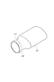
- a product (semi-finished product) 1 formed by the method of forming an oval cylindrical body according to the first embodiment is, for example, finally an exhaust gas converter or an exhaust silencer of an automobile [exhaust muffler] ] And so on.
- the product 1 includes a main body [main body] 3, an intermediate portion 5 and an end portion 7, and has a cylindrical shape [hollow cylindrical shape]. ] Is formed.
- an elliptical cylindrical (elliptical hollow cylinder) (a cylinder having an elliptical cross section orthogonal to the central axis) 9 shown in FIGS. 4 and 5 is cylindrical by spinning (perpendicular to the central axis) (A cylindrical body having a substantially circular cross section).
- the main body portion 3 maintains the shape of the elliptical cylindrical body 9.
- the end portion 7 is formed as a circular hollow cylinder portion having an outer diameter smaller than the short diameter (inner diameter) of the main body portion 3.
- the intermediate portion 5 is formed between the main body portion 3 and the end portion 7.
- the cross-sectional shape (the shape of the cross-section orthogonal to the central axis) of the intermediate portion 5 gradually moves from the cross-sectional shape of the main body portion 3 to the cross-sectional shape of the end portion 7 from the main body portion 3 to the end portion 7 Has changed.
- the central axis of the main body portion 3, the central axis of the middle portion 5, and the central axis of the end portion 7 coincide with each other.
- the direction of the central axis is referred to as an axial direction.
- the end of the elliptical cylindrical body 9 is formed into a (substantially) cylindrical shape by the inside roller 11 (first forming step).
- first forming step a large-diameter circular hollow cylindrical portion 13 is formed at the end of the elliptical cylindrical body 9.
- the outer diameter of the large-diameter cylindrical portion 13 is smaller than the long diameter (inner diameter) of the elliptical cylindrical body 9 and larger than the short diameter (outer diameter) of the elliptical cylindrical body 9.
- the outer diameter of the large-diameter cylindrical portion 13 may be larger than the major diameter (inner diameter or outer diameter) of the elliptical cylindrical body 9. Subsequently, as shown in FIG. 7, the diameter of the large-diameter cylindrical portion 13 is reduced by the pair of outside rollers 17 to form an end (a second forming step).
- the outer diameter of the end portion is smaller than the major diameter (inner diameter) of the elliptical cylindrical body 9 and larger than the minor diameter (outer diameter) of the elliptical cylindrical body 9.
- the outer roller 17 continues the spinning process, a product 1 having an end 7 whose outer diameter is smaller than the short diameter (outer diameter or inner diameter) of the elliptical cylindrical body 9 is produced (FIG. 1, FIG. 2 and FIG. 9).
- the outer diameter of the end portion 7 of the product 1 is smaller than the minor diameter (inner diameter) of the elliptical cylindrical body 9 (in the state of FIG.
- molding process is performed in parallel with a 1st shaping
- one end (right end) of the inner roller 11 is attached to an inner roller installation portion 25 described later.
- the other end (left end) of the inner roller 11 is separated from the one end (right end) of the elliptical cylindrical body 9 by the predetermined distance L0 along the above-described axial direction.
- one end (right end) of the outer roller 17 is separated from the other end (left end) of the inner roller 11 by a predetermined distance L1 along the axial direction. That is, the outer roller 17 is located on the other end side (left side) of the inner roller 11.
- the inner roller 11 is moved to one end side (right side) in the axial direction while being pressed against the inner wall of the elliptical cylindrical body 9 in a state where the elliptical cylindrical body 9 is rotated around the central axis. Be done.
- the large diameter cylindrical portion 13 is formed by the first forming step.
- the outer roller 17 is moved to one end side (right side) in the axial direction while the outer roller 17 is pressed against the outer wall of the large diameter cylindrical portion 13 in a state where the elliptical cylindrical body 9 is rotated around the central axis. Be done.
- the middle portion 5 and the end portion 7 are formed by the second molding process. At this time, the outer roller 17 moves at substantially the same speed as the inner roller 11, and follows the inner roller 11 while keeping the distance L1 to the inner roller 11 substantially constant.
- the processing area along the axial direction of the outer roller 17 used in the second forming step is longer than the processing area of the inner roller 11 used in the first forming step.
- the intermediate portion 5 is formed into an accurate shape.
- the outer roller 17 is provided in the same equipment (equipment used in spinning processing; molding apparatus) 21 as the inner roller 11. The first molding process and the second molding process are performed by the molding device 21. Also, the inner roller 11 is longer than the outer roller 17.
- the other end (left end) of the inner roller 11 is separated from the one end (right end) of the elliptical cylindrical body 9 by the predetermined distance L0 along the axial direction from the other end side (left side) . Further, one end (right end) of the inner roller 11 slightly protrudes from one end (right end) of the elliptical cylindrical body 9 along the axial direction. Therefore, a part (most part on the other end side) of the inner roller 11 enters the inside of the elliptical cylindrical body 9. In addition, the whole of the inner roller 11 may enter the inside of the elliptical cylindrical body 9, and one end of the inner roller 11 may not protrude from the elliptical cylindrical body 9.
- the length (axial length) of the outer roller 17 is shorter than the length (axial length) of the inner roller 11.
- the length of the inner roller 11 may be shortened to be approximately the same as the length of the outer roller 17. Even in this case, the predetermined distance L1 in the first molding process is maintained.
- the inner roller 11 has a shape that does not cause a defect of the product 1.
- the ridge line 315 of the mold 305 is transferred to the elliptical cylindrical body 301, Traces of ridges 315 (e.g., depressions) may remain in product 1 and cause defects.
- the ridge line [ridge line] is formed at the boundary between the solid cylindrical main body 311 of the mold 305 and the truncated-cone shaped end portion 313. ] 315 is formed.
- the ridge line 315 is transferred to the end 309
- the ridge line 317 is also formed.
- the ridge line 317 may cause a necking (e.g., a dent).
- the ridge line 317 is formed notably at the short diameter portion of the elliptical cylindrical body 301.
- the fleshiness once formed remains as a trace on the product even after the diameter of the cylindrical end 309 is reduced by the roller 303 as shown in FIG.
- the inner roller 11 of the present embodiment has a shape for avoiding such a defect.
- the inner roller 11 of the present embodiment includes a cylindrical main body 31 and a hemispherical shaped end portion 33.
- the one end () right end of the main body portion 31 is attached to the above-described inner roller installation portion 25.
- the distal end portion 33 is provided at the other end (left end) of the main body portion 31.
- the diameter of the hemisphere of the distal end portion 33 and the diameter of the main body portion 31 are equal, and the whole of the circular surface at the other end of the main body portion 31 and the entire circular plane of the distal end portion 33 are in close contact.
- the body portion 31 and the tip portion 33 are integrally formed [monolithically].
- the inner roller 11 has a smooth outer surface.
- the main body portion 31 is rectangular and the tip end portion 33 is semicircular.
- the inclination of the tangent at the cross section [outline] does not change rapidly except at the two corners on one end side (right side) of the main body 31, and changes smoothly.
- the large diameter cylindrical part 13 shown by FIG.9 (b) is formed in the edge part of the elliptical cylinder 9 shown by FIG. 9 (a) by a 1st shaping
- the boundary 15 with the [portion] 37 (portion other than the end) is shaped so as to draw a smooth arc [formed so as be smoothly curved].
- the diameter of the main body 31 is smaller than the short diameter (inner diameter) of the elliptical cylindrical body 9.
- the intermediate member [intermediary member] 35 shown in FIG. 9 (b) of the first forming step includes a non-deformed portion 37, an intermediate portion 39 and a large diameter cylindrical portion 13.
- the central axis of the non-deformed portion 37, the central axis of the middle portion 39, and the central axis of the large diameter cylindrical portion 13 coincide with each other.
- the non-deformed portion 37, the intermediate portion 39, and the large diameter cylindrical portion 13 are formed in this order.
- the non-deformed portion 37 is not subjected to any processing, and maintains the cross-sectional shape of the elliptical cylindrical body 9.
- the large diameter cylindrical portion 13 is formed in a cylindrical shape by the inner roller 11.
- the outer diameter of the large-diameter cylindrical portion 13 is smaller than the major diameter (inner diameter) of the elliptical cylindrical body 9 (non-deformed portion 37) as shown in FIGS. It is larger than the short diameter (outer diameter) of the body 9 (non-deformed portion 37).
- the outer diameter of the large-diameter cylindrical portion 13 may be larger than the major diameter (outer diameter) of the elliptical cylindrical body 9 (non-deformed portion 37).
- the cross-sectional shape of the intermediate portion 39 (the shape of the cross section orthogonal to the axial direction) is from the cross-sectional shape of the non-deformed portion 37 toward the large-diameter cylindrical portion 13 from the non-deformed portion 37 It changes smoothly and gradually as it moves to the shape.
- the boundary portion 15 corresponds to the boundary portion 41 between the large diameter cylindrical portion 13 and the middle portion 39.
- the boundary portion 15 may include the boundary portion 43 between the intermediate portion 39 and the non-deformed portion 37 and the intermediate portion 39. That is, the boundary portion 43 and the intermediate portion 39 may be formed so as to draw a smooth arc by the inner roller 11 in the first forming step.
- the tip 33 may be formed in a spherical band shape [formed to have a spherical band shape]. That is, as shown in FIG. 4, the spherical crown portion 45 may be removed from the hemispherical tip 33. Also, the tip 33 may be formed as a half-elliptical solid of revolution. In addition, the tip 33 may be formed as a truncated solid of revolution in which the top of the half of the three-dimensional oval sphere is removed.
- the boundary portion 15 is smoothly bent by providing the inner roller 11 with the tip portion 33 as a semispherical or semi-elliptical rotating body.
- the shape of the inner roller 11 may not have the outer surface continuously and smoothly formed.
- the leading end 33 of the inner roller 11 may have a gradually changing outer peripheral surface.
- the tip portion 33 shown in FIG. 10 has a shape in which a plurality of truncated cones 47 (47A, 47B, 47C, 47D) are connected.
- the tapers (gradients) of the respective truncated cones 47 (47A, 47B, 47C, 47D) are smaller as they are closer to the main body 31 (smaller in the truncated cones 47A) and larger as they are farther from the main body 31 (larger in the truncated cones 47D).
- the large diameter cylindrical portion 13 is formed by the inner roller 11 at the end of the elliptical cylindrical body 9 in the first forming step, and the large diameter cylindrical portion 13 is formed by the outer roller 17 in the second forming step. Reduce the diameter of Therefore, as compared with the case where a mold is used as in the prior art, the conveyance of the elliptic cylindrical body 9 becomes unnecessary, one step can be omitted, and the time required for molding can be shortened.
- the shape of the product 1 (size and shape of the elliptical cylindrical body 9 and size and shape of the end 7 of the elliptical cylindrical body 9) is changed Also, it is possible to cope flexibly at low cost without requiring costs such as mold production.
- the end of the elliptical cylindrical body 9 is formed into a cylindrical shape in such a manner that tensile stress, not compressive stress, acts on the end of the elliptical cylindrical body 9 in the first forming step.
- the diameter of the end formed in a cylindrical shape in which the outer roller 17 is continuously pressed against the end (large diameter cylindrical part 13) formed in the cylindrical shape of the elliptical cylindrical body 9 in the second forming step. Is reduced. Therefore, even if the spinning process in the first forming step is performed quickly, no local deformation (buckling) occurs due to compressive stress, and the end of the elliptical cylinder 9 is directly cylindrical as in the prior art.
- the time required for molding can be shortened compared to the case of molding. As a result, costs can be reduced and mass production can be facilitated.
- the second forming step is performed in parallel with the first forming step (the second forming step is performed continuously to the first forming step), the forming by the inner roller 11 is finished.
- the forming by the outer roller 17 is performed, and the end formed into a cylindrical shape by the inner roller 11 and the cylindrical roller formed by the outer roller 17 that follows the inner roller 11.
- the diameter of (large diameter cylindrical portion 13) is reduced. That is, the diameter of the portion formed in a cylindrical shape in the first molding step is reduced slightly (immediately after) in the second molding step. Therefore, the time required for molding can be further shortened.
- the outer roller 17 is provided in the same equipment as the inner roller 11, the oval cylindrical body 9 is formed between the steps (when moving from the first forming step to the second forming step). There is no need to transport, and the time required for molding can be further shortened. Moreover, since the outer roller 17 is provided in the same equipment as the inner roller 11 and the equipment of the first forming step and the equipment of the second forming step are made into one equipment, the time required for the molding can be further shortened. .
- the contact length between the elliptical cylindrical body 9 and the inner roller 11 in the first forming step can be increased, and in the first forming step Molding time can be further shortened.
- the first forming step is performed by the inner roller 11 having the hemispherical tip portion 33, it is shaped so as to draw a circular arc of the boundary portion 15 described above. Therefore, ridgelines are not transferred to the elliptical cylindrical body 9 (in particular, the inner wall thereof) by the first forming step, and no thinning occurs. Thereafter, since the diameter of the end portion formed in a cylindrical shape in the first forming step is reduced by the outer roller 17 in the second forming step, generation of defects in the product 1 can be prevented.
- the first forming step is performed only with the inner roller 11.
- the end of the elliptical cylindrical body 9 may be formed into a cylindrical shape by using the inner roller 11 and the outer roller 17 simultaneously in the first forming step (second embodiment). That is, in the first forming step, the inner roller 11 is pressed against the inner wall of the end of the oval cylindrical body 9 and at the same time the outer roller 17 is pressed against the outer wall thereof to mold the end of the oval cylindrical body 9 into a cylindrical shape May be At this time, the inner roller 11 enlarges the short diameter portion of the elliptical cylindrical body 9, and the outer roller 17 reduces the major diameter portion of the elliptical cylindrical body 9. Subsequently, in the second forming step, the diameter of the end (large diameter cylindrical portion 13) formed in a cylindrical shape in the first forming step is reduced by the outer roller 17.
- the inner roller 11 is the inner wall (in particular, the short diameter) of the elliptical cylindrical body 9 with the elliptical cylindrical body 9 rotated. (The part and its periphery) is moved to one end side (right side) in the axial direction, and the outer roller 17 is pressed against the outer wall of the elliptical cylindrical body 9 (in particular, the long diameter part and its periphery) It is moved to one end side (right side) of the direction. At this time, the outer roller 17 moves at substantially the same speed as the inner roller 11, and follows the inner roller 11 while keeping the distance L1 to the inner roller 11 substantially constant.
- the inner roller 11 is pressed against the inner wall of the elliptical cylinder 9, but the range of the pressing becomes wider as the end of the elliptical cylinder 9 approaches the cylindrical shape.
- the outer roller 17 is pressed against the outer wall of the elliptical cylinder 9, the range of pressing becomes wider as the end of the elliptical cylinder 9 approaches the cylindrical shape.
- the outer roller 17 may be disposed at the same position as the inner roller 11 along the axial direction, or disposed on one end side (right side) of the inner roller 11 in the axial direction. May be
- the outer roller 17 is at a position before the first molding step (or at a position different from the position before the first molding step, as appropriate After being returned to the position of (1), it is moved to one end side (right side) in the axial direction while being pressed against the outer wall of the elliptic cylindrical body 9.
- a second forming step is performed using another outer roller (a second outer roller provided on the same facility as the first outer roller 17) different from the outer roller (first outer roller) 17 described above. You may be performed (modification of 2nd Embodiment).
- the second outer roller is disposed at the other end side (left side) in the axial direction away from the inner roller 11 and the first outer roller 17.
- a 2nd outside roller is moved to the one end side (right side) of an axial direction, pressing on the outer wall of the elliptical cylindrical body 9.
- the second outer roller moves at substantially the same speed as the inner roller 11 and the first outer roller 17, and the inner roller 11 and the first outer roller 17 are maintained while maintaining the distance between the inner roller 11 and the first outer roller 17 substantially constant.
- the spinning process in the first forming step is further performed. It can be performed quickly, and the time required for molding can be further shortened.
- the end of the elliptical cylindrical body 9 is formed by the rollers 11 and 17, but may be formed by a spinning tool such as a spatula instead of the rollers 11 and 17.
- a spinning tool such as a spatula
- the edge part of the elliptical cylinder 9 was shape
- the above-described forming apparatus 21 includes an inner roller 11 and an outer roller 17 as shown in FIGS. 3 to 5.
- the inner roller 11 is located inside the oval cylindrical body 9 and shapes the end of the oval cylindrical body 9 into a cylindrical shape.
- the outer roller 17 is located on the outer side of the oval cylindrical body 9 and shapes the cylindrical shape formed by the inner roller 11 into a cylindrical shape with a reduced diameter.
- the forming apparatus 21 is provided with an oval cylindrical body installation unit 23, an inner roller installation unit 25, an outer roller installation unit 27, and a control unit (not shown) including a CPU.
- the elliptical cylindrical body 9 installed in the elliptical cylindrical body installation portion 23 is rotated (rotational) around its central axis.
- the inner roller 11 installed in the inner roller installation portion 25 is rotated (rotationally) about its central axis.
- the inner roller 11 is movable along a direction perpendicular to the central axis and in an axial direction, and may be fixed at an appropriate position.
- the outer roller 17 installed in the outer roller installation portion 27 is rotated (rotated) about its central axis.
- the outer roller 17 is movable along a direction perpendicular to the central axis and in an axial direction, and may be fixed at an appropriate position.
- the molding device 21 is controlled by the control unit based on an operation program stored in advance in the memory of the control unit described above, and executes the operation of the molding method described above. At this time, the forming of the product 1 by the rollers 11 and 17 is continuously performed while the state in which the elliptical cylindrical body 9 is installed in the elliptical cylindrical body installation portion 23 is maintained.
Landscapes
- Engineering & Computer Science (AREA)
- Mechanical Engineering (AREA)
- Shaping Metal By Deep-Drawing, Or The Like (AREA)
Abstract
楕円形筒体の成形方法によれば、楕円形筒体の一部がスピニング加工によって円筒形に成形される。上記成形方法は、前記楕円形筒体の前記一部を内側ローラを用いて円筒形に成形する第1成形工程と、前記第1成形工程によって円筒形に形成された前記一部の直径を、外側ローラを用いて小さくする第2成形工程と、を備える。上記成形方法によれば、スピニング加工によって楕円形筒体の一部を円筒状に成形するのに要する時間を短縮できる。
Description
本発明は、楕円形筒体の成形方法及び装置[a method and an apparatus for forming an elliptical hollow cylinder]に係り、特に、楕円形筒体の一部を円筒状[circular hollow cylinder]に成形するものに関する。
従来、スピニング加工によって楕円形筒体(ワーク)301の端部の直径を小さくして円筒状に成形する場合、図11(a)に示されるように、楕円形筒体301に、外側からローラ303が当接される。
しかし、この成形方法では、ローラ303が楕円形筒体301の形状に追従できず、短径部でローラ303が空回りしまう(図11(b)参照)。即ち、楕円形筒体301の回転軸とローラ303の回転軸との間の距離を素早く変更できないので、ローラ303が、長径部のみに当接し、短径部には当接しないで空回りしてしまう。
ローラ303が楕円形筒体301の形状に追従できるように楕円形筒体301の回転速度を遅くすると、楕円形筒体301のスピニング加工による縮径[diameter reduction]に時間がかかり過ぎ、量産化が難しくなる。そこで、楕円形筒体301の端部の縮径に要する時間を短縮する成形方法が提案されている(下記特許文献1参照)。
特許文献1に開示された成形方法では、まず、図12に示される楕円形筒体301の端部309に金型(マンドレル)305を挿入し、楕円形筒体301の端部309を図13に示されるように円筒状に成形する。そして、図14に示されるように、円筒状に成形された端部309の直径が、ローラ307を用いたスピニング加工によって小さくされ、小径端部309aが成形される。
特許文献1に開示された成形方法によれば、端部309の成形時間をある程度短縮することができるが、金型305を用いた工程とスピニング加工工程との間で楕円形筒体301の搬送のための時間が必要になる。このため、端部309の縮径にはやはり時間がかかる。
本発明の目的は、スピニング加工によって楕円形筒体の一部を円筒状に成形するのに要する時間を短縮できる、楕円形筒体の成形方法及び装置を提供することにある。なお、ここでの「楕円」とは、数学的に正確な楕円のみを指すのではなく、長円[oval]等を含む。
本発明の第1の特徴は、楕円形筒体の一部をスピニング加工によって円筒形に成形する楕円形筒体の成形方法であって、前記楕円形筒体の前記一部を内側ローラを用いて円筒形に成形する第1成形工程と、前記第1成形工程によって円筒形に形成された前記一部の直径を、外側ローラを用いて小さくする第2成形工程と、を備えた楕円形筒体の成形方法を提供する。
前記楕円形筒体の前記一部が、前記楕円形筒体の端部であり、前記内側ローラが、前記端部と該端部以外の部分との境界部を滑らかな円弧を描くように成形する部位を有している、ことが好ましい。
前記第2成形工程が、前記第1成形工程と並行して行われる、ことが好ましい。
前記第1成形工程で、前記内側ローラに加えて前記外側ローラを用いて、前記楕円形筒体の前記一部を前記内側ローラと前記外側ローラとを同時に用いて円筒形に成形してもよい。
この際、前記第1成形工程では、前記内側ローラ及び前記外側ローラが、前記楕円形筒体の軸方向に移動されて、前記楕円形筒体の短径部及び該短径部の近傍を円筒形に成形する、ことが好ましい。
前記外側ローラが、前記内側ローラと同じ設備に設けられており、前記第1成形工程及び前記第2成形工程が、前記同じ設備で行われる、ことが好ましい。
前記内側ローラが、前記外側ローラよりも長い、ことが好ましい。
前記第2成形工程での前記外側ローラによる加工領域が、前記第1成形工程での前記内側ローラの加工領域よりも長い、ことが好ましい。
本発明の第2の特徴は、楕円形筒体の一部をスピニング加工によって円筒形に成形する楕円形筒体の成形装置であって、前記楕円形筒体の内側に位置して、前記楕円形筒体の前記一部を円筒形に成形する内側ローラと、前記楕円形筒体の外側に位置して、前記内側ローラによって円筒形に形成された前記一部の直径を小さくする外側ローラと、を備えた楕円形筒体の成形装置を提供する。
前記楕円形筒体の前記一部が、前記楕円形筒体の端部であり、前記内側ローラが、前記端部と該端部以外の部分との境界部を滑らかな円弧を描くように成形する部位を有している、ことが好ましい。
前記外側ローラ及び前記内側ローラが、前記楕円形筒体の軸方向に並べて設けられて、一定の距離を保ちつつ同じ速度で前記軸方向に移動される、ことが好ましい。
前記内側ローラが前記楕円形筒体の前記一部を円筒形に成形する際に、前記外側ローラも前記楕円形筒体の前記一部を円筒形に成形するようにしてもよい。
この際、前記内側ローラ及び前記外側ローラが、前記楕円形筒体の軸方向に移動可能で、前記楕円形筒体の短径部及び該短径部近傍を円筒形に成形する、ことが好ましい。
前記内側ローラが、前記外側ローラよりも長い、ことが好ましい。
前記外側ローラの加工領域が、前記内側ローラの加工領域よりも長い、ことが好ましい。
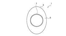
第1実施形態に係る楕円形筒体の成形方法によって成形された製品(半製品[semi-finished product])1は、例えば、最終的には、自動車の排気ガスコンバータや排気消音器[exhaust muffler]等に使用される。図1及び図2に示されるように、製品1は、本体部[main body]3と中間部[intermediary portion]5と端部[end portion]7とを備えており、筒形状[hollow cylindrical shape]を有するように形成されている。
製品1は、図4及び図5に示される楕円形筒体[elliptical hollow cylinder](中心軸に直交する楕円断面を有する筒体)9の端部が、スピニング加工によって円筒形(中心軸に直交するほぼ正円断面を有する筒体)に成形されて製造される。
本体部3は楕円形筒体9の形状を維持している。端部7は、本体部3の短径[short diameter](内径[inner diameter])よりも小さい外径を有する円筒部[circular hollow cylinder portion]として形成されている。中間部5は、本体部3と端部7との間に形成されている。中間部5の断面形状(中心軸に直交する断面の形状)は、本体部3から端部7へと向けて、本体部3の断面形状から端部7の断面形状に移行するように、徐々に変化している。また、本体部3の中心軸、中間部5の中心軸、及び、端部7の中心軸は一致する。以下、この中心軸の方向を軸方向[axial direction]と言う。
製品1の成形方法についての概略を説明する。まず、図6に示されるように、楕円形筒体9の端部が、内側ローラ[inside roller]11によって(ほぼ)円筒状に成形される(第1成形工程)。第1成形工程によって、楕円形筒体9の端部に大径円筒状部[large-diameter circular hollow cylindrical portion]13が形成される。
本実施形態では、大径円筒状部13の外径は、楕円形筒体9の長径[long diameter](内径)よりも小さく、楕円形筒体9の短径(外径)よりも大きい。しかし、大径円筒状部13の外径が、楕円形筒体9の長径(内径又は外径)より大きくされてもよい。続いて、図7に示されるように、大径円筒状部13の直径が、一対の外側ローラ[outside rollers]17によって小さくされて端部が形成される(第2成形工程)。
図7に示される状態では、端部の外径は、楕円形筒体9の長径(内径)よりも小さく、楕円形筒体9の短径(外径)よりも大きい。しかし、外側ローラ17がスピニング加工を続ければ、外径が楕円形筒体9の短径(外径又は内径)より小さい端部7を有する製品1が製造される(図1、図2及び図9参照)。なお、製品1の端部7の外径は、楕円形筒体9の短径(内径)より小さいが(図9の状態)、楕円形筒体9の長径(内径)より小さく、かつ、短径の(外径)より大きくてもよい(図7の状態)。また、後述するが、本実施形態では、第2成形工程が第1成形工程と並行して行われる(第2成形工程が第1成形工程に連続して行われる)。
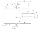
図4に示されるように、内側ローラ11の一端(右端)は、後述する内側ローラ設置部25に取り付けられている。第1成形工程以前では、内側ローラ11の他端(左端)は、上述した軸方向に沿って、楕円形筒体9の一端(右端)から他端側(左側)に所定距離L0だけ離されている。また、外側ローラ17の一端(右端)は、軸方向に沿って、内側ローラ11の他端(左端)から所定距離L1だけ離されている。即ち、外側ローラ17は、内側ローラ11よりも他端側(左側)に位置されている。
第1成形工程では、楕円形筒体9を中心軸周りに回転させた状態で、内側ローラ11が、楕円形筒体9の内壁に押し付けられつつ、軸方向の一端側(右側)へと移動される。第1成形工程によって、大径円筒状部13が形成される。第2成形工程では、楕円形筒体9を中心軸周りに回転させた状態で、外側ローラ17が大径円筒状部13の外壁に押し付けられつつ、軸方向の一端側(右側)へと移動される。第2成形工程によって、中間部5及び端部7が形成される。このとき、外側ローラ17は、内側ローラ11とほぼ同じ速度で移動し、内側ローラ11との距離L1をほぼ一定に保ったまま内側ローラ11に追従する。
第2成形工程で使用される外側ローラ17の軸方向に沿う加工領域は、第1成形工程で使用される内側ローラ11の加工領域よりも長い。このため、中間部5が、正確な形状に成形される。
外側ローラ17は、内側ローラ11と同じ設備(スピニング加工で使用される設備;成形装置)21に設けられている。第1成形工程及び第2成形工程は、成形装置21によって行われる。また、内側ローラ11は、外側ローラ17よりも長い。
第1成形工程以前では、内側ローラ11の他端(左端)は、軸方向に沿って、楕円形筒体9の一端(右端)から他端側(左側)に所定距離L0だけ離されている。また、内側ローラ11の一端(右端)は、軸方向に沿って、楕円形筒体9の一端(右端)から僅かに突出されている。従って、内側ローラ11の一部(他端側の大部分)が、楕円形筒体9の内部に入っている。なお、内側ローラ11の全体が、楕円形筒体9の内部に入っていて、内側ローラ11の一端が楕円形筒体9から突出されていなくてもよい。
外側ローラ17の長さ(軸方向の長さ)は、内側ローラ11の長さ(軸方向の長さ)よりも短い。なお、内側ローラ11の長さを短くして外側ローラ17の長さと同程度にしてもよい。この場合でも、第1成形工程における所定距離L1は維持される。
次に、本実施形態の内側ローラ11の形状について詳しく説明する。内側ローラ11は、製品1の不良を発生させない形状を有している。例えば、上述した特許文献1に開示された金型(マンドレル)305を用いた成形方法(図12~図14参照)によると、金型305の稜線315が楕円形筒体301に転写されて、稜線315の痕跡(例えば、凹み)が製品1に残って不良が発生する場合がある。
図12に示されるように、金型305の円柱状の本体部[solid cylindrical main body]311と円錐台状の先端部[truncated-cone shaped end portion]313との境界には、稜線[ridge line]315が形成されている。図13に示されるように、金型305を楕円形筒体301の端部309に挿入して楕円形筒体301の端部309を円筒形に形成すると、稜線315が転写されて端部309にも稜線317が形成される。このとき、稜線317によって肉痩せ[necking](例えば、凹み)が生じる場合がある。稜線317は、楕円形筒体301の短径部で顕著に形成される。
一度形成された肉痩せは、その後、図14に示されるようにローラ303によって円筒形の端部309の直径を小さくした後でも、製品に痕跡として残ってしまい、製品の不良となる。本実施形態の内側ローラ11は、このような不良を回避するための形状を有している。
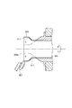
本実施形態の内側ローラ11は、図4に示されるように、円柱状の本体部31と半球状の先端部[hemispherical shaped end portion]33とを備えている。本体部31の一端()右端は、上述した内側ローラ設置部25に取り付けられている。先端部33は、本体部31の他端(左端)に設けられている。先端部33の半球の直径と本体部31の直径とは等しく、本体部31の他端の円形面の全体と、先端部33の円形平面の全面とは密着されている。あるいは、本体部31と先端部33とは一体的に[monolithically]形成される。
内側ローラ11は、滑らかな外表面を有している。内側ローラ11の断面(中心軸を含む断面)では、本体部31は長方形であり、先端部33は半円である。断面の外形[outline]での接線の傾きは、本体部31の一端側(右側)2つの角部を除いて、急激に変化することはなく、滑らかに変化する。
図9(a)に示される楕円形筒体9の端部には、第1成形工程によって、図9(b)に示される大径円筒状部13が形成される。第1成形工程では、滑らかな外表面を有する内側ローラ11(本体部31及び先端部33)によって、大径円筒状部13(楕円形筒体9の端部)と非変形部[non-deformed portion]37(端部以外の部分)との境界部15が滑らかな円弧を描くように成形される[formed so as to be smoothly curved]。なお、本体部31の直径は、楕円形筒体9の短径(内径)よりも小さい。
第1成形工程の図9(b)に示される中間体[intermediary member]35は、非変形部37と、中間部39と、大径円筒状部13とを備える。非変形部37の中心軸、中間部39の中心軸、及び、大径円筒状部13の中心軸は一致する。軸方向に沿って、非変形部37、中間部39、及び、大径円筒状部13が、この順に形成されている。
非変形部37は何らの加工が施されず、楕円形筒体9の断面形状を維持している。大径円筒状部13は、内側ローラ11によって円筒状に形成されている。大径円筒状部13の外径は、図6及び図9(b)に示されるように、楕円形筒体9(非変形部37)の長径(内径)よりも小さく、かつ、楕円形筒体9(非変形部37)の短径(外径)よりも大きい。ただし、大径円筒状部13の外径は、楕円形筒体9(非変形部37)の長径(外径)よりも大きくてもよい。
中間部39の断面形状(軸方向に直交する断面の形状)は、非変形部37から大径円筒状部13へと向けて、非変形部37の断面形状から大径円筒状部13の断面形状に移行するように、滑らかに徐々に変化している。境界部15は、大径円筒状部13と中間部39との境界部41に相当する。なお、境界部15が、中間部39と非変形部37との境界部43や、中間部39を含んでいてもよい。即ち、境界部43や中間部39が、第1成形工程で内側ローラ11によって滑らかな円弧を描くように成形されてもよい。
なお、先端部33が、球帯状に形成されてもよい[formed to have a spherical band shape]。即ち、図4中に示されるように、半球状の先端部33から球頂部[spherical crown portion]45が取り除かれてもよい。また、先端部33は、半楕円回転体[a half-elliptical solid of revolution]として形成されてもよい。また、先端部33は、立体楕円球の半分から頂部が取り除かれた帯状回転体[truncated solid of revolution]として形成されてもよい。
本実施形態では、内側ローラ11が半球体や半楕円回転体としての先端部33を備えることで、境界部15が滑らかに曲げられた。しかし、内側ローラ11の形状は、外面が連続的に滑らかに形成されていなくてもよい。例えば、図10に示されるように、内側ローラ11の先端部33は、段階的に変化する外周面を有していてもよい。
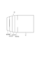
図10に示される先端部33は、複数の円錐台47(47A,47B,47C,47D)を結合した形状を有している。各円錐台47(47A,47B,47C,47D)のテーパ(勾配)は、本体部31に近いほど小さく(円錐台47Aでは小さく)、本体部31から遠いほど大きい(円錐台47Dでは大きい)。
本実施形態によれば、第1成形工程で楕円形筒体9の端部に内側ローラ11によって大径円筒状部13を形成し、第2成形工程で外側ローラ17によって大径円筒状部13の直径を小さくする。従って、従来のように金型を用いる場合に比べて、楕円形筒体9の搬送が不要になり、一工程を省略でき、成形に要する時間を短縮できる。
また、本実施形態によれば、専用の金型が不要なので、製品1の形状(楕円形筒体9の大きさや形状、楕円形筒体9の端部7の大きさや形状)が変更されても、金型製作等のコストが必要なく、低コストで柔軟に対応できる。
また、本実施形態によれば、第1成形工程で楕円形筒体9の端部に圧縮応力ではなく引張応力が作用する態様で楕円形筒体9の端部が円筒形に成形され、その後、第2成形工程で楕円形筒体9の円筒形に形成された端部(大径円筒状部13)に外側ローラ17が連続して押し付けられて、円筒形に形成された端部の直径が小さくされる。従って、第1成形工程でのスピニング加工を速く行っても、圧縮応力による局部的な変形(座屈)が生じることはなく、従来のように楕円形筒体9の端部を直接円筒形に成形する場合に比べて、成形に要する時間を短縮できる。この結果、コストを低減でき、量産化しやすくなる。
また、本実施形態によれば、第2成形工程が第1成形工程と並行して行われる(第2成形工程が第1成形工程に連続して行われる)ので、内側ローラ11による成形が終わるとすぐに外側ローラ17による成形が行われ、内側ローラ11で楕円形筒体9の端部を円筒形に成形しつつ、内側ローラ11に追従する外側ローラ17によって円筒形に成形された端部(大径円筒状部13)の直径が小さくされる。即ち、第1成形工程で円筒形に形成された部位は、わずかに遅れて(直後に)第2成形工程でその直径が小さくされる。従って、成形に要する時間をさらに短縮できる。
また、本実施形態によれば、外側ローラ17が内側ローラ11と同じ設備に設けられているので、工程間で(第1成形工程から第2成形工程に移るときに)楕円形筒体9を搬送する必要がなく、成形に要する時間をさらに短縮できる。また、外側ローラ17が内側ローラ11と同じ設備に設けられており、第1成形工程の設備と第2成形工程の設備とが1つの設備とされているので、成形に要する時間をさらに短縮できる。
また、本実施形態によれば、内側ローラ11が外側ローラ17よりも長いので、第1成形工程での楕円形筒体9と内側ローラ11との接触長さを長くでき、第1成形工程での成形時間を一層短縮することができる。
さらに、本実施形態では、半球状の先端部33を有する内側ローラ11によって第1成形工程が行われるので、上述した境界部15な円弧を描くように成形される。従って、第1成形工程によって楕円形筒体9(特に、その内壁)に、稜線が転写されて肉痩せが生じることがない。その後、第1成形工程で円筒形に形成された端部の直径が、第2成形工程で外側ローラ17によって小さくされるので、製品1に不良が発生することを防止できる。
上述した実施形態では、内側ローラ11のみで第1成形工程が実施された。しかし、第1成形工程で、内側ローラ11と外側ローラ17とを同時に用いて、楕円形筒体9の端部を円筒形に成形してもよい(第2実施形態)。即ち、第1成形工程で、楕円形筒体9の端部の内壁に内側ローラ11を押し付けると同時にその外壁に外側ローラ17を押し付けて、楕円形筒体9の端部を円筒形に成形してもよい。このとき、内側ローラ11は楕円形筒体9の短径部を拡大し、外側ローラ17は楕円形筒体9の長径部を縮小させる。続いて、第2成形工程では、第1成形工程で円筒形に形成された端部(大径円筒状部13)の直径が、外側ローラ17によって小さくされる。
第1成形工程での内側ローラ11と外側ローラ17とを同時に用いた成形では、楕円形筒体9を回転させた状態で、内側ローラ11が、楕円形筒体9の内壁(特に、短径部及びその周辺)に押し付けられつつ、軸方向の一端側(右側)に移動され、かつ、外側ローラ17が、楕円形筒体9の外壁(特に、長径部及びその周辺)に押し付けられつつ軸方向の一方端側(右側)へと移動される。このとき、外側ローラ17は、内側ローラ11とほぼ同じ速度で移動し、内側ローラ11との距離L1をほぼ一定に保ったまま内側ローラ11を追従する。
なお、内側ローラ11が楕円形筒体9の内壁に押し付けられるが、押し付けられる範囲は、楕円形筒体9の端部が円筒形に近づくにしたがって次第に広くなる。同様に、外側ローラ17が楕円形筒体9の外壁に押し付けられるが、押し付けられる範囲は、楕円形筒体9の端部が円筒形に近づくにしたがって次第に広くなる。なお、第1成形工程以前では、外側ローラ17は、軸方向に沿って、内側ローラ11と同じ位置に配されてもよいし、内側ローラ11よりも軸方向の一端側(右側)に配されてもよい。
第2成形工程での外側ローラ17を用いた成形では、外側ローラ17は、第1成形工程以前の位置(又は、第1成形工程以前の位置とは異なる位置であって、必要に応じた適宜の位置)に戻された後、楕円形筒体9の外壁に押し付けられつつ、軸方向の一端側(右側)に移動される。
なお、上述した外側ローラ(第1外側ローラ)17とは異なる別の外側ローラ(第1外側ローラ17と同じ設備に設けられた第2外側ローラ:図示せず)を用いて第2成形工程が行われてもよい(第2実施形態の変形例)。この場合、第1成形工程以前では、第2外側ローラは、軸方向の他端側(左側)に、内側ローラ11や第1外側ローラ17から離れたところに配されている。
そして、第2成形工程での第2外側ローラによる成形では、第2外側ローラは、楕円形筒体9の外壁に押し付けられつつ、軸方向の一端側(右側)へと移動される。このとき、第2外側ローラは、内側ローラ11及び第1外側ローラ17とほぼ同じ速度で移動し、内側ローラ11及び第1外側ローラ17との距離をほぼ一定に保ったまま内側ローラ11及び第1外側ローラ17に追従する。
本実施形態によれば、第1成形工程では内側ローラ11と外側ローラ17とを同時に用いて楕円形筒体9の端部を円筒形に成形するので、第1成形工程でのスピニング加工を一層速く行うことができ、成形に要する時間を一層短縮できる。
なお、上記実施形態では、楕円形筒体9の端部がローラ11及び17によって成形されたが、ローラ11及び17に代えてヘラ等のスピニング加工用ツールによって成形されてもよい。また、上記実施形態では、楕円形筒体9の端部が成形されたが、楕円形筒体9の中央等の他の部分が成形されてもよい。
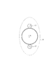
上述した成形装置21は、図3~図5に示されるように、内側ローラ11と外側ローラ17とを備えている。内側ローラ11は、楕円形筒体9の内側に位置して、楕円形筒体9の端部を円筒形に成形する。外側ローラ17は、楕円形筒体9の外側に位置して、内側ローラ11によって成形された円筒形を直径が小さくされた円筒形に成形する。また、成形装置21には、楕円形筒体設置部23と、内側ローラ設置部25と、外側ローラ設置部27と、CPUを含む制御部(図示せず)とが設けられている。
楕円形筒体設置部23に設置された楕円形筒体9は、その中心軸周りに回転(自転)される。内側ローラ設置部25に設置された内側ローラ11は、その中心軸周りに回転(自転)される。内側ローラ11は、中心軸に直交する方向及び軸方向に沿って移動可能で、適宜位置で固定され得る。外側ローラ設置部27に設置された外側ローラ17は、その中心軸周り回転(自転)される。外側ローラ17は、中心軸に直交する方向及び軸方向に沿って移動可能で、適宜位置で固定され得る。
楕円形筒体設置部23に設置された楕円形筒体9の中心軸の延伸方向と、内側ローラ設置部25に設置された内側ローラ11の中心軸の延伸方向と、外側ローラ設置部27に設置された外側ローラ17の中心軸の延伸方向とは同じである。
また、成形装置21は、上述した制御部のメモリに予め格納されている動作プログラムに基づいて制御部によって制御され、上述した成形方法の動作を実行する。このとき、ローラ11及び17による製品1の成形は、楕円形筒体9が楕円形筒体設置部23に設置された状態が維持されたまま続けて行われる。
Claims (15)
- 楕円形筒体の一部をスピニング加工によって円筒形に成形する楕円形筒体の成形方法であって、
前記楕円形筒体の前記一部を内側ローラを用いて円筒形に成形する第1成形工程と、
前記第1成形工程によって円筒形に形成された前記一部の直径を、外側ローラを用いて小さくする第2成形工程と、を備えた楕円形筒体の成形方法。 - 請求項1に記載の楕円形筒体の成形方法であって、
前記楕円形筒体の前記一部が、前記楕円形筒体の端部であり、
前記内側ローラが、前記端部と該端部以外の部分との境界部を滑らかな円弧を描くように成形する部位を有している、楕円形筒体の成形方法。 - 請求項1又は2に記載の楕円形筒体の成形方法であって、
前記第2成形工程が、前記第1成形工程と並行して行われる、楕円形筒体の成形方法。 - 請求項1に記載の楕円形筒体の成形方法であって、
前記第1成形工程で、前記内側ローラに加えて前記外側ローラを用いて、前記楕円形筒体の前記一部を前記内側ローラと前記外側ローラとを同時に用いて円筒形に成形する、楕円形筒体の成形方法。 - 請求項4に記載の楕円形筒体の成形方法であって、
前記第1成形工程では、前記内側ローラ及び前記外側ローラが、前記楕円形筒体の軸方向に移動されて、前記楕円形筒体の短径部及び該短径部の近傍を円筒形に成形する、楕円形筒体の成形方法。 - 請求項1~5のいずれか一項に記載の楕円形筒体の成形方法であって、
前記外側ローラが、前記内側ローラと同じ設備に設けられており、前記第1成形工程及び前記第2成形工程が、前記同じ設備で行われる、楕円形筒体の成形方法。 - 請求項1~6のいずれか一項に記載の楕円形筒体の成形方法であって、
前記内側ローラが、前記外側ローラよりも長い、楕円形筒体の成形方法。 - 請求項1~7のいずれか一項に記載の楕円形筒体の成形方法であって、
前記第2成形工程での前記外側ローラによる加工領域が、前記第1成形工程での前記内側ローラの加工領域よりも長い、楕円形筒体の成形方法。 - 楕円形筒体の一部をスピニング加工によって円筒形に成形する楕円形筒体の成形装置であって、
前記楕円形筒体の内側に位置して、前記楕円形筒体の前記一部を円筒形に成形する内側ローラと、
前記楕円形筒体の外側に位置して、前記内側ローラによって円筒形に形成された前記一部の直径を小さくする外側ローラと、を備えた楕円形筒体の成形装置。 - 請求項9に記載の楕円形筒体の成形装置であって、
前記楕円形筒体の前記一部が、前記楕円形筒体の端部であり、
前記内側ローラが、前記端部と該端部以外の部分との境界部を滑らかな円弧を描くように成形する部位を有している、楕円形筒体の成形装置。 - 請求項9又は10に記載の楕円形筒体の成形装置であって、
前記外側ローラ及び前記内側ローラが、前記楕円形筒体の軸方向に並べて設けられて、一定の距離を保ちつつ同じ速度で前記軸方向に移動される、楕円形筒体の成形装置。 - 請求項9に記載の楕円形筒体の成形装置であって、
前記内側ローラが前記楕円形筒体の前記一部を円筒形に成形する際に、前記外側ローラも前記楕円形筒体の前記一部を円筒形に成形する、楕円形筒体の成形装置。 - 請求項12に記載の楕円形筒体の成形装置であって、
前記内側ローラ及び前記外側ローラが、前記楕円形筒体の軸方向に移動可能で、前記楕円形筒体の短径部及び該短径部近傍を円筒形に成形する、楕円形筒体の成形装置。 - 請求項9~請求項13のいずれか一項に記載の楕円形筒体の成形装置であって、
前記内側ローラが、前記外側ローラよりも長い、楕円形筒体の成形装置。 - 請求項9~請求項14のいずれか一項に記載の楕円形筒体の成形装置であって、
前記外側ローラの加工領域が、前記内側ローラの加工領域よりも長い、楕円形筒体の成形装置。
Priority Applications (2)
| Application Number | Priority Date | Filing Date | Title |
|---|---|---|---|
| CN201480067478.4A CN105813776A (zh) | 2013-12-12 | 2014-12-03 | 椭圆形筒体的成形方法及装置 |
| US15/103,350 US9821358B2 (en) | 2013-12-12 | 2014-12-03 | Method and apparatus for forming elliptical hollow cylinder |
Applications Claiming Priority (4)
| Application Number | Priority Date | Filing Date | Title |
|---|---|---|---|
| JP2013256630A JP6278681B2 (ja) | 2013-12-12 | 2013-12-12 | 楕円形筒体の成形方法および楕円形筒体の成形装置 |
| JP2013-256630 | 2013-12-12 | ||
| JP2013266927A JP6254439B2 (ja) | 2013-12-25 | 2013-12-25 | 楕円形筒体の成形方法および楕円形筒体の成形装置 |
| JP2013-266927 | 2013-12-25 |
Publications (1)
| Publication Number | Publication Date |
|---|---|
| WO2015087752A1 true WO2015087752A1 (ja) | 2015-06-18 |
Family
ID=53371060
Family Applications (1)
| Application Number | Title | Priority Date | Filing Date |
|---|---|---|---|
| PCT/JP2014/081953 Ceased WO2015087752A1 (ja) | 2013-12-12 | 2014-12-03 | 楕円形筒体の成形方法及び装置 |
Country Status (3)
| Country | Link |
|---|---|
| US (1) | US9821358B2 (ja) |
| CN (1) | CN105813776A (ja) |
| WO (1) | WO2015087752A1 (ja) |
Cited By (1)
| Publication number | Priority date | Publication date | Assignee | Title |
|---|---|---|---|---|
| CN108698110A (zh) * | 2016-03-14 | 2018-10-23 | 川崎重工业株式会社 | 管的扩径方法及成形装置 |
Families Citing this family (3)
| Publication number | Priority date | Publication date | Assignee | Title |
|---|---|---|---|---|
| CN109290404B (zh) * | 2018-09-04 | 2020-03-31 | 陕西科技大学 | 一种椭圆筒节的卷制成型方法 |
| GB2591275B (en) * | 2020-01-23 | 2022-06-08 | Nissan Motor Mfg Uk Ltd | Method of controlling a mandrel-free spinning apparatus |
| CN117583486A (zh) * | 2024-01-19 | 2024-02-23 | 江苏国强兴晟能源科技股份有限公司 | 一种用于八角管缩口的自适应防偏移缩口机 |
Citations (6)
| Publication number | Priority date | Publication date | Assignee | Title |
|---|---|---|---|---|
| JPS63309333A (ja) * | 1987-06-09 | 1988-12-16 | Nippon Steel Corp | 管端部加工装置 |
| JPH05226U (ja) * | 1991-06-18 | 1993-01-08 | 大和工業株式会社 | 金属板の折曲加工装置 |
| JP2000246353A (ja) * | 1999-03-02 | 2000-09-12 | Toyota Motor Corp | 管の成形方法 |
| JP2002066665A (ja) * | 2000-06-15 | 2002-03-05 | Fuji Kikai Kosakusho:Kk | 筒体の加工方法 |
| JP2003230917A (ja) * | 2002-02-08 | 2003-08-19 | Toyo Seikan Kaisha Ltd | 缶胴の縮径方法及びその装置 |
| US20040011105A1 (en) * | 2000-12-01 | 2004-01-22 | Yoshinobu Nakamura | Forming method of cylindrical work piece and apparatus for it |
Family Cites Families (5)
| Publication number | Priority date | Publication date | Assignee | Title |
|---|---|---|---|---|
| JPS542262A (en) * | 1977-06-08 | 1979-01-09 | Mitsubishi Heavy Ind Ltd | Method and apparatus for roll forming |
| JP5435190B2 (ja) | 2007-03-30 | 2014-03-05 | 日立オートモティブシステムズ株式会社 | 管体の加工方法及びシリンダ装置の製造方法 |
| CN101954401B (zh) * | 2010-01-07 | 2012-03-28 | 浙江格洛斯无缝钢管有限公司 | 无缝管强力旋压方法 |
| GB201016611D0 (en) * | 2010-10-01 | 2010-11-17 | Cambridge Entpr Ltd | Spin forming and apparatus for manufacturing articles by spin forming |
| US8356506B2 (en) * | 2011-02-25 | 2013-01-22 | Szuba Consulting, Inc. | Method of forming industrial housings |
-
2014
- 2014-12-03 US US15/103,350 patent/US9821358B2/en active Active
- 2014-12-03 CN CN201480067478.4A patent/CN105813776A/zh active Pending
- 2014-12-03 WO PCT/JP2014/081953 patent/WO2015087752A1/ja not_active Ceased
Patent Citations (6)
| Publication number | Priority date | Publication date | Assignee | Title |
|---|---|---|---|---|
| JPS63309333A (ja) * | 1987-06-09 | 1988-12-16 | Nippon Steel Corp | 管端部加工装置 |
| JPH05226U (ja) * | 1991-06-18 | 1993-01-08 | 大和工業株式会社 | 金属板の折曲加工装置 |
| JP2000246353A (ja) * | 1999-03-02 | 2000-09-12 | Toyota Motor Corp | 管の成形方法 |
| JP2002066665A (ja) * | 2000-06-15 | 2002-03-05 | Fuji Kikai Kosakusho:Kk | 筒体の加工方法 |
| US20040011105A1 (en) * | 2000-12-01 | 2004-01-22 | Yoshinobu Nakamura | Forming method of cylindrical work piece and apparatus for it |
| JP2003230917A (ja) * | 2002-02-08 | 2003-08-19 | Toyo Seikan Kaisha Ltd | 缶胴の縮径方法及びその装置 |
Cited By (3)
| Publication number | Priority date | Publication date | Assignee | Title |
|---|---|---|---|---|
| CN108698110A (zh) * | 2016-03-14 | 2018-10-23 | 川崎重工业株式会社 | 管的扩径方法及成形装置 |
| JPWO2017158635A1 (ja) * | 2016-03-14 | 2019-02-14 | 川崎重工業株式会社 | 管の拡径方法および成形装置 |
| CN108698110B (zh) * | 2016-03-14 | 2019-10-08 | 川崎重工业株式会社 | 管的扩径方法及成形装置 |
Also Published As
| Publication number | Publication date |
|---|---|
| CN105813776A (zh) | 2016-07-27 |
| US9821358B2 (en) | 2017-11-21 |
| US20160325332A1 (en) | 2016-11-10 |
Similar Documents
| Publication | Publication Date | Title |
|---|---|---|
| CN103403305B (zh) | 中空发动机气门的制造方法 | |
| JP5495496B2 (ja) | 筒状ワークの端部加工方法及び装置 | |
| CN105745039B (zh) | 锻造曲轴的制造方法 | |
| CN101274347A (zh) | 管体的加工方法、油缸装置的制造方法和油缸装置 | |
| JP4647056B2 (ja) | 管の成形方法及び成形装置 | |
| JP2013538692A (ja) | スピン成形によって物品を製造するスピン成形プロセス及び装置 | |
| CN101376153A (zh) | 内齿轮的成形方法及成形装置 | |
| JP6442752B1 (ja) | ラックの製造方法、操舵装置の製造方法および車両の製造方法 | |
| CN105813776A (zh) | 椭圆形筒体的成形方法及装置 | |
| CN105764630A (zh) | 锻造曲轴的制造方法 | |
| JP6847398B2 (ja) | 逐次成形方法 | |
| JP6618940B2 (ja) | スピニング加工方法及び載頭円錐部を端部に有する筒状体 | |
| JP2017144457A (ja) | 成形装置および成形方法 | |
| JP6278681B2 (ja) | 楕円形筒体の成形方法および楕円形筒体の成形装置 | |
| JP4647140B2 (ja) | 管端の成形方法 | |
| JP6254439B2 (ja) | 楕円形筒体の成形方法および楕円形筒体の成形装置 | |
| JP6519984B2 (ja) | 同時異種加工管部材の製造方法 | |
| CN107350328B (zh) | 不同宽度横向内筋构件旋压成形的芯模及成形方法 | |
| CN111842743B (zh) | 一种管筒形工件双环辊内接触式旋轧方法 | |
| JP7078599B2 (ja) | 曲管の製造装置、及び曲管の製造方法 | |
| JP2008126236A (ja) | 塑性加工方法 | |
| CN117715711A (zh) | 供油管的制造装置以及供油管的制造方法 | |
| US10634036B2 (en) | Method for molding pipe body | |
| JPH01245914A (ja) | 外径真円度の優れた金属管の製造方法 | |
| CN104965944B (zh) | 轴管缩口模具的设计方法 |
Legal Events
| Date | Code | Title | Description |
|---|---|---|---|
| 121 | Ep: the epo has been informed by wipo that ep was designated in this application |
Ref document number: 14870026 Country of ref document: EP Kind code of ref document: A1 |
|
| WWE | Wipo information: entry into national phase |
Ref document number: 15103350 Country of ref document: US |
|
| NENP | Non-entry into the national phase |
Ref country code: DE |
|
| 122 | Ep: pct application non-entry in european phase |
Ref document number: 14870026 Country of ref document: EP Kind code of ref document: A1 |