WO2015087701A1 - プリーツフィルター、それを用いたバラスト水処理装置およびバラスト水の処理方法 - Google Patents
プリーツフィルター、それを用いたバラスト水処理装置およびバラスト水の処理方法 Download PDFInfo
- Publication number
- WO2015087701A1 WO2015087701A1 PCT/JP2014/081301 JP2014081301W WO2015087701A1 WO 2015087701 A1 WO2015087701 A1 WO 2015087701A1 JP 2014081301 W JP2014081301 W JP 2014081301W WO 2015087701 A1 WO2015087701 A1 WO 2015087701A1
- Authority
- WO
- WIPO (PCT)
- Prior art keywords
- filter
- reinforcing plate
- pleated filter
- ballast water
- pleat
- Prior art date
- Legal status (The legal status is an assumption and is not a legal conclusion. Google has not performed a legal analysis and makes no representation as to the accuracy of the status listed.)
- Ceased
Links
Images


Classifications
-
- B—PERFORMING OPERATIONS; TRANSPORTING
- B01—PHYSICAL OR CHEMICAL PROCESSES OR APPARATUS IN GENERAL
- B01D—SEPARATION
- B01D33/00—Filters with filtering elements which move during the filtering operation
- B01D33/06—Filters with filtering elements which move during the filtering operation with rotary cylindrical filtering surfaces, e.g. hollow drums
- B01D33/073—Filters with filtering elements which move during the filtering operation with rotary cylindrical filtering surfaces, e.g. hollow drums arranged for inward flow filtration
-
- B—PERFORMING OPERATIONS; TRANSPORTING
- B01—PHYSICAL OR CHEMICAL PROCESSES OR APPARATUS IN GENERAL
- B01D—SEPARATION
- B01D33/00—Filters with filtering elements which move during the filtering operation
- B01D33/44—Regenerating the filter material in the filter
- B01D33/48—Regenerating the filter material in the filter by flushing, e.g. counter-current air-bumps
- B01D33/50—Regenerating the filter material in the filter by flushing, e.g. counter-current air-bumps with backwash arms, shoes or nozzles
- B01D33/503—Regenerating the filter material in the filter by flushing, e.g. counter-current air-bumps with backwash arms, shoes or nozzles the backwash arms, shoes acting on the cake side
-
- B—PERFORMING OPERATIONS; TRANSPORTING
- B01—PHYSICAL OR CHEMICAL PROCESSES OR APPARATUS IN GENERAL
- B01D—SEPARATION
- B01D63/00—Apparatus in general for separation processes using semi-permeable membranes
- B01D63/06—Tubular membrane modules
- B01D63/067—Tubular membrane modules with pleated membranes
-
- B—PERFORMING OPERATIONS; TRANSPORTING
- B01—PHYSICAL OR CHEMICAL PROCESSES OR APPARATUS IN GENERAL
- B01D—SEPARATION
- B01D63/00—Apparatus in general for separation processes using semi-permeable membranes
- B01D63/14—Pleat-type membrane modules
-
- B—PERFORMING OPERATIONS; TRANSPORTING
- B63—SHIPS OR OTHER WATERBORNE VESSELS; RELATED EQUIPMENT
- B63J—AUXILIARIES ON VESSELS
- B63J4/00—Arrangements of installations for treating ballast water, waste water, sewage, sludge, or refuse, or for preventing environmental pollution not otherwise provided for
- B63J4/002—Arrangements of installations for treating ballast water, waste water, sewage, sludge, or refuse, or for preventing environmental pollution not otherwise provided for for treating ballast water
-
- C—CHEMISTRY; METALLURGY
- C02—TREATMENT OF WATER, WASTE WATER, SEWAGE, OR SLUDGE
- C02F—TREATMENT OF WATER, WASTE WATER, SEWAGE, OR SLUDGE
- C02F1/00—Treatment of water, waste water, or sewage
- C02F1/001—Processes for the treatment of water whereby the filtration technique is of importance
- C02F1/004—Processes for the treatment of water whereby the filtration technique is of importance using large scale industrial sized filters
-
- C—CHEMISTRY; METALLURGY
- C02—TREATMENT OF WATER, WASTE WATER, SEWAGE, OR SLUDGE
- C02F—TREATMENT OF WATER, WASTE WATER, SEWAGE, OR SLUDGE
- C02F1/00—Treatment of water, waste water, or sewage
- C02F1/30—Treatment of water, waste water, or sewage by irradiation
- C02F1/32—Treatment of water, waste water, or sewage by irradiation with ultraviolet light
-
- C—CHEMISTRY; METALLURGY
- C02—TREATMENT OF WATER, WASTE WATER, SEWAGE, OR SLUDGE
- C02F—TREATMENT OF WATER, WASTE WATER, SEWAGE, OR SLUDGE
- C02F1/00—Treatment of water, waste water, or sewage
- C02F1/44—Treatment of water, waste water, or sewage by dialysis, osmosis or reverse osmosis
-
- C—CHEMISTRY; METALLURGY
- C02—TREATMENT OF WATER, WASTE WATER, SEWAGE, OR SLUDGE
- C02F—TREATMENT OF WATER, WASTE WATER, SEWAGE, OR SLUDGE
- C02F1/00—Treatment of water, waste water, or sewage
- C02F1/44—Treatment of water, waste water, or sewage by dialysis, osmosis or reverse osmosis
- C02F1/444—Treatment of water, waste water, or sewage by dialysis, osmosis or reverse osmosis by ultrafiltration or microfiltration
-
- C—CHEMISTRY; METALLURGY
- C02—TREATMENT OF WATER, WASTE WATER, SEWAGE, OR SLUDGE
- C02F—TREATMENT OF WATER, WASTE WATER, SEWAGE, OR SLUDGE
- C02F1/00—Treatment of water, waste water, or sewage
- C02F1/46—Treatment of water, waste water, or sewage by electrochemical methods
- C02F1/461—Treatment of water, waste water, or sewage by electrochemical methods by electrolysis
- C02F1/467—Treatment of water, waste water, or sewage by electrochemical methods by electrolysis by electrochemical disinfection; by electrooxydation or by electroreduction
- C02F1/4672—Treatment of water, waste water, or sewage by electrochemical methods by electrolysis by electrochemical disinfection; by electrooxydation or by electroreduction by electrooxydation
-
- B—PERFORMING OPERATIONS; TRANSPORTING
- B01—PHYSICAL OR CHEMICAL PROCESSES OR APPARATUS IN GENERAL
- B01D—SEPARATION
- B01D2201/00—Details relating to filtering apparatus
- B01D2201/12—Pleated filters
- B01D2201/127—Pleated filters with means for keeping the spacing between the pleats
-
- B—PERFORMING OPERATIONS; TRANSPORTING
- B01—PHYSICAL OR CHEMICAL PROCESSES OR APPARATUS IN GENERAL
- B01D—SEPARATION
- B01D2315/00—Details relating to the membrane module operation
- B01D2315/02—Rotation or turning
-
- B—PERFORMING OPERATIONS; TRANSPORTING
- B01—PHYSICAL OR CHEMICAL PROCESSES OR APPARATUS IN GENERAL
- B01D—SEPARATION
- B01D63/00—Apparatus in general for separation processes using semi-permeable membranes
- B01D63/16—Rotary, reciprocated or vibrated modules
-
- C—CHEMISTRY; METALLURGY
- C02—TREATMENT OF WATER, WASTE WATER, SEWAGE, OR SLUDGE
- C02F—TREATMENT OF WATER, WASTE WATER, SEWAGE, OR SLUDGE
- C02F1/00—Treatment of water, waste water, or sewage
- C02F1/46—Treatment of water, waste water, or sewage by electrochemical methods
- C02F1/461—Treatment of water, waste water, or sewage by electrochemical methods by electrolysis
-
- C—CHEMISTRY; METALLURGY
- C02—TREATMENT OF WATER, WASTE WATER, SEWAGE, OR SLUDGE
- C02F—TREATMENT OF WATER, WASTE WATER, SEWAGE, OR SLUDGE
- C02F2101/00—Nature of the contaminant
- C02F2101/10—Inorganic compounds
-
- C—CHEMISTRY; METALLURGY
- C02—TREATMENT OF WATER, WASTE WATER, SEWAGE, OR SLUDGE
- C02F—TREATMENT OF WATER, WASTE WATER, SEWAGE, OR SLUDGE
- C02F2101/00—Nature of the contaminant
- C02F2101/30—Organic compounds
-
- C—CHEMISTRY; METALLURGY
- C02—TREATMENT OF WATER, WASTE WATER, SEWAGE, OR SLUDGE
- C02F—TREATMENT OF WATER, WASTE WATER, SEWAGE, OR SLUDGE
- C02F2103/00—Nature of the water, waste water, sewage or sludge to be treated
- C02F2103/008—Originating from marine vessels, ships and boats, e.g. bilge water or ballast water
-
- C—CHEMISTRY; METALLURGY
- C02—TREATMENT OF WATER, WASTE WATER, SEWAGE, OR SLUDGE
- C02F—TREATMENT OF WATER, WASTE WATER, SEWAGE, OR SLUDGE
- C02F2103/00—Nature of the water, waste water, sewage or sludge to be treated
- C02F2103/08—Seawater, e.g. for desalination
Definitions
- the present invention relates to a structure of a pleated filter mainly used for liquid filtration, and more particularly to a pleated filter used in a system for treating ballast water stored in a ship and used for filtering a large amount of water. Related to the device.
- Patent Document 1 discloses an example in which a pleated filter formed in a cylindrical shape is used as a filter device for removing sludge from a cutting fluid of a machine tool. In this device, it is said that a filter device having a high filter cleaning effect can be provided by ejecting liquid toward the outer surface of the filter while rotating the cylindrical filter.
- ballast water is seawater that is loaded on a ship for safe navigation even in an empty state, and various methods for purifying ballast water to remove or kill or inactivate microorganisms have been studied.
- a method of using filtration for the purpose of removing relatively large microorganisms has also been studied.
- Patent Document 2 discloses a ballast water treatment apparatus using a filtration membrane by the applicant of the present application.
- JP 2008-93783 A Japanese Patent No. 4835785
- brackish water and seawater such as seawater desalination and ballast water, or water treatment such as sewage, domestic wastewater, and industrial wastewater
- pre-filtration treatment is required to remove foreign substances, dust, and microorganisms in the water.
- the inventors of the present application are considering the application of a pleated filter to such filtration.
- large-scale, high-flow operation is a technical problem that generally tends to cause a reduction in throughput and filtration function due to early clogging. Yes.
- the device disclosed in Patent Document 2 is a filtration device that incorporates a cylindrical filter in a cylindrical container and collects the liquid flowing into the inside from the outside of the cylindrical filter as a filtrate.
- the filtration device of Patent Document 2 recovers the permeation flux by washing the filtrate deposited on the filter surface by ejecting the liquid to be filtered from a nozzle provided on the side surface of the cylindrical container to a part of the filter filtration surface. By discharging the washed filtrate from the pre-filtration chamber, a stable filtration state is continuously continued. What is important for such a system to stably maintain continuous filtration is the cleaning effect due to the ejection of the liquid to be filtered onto the filter filtration surface.
- the cylindrical filter In order to efficiently and effectively clean the entire filter by changing the cleaning part of the filter over time, the cylindrical filter is rotated by a motor drive or the like during filtration, and the ejection from the ejection nozzle The hit location is changed continuously and periodically. In order to reliably perform this rotary cleaning and to keep a high filtration flow rate stable, it is necessary to maintain the ejection of the liquid to be filtered from the nozzle at a flow rate level higher than a certain level. According to the inventors' investigation, as a result of receiving such a high flow rate, the cylindrical filter deteriorates with time and breaks, and a part of the liquid to be filtered is mixed directly into the filtrate without passing through the filter. It was found that there is a possibility that.
- the present invention provides a pleated filter that can be used stably for a long period of time, preventing deterioration and breakage due to use, and a ballast water treatment device and a treatment method as a filtration device using the pleat filter. Objective.
- the inventors of the present application confirmed that the filter that received a high flow rate was likely to break at the bent portion corresponding to the pleat peaks and valleys, and reached the following configuration. .
- the filter substrate has a fold so that the peak portion and the valley portion are repeated, and is a pleated filter having a cylindrical shape with the ridge line direction of the fold as an axial direction, the valley portion seen from the inside of the cylindrical shape
- the reinforcing plate is provided between the first reinforcing plate located on the back side of the fold forming the cylindrical outer peripheral convex portion and the gap portion between adjacent folds forming the cylindrical inner peripheral convex portion.
- a pleated filter in which the first reinforcing plate and the second reinforcing plate are spaced apart from each other in a pleat depth direction of the pleated filter.
- the present application is a ballast water treatment apparatus using the pleated filter as a filtration membrane, the pleated filter seals the upper surface and the bottom surface of the cylinder in a watertight manner, and is rotatably held around a cylindrical axis.
- a water-treatment nozzle that flows out the water to be treated toward the outer peripheral surface of the pleated filter, and a case having an outer cylinder portion that is provided so as to surround the pleated filter and includes a nozzle port of the water-treatment nozzle inside.
- a ballast water treatment apparatus including a discharge flow path for discharging discharged water that has not been filtered by the pleated filter to the outside of the case;
- ballast water treatment device is mounted in the hull, seawater obtained from the outside of the hull is used as treated water, and after further killing treatment is performed on the filtered water treated by the ballast water treatment device, the ballast water treatment As a method for treating ballast water stored in the hull.
- FIG. 2 is a schematic top view illustrating a part of the pleated filter of FIG. 1 in an enlarged manner.
- FIG. 16A It is a schematic diagram explaining another structural example of the reinforcement board which has a connection part as an embodiment of this invention. It is a schematic diagram explaining another structural example of the reinforcement board which has a connection part as an embodiment of this invention. It is a schematic diagram explaining another structural example of the reinforcement board which has a connection part as an embodiment of this invention. It is a figure which shows an example of the ballast water treatment apparatus which is the embodiment of this invention, and is a cross-sectional schematic diagram which shows the structure of the vertical cross section containing an axis line. It is a figure which shows typically the structure of the horizontal AA cross section in FIG. 16A. It is a block diagram explaining the example of whole structure of the ballast water treatment system using the ballast water treatment apparatus which is the embodiment of this invention.
- One aspect of the present application is a pleated filter having a tubular shape in which the filter base material has a fold so as to repeat a crest and a trough, and the ridge line direction of the fold is an axial direction, and the inside of the tubular shape
- the trough portion is provided with a reinforcing plate, and the reinforcing plate is adjacent to the first reinforcing plate positioned on the back side of the fold forming the cylindrical outer convex portion and the cylindrical inner peripheral convex portion.
- a pleat filter comprising a second reinforcing plate located in a gap portion of the fold line, and wherein the first reinforcing plate and the second reinforcing plate are arranged with a separation in a pleat depth direction of the pleated filter. is there.
- the inventors of the present application have developed a pleated filter provided with a reinforcing plate in a valley portion viewed from the inside of a cylindrical shape, and have verified that it is effective in preventing breakage.
- the present inventors have come to the idea that when the pleat interval of the pleat filter is configured closely, the gap between the pleats becomes extremely narrow due to the presence of the reinforcing plate, and the filterable capacity may be reduced. It was. Therefore, the inventors of the present application have conceived the above configuration as a structure suitable for ensuring a large filtration capacity while effectively preventing breakage.
- the reinforcing plate is a first reinforcing plate positioned on the back side of the fold forming the cylindrical outer peripheral convex portion, and a second reinforcing plate positioned in the gap between adjacent folds forming the cylindrical inner peripheral convex portion.
- the first reinforcing plate and the second reinforcing plate are arranged with a separation in the pleat depth direction of the pleated filter. As a result, it is possible to effectively reinforce only the portion where breakage easily occurs while maintaining a sufficient space between the pleats.
- the cylindrical pleated filter is fixed by a frame provided so as to close the upper and lower openings. This is because the frame body seals the upper and lower openings while maintaining the pleated shape and the cylindrical shape.
- Each of the first reinforcing plate and the second reinforcing plate is fixed to the frame body together with the filter substrate of the pleated filter. As a function of preventing breakage, the first reinforcing plate and the second reinforcing plate may be separated and fixed to the frame body.
- the first reinforcing plate and the second reinforcing plate be an integrally formed body having a connecting portion.
- the pleated filter of the present invention preferably has a structure that secures a separation and a space between the first reinforcing plate and the second reinforcing plate.
- the pleated filter of the present invention preferably has a configuration in which both reinforcing plates are connected by a bar-like or plate-like connecting member. It is most convenient if one connecting member is provided at the end or center of both reinforcing plates. Alternatively, if the two reinforcing plates are connected by a plurality of connecting members, the structure becomes strong and convenient for assembly and the like.
- a preferred embodiment is a rectangular frame.
- the reinforcing plate is an integrally molded body in which the first reinforcing plate and the second reinforcing plate are provided with connecting portions at the upper end portion and the lower end portion, respectively, and may be rectangular as a whole.
- This shape is preferable in that a wide space in the center can be secured and both the reinforcing plates are firmly connected.
- the simplest aspect of this shape is a rectangular frame body in which the first reinforcing plate, the second reinforcing plate, and the upper and lower two connecting portions are integrated as a whole, and a rectangular shape having an opening at the center of one plate It is a plate-like body.
- This embodiment is preferable from the viewpoint of cost reduction and the like because of ease of manufacturing and handling.
- a flat substrate having a large number of holes penetrating from the front surface to the back surface that is, a porous plate material.
- a mesh plate as the porous plate.
- the reinforcing plate may be a member having a strength that prevents the filter from being bent and deformed.
- the simplest structure is a rectangular plate having a shape obtained by removing the central portion of the mesh plate. Integrated molding is easy, and low-cost reinforcement is easy to achieve.
- a pore size of about 0.5 to 8 mm is preferably used in terms of the balance between the permeation of the filtrate and the strength of the plate, more preferably 3 to 5 mm (in the case of mesh).
- the pitch is 3 to 5 mm).
- the plate thickness is selected in consideration of the pitch of the pleats (interval between adjacent valleys) and the desired strength.
- the plate thickness is preferably from 0.3 to 2 mm, more preferably from 0.5 to 1,5 mm.
- These reinforcing plates are any resin selected from the group consisting of polypropylene, polyethylene (especially medium to low density polyethylene in terms of restoring force), polyamide resins such as nylon, polyester resins such as polyethylene terephthalate, and vinyl chloride. It is good to be formed by.
- a resin member having strength necessary for ease of handling in manufacturing, weight reduction, cost, etc. is preferably used.
- Particularly preferred is polypropylene because it has moderate strength and restoring force.
- Some non-metallic materials, such as metal and glass / ceramics have a performance superior to resin in terms of strength.
- the reinforcing plate is required to have a restoring force against deformation. Therefore, if it is a metal, a spring material, quenching process, etc. are needed, but the above-mentioned resin material is suitable considering the processing to a net structure and the corrosivity by seawater comprehensively.
- the present application discloses a ballast water treatment apparatus using the above-mentioned pleated filter as a filtration membrane. That is, a ballast water treatment apparatus using a cylindrical pleated filter as a filtration membrane, wherein the pleated filter seals the upper surface and the bottom surface of the cylinder in a watertight manner, and is held rotatably about a cylindrical axis, A water-treatment nozzle that flows out the water to be treated toward the outer peripheral surface of the pleated filter, and a case having an outer cylinder portion that is provided so as to surround the pleated filter and includes a nozzle port of the water-treatment nozzle inside.
- the pressure of the water to be treated is concentrated on a part of the pleat. Then, pressure is applied in the direction in which the pleats are opened, and the possibility that the filter breaks at each of the valley and the peak as described above increases. Therefore, by adopting the above-described breakage prevention structure with the reinforcing plate, it is possible to expect effects such as suppression of the occurrence of defective filtration, long-term operation of the apparatus due to the long life of the pleated filter, and reduction of operation costs.
- the above-mentioned ballast water treatment device is mounted in the hull, seawater obtained from the outside of the hull is used as treated water, and filtered water treated by the ballast water treatment device. It is preferable to use a method for treating ballast water stored in the hull as ballast water after further killing.
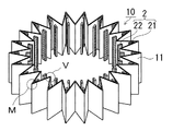
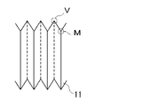
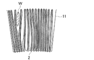
- FIG. 1 A typical structural example of a target pleated filter is schematically shown in FIG.
- the pleated filter 10 in FIG. 1 is formed by forming a pleat shape by repeatedly folding plate-like filter base materials 11 alternately in peaks and troughs, and connecting the both end portions into a cylindrical shape as a whole.
- the upper and lower surfaces of the cylinder are closed with different members and the shape is fixed. Filter from the outside to the inside of the cylindrical filter.
- the V portion of the figure which is a fold projecting to the inside of the cylinder
- the M portion of the diagram which is a fold projecting to the outside of the cylinder
- the valley portion viewed from the inside of the cylinder represents the space on the back side of the M portion between the V portion and the V portion.
- FIG. 1 schematically shows a pleated shape, and an actual crease does not have an ideal acute angle as shown. Also, in order to increase the filtration area, the actual folds are often formed so densely that the surfaces of adjacent substrates touch each other. This will be described later.
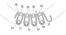
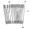
- the pleated filter includes a reinforcing plate 2 that is divided into two as a function.
- a reinforcing plate disposed on the back side of the outer end portion is referred to as a first reinforcing plate 21, and a reinforcing plate disposed in a gap between adjacent inner end portions is referred to as a second reinforcing plate 22.
- the pleated filter has reinforcing plates in all valleys.
- FIG. 2 is a schematic view of a partial cross section of the pleated filter of FIG. 1 as viewed from the upper surface side. In the pleat depth direction of the pleat filter, the first reinforcing plate 21 and the second reinforcing plate 22 are arranged with a separation.
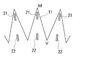
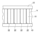
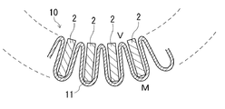
- FIG. 3 is a diagram schematically showing a part of the pleated filter of FIG. 1 as viewed from the inner periphery side of the cylinder.
- FIG. 3 shows the arrangement of the fixing members 12 and 13 in addition to FIG.
- the second reinforcing plate 22 is disposed between the inner end portions (V portion) and is fixed together with the filter base material 11 by the upper fixing member 12 and the lower fixing member 13.
- the fixing members 12 and 13 are disk-shaped or annular members arranged above and below the cylinder, and are members that keep the fixing portions watertight while fixing the shapes of the filter base 11 and the reinforcing plate 2.
- the upper end portion and the lower end portion of the filter base material 11 and the reinforcing plate 2 are fixed with an adhesive and a resin as a sealing material, respectively.
- a porous resin sheet is used for the filter substrate.
- a porous structure such as a stretched porous body, a phase-separated porous body, or a nonwoven fabric made of polyester, nylon, polyethylene, polypropylene, polyurethane, polytetrafluoroethylene (PTFE), polyvinylidene fluoride (PVdF), or the like is used. Is done.
- a nonwoven fabric made of polyester such as polyethylene terephthalate is particularly preferably used.
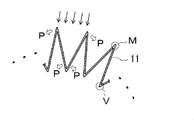
- FIG. 4 is a diagram for explaining the force applied to the filter base 11 in that case.
- the reinforcing plate is not shown.
- five arrows indicate the direction in which the liquid to be processed is supplied from the outer end M side.
- a pressure P is applied to the filter base 11 in the direction in which the pleats are opened. Furthermore, the applied pressure P varies depending on the flow rate and pressure variation of the liquid to be treated, and acts on the filter substrate 11 as vibration or repeated bending depending on the configuration.
- FIG. 5A and FIG. 5B show one form of breakage that occurs in the pleated filter due to the pressure P described above.
- FIG. 5A schematically shows a state before breakage
- FIG. 5B schematically shows a state at breakage.
- the top and bottom of the filter are fixed for shape fixing and sealing. Therefore, when the pressure is repeatedly applied in the direction of opening the outer end portion as shown in FIG. 4, the portion D near the center of the filter is bent in the direction shown in FIG. 5B. As a result, the filter base 11 may be cracked or broken in the vicinity of the filter center portion D, thereby impairing the filtration function.
- the liquid to be filtered is a liquid such as water
- the pressure received by the filter is larger than that of a gas such as air, and the filter is likely to break at the bent portion.
- Opening (bending) the center of the filter in the direction as shown in FIG. 5B is effective in that the liquid to be treated is supplied to the back of the pleat, and the surface of the filter is easily cleaned by the flow.
- the reinforcing plate may be a member having a strength that prevents the filter from being bent and deformed, and it is preferable not to excessively prevent the pleats of the filter from spreading due to the pressure of the water to be treated. That is, as shown in FIG. 5B, it is prevented from bending at an obtuse angle (" ⁇ " shape), but it is curved with a gentle curve and returns to its original shape when released from the pressure of the water to be treated. It is preferable to have
- ⁇ Breaking of the filter base material also occurs at the inner edge of the filter. Although greatly improved by the reinforcing plate, further improvement is required.
- the inventors of the present application pay attention to the fact that the movement of the filter is largely related to the breakage, and as a means to limit the movement, further focus on the fold shape of the filter, leading to the idea of densely constructing the pleats. It was. That is, it is possible to expect an effect of suppressing deformation by configuring the inner circumferential side of the pleat as densely as possible.
- FIG. 6 is an enlarged schematic view of a partial cross section of the pleated filter, which is exaggerated for easy understanding of the actual state.
- the filter base material 11 is not a sharp angle with a bending radius of about zero at both the inner end V and the outer end M, but is a rounded fold. Accordingly, the plane portion as the filter filtration surface is not necessarily a straight line.
- the 1st reinforcement board 21 and the 2nd reinforcement board 22 are arrange
- FIG. 7 is a diagram illustrating a case where one reinforcing plate is arranged at each pleat interval for comparison. Reinforcing plates 2 are arranged in the valleys of the pleats formed by the filter base material 11.
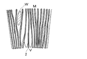
- 8 to 11 are enlarged views of a horizontal section of a cylindrical pleated filter in which the filter base 11 is folded.
- 8 to 11 are simulations of the state in which the water to be treated flows into a part of the pleat while sequentially shifting the position. The water to be treated flows and mixes as a lump W from the external nozzle in the direction of the arrow in the figure, spreads to open the pleats, and enters the pleats.
- FIG. 8 is a diagram for explaining a state in which water to be treated flows into a pleated filter that does not have a reinforcing plate.
- the length of the pleat valley (pleat depth) was 70 mm, and the pleat interval on the inner peripheral side was 2.8 mm.
- the pleats are greatly expanded on the outer peripheral side.
- the folds are likely to be broken by repeating the operations of expanding and returning. Further, the folds of the pleats are widened on the inner peripheral side, and the inner peripheral side is easily damaged by this repetition.
- FIG. 9 shows an example in which one reinforcing plate 2 is provided in each valley of the pleats over the entire depth of the valley.
- the length (pleat depth) of the pleat valleys was 70 mm
- the pleat interval on the inner peripheral side was 4.0 mm
- the thickness of the reinforcing plate was 1.7 mm.
- the pleated filter of FIG. 10 has the same configuration as that of FIG. 9 except that the pleat interval on the inner peripheral side is 3.3 mm and the thickness of the reinforcing plate is 1.7 mm.
- 9 differs from FIG. 9 in that the inner peripheral side is very densely configured. In this way, fluctuations in the inner pleat interval are greatly suppressed. Therefore, damage on the inner peripheral side can be prevented from occurring.
- not only the inner peripheral side can be configured densely, but also all the pleat intervals are narrowed by the reinforcing plate. That is, the space where the water to be treated can exist in the pleat interval is extremely narrow, and the filtration capacity is reduced. Further, it has been found that the cleaning effect on the surface of the filter base material due to the entry and exit of the water to be treated is difficult to obtain, and the filter is easily clogged.
- FIG. 11 shows an example in which the reinforcing plate is divided into a first reinforcing plate 21 and a second reinforcing plate 22 as an embodiment of the present invention.
- the reinforcing plate has a thickness of 1.7 mm and a width of 20 mm.
- the first reinforcing plate 21 on the back side of the outer peripheral portion reinforces the outer peripheral portion side.
- the inner peripheral side is densely configured by the second reinforcing plate 22 on the inner peripheral side, fluctuations in the pleat interval are suppressed, and breakage is suppressed.
- a space without a reinforcing plate can be secured widely in the pleat interval, not only the reduction of the filtration capacity can be suppressed, but also the deterioration of the cleaning effect can be prevented. For this reason, it is possible to continue the filtration operation for a long time without clogging and without causing damage.
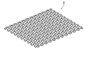
- FIG. 12 shows an example of a resin mesh plate. Even if the reinforcing plate is a simple plate material, the reinforcing effect can be obtained. However, it is preferable to provide a large number of holes penetrating from one side of the plate-like body to the other side. This is because a plate-like body having a large number of holes hardly disturbs the flow of the filtrate. Furthermore, like the mesh plate having the unevenness of FIG.
- the porous plate material in addition to a mesh-like plate material, a punching material in which a large number of holes are formed in the plate material, a plate material having a three-dimensional mesh-like communication hole, or the like can be used.
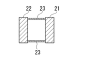
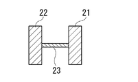
- FIGS. 13 to 15 show an example of a structure in which the first reinforcing plate 21 and the second reinforcing plate 22 are connected by a connecting portion 23, and schematically show front views of the reinforcing plate in plan view.
- the shape and arrangement of the connecting portion are not limited, but the reinforcing plate preferably has a structure that secures a space and a space between the first reinforcing plate and the second reinforcing plate.
- FIGS. 13 and 14 are configuration examples in which both reinforcing plates are connected by a rod-like connecting member.
- FIG. 13 shows a connecting portion 23 on each of the upper and lower ends of the first reinforcing plate 21 and the second reinforcing plate 22. It is an example provided with a total of two.
- FIG. 13 shows a connecting portion 23 on each of the upper and lower ends of the first reinforcing plate 21 and the second reinforcing plate 22. It is an example provided with a total of two.
- FIG. 14 shows an example in which one connecting portion 23 is arranged near the center of the reinforcing plate.
- the number and arrangement of the connecting portions 23 are not limited as long as they have a function of fixing the arrangement of the two reinforcing plates and have a sufficient space between the two reinforcing plates.
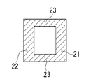
- FIG. 15 is an example of a rectangular frame-like body as an example in which a reinforcing plate having a connecting portion can be simply configured.
- the first reinforcing plate 21, the second reinforcing plate 22, and the connecting portion 23 are integrally formed by removing the center of one plate-like material into a rectangular shape or by using a frame-shaped forming frame. Can do.
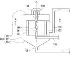
- FIGS. 16A and 16B are diagrams showing an example of a ballast water treatment apparatus for ships as an embodiment of the present invention.
- 16A is a diagram schematically showing a configuration of a vertical section including an axis
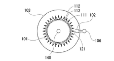
- FIG. 16B is a diagram schematically showing a configuration of a horizontal AA section in FIG. 16A.
- the cylindrical pleated filter 101 is disposed so as to surround an axis serving as a rotation center, and is attached so as to be rotatable around a central pipe 140 (pipe does not rotate) disposed at the center.
- the upper and lower surfaces of the pleated filter are closed watertight.
- the rotatable mounting structure also needs to be a watertight structure, but a known structure is used without any particular limitation.
- a case 103 is provided so as to cover the entire filter.
- the case 103 includes an outer cylinder part 131, a lid part 132, and a bottom part 133, and the bottom part 133 is provided with a discharge channel 108.
- a treated water channel 106 and a treated water nozzle 102 are provided for introducing seawater as treated water into the case 103.
- the treated water nozzle 102 is extended from the treated water flow path 106 so that the nozzle port 121 is provided in the outer cylinder part 131 of the case 103 so that the treated water flows out toward the outer peripheral surface of the pleated filter. It is configured.
- a motor 190 is provided on the central axis of the pleat filter for rotating the pleat filter. The motor 190 is covered and accommodated by a motor cover 191 and is driven by electric power from a drive control unit (not shown).
- the treated water ejected from the treated water nozzle hits the pleated outer peripheral surface of the pleated filter, and the cleaning effect of the pleated filter is obtained by the pressure.
- the untreated water to be treated and the suspended matter settled in the case are sequentially discharged from the discharge channel at the bottom of the case.
- the characteristic of this apparatus is that the filtration proceeds while the turbid component and the remaining water to be treated are continuously discharged, and 10 to 20 tons / hour or even 100 tons / hour required for ballast water. It is effective to secure a processing amount exceeding.
- a valve or the like is not shown in the discharge flow path, but equipment necessary for maintenance and flow rate adjustment is provided.
- the filtered water filtered by the pleated filter 101 is guided to the filtered water flow path 107 through the water intake hole 141 provided in the central pipe 140 inside the filter, and flows out of the case.
- the treated water nozzle 102 may have a rectangular nozzle opening 121.
- vibration in the direction in which the fold of the pleated filter opens and closes is generated, so that holes such as tears are easily opened.
- the pleated filter 101 includes a filter base 111, a first reinforcing plate 112, and a second reinforcing plate 113.
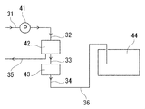
- FIG. 17 is an explanatory view schematically showing the overall configuration of a marine ballast water treatment system using the above-described ballast water treatment device as a filtration device.
- water to be treated which is seawater taken from the ocean, is sent by a pump 41 through a pipe 31 and supplied to a filtration device 42 that is a filtering means through a pipe 32.
- the filtered water filtered in the filtering device 42 is sent to a killing device 43 (not essential) such as an ultraviolet irradiation device or an electrolysis device via a pipe 33.
- the discharged water that has not been filtered in the filtering device 42 is led out of the device through the pipe 35.
- the seawater subjected to the killing process is sent to the tank 44 through the pipe 34 and the pipe 36.
- Example 1 In order to confirm the effect of the reinforcing plate, seawater was filtered using the ballast water treatment apparatus shown in FIGS. 16A and 16B.
- the size of the device is a device that performs processing at 100 ton / hour.
- the outer diameter of the pleat filter is 700 mm, the effective length in the axial direction is 200 mm, the pleat depth is 70 mm, and the number of pleats is 460 folds.
- the materials used are as follows.
- Filter base material Non-woven fabric made of polyethylene terephthalate (trade name: AXTER G2260-1S BK0 manufactured by Toray)
- First reinforcing plate and second reinforcing plate Effective length 200mm x width 10mm
- Polypropylene mesh board (trade name: Takiron Tricarnet SN-598) Mesh pitch 4.8mm x 4.8mm Nominal thickness 1.5mm (warp 1.5mm, weft 1.2mm) The distance between the first reinforcing plate and the second reinforcing plate: 50 mm
- Example 2 The experiment was performed under the same ballast water treatment apparatus and conditions as in Experimental Example 1 except that one reinforcing plate was used between the pleats as the reinforcing plate.
- the reinforcing plate is a single reinforcing plate having a size in which the first reinforcing plate and the second reinforcing plate are continuously connected, and has an effective length of 200 mm and a width of 70 mm.
- the material of the reinforcing plate other than the size is the same as in Experimental Example 1.
- the occurrence of clogging of the pleated filter was confirmed in 20 hours.
- the pleated filter was not damaged after 70 hours.
- the pleated filter of the present invention is superior in durability without causing degradation in performance due to breakage, and therefore, when using brackish water and seawater such as seawater desalination and ballast water, or in water treatment such as sewage, domestic wastewater, and industrial wastewater, It can be suitably used for pre-filtration treatment for removing foreign matters, dust, and microorganisms. In addition, because it is excellent in water treatment and concentration treatment with high turbidity and high SS, it can be applied in the field of valuable resources recovery such as the food field.
Landscapes
- Chemical & Material Sciences (AREA)
- Engineering & Computer Science (AREA)
- Chemical Kinetics & Catalysis (AREA)
- Environmental & Geological Engineering (AREA)
- Organic Chemistry (AREA)
- Water Supply & Treatment (AREA)
- Hydrology & Water Resources (AREA)
- Life Sciences & Earth Sciences (AREA)
- Health & Medical Sciences (AREA)
- Toxicology (AREA)
- Ocean & Marine Engineering (AREA)
- Mechanical Engineering (AREA)
- Combustion & Propulsion (AREA)
- Public Health (AREA)
- General Health & Medical Sciences (AREA)
- Electrochemistry (AREA)
- General Chemical & Material Sciences (AREA)
- Physical Water Treatments (AREA)
- Filtration Of Liquid (AREA)
- Filtering Materials (AREA)
- Water Treatment By Electricity Or Magnetism (AREA)
- Separation Using Semi-Permeable Membranes (AREA)
Priority Applications (4)
| Application Number | Priority Date | Filing Date | Title |
|---|---|---|---|
| US15/034,959 US20160271532A1 (en) | 2013-12-09 | 2014-11-27 | Pleated filter, ballast water treatment apparatus, and ballast water treatment method using the same |
| EP14869486.2A EP3150267A1 (en) | 2013-12-09 | 2014-11-27 | Pleated filter, and ballast water treatment device and ballast water treatment method each using same |
| CN201480066905.7A CN105813707A (zh) | 2013-12-09 | 2014-11-27 | 褶皱式过滤器以及均使用褶皱式过滤器的压载水处理设备和压载水处理方法 |
| KR1020167012201A KR20160096229A (ko) | 2013-12-09 | 2014-11-27 | 플리츠 필터, 그것을 이용한 밸러스트수 처리 장치 및 밸러스트수의 처리 방법 |
Applications Claiming Priority (2)
| Application Number | Priority Date | Filing Date | Title |
|---|---|---|---|
| JP2013254004A JP5811162B2 (ja) | 2013-12-09 | 2013-12-09 | プリーツフィルター、それを用いたバラスト水処理装置およびバラスト水の処理方法 |
| JP2013-254004 | 2013-12-09 |
Publications (1)
| Publication Number | Publication Date |
|---|---|
| WO2015087701A1 true WO2015087701A1 (ja) | 2015-06-18 |
Family
ID=53371013
Family Applications (1)
| Application Number | Title | Priority Date | Filing Date |
|---|---|---|---|
| PCT/JP2014/081301 Ceased WO2015087701A1 (ja) | 2013-12-09 | 2014-11-27 | プリーツフィルター、それを用いたバラスト水処理装置およびバラスト水の処理方法 |
Country Status (6)
| Country | Link |
|---|---|
| US (1) | US20160271532A1 (enExample) |
| EP (1) | EP3150267A1 (enExample) |
| JP (1) | JP5811162B2 (enExample) |
| KR (1) | KR20160096229A (enExample) |
| CN (1) | CN105813707A (enExample) |
| WO (1) | WO2015087701A1 (enExample) |
Families Citing this family (6)
| Publication number | Priority date | Publication date | Assignee | Title |
|---|---|---|---|---|
| JP2016052644A (ja) * | 2014-09-04 | 2016-04-14 | 住友電気工業株式会社 | プリーツフィルター、プリーツフィルターカートリッジ、それを用いたバラスト水処理装置およびバラスト水の処理方法 |
| US11752470B2 (en) | 2016-08-29 | 2023-09-12 | Emd Millipore Corporation | Fixed rigid wall device for compressed pleat configuration filters |
| JP7370695B2 (ja) * | 2018-10-17 | 2023-10-30 | 日本無機株式会社 | フィルタパック、及びエアフィルタ |
| EP4342568B1 (en) * | 2019-05-29 | 2025-04-16 | Donaldson Company, Inc. | Curved core for variable pleat filter |
| CN115069020A (zh) * | 2022-08-05 | 2022-09-20 | 俞信林 | 一种水过滤器 |
| CN115608016A (zh) * | 2022-10-31 | 2023-01-17 | 广东中康织绣科技有限公司 | 含布纤废水预处理装置及处理设备 |
Citations (10)
| Publication number | Priority date | Publication date | Assignee | Title |
|---|---|---|---|---|
| US3486626A (en) * | 1968-02-01 | 1969-12-30 | Sam Close | Replaceable medium,extended area filter unit |
| JPS54123783A (en) * | 1978-03-17 | 1979-09-26 | Hiroshige Akiba | Cartridge system filter unit |
| JPS56158116A (en) * | 1980-05-08 | 1981-12-05 | Tatsuo Kimura | Clarifying filter |
| US4324571A (en) * | 1979-09-26 | 1982-04-13 | Johnson Jr Allen S | Bag-type filter apparatus with air diffuser having extended bag support |
| JPH01203017A (ja) * | 1988-02-10 | 1989-08-15 | Sagami Shokai:Kk | 集塵装置 |
| JP3079032U (ja) * | 2001-01-19 | 2001-08-03 | 大阪熱管理工業株式会社 | ハニカム状のバグフィルター |
| JP2008093783A (ja) | 2006-10-12 | 2008-04-24 | Horyo Corp | フィルタ装置 |
| JP2011189237A (ja) * | 2010-03-12 | 2011-09-29 | Sumitomo Electric Ind Ltd | バラスト水の処理装置およびバラスト水の処理方法 |
| JP4835785B2 (ja) | 2010-02-25 | 2011-12-14 | 住友電気工業株式会社 | 船舶用バラスト水の処理装置 |
| JP2012245428A (ja) * | 2011-05-25 | 2012-12-13 | Sumitomo Electric Ind Ltd | プリーツフィルター、それを用いたバラスト水処理装置、およびプリーツフィルターの製造方法 |
-
2013
- 2013-12-09 JP JP2013254004A patent/JP5811162B2/ja not_active Expired - Fee Related
-
2014
- 2014-11-27 WO PCT/JP2014/081301 patent/WO2015087701A1/ja not_active Ceased
- 2014-11-27 EP EP14869486.2A patent/EP3150267A1/en not_active Withdrawn
- 2014-11-27 KR KR1020167012201A patent/KR20160096229A/ko not_active Withdrawn
- 2014-11-27 US US15/034,959 patent/US20160271532A1/en not_active Abandoned
- 2014-11-27 CN CN201480066905.7A patent/CN105813707A/zh active Pending
Patent Citations (10)
| Publication number | Priority date | Publication date | Assignee | Title |
|---|---|---|---|---|
| US3486626A (en) * | 1968-02-01 | 1969-12-30 | Sam Close | Replaceable medium,extended area filter unit |
| JPS54123783A (en) * | 1978-03-17 | 1979-09-26 | Hiroshige Akiba | Cartridge system filter unit |
| US4324571A (en) * | 1979-09-26 | 1982-04-13 | Johnson Jr Allen S | Bag-type filter apparatus with air diffuser having extended bag support |
| JPS56158116A (en) * | 1980-05-08 | 1981-12-05 | Tatsuo Kimura | Clarifying filter |
| JPH01203017A (ja) * | 1988-02-10 | 1989-08-15 | Sagami Shokai:Kk | 集塵装置 |
| JP3079032U (ja) * | 2001-01-19 | 2001-08-03 | 大阪熱管理工業株式会社 | ハニカム状のバグフィルター |
| JP2008093783A (ja) | 2006-10-12 | 2008-04-24 | Horyo Corp | フィルタ装置 |
| JP4835785B2 (ja) | 2010-02-25 | 2011-12-14 | 住友電気工業株式会社 | 船舶用バラスト水の処理装置 |
| JP2011189237A (ja) * | 2010-03-12 | 2011-09-29 | Sumitomo Electric Ind Ltd | バラスト水の処理装置およびバラスト水の処理方法 |
| JP2012245428A (ja) * | 2011-05-25 | 2012-12-13 | Sumitomo Electric Ind Ltd | プリーツフィルター、それを用いたバラスト水処理装置、およびプリーツフィルターの製造方法 |
Also Published As
| Publication number | Publication date |
|---|---|
| US20160271532A1 (en) | 2016-09-22 |
| CN105813707A (zh) | 2016-07-27 |
| KR20160096229A (ko) | 2016-08-12 |
| EP3150267A1 (en) | 2017-04-05 |
| JP2015112505A (ja) | 2015-06-22 |
| JP5811162B2 (ja) | 2015-11-11 |
Similar Documents
| Publication | Publication Date | Title |
|---|---|---|
| CN102015054B (zh) | 盘式过滤器的耐受废物的过滤器支撑件 | |
| EP2612696B1 (en) | Method of filtering | |
| JP5811162B2 (ja) | プリーツフィルター、それを用いたバラスト水処理装置およびバラスト水の処理方法 | |
| CN105246570B (zh) | 过滤装置、压载水处理方法以及使用过滤装置的压载水处理设备 | |
| WO2014103854A1 (ja) | バラスト水処理装置およびバラスト水処理装置の逆洗浄方法 | |
| JP6019909B2 (ja) | 液体濾過装置およびそれを用いたバラスト水処理装置 | |
| JP2016002520A (ja) | プリーツフィルター、プリーツフィルターカートリッジ、それを用いたバラスト水処理装置およびバラスト水の処理方法 | |
| KR20140138008A (ko) | 선박용 밸러스트수의 처리 시스템 | |
| WO2015111496A1 (ja) | プリーツフィルター、それを用いたバラスト水処理装置およびバラスト水の処理方法 | |
| JP2013180666A (ja) | 船舶用バラスト水の処理システムおよび船舶用バラスト水の処理方法 | |
| WO2016035688A1 (ja) | プリーツフィルター、プリーツフィルターカートリッジ、それを用いたバラスト水処理装置およびバラスト水の処理方法 | |
| JP5716931B2 (ja) | プリーツフィルター、それを用いたバラスト水処理装置およびバラスト水の処理方法 | |
| JP2015009170A (ja) | プリーツフィルター、それを用いたバラスト水処理装置およびバラスト水の処理方法 | |
| WO2012148653A1 (en) | Contaminant removal system utilizing disc filter | |
| WO2015072381A1 (ja) | プリーツフィルター、それを用いたバラスト水処理装置およびバラスト水の処理方法 | |
| KR20170141106A (ko) | 여과 장치, 플리츠 필터 및 밸러스트수의 처리 방법 | |
| KR101206904B1 (ko) | 자동세척기능을 가지는 연속 회전식 여과장치 | |
| JP2016198707A (ja) | バラスト水処理装置およびバラスト水処理装置の洗浄方法 |
Legal Events
| Date | Code | Title | Description |
|---|---|---|---|
| 121 | Ep: the epo has been informed by wipo that ep was designated in this application |
Ref document number: 14869486 Country of ref document: EP Kind code of ref document: A1 |
|
| REEP | Request for entry into the european phase |
Ref document number: 2014869486 Country of ref document: EP |
|
| WWE | Wipo information: entry into national phase |
Ref document number: 2014869486 Country of ref document: EP |
|
| WWE | Wipo information: entry into national phase |
Ref document number: 15034959 Country of ref document: US |
|
| ENP | Entry into the national phase |
Ref document number: 20167012201 Country of ref document: KR Kind code of ref document: A |
|
| NENP | Non-entry into the national phase |
Ref country code: DE |