WO2015087671A1 - 電力貯蔵装置 - Google Patents
電力貯蔵装置 Download PDFInfo
- Publication number
- WO2015087671A1 WO2015087671A1 PCT/JP2014/080596 JP2014080596W WO2015087671A1 WO 2015087671 A1 WO2015087671 A1 WO 2015087671A1 JP 2014080596 W JP2014080596 W JP 2014080596W WO 2015087671 A1 WO2015087671 A1 WO 2015087671A1
- Authority
- WO
- WIPO (PCT)
- Prior art keywords
- air
- storage device
- power storage
- battery
- cooling
- Prior art date
- Legal status (The legal status is an assumption and is not a legal conclusion. Google has not performed a legal analysis and makes no representation as to the accuracy of the status listed.)
- Ceased
Links
Images





Classifications
-
- H—ELECTRICITY
- H01—ELECTRIC ELEMENTS
- H01M—PROCESSES OR MEANS, e.g. BATTERIES, FOR THE DIRECT CONVERSION OF CHEMICAL ENERGY INTO ELECTRICAL ENERGY
- H01M10/00—Secondary cells; Manufacture thereof
- H01M10/60—Heating or cooling; Temperature control
- H01M10/65—Means for temperature control structurally associated with the cells
- H01M10/656—Means for temperature control structurally associated with the cells characterised by the type of heat-exchange fluid
- H01M10/6561—Gases
- H01M10/6563—Gases with forced flow, e.g. by blowers
-
- H—ELECTRICITY
- H01—ELECTRIC ELEMENTS
- H01M—PROCESSES OR MEANS, e.g. BATTERIES, FOR THE DIRECT CONVERSION OF CHEMICAL ENERGY INTO ELECTRICAL ENERGY
- H01M50/00—Constructional details or processes of manufacture of the non-active parts of electrochemical cells other than fuel cells, e.g. hybrid cells
- H01M50/20—Mountings; Secondary casings or frames; Racks, modules or packs; Suspension devices; Shock absorbers; Transport or carrying devices; Holders
- H01M50/204—Racks, modules or packs for multiple batteries or multiple cells
-
- H—ELECTRICITY
- H01—ELECTRIC ELEMENTS
- H01M—PROCESSES OR MEANS, e.g. BATTERIES, FOR THE DIRECT CONVERSION OF CHEMICAL ENERGY INTO ELECTRICAL ENERGY
- H01M10/00—Secondary cells; Manufacture thereof
- H01M10/60—Heating or cooling; Temperature control
- H01M10/61—Types of temperature control
- H01M10/613—Cooling or keeping cold
-
- H—ELECTRICITY
- H01—ELECTRIC ELEMENTS
- H01M—PROCESSES OR MEANS, e.g. BATTERIES, FOR THE DIRECT CONVERSION OF CHEMICAL ENERGY INTO ELECTRICAL ENERGY
- H01M10/00—Secondary cells; Manufacture thereof
- H01M10/60—Heating or cooling; Temperature control
- H01M10/62—Heating or cooling; Temperature control specially adapted for specific applications
- H01M10/627—Stationary installations, e.g. power plant buffering or backup power supplies
-
- H—ELECTRICITY
- H01—ELECTRIC ELEMENTS
- H01M—PROCESSES OR MEANS, e.g. BATTERIES, FOR THE DIRECT CONVERSION OF CHEMICAL ENERGY INTO ELECTRICAL ENERGY
- H01M10/00—Secondary cells; Manufacture thereof
- H01M10/60—Heating or cooling; Temperature control
- H01M10/65—Means for temperature control structurally associated with the cells
- H01M10/655—Solid structures for heat exchange or heat conduction
- H01M10/6556—Solid parts with flow channel passages or pipes for heat exchange
-
- H—ELECTRICITY
- H01—ELECTRIC ELEMENTS
- H01M—PROCESSES OR MEANS, e.g. BATTERIES, FOR THE DIRECT CONVERSION OF CHEMICAL ENERGY INTO ELECTRICAL ENERGY
- H01M10/00—Secondary cells; Manufacture thereof
- H01M10/60—Heating or cooling; Temperature control
- H01M10/65—Means for temperature control structurally associated with the cells
- H01M10/656—Means for temperature control structurally associated with the cells characterised by the type of heat-exchange fluid
- H01M10/6561—Gases
-
- Y—GENERAL TAGGING OF NEW TECHNOLOGICAL DEVELOPMENTS; GENERAL TAGGING OF CROSS-SECTIONAL TECHNOLOGIES SPANNING OVER SEVERAL SECTIONS OF THE IPC; TECHNICAL SUBJECTS COVERED BY FORMER USPC CROSS-REFERENCE ART COLLECTIONS [XRACs] AND DIGESTS
- Y02—TECHNOLOGIES OR APPLICATIONS FOR MITIGATION OR ADAPTATION AGAINST CLIMATE CHANGE
- Y02E—REDUCTION OF GREENHOUSE GAS [GHG] EMISSIONS, RELATED TO ENERGY GENERATION, TRANSMISSION OR DISTRIBUTION
- Y02E60/00—Enabling technologies; Technologies with a potential or indirect contribution to GHG emissions mitigation
- Y02E60/10—Energy storage using batteries
Definitions
- the present invention relates to a power storage device in which a large number of battery packs are accommodated in a storage battery panel.
- a power storage device is provided.
- the power storage device When backing up electric power in a factory or office building, the power storage device is arranged in a power supply room provided in a building such as a factory. If the container equipped with the power storage device is arranged adjacent to the factory building, the power can be backed up at the peak of power use in the production facilities of the factory.
- the container When the power storage device is mounted on the container, the container can be transported by land using a trailer or can be transported by sea using a ship, and power can be backed up against a power load when a power failure occurs.
- a battery unit panel for configuring the power storage device is described in Patent Document 1.
- a plurality of battery unit cases are provided in a casing, and battery units, that is, battery packs are accommodated in the battery unit cases, respectively.
- the front wall of the battery unit case is provided with a case air inlet
- the rear wall of the battery unit case is provided with a case air outlet
- each electric unit case is horizontally oriented from the case air inlet to the case air outlet.
- the cooling air is guided in the direction.
- the casing is provided with a partition plate, and an exhaust chamber is provided on the back side of the partition plate. In order to connect each case exhaust port to the exhaust chamber, an opening is provided in the partition plate, and the cooling air discharged from the case exhaust port is guided to the exhaust chamber through the opening. .
- An object of the present invention is to increase the cooling efficiency of a battery pack, mount a large number of battery packs on a storage battery board, and cool the battery pack efficiently.
- the power storage device of the present invention has a storage battery board having left and right side walls, a back wall, and a top wall, provided with an opening / closing door on the front side, and provided with a plurality of shelves with an interval in the vertical direction inside.
- a vent that forms a cooling flow path from the bottom side to the upper side in the storage battery panel so as to cross the battery cell, and the ceiling wall are provided, and the cooling flow path is directed from the bottom side to the upper side.
- a cooling fan that generates cooling air.
- the storage battery panel is provided with an interval in the vertical direction, and vents are formed in the shelf plates on which the battery packs are arranged, respectively, and the storage battery panel is provided with each vent hole.
- a cooling channel that guides the rising cooling air from the bottom side toward the upper side is formed. Cooling air flowing from the lower side to the upper side of the cooling flow path flows across the battery cells of the battery pack to cool the battery cells. The cooling air flowing in the direction crossing the battery cell is reliably abutted against the outer peripheral surface of the battery cell, and the battery pack can be reliably cooled.
- the battery pack cooling efficiency can be increased by directly exposing the battery cells of the battery pack to the cooling air without providing a battery unit case outside the battery pack. A large number of battery packs can be accommodated. Thereby, a large amount of electric power can be stored without increasing the size of the storage battery panel.
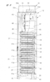
- FIG. 3 is a sectional view taken along line AA in FIG. 2.
- FIG. 3 is a sectional view taken along line BB in FIG. 2.
- FIG. 2 is a sectional view taken along line CC in FIG. 1.
- FIG. 2 is a sectional view taken along line DD in FIG.
- It is sectional drawing which shows the part similar to FIG. 8 in the electric power storage apparatus which is other embodiment.
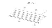
- It is a perspective view of the plane side which shows a shelf board. It is a perspective view of the bottom face side which shows a shelf board.
- the power storage device 10 includes a housing, that is, a storage battery board 11.
- the storage battery board 11 has left and right side walls 12, 13, a back wall 14, and a top wall 15, and an opening / closing door 16 is provided on the front side so as to be opened and closed.
- the storage battery board 11 has side walls 12, 13, a back wall 14, and a top wall 15, which are fixed to pillars arranged at the four corners of the storage battery board 11.
- a plurality of shelf boards 18 are provided in the storage battery panel 11 at intervals in the vertical direction.
- the seven shelf boards 18 are provided in the storage battery board 11 to show in figure, the number of the shelf boards 18 is not restricted to the case where it shows in figure, It can be made into arbitrary numbers.
- a plurality of battery units, that is, battery packs 21 are fixed to each shelf board 18.
- Each battery pack 21 has a plurality of battery cells 22 as shown in FIGS. 4 to 8, and the battery cells 22 are electrically connected in series.
- Each battery cell 22 is constituted by a cylindrical lithium ion secondary battery, and both end portions thereof are abutted against substantially quadrangular resin end plate members 23 and 24.
- the battery pack 21 has the plurality of battery cells 22 and the end plate members 23 and 24, and the front and rear end plate members 23 and 24 are connected by the connecting rod and the frame member.
- the outer peripheral surface is exposed to the outside without being covered by the case member.
- the battery pack 21 is fixed to the shelf plate 18 by end plate members 23 and 24.
- a battery fixing bracket 25 is attached to the shelf plate 18, and the battery pack 21 is attached to the shelf plate 18 by fixing the end plate member 23 with the battery fixing bracket 25.
- one battery pack 21 has six battery cells 22 as shown in the figure, the number of battery cells 22 provided in one battery pack 21 is not limited to six and can be any number. can do. The battery cells 22 do not contact each other, and a gap 26 is provided between the battery cells 22 as shown in FIG.
- One of the front and rear end plate members 23 and 24 constituting the battery pack 21 is a terminal plate, and the end plate members constituting the terminal plate are provided with terminal electrodes, and are adjacent to each other vertically.
- the terminal electrodes 21 are connected by a current-carrying member (not shown). Thereby, the battery pack 21 as a total of 28 secondary batteries is connected in series.
- the shelf board 18 is provided with a plurality of vent holes 27.
- the plurality of vent holes 27 have slit shapes extending in the longitudinal direction of the shelf board 18.
- a plurality of air intake ports 28 are provided at intervals in the longitudinal direction at the front and rear bent portions of the shelf board 18.
- a fan case 31 is provided on the top surface of the top wall 15.
- the fan case 31 has a front case piece 32a, left and right case pieces 32b and 32c, a rear case piece 32d, and an upper case piece 32e. Yes.
- three cooling fans 33 are arranged in the fan case 31, and each cooling fan 33 is provided on the top wall 15 of the storage battery panel 11.
- the cooling fan 33 is driven, the air in the storage battery panel 11 is discharged to the outside, and cooling air flowing through the cooling flow path 29 is generated.
- the cooling air flows in a direction crossing the outer peripheral surface of each battery cell 22 from the bottom side to the top side of the storage battery board 11. That is, the cooling air flows in a direction that crosses the battery cells 22.
- an air inlet 34 is provided in the opening / closing door 16 on the front side of the storage battery panel 11.
- the air inlet 34 is formed by a plurality of slits 35 extending in the vertical direction.
- the air inlet 34 is formed by the slit group.
- the two rows of slit groups 34a and 34b from the bottom are formed on the open / close door 16 corresponding to the lower part of the shelf 18 at the bottom, and the third to fifth rows of slit groups 34c to 34e from the bottom are formed.
- the opening / closing door 16 is formed so as to correspond to a portion below the shelf 18 at the third step from the bottom. Further, a slit group 34f is formed in the open / close door 16 so as to correspond to the lower part of the fourth shelf board 18 from the bottom, and in the lower part of the fifth shelf board 18 from the bottom. Correspondingly, a slit group 34g is formed in the open / close door 16, and a slit group 34h is formed in the open / close door 16 corresponding to a portion below the shelf 18 in the sixth step from the bottom.
- the slit group constituting the air inlet 34 is provided in a portion below the center portion of the open / close door 16 in the vertical direction. External air introduced from the lower two rows of slit groups 34 a and 34 b flows into the cooling channel 29 from the lower side of the bottom shelf 18.
- the external air introduced from the slit groups 34c to 34h is introduced to the front side of the battery pack 21, and the shelf plates 18 which are adjacent to each other vertically from the air intake port 28 formed on the front surface of each shelf plate 18. Flows in between. Therefore, external air is replenished from each air intake port 28 so as to assist the cooling air supplied from the lower side of the bottom shelf 18 to the cooling flow path 29.
- the cooling fan 33 is disposed on the top wall 15 of the storage battery panel 11, and the air introduction port 34 is provided at a portion lower than the substantially central portion in the vertical direction of the opening / closing door 16.
- the sucked external air flows into the cooling flow path 29 from the lower part thereof and rises toward the cooling fan 33. Since the cooling air is heated by the battery cell 22, the cooling air rises due to the temperature rise, and the battery cell 22 can be reliably cooled.
- three cooling fans 33 are provided, but the number is not limited to three and may be any number according to heat generation.
- a mounting position of a cooling fan it is good also as a form accommodated in a storage battery panel.
- the front case piece 32a of the fan case 31 is provided with an air discharge port 36, and the air discharge port 36 is formed by a plurality of slits 37 extending in the vertical direction.
- the air discharge port 36 is formed by the slit group.
- a plurality of air guide plates 41a to 41e are provided at intervals in the vertical direction. Each of the air guide plates 41a to 41e suppresses the outside air flowing into the storage battery panel 11 from the air introduction port 34 from flowing upward through the gap between the open / close door 16 and the front surface of the battery pack 21, External air is guided toward the battery pack 21.
- the air guide plates 41a to 41e are provided at predetermined intervals in the vertical direction in the left and right doors 16 respectively.
- the right air guide plates 41a to 41e are provided. Is shown by a solid line, and the left air guide plates 41a to 41e are shown by two-dot chain lines.
- the opening / closing door 16 is removed, and the positional relationship of the air guide plate attached to the opening / closing door 16 with respect to the shelf board 18 is indicated by a solid line and a two-dot chain line.
- the air guide plates 41a to 41e shown in FIG. 7 and FIG. 8 protrude in the horizontal direction toward the battery pack 21, and the external air guided toward the battery pack 21 by the air guide plate is a shelf plate. 18 is introduced into the cooling flow path 29 from the air intake port 28 formed on the front surface of the air 18.
- Each wind guide plate is attached to the inner surface of the door 16 in the case of illustration, but the wind guide plate may be attached to the left and right side walls 12 and 13 on the front side of the storage battery panel 11.
- the shelf plate 18 when the air guide plate is fixed to the shelf plate 18, the shelf plate 18 can also be fixed to the side wall via the air guide plate. The mounting strength of 18 can be increased.
- the lowermost air guide plate 41a shown in FIG. 7 guides the external air introduced from the lower two rows of slit groups 34a and 34b to the lower side of the lowermost shelf 18.
- the second baffle plate 41b from the bottom guides the external air introduced from the third to fifth rows of slit groups 34c to 34e from the bottom toward the battery pack 21 facing the slit group.
- the other air guide plates 41c to 41e guide the external air introduced from the slit groups 34f to 34h toward the battery pack 21 facing the slit group, respectively.
- a partition plate 42 is provided on the back side of each shelf plate 18 to partition the gap between the shelf plate 18 and the back wall 14.
- the cooling air is prevented from flowing from the gap between the back wall 18 and the back wall 14 toward the upper side of the storage battery panel 11. Thereby, the cooling air is reliably guided toward the battery cell 22.
- an auxiliary cooling fan 43 is disposed at the bottom of the storage battery panel 11.
- the auxiliary cooling fan 43 sucks the external air introduced from the air introduction port 34 into the storage battery panel 11 and introduces it into the cooling flow path 29 as an auxiliary.
- the bottom of the storage battery panel 11 is moved toward the back side of the storage battery panel 11.
- a bottom air guide plate 44 is provided. Thereby, the external air sucked by the auxiliary cooling fan 43 is supplied to the cooling flow path 29 without going around to the back side of the storage battery board 11. As shown in FIG.
- auxiliary cooling fans 43 are provided at the bottom of the storage battery board 11, but the number of auxiliary cooling fans 43 can be any number. If the cooling fan 33 can generate a cooling air flow with a sufficient flow rate in the cooling flow path 29, the auxiliary cooling fan 43 can be omitted. Furthermore, as shown in the drawing, the auxiliary cooling fan 43 may be disposed above the bottom shelf 18 without being disposed below the bottom shelf 18 as shown in the drawing. .
- a base plate 45 is provided on the upper side of the uppermost battery pack 21.
- the base plate 45 is provided with a vent as in the case of the shelf plate 18, and the cooling air that has passed through the vent is cooled by a cooling fan. It flows toward 33 fan inlets.
- a support plate 46 is provided near the front side of the storage battery board 11 on the base plate 45, and a control unit 47 is attached to the back side of the support plate 46. The control unit 47 is arranged so as not to disturb the cooling air flow path of the battery pack.
- An operation member such as a breaker 48 is provided on the front surface of the support plate 46.
- a partition plate 49 is provided in front of the support plate 46 so as to cover the support plate 46, and the partition plate 49 suppresses air from flowing to the inner surface of the open / close door 16 in the upper part of the storage battery panel 11. .
- the partition plate 49 is provided with an opening window 51 of the breaker.
- a plurality of battery packs 21 are attached to the shelf board 18 arranged in the storage battery panel 11 at intervals in the vertical direction.
- the battery pack 21 includes a plurality of battery cells 22 made of lithium ion secondary electricity or the like, and the battery cells 22 are positioned on the shelf board 18 in the horizontal direction.
- Each shelf plate 18 is provided with a vent 27, and a cooling channel 29 is formed in the storage battery panel 11 from the lower side to the upper side by the vent 27.
- cooling air directed upward is generated by a cooling fan 33 provided in the storage battery panel 11, and the cooling air flows around the battery cell 22 in a direction crossing the battery cell 22.
- FIG. 9 is a cross-sectional view showing a storage battery board 11 according to another embodiment.
- symbol is attached
- the air guide plates 41 a to 41 e provided inside the opening / closing door 16 are inclined downward from the opening / closing door side toward the inside of the storage battery panel 11. Accordingly, the external air introduced into the storage battery panel 11 from the air introduction port 34 is introduced downward toward the cooling flow path 29 by the air guide plates 41a to 41e, and then flows through the cooling flow path 29 upward. Become a wind.
- the amount of external air supplied to the cooling flow path 29 can be increased, and the cooling effect can be enhanced.
- This power storage device is applied to supply power in factories and office buildings.
Landscapes
- Chemical & Material Sciences (AREA)
- Chemical Kinetics & Catalysis (AREA)
- Electrochemistry (AREA)
- General Chemical & Material Sciences (AREA)
- Engineering & Computer Science (AREA)
- Manufacturing & Machinery (AREA)
- Secondary Cells (AREA)
- Battery Mounting, Suspending (AREA)
Abstract
電池パックの冷却効率を高めて蓄電池盤に多数の電池パックを搭載し、効率良く電池パックを冷却する。電力貯蔵装置10は、それぞれ複数の電池パック21が配置される複数の棚板18が設けられた蓄電池盤11を有している。電池パック21は、水平方向に延びる複数の電池セル22と端板部材23,24とを有している。それぞれの棚板18には、電池セル22を横切るように蓄電池盤11の内部に底部側から上部側に向かう冷却流路29を形成する通気口27が設けられている。蓄電池盤11の天壁15には、冷却流路29に冷却風を生成する冷却ファン33が設けられている。
Description
本発明は、多数の電池パックを蓄電池盤に収容するようにした電力貯蔵装置に関する。
工場やオフィスビルには、使用電力がピークとなるときに電力をバックアップし、使用電力が少ないときにはリチウムイオン二次電池やリチウムイオンキャパシタ等からなる電池セルを備えた電池パックに充電するようにした電力貯蔵装置が設けられている。工場やオフィスビルにおける電力をバックアップする場合には、電力貯蔵装置は工場等の建屋に設けられた電源室内に配置される。電力貯蔵装置が搭載されたコンテナを工場の建屋に隣接して配置しておくと、同様に工場の生産設備における電力使用のピーク時に電力をバックアップすることができる。
電力貯蔵装置をコンテナに搭載するようにすると、トレーラによりコンテナを陸上輸送したり、船舶により海上輸送したりすることができ、停電発生時に電力負荷に対して電力をバックアップすることができる。
電力貯蔵装置を構成するための電池ユニット盤が、特許文献1に記載されている。この電池ユニット盤においては、筐体内に複数の電池ユニットケースを設け、電池ユニットつまり電池パックをそれぞれ電池ユニットケース内に収容するようにしている。電池ユニットケースの前面壁にはケース吸気口が設けられ、電池ユニットケースの後面壁にはケース排気口が設けられており、それぞれの電気ユニットケース内にケース吸引口からケース排気口に向けて水平方向に冷却空気を案内するようにしている。筐体には仕切り板が設けられており、仕切り板の背面側には排気室が設けられている。それぞれのケース排気口を排気室に連通させるために、仕切り板には開口部が設けられており、ケース排気口から排出された冷却風は開口部を介して排気室に案内するようにしている。
上記特許文献1に記載されるように、電池ユニットを電池ユニットケース内に収容するとともに、電池ユニットと電池ユニットケースとの間に冷却風が流れる通風流路を形成するようにすると、電池ユニットケースを含めた電池ユニットのサイズが大型化され、排気室を設置しているので、1台の筐体に収容することができる電池ユニットつまり電池パックの数を増加させることができなくなる。
一方、冷却風を電池ユニットの前面側から後面側に向けて水平方向に流すようにすると、電池パックの後部にまで冷却風を供給するには、冷却風の風量や風速を高めるために、大型の冷却ファンを筐体に設置する必要があり、設置環境に制限があると筐体が設置できないこともある。また、特許文献1では電池ユニット単位でファンを取り付ける例では上記問題点は解決できると考えられるが、消耗品であるファンの台数が電池ユニット単位で必要となるため、大規模蓄電システムなどでは保守や品質の維持が困難となる。
本発明の目的は、電池パックの冷却効率を高めて蓄電池盤に多数の電池パックを搭載し、効率良く電池パックを冷却することにある。
本発明の電力貯蔵装置は、左右の側壁、背面壁および天壁を有し、正面側に開閉扉が設けられ、内部に上下方向に間隔を隔てて複数の棚板が設けられた蓄電池盤と、水平方向に延びる複数の電池セル、および前記電池セルの両端部に固定される端板部材を有し、前記棚板に固定される複数の電池パックと、それぞれの前記棚板に設けられ、前記電池セルを横切るように前記蓄電池盤内に底部側から上部側に向かう冷却流路を形成する通気口と、前記天壁に設けられ、前記冷却流路に前記底部側から前記上部側に向かう冷却風を生成する冷却ファンと、を有する。
本発明の電力貯蔵装置においては、蓄電池盤に上下方向に間隔を隔てて設けられ、それぞれ電池パックが配置される棚板に通気口が形成されており、それぞれの通気口により蓄電池盤内には底部側から上部側に向けて上昇冷却風を案内する冷却流路が形成される。冷却流路を下側から上部に流れる冷却風は、電池パックの電池セルを横切るように流れて電池セルを冷却する。電池セルを横切る方向に流れる冷却風は、電池セルの外周面に確実に突き当てられることになり、電池パックを確実に冷却することができる。このように、電池パックの外側に電池ユニットケースを設けることなく、電池パックの電池セルを直接冷却風に曝すことにより電池パックの冷却効率を高めることができるので、限られた蓄電池盤のスペース内に多数の電池パックを収容することができる。これにより、蓄電池盤を大型化することなく、多量の電力を蓄電することができる。
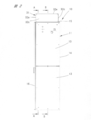
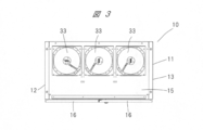
以下、本発明の実施の形態を図面に基づいて詳細に説明する。電力貯蔵装置10は、図1~図3に示されるように、筐体つまり蓄電池盤11を有している。蓄電池盤11は左右の側壁12,13と、背面壁14と、天壁15とを有し、正面側には開閉扉16が開閉自在に設けられている。蓄電池盤11は、側壁12,13、背面壁14および天壁15を有し、これらは蓄電池盤11の四隅に配置された支柱に固定されている。
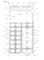
図4~図8に示されるように、蓄電池盤11の内部には、上下方向に間隔を隔てて複数の棚板18が設けられている。図示する蓄電池盤11内には、7つの棚板18が設けられているが、棚板18の数は図示する場合に限られることなく、任意の数とすることができる。
それぞれの棚板18には、複数の電池ユニットつまり電池パック21が固定される。それぞれの電池パック21は、図4~図8に示されるように、複数の電池セル22を有し、電池セル22は電気的に直列に接続されている。それぞれの電池セル22は円筒形状のリチウムイオン二次電池により構成され、両端部はほぼ四辺形の樹脂製の端板部材23,24に突き当てられている。このように、電池パック21は、複数の電池セル22と端板部材23,24とを有し、前後の端板部材23,24は連結ロッドや枠部材により連結されており、電池セル22の外周面は、ケース部材に覆われることなく、外部に露出されている。電池パック21は端板部材23,24により棚板18に固定される。棚板18には電池固定金具25が取り付けられるようになっており、端板部材23を電池固定金具25により固定することにより、電池パック21は棚板18に取り付けられる。1つの電池パック21は、図示するように6つの電池セル22を有しているが、1つの電池パック21に設けられる電池セル22の数は、6つに限られることなく、任意の数とすることができる。それぞれの電池セル22は相互に接触することなく、電池セル22の相互間には、図6に示すように、隙間26が設けられている。
電池パック21を構成する前後の端板部材23,24のうちの一方は、端子板となっており、端子板を構成する端板部材には、端子電極が設けられ、上下に隣り合う電池パック21の端子電極間は図示しない通電部材により接続される。これにより、合計28個の二次電池としての電池パック21は直列に接続される。
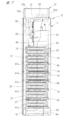
図10および図11に示されるように、棚板18には複数の通気口27が設けられている。複数の通気口27は、図示するように、それぞれ棚板18の長手方向に延びるスリット状となっている。さらに、棚板18の前後の折り曲げ部には、複数の空気取り込み口28が長手方向に間隔を隔てて設けられている。このように、それぞれ電池パック21が取り付けられる棚板18に通気口27を設けると、図7に破線の矢印で示されるように、最下段の棚板18から最上段の棚板18との間には、蓄電池盤11の底部側から上部側に向かう冷却流路29が棚板18の通気口27により形成される。この冷却流路29は、電池セル22が棚板18の上に水平方向に配置されているので、電池セル22を横切る方向となっている。
天壁15の上面にはファンケース31が設けられており、ファンケース31は、正面側ケース片32a、左右側ケース片32b,32c、背面側ケース片32d、および上側ケース片32eを有している。ファンケース31内には、図3に示されるように、3台の冷却ファン33が配置されており、それぞれの冷却ファン33は蓄電池盤11の天壁15に設けられている。冷却ファン33を駆動すると、蓄電池盤11内の空気を外部に排出し、冷却流路29を流れる冷却風が生成される。この冷却風は、蓄電池盤11の底部側から上部側に向けてそれぞれの電池セル22の外周面を横切る方向に流れる。つまり、冷却風は、電池セル22をクロスする方向の流れとなる。
外部空気を蓄電池盤11内に導入するために、蓄電池盤11の正面側の開閉扉16には、空気導入口34が設けられている。空気導入口34は、図1に示されるように、上下方向に延びる複数のスリット35により形成されており、複数のスリット35を左右方向つまり水平方向に列となって形成することにより、全てのスリット群により空気導入口34が形成される。下から2列のスリット群34a,34bは、最下段の棚板18より下側の部分に対応して開閉扉16に形成され、下から3列目~5列目のスリット群34c~34eは、下から3段目の棚板18よりも下側の部分に対応して開閉扉16に形成されている。さらに、下から4段目の棚板18よりも下側の部分に対応されて開閉扉16には、スリット群34fが形成され、下から5段目の棚板18よりも下側の部分に対応されて開閉扉16には、スリット群34gが形成され、下から6段目の棚板18よりも下側の部分に対応されて開閉扉16には、スリット群34hが形成されている。空気導入口34をそれぞれスリット群により形成することによって、水平方向にほぼ均一に分散された状態となって蓄電池盤11内に外部空気が導入される。
図1に示されるように、空気導入口34を構成するスリット群は開閉扉16の上下方向ほぼ中央部よりも下側の部分に設けられている。下側2列のスリット群34a,34bから導入された外部空気は、最下段の棚板18の下側から冷却流路29に流入する。これに対し、スリット群34c~34hから導入された外部空気は、電池パック21の正面側に導入され、それぞれの棚板18の前面に形成された空気取り込み口28から上下に隣り合う棚板18の間に流入する。したがって、それぞれの空気取り込み口28からは、最下段の棚板18の下側から冷却流路29に供給された冷却風を、補助するように外部空気が冷却風に補充される。
このように、冷却ファン33を蓄電池盤11の天壁15の上に配置し、空気導入口34を開閉扉16の上下方向ほぼ中央部よりも下側の部分に設けたので、冷却ファン33により吸引される外部空気は冷却流路29にその下側の部分から流入し、冷却ファン33に向けて上昇する。この冷却風は、電池セル22により加熱されることからも温度上昇により上昇し、電池セル22を確実に冷却することができる。冷却ファン33は図示する場合には3台設けられているが、その数は3台に限られることなく、発熱に応じた任意の台数とすることができる。また、冷却ファンの取付位置としては、蓄電池盤内に収納する形態としても良い。
ファンケース31の正面側ケース片32aには、図1に示されるように、空気排出口36が設けられており、空気排出口36は、上下方向に延びる複数のスリット37により形成されている。複数のスリット37を左右方向つまり水平方向に列となって形成することにより、スリット群により空気排出口36が形成される。これにより、冷却ファン33により冷却流路29を流れて電池セル22を冷却した後の空気は、正面側ケース片32aから全体的に均一に分散された状態となって蓄電池盤11の前方に排出される。空気排出口36はファンの排気の向きにあわせて形成される。
開閉扉16の内側には、空気導入口34から蓄電池盤11内に流入した外部空気を上下に隣り合う棚板18の間に向けて案内するために、図7および図8に示されるように、複数の導風板41a~41eが上下方向に間隔を隔てて設けられている。それぞれの導風板41a~41eは、空気導入口34から蓄電池盤11内に流入した外部空気が開閉扉16と電池パック21の前面との間の隙間を通って上方に流れることを抑制し、外部空気を電池パック21に向けて案内する。
導風板41a~41eは、図4に示されるように、左右の開閉扉16のそれぞれに上下方向に所定の間隔を隔てて設けられており、図4においては右側の導風板41a~41eが実線で示され、左側の導風板41a~41eは二点鎖線により示されている。図4においては、開閉扉16を取り除き、開閉扉16に取り付けられた導風板の棚板18に対する位置関係が実線と二点鎖線とにより示されている。
図7および図8に示した導風板41a~41eは、水平方向となって電池パック21に向けて突出しており、導風板により電池パック21に向けて案内された外部空気は、棚板18の前面に形成された空気取り込み口28から冷却流路29に導入される。
それぞれの導風板は、図示する場合には開閉扉16の内面に取り付けられているが、蓄電池盤11の正面側の左右の側壁12,13に導風板を取り付けるようにしても良い。このように、導風板を側壁に取り付けるようにした形態においては、導風板を棚板18に固定すると、導風板を介して棚板18を側壁にも固定することがで、棚板18の取付強度を高めることができる。
図7に示される最下段の導風板41aは、下側2列のスリット群34a,34bから導入された外部空気を最下段の棚板18の下側に案内する。下から2段目の導風板41bは、下から3列目~5列目のスリット群34c~34eから導入された外部空気を、スリット群に対向する電池パック21に向けて案内する。同様に、他の導風板41c~41eは、それぞれスリット群34f~34hから導入された外部空気を、スリット群に対向する電池パック21に向けて案内する。
それぞれの棚板18の背面側には、図7および図8に示されるように、棚板18と背面壁14との間の隙間を仕切るために、仕切り板42が設けられており、棚板18と背面壁14との間の隙間から蓄電池盤11の上方に向け冷却風が流れることが抑制されている。これにより、冷却風は確実に電池セル22に向けて案内される。
蓄電池盤11の底部には、図4および図8に示されるように、補助冷却ファン43が配置されている。この補助冷却ファン43は空気導入口34から導入された外部空気を蓄電池盤11内に吸引して冷却流路29に補助的に導入する。補助冷却ファン43に吸引された空気を、最下段の電池セル22、つまり冷却流路29の下端部に向けて案内するために、蓄電池盤11の底部には、蓄電池盤11の背面側に寄せて底部導風板44が設けられている。これにより、補助冷却ファン43により吸引された外部空気は、蓄電池盤11の背面側に回り込むことなく、冷却流路29に供給される。補助冷却ファン43は、図5に示されるように、蓄電池盤11の底部に2つ設けられているが、補助冷却ファン43の数は任意の数とすることができる。また、冷却ファン33により冷却流路29に十分な流量の冷却風を生成することができれば、補助冷却ファン43を省略することができる。さらに、補助冷却ファン43の設置位置としては、図示するように、最下段の棚板18よりも下側に配置することなく、最下段の棚板18よりも上側に配置するようにしても良い。
最上段の電池パック21の上側には台板45が設けられており、この台板45には棚板18と同様に通気口が設けられており、その通気口を通過した冷却風は冷却ファン33のファン流入口に向けて流れる。台板45には支持板46が蓄電池盤11の正面側に寄せて設けられており、この支持板46の背面側には制御ユニット47が取り付けられている。制御ユニット47は、電池パックの冷却風の流路を妨げないような配置となってなっている。
支持板46の前面にはブレーカ48等の操作部材が設けられている。支持板46の前方には、支持板46を覆うように仕切り板49が設けられており、この仕切り板49により蓄電池盤11の上部のうち開閉扉16の内面に空気が流れることが抑制される。蓄電池盤11の前面側からブレーカ48を操作するために、仕切り板49にはブレーカの開口窓51が設けられている。
上述した電力貯蔵装置10においては、蓄電池盤11内に上下方向に間隔を隔てて配置された棚板18には、複数の電池パック21が取り付けられている。電池パック21はリチウムイオン二次電気等からなる複数の電池セル22を備えており、電池セル22は水平方向となって棚板18の上には位置される。それぞれの棚板18には通気口27が設けられており、通気口27により蓄電池盤11内には下部側から上部側に冷却流路29が形成される。冷却流路29には蓄電池盤11に設けられた冷却ファン33により上方に向かう冷却風が生成され、冷却風は電池セル22を横断する方向に電池セル22の周囲を流れる。これにより、充放電時に電池セル22が発熱しても、冷却風により電池セル22を確実に冷却することができる。
図9は他の実施の形態である蓄電池盤11を示す断面図である。図9においては、上述した蓄電池盤11を構成する部材と共通する部材には同一の符号が付されている。図示するように、開閉扉16の内側に設けられた導風板41a~41eは、開閉扉側から蓄電池盤11の内部に向けて下向きに傾斜している。したがって、空気導入口34から蓄電池盤11の内部に導入された外部空気は、導風板41a~41eによって冷却流路29に向けて下向きに導入された後に、冷却流路29を上向きに流れる冷却風となる。このように、開閉扉16の内面において、下向きに外部空気を導入すると、冷却流路29に供給される外部空気の量を増加させることができ、冷却効果を高めることができる。
本発明は前記実施の形態に限定されるものではなく、その要旨を逸脱しない範囲で種々変更可能である。
この電力貯蔵装置は、工場やオフィスビにおいて電力を供給するために適用される。
Claims (10)
- 左右の側壁、背面壁および天壁を有し、正面側に開閉扉が設けられ、内部に上下方向に間隔を隔てて複数の棚板が設けられた蓄電池盤と、
水平方向に延びる複数の電池セル、および前記電池セルの両端部に固定される端板部材を有し、前記棚板に固定される複数の電池パックと、
それぞれの前記棚板に設けられ、前記電池セルを横切るように前記蓄電池盤内に底部側から上部側に向かう冷却流路を形成する通気口と、
前記天壁に設けられ、前記冷却流路に前記底部側から前記上部側に向かう冷却風を生成する冷却ファンと、を有する、電力貯蔵装置。 - 請求項1記載の電力貯蔵装置において、外部空気を前記冷却流路に導入する空気導入口を前記開閉扉に設けた、電力貯蔵装置。
- 請求項2記載の電力貯蔵装置において、前記空気導入口を前記開閉扉の上下方向ほぼ中央部よりも下側の部分に設けた、電力貯蔵装置。
- 請求項2または3記載の電力貯蔵装置において、前記空気導入口から流入した外部空気を上下に隣り合う前記棚板の間に向けて案内する導風板を、前記開閉扉の内側に設けた、電力貯蔵装置。
- 請求項4記載の電力貯蔵装置において、前記導風板を前記開閉扉側から前記蓄電池盤の内部に向けて下向きに傾斜させた、電力貯蔵装置。
- 請求項2~5のいずれか1項に記載の電力貯蔵装置において、前記空気導入口から導入された外部空気を前記冷却流路に取り込む空気取り込み口を前記棚板の正面に設けた、電力貯蔵装置。
- 請求項2~5のいずれか1項に記載の電力貯蔵装置において、前記導風板を前記側壁に固定するとともに前記棚板に固定し、前記導風板により前記棚板を前記側壁に固定するようにした、電力貯蔵装置。
- 請求項1~7のいずれか1項に記載の電力貯蔵装置において、外部空気を前記蓄電池盤内に吸引する補助冷却ファンを前記蓄電池盤の底部に設けた、電力貯蔵装置。
- 請求項8記載の電力貯蔵装置において、前記補助冷却ファンにより吸引された外部空気を、最下段の前記電池セルに向けて案内する底部導風板を前記蓄電池盤の背面側に寄せて設けた、電力貯蔵装置。
- 請求項1~9のいずれか1項に記載の電力貯蔵装置において、前記冷却ファンを前記天壁の背面側に寄せて配置し、前記蓄電池盤の上部に正面側に寄せて上下方向に延びる仕切り板を設け、当該仕切り板の背面側に制御ユニットを設け、前記冷却流路を通過して前記冷却ファンに流れる冷却風が前記制御ユニットの周囲を流れるようにした、電力貯蔵装置。
Priority Applications (1)
| Application Number | Priority Date | Filing Date | Title |
|---|---|---|---|
| JP2015552375A JP6260625B2 (ja) | 2013-12-11 | 2014-11-19 | 電力貯蔵装置 |
Applications Claiming Priority (2)
| Application Number | Priority Date | Filing Date | Title |
|---|---|---|---|
| JP2013255593 | 2013-12-11 | ||
| JP2013-255593 | 2013-12-11 |
Publications (1)
| Publication Number | Publication Date |
|---|---|
| WO2015087671A1 true WO2015087671A1 (ja) | 2015-06-18 |
Family
ID=53370985
Family Applications (1)
| Application Number | Title | Priority Date | Filing Date |
|---|---|---|---|
| PCT/JP2014/080596 Ceased WO2015087671A1 (ja) | 2013-12-11 | 2014-11-19 | 電力貯蔵装置 |
Country Status (2)
| Country | Link |
|---|---|
| JP (1) | JP6260625B2 (ja) |
| WO (1) | WO2015087671A1 (ja) |
Cited By (7)
| Publication number | Priority date | Publication date | Assignee | Title |
|---|---|---|---|---|
| CN107925027A (zh) * | 2015-09-17 | 2018-04-17 | 荷贝克先进电池技术有限责任公司 | 用于至少一个电池单元的壳体装置 |
| CN108023141A (zh) * | 2017-12-07 | 2018-05-11 | 昆山斯比得自动化设备有限公司 | 电瓶托盘冷却装置 |
| CN111048870A (zh) * | 2019-12-31 | 2020-04-21 | 南昌大学 | 一种采用双通道气流的电池冷却装置 |
| CN112531229A (zh) * | 2020-11-17 | 2021-03-19 | 国网甘肃省电力公司电力科学研究院 | 一种新能源汽车的电池冷却系统 |
| CN112968245A (zh) * | 2021-02-02 | 2021-06-15 | 上海派能能源科技股份有限公司 | 一种储能系统散热装置及其散热方法 |
| WO2021187300A1 (ja) * | 2020-03-19 | 2021-09-23 | 株式会社東芝 | 電池装置 |
| CN115172961A (zh) * | 2022-07-13 | 2022-10-11 | 湖北省电力装备有限公司 | 一种紧凑型锂电池储能集装箱 |
Citations (6)
| Publication number | Priority date | Publication date | Assignee | Title |
|---|---|---|---|---|
| JPH02123674A (ja) * | 1988-09-29 | 1990-05-11 | Merlin Gerin | モジュールキャビネット |
| JPH078949U (ja) * | 1993-07-02 | 1995-02-07 | 山洋電気株式会社 | 蓄電池盤 |
| JPH09213532A (ja) * | 1996-02-06 | 1997-08-15 | Fuji Electric Co Ltd | 変圧器の空冷構造 |
| JP2000208121A (ja) * | 1999-01-08 | 2000-07-28 | Furukawa Battery Co Ltd:The | キュ―ビクル式蓄電池盤 |
| WO2012015004A1 (ja) * | 2010-07-30 | 2012-02-02 | 三洋電機株式会社 | 二次電池収納システムラック |
| JP2012104339A (ja) * | 2010-11-09 | 2012-05-31 | Mitsubishi Heavy Ind Ltd | 電池システム |
Family Cites Families (1)
| Publication number | Priority date | Publication date | Assignee | Title |
|---|---|---|---|---|
| JP5601960B2 (ja) * | 2010-10-14 | 2014-10-08 | 株式会社東芝 | 蓄電システム |
-
2014
- 2014-11-19 JP JP2015552375A patent/JP6260625B2/ja not_active Expired - Fee Related
- 2014-11-19 WO PCT/JP2014/080596 patent/WO2015087671A1/ja not_active Ceased
Patent Citations (6)
| Publication number | Priority date | Publication date | Assignee | Title |
|---|---|---|---|---|
| JPH02123674A (ja) * | 1988-09-29 | 1990-05-11 | Merlin Gerin | モジュールキャビネット |
| JPH078949U (ja) * | 1993-07-02 | 1995-02-07 | 山洋電気株式会社 | 蓄電池盤 |
| JPH09213532A (ja) * | 1996-02-06 | 1997-08-15 | Fuji Electric Co Ltd | 変圧器の空冷構造 |
| JP2000208121A (ja) * | 1999-01-08 | 2000-07-28 | Furukawa Battery Co Ltd:The | キュ―ビクル式蓄電池盤 |
| WO2012015004A1 (ja) * | 2010-07-30 | 2012-02-02 | 三洋電機株式会社 | 二次電池収納システムラック |
| JP2012104339A (ja) * | 2010-11-09 | 2012-05-31 | Mitsubishi Heavy Ind Ltd | 電池システム |
Cited By (14)
| Publication number | Priority date | Publication date | Assignee | Title |
|---|---|---|---|---|
| CN107925027A (zh) * | 2015-09-17 | 2018-04-17 | 荷贝克先进电池技术有限责任公司 | 用于至少一个电池单元的壳体装置 |
| CN108023141A (zh) * | 2017-12-07 | 2018-05-11 | 昆山斯比得自动化设备有限公司 | 电瓶托盘冷却装置 |
| CN108023141B (zh) * | 2017-12-07 | 2020-04-21 | 昆山斯比得自动化设备有限公司 | 电瓶托盘冷却装置 |
| CN111048870A (zh) * | 2019-12-31 | 2020-04-21 | 南昌大学 | 一种采用双通道气流的电池冷却装置 |
| WO2021187300A1 (ja) * | 2020-03-19 | 2021-09-23 | 株式会社東芝 | 電池装置 |
| JP2021150170A (ja) * | 2020-03-19 | 2021-09-27 | 株式会社東芝 | 電池装置 |
| JP7471882B2 (ja) | 2020-03-19 | 2024-04-22 | 株式会社東芝 | 電池装置 |
| EP4123789A4 (en) * | 2020-03-19 | 2025-01-15 | Kabushiki Kaisha Toshiba | BATTERY DEVICE |
| CN112531229A (zh) * | 2020-11-17 | 2021-03-19 | 国网甘肃省电力公司电力科学研究院 | 一种新能源汽车的电池冷却系统 |
| CN112968245A (zh) * | 2021-02-02 | 2021-06-15 | 上海派能能源科技股份有限公司 | 一种储能系统散热装置及其散热方法 |
| CN112968245B (zh) * | 2021-02-02 | 2023-02-03 | 上海派能能源科技股份有限公司 | 一种储能系统散热装置及其散热方法 |
| US12218333B2 (en) | 2021-02-02 | 2025-02-04 | Pylon Technologies Co., Ltd. | Heat dissipation device of energy storage system and heat dissipation method for energy storage system |
| CN115172961A (zh) * | 2022-07-13 | 2022-10-11 | 湖北省电力装备有限公司 | 一种紧凑型锂电池储能集装箱 |
| CN115172961B (zh) * | 2022-07-13 | 2023-11-24 | 湖北省电力装备有限公司 | 一种紧凑型锂电池储能集装箱 |
Also Published As
| Publication number | Publication date |
|---|---|
| JPWO2015087671A1 (ja) | 2017-03-16 |
| JP6260625B2 (ja) | 2018-01-17 |
Similar Documents
| Publication | Publication Date | Title |
|---|---|---|
| JP6260625B2 (ja) | 電力貯蔵装置 | |
| CN110100325B (zh) | 电池模块 | |
| JP6024704B2 (ja) | 電池パック | |
| JP6187694B2 (ja) | 電池盤 | |
| CN108604654B (zh) | 蓄电装置 | |
| US8951657B2 (en) | Battery apparatus | |
| JP6344491B2 (ja) | 電力貯蔵装置 | |
| JP2020057449A (ja) | ラック型の電源装置 | |
| WO2014103038A1 (ja) | 電力貯蔵装置 | |
| JP2015041605A (ja) | 電池モジュール及び電池モジュール定置用ラック | |
| JP2013025893A (ja) | 蓄電装置 | |
| CN117175067A (zh) | 储能装置 | |
| JP6785452B2 (ja) | 蓄電装置 | |
| JP5444513B2 (ja) | 制御盤 | |
| CN102257711A (zh) | 电源装置 | |
| JP5720184B2 (ja) | 電力変換装置の冷却装置 | |
| JP2012164747A (ja) | 収納具及びこれを備えた電池システム | |
| JP2015060798A (ja) | 蓄電装置 | |
| CN111009631A (zh) | 一种室内储能电池柜 | |
| JP2018106948A (ja) | 蓄電池盤および電池パック | |
| JP7552446B2 (ja) | 電気機器収納盤 | |
| JP2012048548A (ja) | 機器収容ラック、及び該機器収容ラックを有するデータセンタ | |
| JP2013152822A (ja) | 組電池モジュール構造体 | |
| CN212115997U (zh) | 机柜 | |
| TW202510399A (zh) | 儲能櫃 |
Legal Events
| Date | Code | Title | Description |
|---|---|---|---|
| 121 | Ep: the epo has been informed by wipo that ep was designated in this application |
Ref document number: 14868942 Country of ref document: EP Kind code of ref document: A1 |
|
| ENP | Entry into the national phase |
Ref document number: 2015552375 Country of ref document: JP Kind code of ref document: A |
|
| NENP | Non-entry into the national phase |
Ref country code: DE |
|
| 122 | Ep: pct application non-entry in european phase |
Ref document number: 14868942 Country of ref document: EP Kind code of ref document: A1 |