WO2015083751A1 - 列車運行制御装置、制御方法及び制御プログラム - Google Patents
列車運行制御装置、制御方法及び制御プログラム Download PDFInfo
- Publication number
- WO2015083751A1 WO2015083751A1 PCT/JP2014/082036 JP2014082036W WO2015083751A1 WO 2015083751 A1 WO2015083751 A1 WO 2015083751A1 JP 2014082036 W JP2014082036 W JP 2014082036W WO 2015083751 A1 WO2015083751 A1 WO 2015083751A1
- Authority
- WO
- WIPO (PCT)
- Prior art keywords
- train
- time
- station
- departure
- curve
- Prior art date
Links
- 238000000034 method Methods 0.000 title claims description 69
- 238000005265 energy consumption Methods 0.000 claims abstract description 31
- 230000001186 cumulative effect Effects 0.000 claims abstract description 9
- 238000010586 diagram Methods 0.000 claims description 62
- 229910003460 diamond Inorganic materials 0.000 claims description 31
- 239000010432 diamond Substances 0.000 claims description 31
- 238000004364 calculation method Methods 0.000 claims description 23
- 238000013459 approach Methods 0.000 claims description 4
- 238000011084 recovery Methods 0.000 abstract description 4
- 230000001133 acceleration Effects 0.000 description 40
- 230000003111 delayed effect Effects 0.000 description 18
- 238000012545 processing Methods 0.000 description 11
- 230000000903 blocking effect Effects 0.000 description 7
- 238000013138 pruning Methods 0.000 description 7
- 238000013139 quantization Methods 0.000 description 6
- 238000004880 explosion Methods 0.000 description 3
- 206010048669 Terminal state Diseases 0.000 description 2
- 238000012937 correction Methods 0.000 description 2
- 239000000284 extract Substances 0.000 description 2
- 238000000605 extraction Methods 0.000 description 2
- 230000006870 function Effects 0.000 description 2
- 238000005457 optimization Methods 0.000 description 2
- 238000004378 air conditioning Methods 0.000 description 1
- 230000001174 ascending effect Effects 0.000 description 1
- 230000003247 decreasing effect Effects 0.000 description 1
- 230000001934 delay Effects 0.000 description 1
- 238000011156 evaluation Methods 0.000 description 1
- 238000012986 modification Methods 0.000 description 1
- 230000004048 modification Effects 0.000 description 1
- 230000002265 prevention Effects 0.000 description 1
- 230000001172 regenerating effect Effects 0.000 description 1
- 238000011160 research Methods 0.000 description 1
- 239000004065 semiconductor Substances 0.000 description 1
- 230000001629 suppression Effects 0.000 description 1
Images


Classifications
-
- B—PERFORMING OPERATIONS; TRANSPORTING
- B61—RAILWAYS
- B61L—GUIDING RAILWAY TRAFFIC; ENSURING THE SAFETY OF RAILWAY TRAFFIC
- B61L27/00—Central railway traffic control systems; Trackside control; Communication systems specially adapted therefor
- B61L27/10—Operations, e.g. scheduling or time tables
- B61L27/16—Trackside optimisation of vehicle or train operation
-
- B—PERFORMING OPERATIONS; TRANSPORTING
- B61—RAILWAYS
- B61L—GUIDING RAILWAY TRAFFIC; ENSURING THE SAFETY OF RAILWAY TRAFFIC
- B61L15/00—Indicators provided on the vehicle or train for signalling purposes
- B61L15/0058—On-board optimisation of vehicle or vehicle train operation
Definitions
- Embodiments of the present invention relate to a train operation control device, a control method, and a control program.
- Energy saving in railways means changing auxiliary equipment such as air conditioning and lighting to energy efficient equipment and reducing energy during train travel.
- auxiliary equipment such as air conditioning and lighting
- a method has been proposed in which the energy required for power running is reduced, and a regenerative brake is applied by creating a situation with good energy recovery efficiency.
- energy saving energy saving
- JP 2011-045226 A Japanese Patent Application Laid-Open No. 09-104347
- the entire train is controlled while taking into account that it is possible to restore the operation to the schedule as much as possible during actual operation. Then, even if it wants to drive with energy saving, if there is a delay, it must be operated with increased energy consumption to recover the delay.
- each train is operated so as to restore the delay as much as possible.
- the delay cannot be recovered because there is a preceding train, and it is forced to decelerate by a signal by not performing the operation suitable for the delay, There is a risk that the vehicle will operate with useless acceleration / deceleration, leading to an increase in energy consumption.
- the present invention provides a train operation control apparatus, a control method, and a control program capable of realizing energy saving by preventing delay recovery and useless increase in energy consumption even when a delay occurs.
- the purpose is that.
- the operation curve creation unit of the train operation control device is configured such that when the own train arrives at any one of the next departure stations, the preceding train and the own train that are trains that run immediately before the own train Based on whether or not it is possible to leave the next departure station of each subsequent train that is a train that runs immediately after the vehicle on a preset driving schedule, the train has arrived An operation curve from departure from the station to arrival at the next stop is created in consideration of accumulated energy consumption.
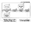
- FIG. 1 is an outline lineblock diagram of a train operation control device of an embodiment.
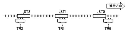
- FIG. 2 is an explanatory diagram of the relationship between trains and stations.
- FIG. 3 is an explanatory diagram of the states of the own train, the preceding train, and the succeeding train.
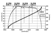
- FIG. 4 is an explanatory diagram of a speed limit calculation method using a preceding train.
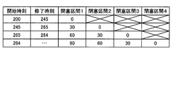
- FIG. 5 is an explanatory diagram of a speed limit setting example in a state corresponding to FIG.
- FIG. 6 is a flowchart for creating an energy-saving operation curve according to the embodiment.
- FIG. 7 is a flowchart of a process for creating the shortest time operation curve.
- FIG. 8 is an explanatory diagram of the usable conditions of the maximum acceleration and the maximum deceleration.
- FIG. 1 is an outline lineblock diagram of a train operation control device of an embodiment.
- FIG. 2 is an explanatory diagram of the relationship between trains and stations.
- FIG. 3 is an explanatory diagram of the states of the
- FIG. 9 is a process flowchart of an acceleration limit curve creation process.
- FIG. 10 is a process flowchart of a deceleration limit curve creation process.
- FIG. 11 is a process flowchart of a process for creating the shortest time operation curve.
- FIG. 12 is a process flowchart of an energy saving operation curve creation process.
- FIG. 13 is a graph (x ⁇ t) where time is plotted on the horizontal axis and train position is plotted on the vertical axis.
- FIG. 14 is an explanatory diagram of the speed condition.
- FIG. 15A is an explanatory diagram (part 1) of the quantization process.
- FIG. 15B is an explanatory diagram (part 2) of the quantization process.
- FIG. 16 is an explanatory diagram of a setting example of the speed limit value.
- FIG. 2 is an explanatory diagram of the relationship between trains and stations.
- the train travels forward in the traveling direction of the own train TR1.
- the train just before is the preceding train.
- the train immediately after traveling in the rearward direction of the own train TR1 is defined as a subsequent train (rear train).
- the operation control of the own train TR1 is performed according to the operation status of the own train TR1, the preceding train, and the subsequent train.
- the train information used to determine the departure time of the current station of the own train TR1 and the arrival time of the next station is information on only the preceding train and the subsequent train.
- the train operation control device 100 includes a diagram database (DB) 101 in which information after allocation of vehicles to the diagram (diagram: operation plan diagram) of the day is stored, and a train subject to operation control that has arrived at the station.
- DB diagram database
- the train operation control device 100 includes a past operation interval for the timetable, a time interval / stop time database (DB) 103 that stores the actual value of the stop time at the station, and each time for each time by the preceding train TR0.
- a speed limit calculation unit 104 for determining a speed limit at the closed approach position, a characteristic of each notch with respect to a boarding rate of a vehicle traveling on the route, a characteristic of a motor / inverter, a speed limit for the position of the route, a gradient with respect to the position, and the route
- DB vehicle / route database
- the train operation control apparatus 100 uses the calculation result of the speed limit calculation unit 104 as a constraint condition, and creates an operation curve that creates the operation curve with the smallest cumulative energy consumption related to traveling from the current station of the own train TR1 to the preceding station.
- Unit 106 and an operation information extraction unit 107 that extracts a speed limit at each blockage approach position (blockage section entry position) using the calculation result of the operation curve creation unit 106.
- the departure time / arrival time calculation unit 102 arrives at the arrival time of the own train TR1 that has arrived, the current position of the subsequent train TR2, and the station from which the subsequent train TR2 has departed (rear station ST2). And the departure time thereof, the scheduled arrival time of the next station of the subsequent train TR2 (current station ST1), the current position of the preceding train TR0 and the station from which the preceding train TR0 departed (front station ST0), its departure time, and the next of the preceding train TR0 Get the expected arrival time at the station (input).
- the departure time / arrival time calculation unit 102 acquires the information (data) described above, the departure time / arrival time calculation unit 102 refers to the diamond DB 101 and acquires the scheduled arrival time of the own train TR1 assumed in the diamond. Then, the departure time / arrival time calculation unit 102 calculates the difference between the scheduled arrival time registered in the diagram DB 101 and the arrival time in actual operation, and determines whether or not the own train TR1 is delayed.
- the departure time / arrival time calculation unit 102 calculates the scheduled departure time of the current station ST1.
- the scheduled departure time of the current station ST1 is a time obtained by adding the stop time to the arrival time of the current station ST1.
- a value stored (set) in advance in the diamond DB 101 is used, or an average value of actual train values at the same scheduled arrival time in the past is used.
- Delay time of own train TR1 Actual arrival time of own train TR1 at current station ST1-Expected arrival time of own train TR1 at current station ST1 on the diagram
- Time margin for own train TR1 Time required for own train TR1 to travel from the current station ST1 to the preceding station ST0 on the diamond -The shortest time required for the own train TR1 to travel from the current station ST1 to the preceding station ST0
- Stop time of the own train TR1 at the current station ST1 Total time and adjustment time required for own train TR1 to get on and off passengers at station ST1
- Delay time of preceding train TR0 Actual arrival time of the preceding train TR0 to the preceding station ST0-Scheduled arrival time of the preceding train TR0 to the preceding station ST0 on the diamond (5)
- Blocking opening time of the preceding station ST0 of the preceding train TR0 the preceding train TR0 is ahead Time to pass blockage at station ST0 position (6)
- Stop time at preceding station ST0 of preceding train TR0 total time required for passengers to get on and off at preceding station ST0 and adjustment time
- the delay time of the subsequent train TR2 and the stop time at the rear station ST2 of the subsequent train TR2 are required.
- Delay time of following train TR2 Actual arrival time of the subsequent train TR2 to the rear station ST2-Scheduled arrival time of the subsequent train TR2 to the rear station ST2 on the diagram (8)
- Stop time of the subsequent train TR2 at the rear station ST2 Subsequent train TR2 is the rear station Total time and adjustment time required for passengers to get on and off at ST2
- the train operation control apparatus 100 calculates the train operation control apparatus 100.
- the planned departure time when the own train TR1 leaves the current station ST1 is calculated.
- the estimated arrival time at which the train TR1 arrives at the front station ST0 and the time required for the own train TR1 to travel from the current station ST1 to the front station ST0 (running time) are calculated.
- Traveling time Current scheduled departure time at station ST1-Expected arrival time at front station ST0
- the train operation control apparatus 100 calculates an energy saving operation curve for the own train TR1 to travel from the current station ST1 to the preceding station ST0 according to the following procedure.
- the scheduled departure time of the current station ST1 of the own train TR1 and the scheduled arrival time of the preceding station ST0 of the own train TR1 are determined in consideration of the operation status of the preceding train TR0 and the subsequent train TR2.
- the current situation of the own train TR1, the preceding train TR0, and the succeeding train TR2 is evaluated by the delay time.
- each train is defined as follows using the delay time td and the scheduled allowable time ⁇ ( ⁇ > 0) of the own train TR1, the preceding train TR0, or the succeeding train TR2.
- the on-time allowable time ⁇ is a parameter that represents a time range that is treated as on-time.
- time adjustment is performed by extending the stop time at the station where the arrival arrived early, and the station departs from the station where the arrival arrived at the scheduled departure time set on the diagram. I am going to do it.
- both early arrivals and on-time departures can be made at the scheduled departure time set on the timetable at the relevant station, so the state at the time of departure from the station can be regarded as the same. Therefore, the state of the own train TR1, the state of the preceding train TR0, and the state of the subsequent train TR2 can be processed separately in two cases: early arrival or on time, and delay.
- FIG. 3 is an explanatory diagram of the states of the own train, the preceding train, and the succeeding train.
- State ID 1: When the subsequent train TR2, the own train TR1, and the preceding train TR0 are all arrived early or on time.
- the traveling time of the own train TR1 is as follows.
- the train operation control device 100 of the own train TR1 departs at the scheduled departure time of the current station ST1 on the diagram + (the margin time of the own train TR1 ⁇ the delay time of the subsequent train TR2), and on the diagram Plan to arrive at the scheduled arrival time at the next station. At that time, the train operation control device 100 determines the travel time of the own train TR1 as follows.
- the vehicle travels earlier than the travel time on the diagram by (the margin time of own train TR1 ⁇ the delay time of the following train TR2). Therefore, by converting the remaining time in advance to travel time, the energy consumption increases, but the driving time interval with the subsequent train TR2 is increased, and the person who gets on the subsequent train TR2 Can be absorbed by the own train TR1, and the cause of the increase in delay due to the concentration of boarding on the subsequent train TR2 can be reduced.
- the vehicle travels earlier by (the margin time of own train TR1 ⁇ the delay time of own train TR1). Therefore, by converting the remaining time in advance to the running time, the energy consumption increases, but the delay of the own train TR1 does not affect the subsequent train TR2, and the preceding station ST0. The delay can be recovered by.
- the train operation control apparatus 100 calculates the scheduled departure time of the current station ST1 of the own train TR1, the scheduled arrival time of the preceding station ST0 of the own train TR1, and the traveling time of the own train TR1 as follows: It shall be as follows.
- the block opening time of the preceding station ST0 of the preceding train TR0 is after the scheduled arrival time of the preceding station ST0 on the diagram of the own train TR1 has elapsed.
- the block opening time of the preceding station ST0 of the preceding train TR0 is after the scheduled arrival time of the preceding station ST0 on the diagram of the own train TR1 (the blocking opening time of the preceding station ST0 of the preceding train TR0> the preceding station on the diagram of the own train TR1.
- ST0 (scheduled arrival time).
- the own train TR1 cannot operate in the running time set on the diagram. Therefore, the train operation control apparatus 100 sets the scheduled arrival time of the next station of the own train TR1 and the traveling time of the own train TR1 as follows.
- Scheduled arrival time of the next station of the own train TR1 Blocking opening time of the preceding station ST0 of the preceding train TR0 ⁇
- Running time on the diamond The train operation control device 100 is longer than the running time on the diamond and is blocked due to the presence of the preceding train TR0 Considering the speed limitation in the section, the energy saving operation curve is created by the traveling time of the above-mentioned own train TR1.
- the train operation control apparatus 100 sets the scheduled departure time of the current station ST1 of the own train TR1 and the traveling time of the own train TR1 as follows.
- the delay time of the following train TR2 exceeds the time obtained by subtracting the delay time of the own train TR1 from the margin time of the own train TR1.
- the delay time of the following train TR2 exceeds the time obtained by subtracting the delay time of the own train TR1 from the margin time of the own train TR1 [the delay time of the subsequent train TR2> (the margin time of the own train TR1 ⁇ the delay time of the own train TR1)
- the train operation control apparatus 100 sets the scheduled departure time of the current station ST1 of the own train TR1, the scheduled arrival time of the front station ST0 of the own train TR1, and the traveling time of the own train TR1 as follows.
- the train operation control device 100 determines the current station ST1 of the own train TR1.
- the scheduled departure time and the scheduled arrival time of the front station ST0 of the own train TR1 are as follows.
- the train operation control device 100 determines the current station of the own train TR1.
- the scheduled departure time of ST1, the scheduled arrival time of the next station of the own train TR1, and the running time of the own train TR1 are as follows.
- the train operation control apparatus 100 sets the delay time of the following train TR2, the next station block opening time of the preceding train TR0, and the scheduled arrival time of the next station on the timetable of the own train TR1. Based on the scheduled departure time of the current station ST1 of the own train TR1, the scheduled arrival time of the next station of the own train TR1, and the traveling time of the own train TR1 are as follows.
- the delay time of the following train TR2 is equal to or less than the time obtained by subtracting the scheduled arrival time of the next station on the timetable of the own train TR1 from the next station block opening time of the preceding train TR0.
- the delay time of the succeeding train TR2 is equal to or less than the time obtained by subtracting the scheduled arrival time of the next station on the diamond of the own train TR1 from the next station block opening time of the preceding train TR0 [delay time of the following train TR2 ⁇ (preceding train TR0
- the train operation control device 100 determines the delay time of the subsequent train TR2, the next station block opening time of the preceding train TR0, and Based on the scheduled arrival time of the next station on the schedule of the own train TR1, the scheduled departure time of the current station ST1 of the own train TR1, the scheduled arrival time of the next station of the own train TR1, and the travel time of the own train TR1 are as follows: Street.
- the delay time of the subsequent train TR2 exceeds the time obtained by subtracting the scheduled arrival time of the next station on the timetable of the own train TR1 from the next station block opening time of the preceding train TR0.
- the delay time of the following train TR2 exceeds the time obtained by subtracting the scheduled arrival time of the next station on the timetable of the own train TR1 from the next station block opening time of the preceding train TR0 [delay time of the following train TR2> (preceding train The next station block opening time of TR0-the scheduled arrival time of the next station on the timetable of the own train TR1)]
- the train operation control device 100 determines the delay time of the following train TR2 and the next station block opening time of the preceding train TR0.
- the block opening time of the preceding station ST0 of the preceding train TR0 adds the delay time of the own train TR1 to the scheduled arrival time of the preceding station ST0 on the timetable of the own train TR1, and the margin time of the own train TR1 If it is before the time minus.
- the block opening time of the preceding station ST0 of the preceding train TR0 is before the time when the delay time of the own train TR1 is added to the scheduled arrival time of the preceding station ST0 on the timetable of the own train TR1 and the margin time of the own train TR1 is subtracted [Blocking opening time of the preceding station ST0 of the preceding train TR0 ⁇ (planned arrival time of the preceding station ST0 on the diamond of the own train TR1 + delay time of the own train TR1 ⁇ allowance time of the own train TR1)]
- the train operation control device 100 determines the scheduled departure time of the current station ST1 of the own train TR1 and the scheduled arrival time of the preceding station ST0 of the own train TR1 based on the delay time of the own train TR1 and the spare time of the own train TR1. And the traveling time of the own train TR1 is as follows.
- the train operation control device 100 determines the current station of the own train TR1.
- the scheduled departure time of ST1, the scheduled arrival time of the front station ST0 of the own train TR1, and the traveling time of the own train TR1 are as follows.
- the train operation control device 100 determines the current time of the own train TR1.
- the scheduled departure time of the station ST1, the scheduled arrival time of the station ST0 ahead of the own train TR1, and the traveling time of the own train TR1 are as follows.
- the block opening time of the preceding station ST0 of the preceding train TR0 adds the delay time of the own train TR1 to the scheduled arrival time of the next station on the timetable of the own train TR1, and the spare time of the own train TR1 is calculated. When the deducted time is exceeded.
- the block opening time of the preceding station ST0 of the preceding train TR0 exceeds the time obtained by adding the delay time of the own train TR1 to the scheduled arrival time of the next station on the diamond of the own train TR1 and subtracting the spare time of the own train TR1 If [the closing opening time of the preceding station ST0 of the preceding train TR0> (scheduled arrival time of the next station on the diamond of the own train TR1 + delay time of the own train TR1 ⁇ allowance time of the own train TR1)]
- the train operation control apparatus 100 sets the scheduled departure time of the current station ST1 of the own train TR1, the scheduled arrival time of the preceding station ST0 of the own train TR1, and the traveling time of the own train TR1 as follows.
- Running time of own train TR1 Scheduled arrival time of station ST0 ahead of own train TR1 ⁇ Scheduled departure time of current station ST1 of own train TR1
- [8] State ID 8: When the subsequent train TR2, the own train TR1, and the preceding train TR0 are all delayed. When all of the own train TR1, the preceding train TR0, and the following train TR2 are delayed, the train operation control device 100 of the own train TR1 includes the delay time of the own train TR1 itself, and the delay between the following train TR2 and the preceding train TR0. In consideration of all the above, the scheduled departure time of the current station ST1 and the scheduled arrival time of the preceding station ST0 must be determined.
- the train operation control device 100 of the own train TR1 determines the scheduled departure time of the current station ST1 in consideration of the block opening time of the preceding station ST0 of the preceding train TR0.
- the block opening time of the preceding station ST0 of the preceding train TR0 adds the delay time of the own train TR1 to the scheduled arrival time of the preceding station ST0 on the timetable of the own train TR1, and the spare time of the own train TR1 If before the time minus.
- the block opening time of the preceding station ST0 of the preceding train TR0 is before the time when the delay time of the own train TR1 is added to the scheduled arrival time of the preceding station ST0 on the timetable of the own train TR1 and the margin time of the own train TR1 is subtracted. If [the block opening time of the preceding station ST0 of the preceding train TR0 ⁇ (scheduled arrival time of the preceding station ST0 on the diamond of the own train TR1 + delay time of the own train TR1 ⁇ allowance time of the own train TR1)]
- the train operation control apparatus 100 sets as follows based on the delay time of the subsequent train TR2.
- the delay time of the following train TR2 is equal to or less than the time obtained by subtracting the delay time of the own train TR1 from the margin time of the own train TR1.
- the running time is as follows.
- the train operation control apparatus 100 sets the scheduled departure time of the current station ST1 of the own train TR1, the scheduled arrival time of the next station of the own train TR1, and the traveling time of the own train TR1 as follows.
- the block opening time of the preceding station ST0 of the preceding train TR0 adds the delay time of the own train TR1 to the scheduled arrival time of the preceding station ST0 on the diamond of the own train TR1, and the spare time of the own train TR1 If the time after subtracting is exceeded.
- the train operation control device 100 sets as follows based on the delay time of the subsequent train TR2.
- the delay time of the following train TR2 is equal to or less than the time obtained by subtracting the scheduled arrival time of the next station on the timetable of the own train TR1 and the delay time of the own train TR1 from the next station block opening time of the preceding train TR0. If it is.
- the delay time of the following train TR2 is equal to or less than the time obtained by subtracting the scheduled arrival time of the next station on the diamond of the own train TR1 and the delay time of the own train TR1 from the next station block opening time of the preceding train TR0.
- the delay time ⁇ (the next station block opening time of the preceding train TR0 ⁇ the scheduled arrival time of the next station on the timetable of the own train TR1 ⁇ the delay time of the own train TR1)]
- the train operation control device 100 The scheduled departure time of the current station ST1 of the train TR1, the scheduled arrival time of the next station of the own train TR1, and the running time of the own train TR1 are as follows.
- the delay time of the following train TR2 is the time obtained by subtracting the scheduled arrival time of the next station on the diamond of the own train TR1 and the delay time of the own train TR1 from the next station block opening time of the preceding train TR0. If it exceeds.
- the delay time of the following train TR2 exceeds the time obtained by subtracting the scheduled arrival time of the next station on the diamond of the own train TR1 and the delay time of the own train TR1 from the next station block opening time of the preceding train TR0 [following train TR2 Delay time> (the next station block opening time of the preceding train TR0-the scheduled arrival time of the next station on the timetable of the own train TR1-the delay time of the own train TR1)], the train operation control device 100
- the scheduled departure time of the current station ST1 of TR1, the scheduled arrival time of the next station of the own train TR1, and the running time of the own train TR1 are as follows.
- the speed limit calculating unit 104 creates an energy saving operation curve of the own train TR1. Calculate the speed limit depending on the time required. The speed limit by the preceding train TR0 is calculated based on the operation curve of the preceding train TR0.
- the creation method will be specifically described with reference to FIG.
- FIG. 4 is an explanatory diagram of a speed limit calculation method for the preceding train TR0.
- the blockage section existing between the station (4700 [m] point) from which the preceding train TR0 departed and the arrival station (6750 [m] point) can be known at the same time.
- the train operation control device 100 calculates whether the train has passed from the blockage section with the elapsed time from the time when the preceding train TR0 departed from the station (here, 200 seconds is the departure time). It is only necessary to see the transit time at a position advanced by the train length from each blockage.
- each of the first to third closed sections is calculated as follows. Passed through first closed section CA1: 245 seconds Passed through second closed section CA2: 265 seconds Passed through third closed section CA3: 284 seconds
- FIG. 5 is an explanatory diagram of a speed limit setting example in a state corresponding to FIG. Subsequently, the train operation control apparatus 100 sets the speed limit of the own train TR1 for the elapsed time of each blocked section.
- the speed limit is set to 0, 30, 60, 90 [km / h] from the side closer to the existing train.
- FIG. 5 is an example, and the method of determining the speed limit differs depending on each railway operator.
- the speed limit of the own train TR1 in the first closed section CA1 is 0 km, That is, the vehicle stops and entry is prohibited.
- the speed limit of the own train TR1 in the second closed section CA2 is 0 km, that is, stops. Entry is prohibited.
- the speed limit of the own train TR1 in the first closed section CA1 adjacent to the front side of the second closed section CA2 is 30 km.
- the speed limit of the own train TR1 in the third closed section CA3 is 0 km, that is, stops. Entry is prohibited. Moreover, the speed limit of the own train TR1 in the second closed section CA2 adjacent to the front side of the third closed section CA3 is 30 km. Further, since the first closed section CA1 is provided via the second closed section CA2 with respect to the third closed section CA3, the speed limit of the own train TR1 is 60 km higher than the second closed section CA2. .
- the speed limit of the own train TR1 in the fourth closed section CA4 is 0 km, that is, stops, and entry is prohibited.
- the speed limit of the own train TR1 in the third closed section CA3 adjacent to the front side of the fourth closed section CA4 is 30 km.
- the speed limit of the own train TR1 in the second closed section CA2 is provided via the third closed section CA3 with respect to the fourth closed section CA4, the speed limit of the own train TR1 is 60 km higher than the third closed section CA3.
- the speed limitation of the own train TR1 is the second closed section CA2. It becomes 90 km higher than the section CA2.
- the operation curve creation unit 106 of the train operation control device 100 next, the current station ST1 and the preceding station ST0 with the travel time set by the own train TR1. Create an energy saving operation curve.
- the energy saving operation curve of a train is a state at the departure station expressed by an equation of motion including travel resistance and gradient resistance as constraints, an elapsed time t from the departure, a speed v, and a distance x from the departure station (
- T is the elapsed time required from the departure station to the arrival station
- X is the distance between the departure station and the arrival station.
- the evaluation function is obtained by solving an optimal control problem with the sum E (cumulative energy consumption) of energy consumed between the departure station and the arrival station.
- the control variable that specifies the motion of the train is a notch that specifies acceleration and deceleration.
- a widespread train realizes acceleration / deceleration of a train by a plurality of notches, and the driving curve can be regarded as a multistage decision making problem as to which notch is selected and operated at each time.
- a problem that arises when solving a multistage decision-making problem is a combination explosion of solution candidates.
- the combination explosion will be briefly described. For example, when there are 10 notch choices and an operation curve with a running time of 100 seconds is created with a minimum control time unit of 1 second, a solution satisfying the constraint must be found out of 10 100 solution candidates. . It is impossible to find a solution that satisfies the constraints on squeezing from within this time range.
- an optimum solution search method using dynamic programming is to define the train's (time, speed, position) state on a grid point, and search for a path with the smallest accumulated energy consumption at that grid point. At that time, when there are a plurality of routes that reach a certain state (t, v, x), only the route with the smallest accumulated energy consumption is stored, and the search is continued.
- the state space is divided into a grid in advance, but generally it is rare to move from a grid point to a grid point. For this reason, it is assumed that some corrections are made to move to the grid point when it is not on the grid point. In this method, when the correction to the lattice points increases, there is a problem that the error becomes larger than the optimum solution.
- each time (stage) checks whether it can be a candidate for an acceptable solution (pruning) and solves each time the stage is advanced.
- a method for generating candidates is proposed.
- pruning is a general-purpose method for solving combinatorial optimization problems known in the field of operations research.
- solution candidates are generated, and in the pruning operation, solution candidates that cannot be the optimal solution are pruned and deleted from the solution candidate list.
- the optimum solution is searched while repeating the generation operation and the pruning operation.
- FIG. 6 is a flowchart for creating an energy-saving operation curve according to the embodiment.
- the driving curve creating unit 106 refers to the vehicle / route DB 105 and based on the input vehicle information and inter-station information, the driving curve. Data necessary for creation is acquired (step S101). Subsequently, the driving curve creation unit 106 creates the driving curve of the shortest time between the input stations (step S102).
- FIG. 7 is a flowchart of a process for creating the shortest time operation curve.
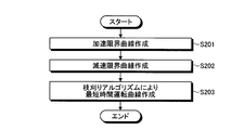
- the shortest time operation polarity creation processing is roughly divided into acceleration limit curve creation processing (step S201), deceleration limit curve creation processing (step S202), and shortest time operation curve creation processing (step S203) using a pruning algorithm. Has been.
- the shortest time control is controlled by the maximum acceleration or maximum deceleration called “bang-bang control”.
- the speed is mainly limited by the position during train operation, it cannot always be controlled only by the maximum acceleration and the maximum deceleration. Therefore, the range in which the train can be moved with maximum acceleration and maximum deceleration is obtained.
- FIG. 8 is an explanatory diagram of the usable conditions of the maximum acceleration and the maximum deceleration.
- FIG. 9 is a process flowchart of an acceleration limit curve creation process.
- FIG. 10 is a process flowchart of a deceleration limit curve creation process.
- the maximum acceleration and maximum deceleration can be used during train operation in four cases, Case 1 to Case 4, as shown in FIG. Case 1: Use the maximum acceleration when leaving the departure station Case 2: Use the maximum deceleration when arriving at the arrival station Case 3: Use the maximum acceleration when the speed limit increases in the direction of travel Case 4: Use the speed limit in the direction of travel Use maximum deceleration when decreasing with
- struct velocity_limitation ST [2] ⁇ 0,0 ⁇ , ⁇ x2, v2 ⁇ ;
- struct velocity_limitation ST [2] ⁇ X1, v2 ⁇ , ⁇ X, 0 ⁇ ; become.
- step S201 first, (speed, position) when using the maximum acceleration and the maximum deceleration are calculated.
- the curves in cases 1 to 4 shown in FIG. 8 are called an acceleration limit curve and a deceleration limit curve, respectively.
- the acceleration limit curve can be easily obtained by giving initial conditions of speed and position using the maximum acceleration.
- the operation curve creation unit 106 initializes a variable s and sets the initial value to 0 (step S ⁇ b> 401).
- the running curve creation unit 106 adds 1 to the time i (step S403). Subsequently, the running curve creation unit 106 solves the equation of motion for the state (v (i), x (i)) at time i with a maximum acceleration notch (corresponding to a notch position where the maximum acceleration can be obtained), Calculate (step S404).
- the driving curve creation unit 106 determines whether the speed v (i) at the time i exceeds the speed limit vmax, that is, v (i)> vmax Alternatively, the position x (i) at time i is the target position ST [s]. It is determined whether or not the position has been exceeded (step S405).
- step S405 the speed v (i) at the time i does not exceed the speed limit vmax, and the position x (i) at the time i is the target position ST [s].
- step S405 the operation curve creation unit 106 proceeds to step S403 again, and thereafter repeats the same process.
- step S405 the speed v (i) at time i exceeds the speed limit vmax, or the position x (i) at time i is the target position ST [s].
- step S406 If it is determined in step S406 that the target position of the acceleration limit curve has not been reached (step S406; No), the operating curve creation unit 106 adds 1 to the variable s (step S407), and the process returns to step S402. Thereafter, the same processing is repeated. If it is determined in step S406 that the target position of the acceleration limit curve has been reached (step S406; Yes), the operation curve creation unit 106 ends the acceleration limit curve creation processing.
- the driving curve creation unit 106 calculates a deceleration limit curve in the same manner as the calculation of the acceleration limit curve (step S202).
- the deceleration limit curve an initial condition that satisfies the terminal condition is searched by an iterative method.
- an allowable range ( ⁇ and ⁇ ) is given to the termination condition, and an initial condition that satisfies the range is obtained.
- the running curve creation unit 106 adds 1 to the time i (step S503). Then, the operation curve creation unit 106 calculates the train state at time i by solving the equation of motion using the maximum deceleration notch (step S504). Subsequently, the operation curve creation unit 106 determines whether or not the speed v (i) at the time i satisfies the following expression corresponding to the allowable value ⁇ (step S505). 0 ⁇ v (i) ⁇
- step S505 ⁇ ⁇ v (i) If it is (step S505; No), the operation curve creation unit 106 shifts the process to step S503 again and performs the same process.
- step S505 0 ⁇ v (i) ⁇ If it is (step S505; Yes), the operation curve creation unit 106 determines whether or not the position x (i) at time i satisfies the following expression corresponding to the allowable value ⁇ (step S506).
- step S506 the operation curve creation unit 106 x (i) ⁇ Distance It is determined whether or not (step S507).
- step S507 x (i) ⁇ Distance (Step S507; Yes)
- the operation curve creation unit 106 a (a + b) /2.0
- step S508 the same process is performed thereafter.
- step S510 If it is determined in step S510 that the target position of the deceleration limit curve has not been reached (step S510; No), the operation curve creation unit 106 adds 1 to the variable s (step S511), and the process returns to step S502. Thereafter, the same processing is repeated. If it is determined in step S510 that the target position of the deceleration limit curve has been reached (step S510; Yes), the operation curve creation unit 106 ends the deceleration limit curve creation processing.
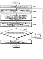
- FIG. 11 is a process flowchart of a process for creating the shortest time operation curve.
- the variable previous_state, the variable current_state, and the variable middle_state shown in FIG. 11 will be described.
- a control program developed in a high-level language such as C ++ or JAVA (registered trademark) is assumed as a control program for realizing the operation curve creation process.
- C ++ and JAVA a variable-length array whose array size can be changed depending on the number of elements can be used. For this reason, in this embodiment, the solution candidate at each time shall be expressed using a variable length array.
- a solution candidate is struct phase ⁇ double position; // position double velocity; // speed double energy; // instantaneous energy consumption double total_energy; // cumulative energy consumption int notch [500]; // notch number int gt int gt int / Notch switching frequency int notch_continuous_time; // current notch duration ⁇ ; It is expressed by a structure like
- the solution candidate may be expressed as
- the running curve creation unit 106 solves the equations of motion (differential equations) at all notches for each solution candidate at the elapsed time t + 1, and determines the solution candidates at the elapsed time t (number of solution candidates at the elapsed time t) ⁇ (Number of notch selections) are created, the solution candidates are stored as a variable current_state, and the variable previous_state is released (cleared) from the memory (step S602).
- the operation curve creation unit 106 checks whether the speed of each solution candidate of the variable current_state is smaller than the acceleration limit curve, the deceleration limit curve, and the speed limit based on the position, and only the smaller one is set to the variable middle_state.
- the variable current_state is released (cleared) from the memory (step S603).
- the operation curve creation unit 106 sorts the position of the variable middle_state in descending order (in descending order), stores the top K in the variable previous_state, and releases (clears) the variable middle_state from the memory (step S604).
- the operation curve creation unit 106 repeats until the condition with an allowable range for the end condition is satisfied (step S605; Yes), and for the elapsed time t when a solution candidate that satisfies the condition has appeared. T + 1 is set as the shortest running time (step S607). If the condition is not satisfied in the determination in step S605 (step S605; No), 1 is added to the elapsed time t (increment) (step S606), and the process proceeds to step S602 again. repeat.
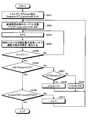
- FIG. 12 is a process flowchart of an energy saving operation curve creation process.
- the operation curve creation unit 106 creates an energy saving operation curve for the travel time T (step S103). For this reason, the operation curve creation unit 106 sets the result of the shortest time operation curve described above as the upper limit value, and the result of moving the result of the shortest time operation curve in the time direction by the travel time T as the lower limit value (step S700). .
- the running curve creation unit 106 solves the equations of motion (differential equations) at all notches for each solution candidate at the elapsed time t + 1, and determines the solution candidates at the elapsed time t (number of solution candidates at the elapsed time t) ⁇ (Number of notch selections) are created, the solution candidates are saved as a variable current_state, and the variable previous_state is released (cleared) from the memory (step S702).
- the operation curve creation unit 106 saves the variable current_state that satisfies the solution conditions (position, speed, number of notch switching, notch duration) in the variable middle_state, and releases (clears) the variable current_state from the memory. (Step S703).
- the operation curve creation unit 106 sorts the variable middle_state at the elapsed time t + 1 by state (quantized position, quantized speed, number of notch switching). Then, in the state regarded as the same state, the one with the smallest accumulated energy consumption is selected as one of the solution candidates, stored in the variable previous_state, and the variable middle_state is released (cleared) from the memory (step S704).
- the shortest travel time T min is a travel time (shortest travel time) when traveling between the stations in the shortest time.
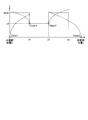
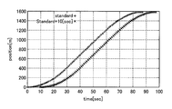
- FIG. 13 is a graph (x ⁇ t) where time is plotted on the horizontal axis and train position is plotted on the vertical axis.
- the upper graph shows the relationship between the position x and the elapsed time t when traveling at the shortest travel time Tmin , and the lower graph waits 10 seconds at the departure station and travels at the shortest travel time Tmin . In this case, the relationship between the position x and the elapsed time t is shown.
- the shortest travel time Tmin is that the vehicle has traveled by making the best use of the performance of the vehicle, and if it has the same vehicle characteristics, it means that it cannot travel any faster. That is, when the vehicle characteristics are determined, the shortest travel time Tmin is uniquely obtained. Therefore, when the position x is closer to the departure station than the lower graph at a certain time, it means that the travel time T min +10 cannot arrive at the arrival station (next station).
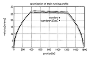
- FIG. 14 is an explanatory diagram of the speed condition.
- the curve shown in FIG. 14 is called an operation curve.
- the speed V at the position x corresponding to the travel time T is written as V T [x].
- V T [x] the speed V at the position x corresponding to the travel time T.
- the operation curve of the travel time T exists inside the shortest time operation curve.
- the result of the shortest time operation curve also knows only the speed and position of the train at the discrete elapsed time t, and it is difficult to calculate similarly to V Tmin [x].
- the number of times of notch switching up to that time is counted as a solution candidate selection condition, and if it exceeds a certain value, it is excluded from the solution candidates. For example, if the number of times of notch switching is set to 10 before the arrival at the next station for traveling between certain stations, a variable current_state [i]. Only the variable current_state [i] satisfying the condition of change_count ⁇ 10 is stored in the variable middle_state.
- the notch continuation condition is a condition for notch switching at short time intervals. If the notch continuation condition is 5 seconds or more, a variable current_state [i]. Only the variable current_state [i] satisfying the condition of notch_continuous_time ⁇ 5 is stored in the variable middle_state.
- step S703 determination is made for all solution candidates using the position condition, speed condition, notch switching frequency condition, and notch duration condition, and only those satisfying these conditions are stored in the variable middle_state. I am trying to do it. Further, in step S704, the state (t, v (t), x (t)) at the elapsed time t + 1 in the variable middle_state in which the solution candidates satisfying the respective conditions in step S703 are stored is quantized with respect to speed and position. Then, the quantized speed and position, the number of notch switching, and the notch duration are grouped, and only the one with the smallest cumulative energy consumption among the grouping is left as a solution candidate. Further, in the present embodiment, it is possible to easily perform expansion such as selecting a notch so that the instantaneous energy consumption does not exceed the upper limit value.
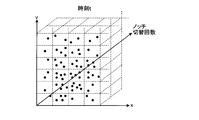
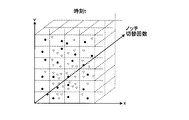
- FIG. 15A is an explanatory diagram (part 1) of the quantization process.
- FIG. 15B is an explanatory diagram (part 2) of the quantization process. Since the position and velocity are continuous values, in order to quantize, for example, the value is quantized by a certain width such as 1 [m] for the position and 0.1 [m / sec] for the velocity, Since the upper limit Upper [t] and the lower limit Lower [t] at time t are determined, there is a method in which Upper [t] and Lower [t] are quantized by dividing into N. Here, the description will be made on the assumption that the position and velocity are quantized to a certain width.
- the solution candidate states are defined on four axes. Since it is difficult to show, here, description will be made with three conditions: a position condition, a speed condition, and a notch switching frequency condition.
- n (t) is the number of times of notch switching at the elapsed time t.
- step S705 the operation curve creation unit 106 determines whether the elapsed time t matches the travel time T. If not (step S705; No), the operation curve generation unit 106 proceeds to step S706, increments the elapsed time t, and again. The process proceeds to step S702.
- step S705 if the elapsed time t coincides with the travel time T (step S705; Yes), the operation curve creation unit 106 selects the solution with the smallest accumulated energy consumption from the solution candidates as the optimal solution ( Step S707).
- the accumulated energy consumption may be sorted in ascending order (smallest order) and selected from among them.
- the operation curve creation unit 106 sets the solution having the smallest cumulative energy consumption + penalty (v, x) as the optimum solution.
- penalty (v (T), x (T)) is an error penalty between the state (T, v (T), x (T)) and the terminal state (T, 0, X) at the elapsed time t.
- v (T), x (T) is an error penalty between the state (T, v (T), x (T)) and the terminal state (T, 0, X) at the elapsed time t.
- the operation curve creation unit 106 uses the result of the energy saving operation curve of the travel time T as the operation curve creation result storage unit.
- the data is stored in a hard disk drive, semiconductor memory device, etc. (not shown) (step S104).
- the driving information extraction unit 107 extracts the speed limit value at each blockage approach point using the created energy saving driving curve, and communicates the extracted speed limit value to the traffic light.
- FIG. 16 is an explanatory diagram of a setting example of the speed limit value.
- the operation is performed to recover the delay with respect to the delay that occurs during the actual operation, and at the same time, the delay of the preceding train is determined by the stop signal determined by the position of the preceding train. Energy saving can be achieved by preventing the host train TR1 from performing unnecessary deceleration that stops.
- the train operation control device of this embodiment includes a control device such as a CPU, a storage device such as a ROM (Read Only Memory) and a RAM, an external storage device such as an HDD and a CD drive device, and a display device such as a display device.
- a control device such as a CPU
- a storage device such as a ROM (Read Only Memory) and a RAM
- an external storage device such as an HDD and a CD drive device
- a display device such as a display device.
- an input device such as a keyboard and a mouse is provided, and a hardware configuration using a normal computer can be employed.
- the control program executed by the train operation control device of this embodiment is a file in an installable or executable format, such as a CD-ROM, a flexible disk (FD), a CD-R, a DVD (Digital Versatile Disk), etc.
- the program is provided by being recorded on a computer-readable recording medium.
- control program performed with the train operation control apparatus of this embodiment may be provided by storing on a computer connected to networks, such as the internet, and downloading via a network.
- control program performed with the train operation control apparatus of this embodiment may be provided or distributed via networks, such as the internet.
- control program of the train operation control apparatus of this embodiment may be previously incorporated in ROM etc. and provided.
Landscapes
- Engineering & Computer Science (AREA)
- Mechanical Engineering (AREA)
- Train Traffic Observation, Control, And Security (AREA)
- Electric Propulsion And Braking For Vehicles (AREA)
Abstract
実施形態の列車運行制御装置の運転曲線作成部は、自列車が次の出発駅となるいずれかの駅に到着した時点において、前記自列車の直前を走行する列車である先行列車及び前記自列車の直後を走行する列車である後続列車のそれぞれの次の出発駅を予め設定された運転ダイヤ通りに出発することが可能な状態にあるか否かに基づいて、前記自列車が、前記到着した駅を出発してから次の停車駅に到着するまでの運転曲線を、累積消費エネルギーを考慮して作成するので、遅延が発生した場合においても、遅延の回復と無駄な消費エネルギーの増加を防止することによる省エネを実現できる。
Description
本発明の実施形態は、列車運行制御装置、制御方法及び制御プログラムに関する。
近年の電力不足からエネルギー効率のよい鉄道に対しても更なる省エネが求められている。鉄道における省エネとは空調、照明等の補機をエネルギー効率のよい機器に変更することや、列車の走行時のエネルギーを削減することなどである。特に列車の走行時のエネルギーを削減するためには、力行に要するエネルギーを削減し、エネルギーの回収効率のよい状況を作って回生ブレーキをかけるなどの方法が提案されている。
これらを実現すると結果的に列車はゆっくり走ることになり、なるべく次の駅までゆっくり走ること自体がそのまま省エネルギー(以下、省エネという)につながる。
「宮武,高:動的計画法を用いた列車運転曲線最適化問題の求解法,電気学会(2004)」
ところで、本来の鉄道は多くの利用者をなるべく早く、かつ、時間通りに運ぶことを目的とするため、省エネのためにゆっくり走らせるのには限界がある。
また実際の運行では、列車がダイヤで想定した通りに運行することはほとんどなく、利用者の乗降やドアにものが挟まることや列車自体の故障が発生することによって遅延が発生する。遅延を起こした列車が遅延を回復するためには、なるべく早く走るように運転するしかない。この時、ダイヤで想定している運転に比べて、走行時分が短いためにエネルギー消費量は増加することになる。
また実際の運行では、列車がダイヤで想定した通りに運行することはほとんどなく、利用者の乗降やドアにものが挟まることや列車自体の故障が発生することによって遅延が発生する。遅延を起こした列車が遅延を回復するためには、なるべく早く走るように運転するしかない。この時、ダイヤで想定している運転に比べて、走行時分が短いためにエネルギー消費量は増加することになる。
もし仮に、遅延が発生しても列車がダイヤを回復させない運転を行えば、その遅延は他列車へも伝播して、列車全体としてダイヤ通りに運行できない状況になる。
そのため、実運転時にはなるべくダイヤ通りの運行に回復させることも考慮しながら、列車全体を制御することが行われている。すると省エネで運転したくとも、遅延が発生している場合には遅延を回復させるためには消費エネルギーが増加する運転をしなくてはならない。
そのため、実運転時にはなるべくダイヤ通りの運行に回復させることも考慮しながら、列車全体を制御することが行われている。すると省エネで運転したくとも、遅延が発生している場合には遅延を回復させるためには消費エネルギーが増加する運転をしなくてはならない。
また、ある路線において複数の列車が計画したダイヤに基づいて運行するに際しては、乗降客が多いことによる停車時間の増加やドアに鞄が挟まるなどによる突発的な事象によって、当初計画したダイヤ通りに運行ができなくなることがある。
したがって、実際の運行では、この計画したダイヤに比べて、駅への到着時刻・出発時刻が遅くなる遅延が発生した場合、なるべく遅延を回復するように各列車は運行することが行われている。
しかしながら、都市近郊路線の朝のラッシュ時のような場合には、先行列車が存在するために遅延も回復できず、かつ、遅延に適した運転を行わないことにより、信号で減速を強いられ、無駄な加減速を行って運行してしまい、消費エネルギーの増大を招く虞がある。
しかしながら、都市近郊路線の朝のラッシュ時のような場合には、先行列車が存在するために遅延も回復できず、かつ、遅延に適した運転を行わないことにより、信号で減速を強いられ、無駄な加減速を行って運行してしまい、消費エネルギーの増大を招く虞がある。
そこで、本発明は、遅延が発生した場合においても、遅延の回復と無駄な消費エネルギーの増加を防止することによる省エネを実現することが可能な列車運行制御装置、制御方法及び制御プログラムを提供することを目的としている。
実施形態の列車運行制御装置の運転曲線作成部は、自列車が次の出発駅となるいずれかの駅に到着した時点において、前記自列車の直前を走行する列車である先行列車及び前記自列車の直後を走行する列車である後続列車のそれぞれの次の出発駅を予め設定された運転ダイヤ通りに出発することが可能な状態にあるか否かに基づいて、前記自列車が、前記到着した駅を出発してから次の停車駅に到着するまでの運転曲線を、累積消費エネルギーを考慮して作成する。
次に図面を参照して実施形態について説明する。
図1は、実施形態の列車運行制御装置の概要構成図である。
図2は、列車と駅との関係説明図である。
以下の説明においては、到着したいずれかの駅(=次に出発駅となる駅:現在駅)に停車している列車を自列車TR1とした場合に、自列車TR1の進行方向前方を進行している直前の列車を先行列車とする。また、自列車TR1の進行方向後方を進行している直後の列車を後続列車(後行列車)とする。さらに、自列車TR1、先行列車及び後続列車の運行状況に応じて、自列車TR1の運行制御を行うものとする。このような構成としているのは、自列車TR1の運行が直接的に影響を与えるのは先行列車と後続列車のみであるとの仮定からである。このため、本実施形態においては、自列車TR1の現在駅の出発時刻および次駅の到着時刻を決めるのに用いる列車の情報は、先行列車と後続列車のみの情報としている。
列車運行制御装置100は、当日のダイヤ(ダイヤグラム:運行計画線図)に対する車両の割当を行った後の情報が格納されているダイヤデータベース(DB)101と、駅に到着した運行制御対象の列車を自列車TR1として、自列車TR1の進行方向前方に存在する先行列車TR0と自列車TR1の進行方向後方に存在する後続列車TR2の運行状況を表す遅延時間と先行列車TR0と後続列車TR2それぞれの予定出発時刻、予定到着時刻と自列車TR1の余裕時分および遅延時間から、自列車TR1の現在駅からの予定出発時刻と次の停車駅である前方駅の予定到着時刻とを算出する、出発時刻・到着時刻算出部102と、を備えている。
また、列車運行制御装置100は、ダイヤに対する過去の運転時隔、駅での停車時間の実績値を保存している時隔・停止時間データベース(DB)103と、先行列車TR0による各時刻に対する各閉塞進入位置における速度制限を定める速度制限算出部104と、当該路線を走行する車両の乗車率に対する各ノッチの特性およびモータ・インバータの特性と当該路線の位置に対する速度制限と位置に対する勾配と当該路線の位置に対する曲率半径を保存した車両・路線データベース(DB)105と、を備えている。
さらに、列車運行制御装置100は、速度制限算出部104の算出結果を制約条件として用い、自列車TR1の現在駅から前方駅への走行に関する最も累積消費エネルギーが小さい運転曲線を作成する運転曲線作成部106と、運転曲線作成部106の算出結果を用いて、各閉塞進入位置(閉塞区間進入位置)における速度制限を抽出する運転情報抽出部107と、を備えている。
上記構成において、列車運行制御装置100は、運行制御対象の列車である自列車TR1が駅に停車している間に処理を行うように構成されており、自列車TR1が駅(=次に出発駅となる駅:現在駅)に到着した直後に処理を開始するようにされている。
自列車TR1がある駅に到着すると、出発時刻・到着時刻算出部102は、到着した当該自列車TR1の到着した時刻、後続列車TR2の現在位置と後続列車TR2が出発した駅(後方駅ST2)とその出発時刻、後続列車TR2の次駅(現在駅ST1)の到着予定時刻、先行列車TR0の現在位置と先行列車TR0が出発した駅(前方駅ST0)とその出発時刻、先行列車TR0の次駅到着予定時刻を取得する(入力される)。
次に、出発時刻・到着時刻算出部102は、上述した情報(データ)を取得すると、ダイヤDB101を参照し、ダイヤで想定されている自列車TR1の予定到着時刻を取得する。そして、出発時刻・到着時刻算出部102は、ダイヤDB101に登録してある予定到着時刻と実際の運行における到着時刻との差を算出し、自列車TR1が遅延しているか否かを判定する。
次に出発時刻・到着時刻算出部102は、現在駅ST1の予定出発時刻を算出する。ここで、現在駅ST1の予定出発時刻は、現在駅ST1の到着時刻に停車時間を加算した時刻である。また、停車時間は、予めダイヤDB101に格納(設定)されている値を用いるか、過去の同じ予定到着時刻の列車の実績値の平均値を用いる。
次に自列車TR1が現在駅ST1を出発する予定出発時刻と自列車TR1が前方駅ST0に到着する予定到着時刻とを算出するために必要な自列車TR1の情報、先行列車TR0の情報及び後続列車TR2の情報について述べる。
自列車TR1の情報としては、以下に示す自列車TR1の遅延時間、自列車TR1の余裕時分及び自列車TR1の現在駅ST1における停車時間が必要となる。
(1) 自列車TR1の遅延時間=
実際の自列車TR1が現在駅ST1への到着時刻
-自列車TR1がダイヤ上の現在駅ST1への予定到着時刻
(2) 自列車TR1の余裕時分=
自列車TR1がダイヤ上で現在駅ST1から前方駅ST0まで走行する時間
-自列車TR1の現在駅ST1から前方駅ST0まで走行する最短の時間
(3) 自列車TR1の現在駅ST1における停車時間=自列車TR1が現在駅ST1で乗客の乗降に要する時間と調整時間の合計
(1) 自列車TR1の遅延時間=
実際の自列車TR1が現在駅ST1への到着時刻
-自列車TR1がダイヤ上の現在駅ST1への予定到着時刻
(2) 自列車TR1の余裕時分=
自列車TR1がダイヤ上で現在駅ST1から前方駅ST0まで走行する時間
-自列車TR1の現在駅ST1から前方駅ST0まで走行する最短の時間
(3) 自列車TR1の現在駅ST1における停車時間=自列車TR1が現在駅ST1で乗客の乗降に要する時間と調整時間の合計
先行列車TR0の情報としては、先行列車TR0の遅延時間、先行列車TR0の前方駅ST0の閉塞開通時刻及び先行列車TR0の前方駅における停車時間が必要となる。
(4) 先行列車TR0の遅延時間=
実際の先行列車TR0が前方駅ST0への予定到着時刻
-先行列車TR0がダイヤ上で前方駅ST0への予定到着時刻
(5) 先行列車TR0の前方駅ST0の閉塞開通時刻=先行列車TR0が前方駅ST0位置における閉塞を通過する時刻
(6) 先行列車TR0の前方駅ST0における停車時間=先行列車TR0が前方駅ST0で乗客の乗降に要する時間と調整時間の合計
(4) 先行列車TR0の遅延時間=
実際の先行列車TR0が前方駅ST0への予定到着時刻
-先行列車TR0がダイヤ上で前方駅ST0への予定到着時刻
(5) 先行列車TR0の前方駅ST0の閉塞開通時刻=先行列車TR0が前方駅ST0位置における閉塞を通過する時刻
(6) 先行列車TR0の前方駅ST0における停車時間=先行列車TR0が前方駅ST0で乗客の乗降に要する時間と調整時間の合計
後続列車TR2の情報としては、後続列車TR2の遅延時間及び後続列車TR2の後方駅ST2における停車時間が必要となる。
(7) 後続列車TR2の遅延時間=
実際の後続列車TR2が後方駅ST2への予定到着時刻
-後続列車TR2がダイヤ上で後方駅ST2への予定到着時刻
(8) 後続列車TR2の後方駅ST2における停車時間=後続列車TR2が後方駅ST2で乗客の乗降に要する時間と調整時間の合計
(7) 後続列車TR2の遅延時間=
実際の後続列車TR2が後方駅ST2への予定到着時刻
-後続列車TR2がダイヤ上で後方駅ST2への予定到着時刻
(8) 後続列車TR2の後方駅ST2における停車時間=後続列車TR2が後方駅ST2で乗客の乗降に要する時間と調整時間の合計
これらの(1)~(8)の情報に基づいて、列車運行制御装置100は、自列車TR1が現在駅ST1に到着した時点で、自列車TR1が現在駅ST1を出発する予定出発時刻、自列車TR1が前方駅ST0に到着する予定到着時刻及び自列車TR1が現在駅ST1から前方駅ST0まで走行するのに要する時間(走行時分)を算出する。
ここで、自列車TR1が現在駅ST1から前方駅ST0まで走行するのに要する時間(走行時分)については、次式により算出する。
走行時分=現在駅ST1の予定出発時刻-前方駅ST0の予定到着時刻
走行時分=現在駅ST1の予定出発時刻-前方駅ST0の予定到着時刻
次に列車運行制御装置100は、(1)~(8)の情報を算出したら、以下の手順に従って、自列車TR1が現在駅ST1から前方駅ST0まで走行するための省エネ運転曲線を算出する。
自列車TR1の現在駅ST1の予定出発時刻と自列車TR1の前方駅ST0の到着予定時刻は、先行列車TR0と後続列車TR2の運行状況を考慮して決められる。自列車TR1及び先行列車TR0、後続列車TR2の現在の状況は遅延時間によって評価する。
自列車TR1の現在駅ST1の予定出発時刻と自列車TR1の前方駅ST0の到着予定時刻は、先行列車TR0と後続列車TR2の運行状況を考慮して決められる。自列車TR1及び先行列車TR0、後続列車TR2の現在の状況は遅延時間によって評価する。
ここで自列車TR1、先行列車TR0あるいは後続列車TR2の遅延時間td及び定刻許容時間α(α>0)を用いてそれぞれの列車の運行状況を以下のように定義する。
定刻許容時間αは、定刻と見なして取り扱う時間範囲を表すパラメータである。
早着:遅延時間td<-α
定刻:-α≦遅延時間td≦α
遅延:遅延時間td>α
定刻許容時間αは、定刻と見なして取り扱う時間範囲を表すパラメータである。
早着:遅延時間td<-α
定刻:-α≦遅延時間td≦α
遅延:遅延時間td>α
本実施形態においては、早着の場合は、当該早着した停車駅で停車時間を延ばすことによって時間調整を行い、当該早着した停車駅からダイヤ上設定されている予定出発時刻で駅を出発するものとしている。
このようにすることにより、早着の場合及び定刻の場合は、ともに当該停車駅でダイヤ上設定された予定出発時刻で出発できるため、駅出発時点での状態は同じものとみなせる。よって、自列車TR1の状態、先行列車TR0の状態及び後続列車TR2の状態が、それぞれ早着または定刻の場合、及び遅延の場合の2通りに分けて処理することができる。
図3は、自列車、先行列車及び後続列車の状態の説明図である。
自列車TR1、先行列車TR0及び後続列車TR2のそれぞれについて2通りの状態が存在し、自列車TR1、先行列車TR0及び後続列車TR2の全てについて考慮する場合には、図3に示すように、全部で23=8通りの状態(状態ID=1~8)が存在する。
自列車TR1、先行列車TR0及び後続列車TR2のそれぞれについて2通りの状態が存在し、自列車TR1、先行列車TR0及び後続列車TR2の全てについて考慮する場合には、図3に示すように、全部で23=8通りの状態(状態ID=1~8)が存在する。
次に、これらの8通りの状態(状態ID=1~8)のそれぞれについて、
・自列車TR1の自列車TR1が現在駅ST1を出発する予定出発時刻
・自列車TR1が前方駅ST0に到着する予定到着時刻
・自列車TR1が現在駅ST1から前方駅ST0まで走行するのに要する時間(走行時分)
を設定する。
・自列車TR1の自列車TR1が現在駅ST1を出発する予定出発時刻
・自列車TR1が前方駅ST0に到着する予定到着時刻
・自列車TR1が現在駅ST1から前方駅ST0まで走行するのに要する時間(走行時分)
を設定する。
以下に図3に示した8通りの状態(状態ID=1~8)についてそれぞれ説明する。
[1]状態ID=1:後続列車TR2、自列車TR1、先行列車TR0がすべて早着または定刻の場合。
[1]状態ID=1:後続列車TR2、自列車TR1、先行列車TR0がすべて早着または定刻の場合。
後続列車TR2、自列車TR1及び先行列車TR0がすべて早着または定刻の場合、自列車TR1はダイヤ上設定されている現在駅ST1の予定出発時刻で出発し、前方駅ST0へはダイヤ上設定されている予定到着時刻で到着するように設定する。
これにより、自列車TR1の走行時分は、以下の通りとなる。
これにより、自列車TR1の走行時分は、以下の通りとなる。
・自列車TR1の走行時分=次駅の予定到着時刻
-現在駅ST1の予定出発時刻
=ダイヤ上の次駅の予定到着時刻
-ダイヤ上の現在駅ST1の予定出発時刻
=ダイヤ上の走行時分
したがって、状態ID=1の場合には、自列車TR1は、ダイヤ上で設定された運転曲線に従って運転されることとなる。
-現在駅ST1の予定出発時刻
=ダイヤ上の次駅の予定到着時刻
-ダイヤ上の現在駅ST1の予定出発時刻
=ダイヤ上の走行時分
したがって、状態ID=1の場合には、自列車TR1は、ダイヤ上で設定された運転曲線に従って運転されることとなる。
[2]状態ID=2:後続列車TR2が遅延、自列車TR1及び先行列車TR0が早着または定刻の場合。
後続列車TR2のみが遅延している場合、自列車TR1は現在駅ST1をダイヤ上設定されている予定出発時刻で出発できる。しかしながら、ダイヤ上設定されている予定出発時刻で出発すると後続列車TR2との運転時隔(train headway)が大きくなってしまう。運転時隔が大きくなると、後続列車TR2が現在駅ST1に到着するまでに現在駅ST1にはダイヤ通りの運行時と比較して、多くの乗客が発生する可能性があり、後続列車TR2が現在駅ST1でさらに遅延を増大させる可能性がある。
そこで、本実施形態では、列車運行制御装置100は、自列車TR1自身の遅延を増加させない範囲で後続列車TR2との運転時隔を調整するように現在駅ST1の予定出発時刻を定める。
[2.1]後続列車TR2の遅延時間≦自列車TR1の余裕時分の場合。
この場合には、自列車TR1の列車運行制御装置100は、ダイヤ上の現在駅ST1の予定出発時刻+(自列車TR1の余裕時分-後続列車TR2の遅延時間)で出発し、ダイヤ上の次駅の予定到着時刻に到着するように計画する。
その際、自列車TR1の走行時分は、列車運行制御装置100が、以下のように定める。
この場合には、自列車TR1の列車運行制御装置100は、ダイヤ上の現在駅ST1の予定出発時刻+(自列車TR1の余裕時分-後続列車TR2の遅延時間)で出発し、ダイヤ上の次駅の予定到着時刻に到着するように計画する。
その際、自列車TR1の走行時分は、列車運行制御装置100が、以下のように定める。
・自列車TR1の走行時分=次駅の予定到着時刻
-現在駅ST1の予定出発時刻
=ダイヤ上の次駅の予定到着時刻
-{ダイヤ上の現在駅ST1の予定出発時刻
+(自列車TR1の余裕時分
-後続列車TR2の遅延時間)}
=ダイヤ上の走行時分
-(自列車TR1の余裕時分
-後続列車TR2の遅延時間)
≧最短走行時分
-現在駅ST1の予定出発時刻
=ダイヤ上の次駅の予定到着時刻
-{ダイヤ上の現在駅ST1の予定出発時刻
+(自列車TR1の余裕時分
-後続列車TR2の遅延時間)}
=ダイヤ上の走行時分
-(自列車TR1の余裕時分
-後続列車TR2の遅延時間)
≧最短走行時分
つまり、ダイヤ上の走行時分に対して、(自列車TR1の余裕時分-後続列車TR2の遅延時間)だけ早く走行する。
したがって、予め残しておいた時間的な余裕を走行時分に転化することで消費エネルギー的には、増加を招くが、後続列車TR2との運転時隔を大きくし、後続列車TR2へ乗車する人の偏りを自列車TR1により吸収でき、後続列車TR2への乗車が集中することによる遅延増加の要因を小さくできる。
したがって、予め残しておいた時間的な余裕を走行時分に転化することで消費エネルギー的には、増加を招くが、後続列車TR2との運転時隔を大きくし、後続列車TR2へ乗車する人の偏りを自列車TR1により吸収でき、後続列車TR2への乗車が集中することによる遅延増加の要因を小さくできる。
[2.2]後続列車TR2の遅延時間>自列車TR1の余裕時分の場合。
自列車TR1の列車運行制御装置100は、(ダイヤ上の現在駅ST1の予定出発時刻+自列車TR1の余裕時分)で出発し、ダイヤ上の前方駅ST0の予定到着時刻に到着するように計画する。したがって、自列車TR1の走行時分は現在駅ST1と前方駅ST0との間の最短走行時分と等しくなる。
したがって、この場合にも、後続列車TR2へ乗車する人の偏りを自列車TR1により吸収でき、後続列車TR2への乗車が集中することによる遅延増加の要因を小さくできる。
自列車TR1の列車運行制御装置100は、(ダイヤ上の現在駅ST1の予定出発時刻+自列車TR1の余裕時分)で出発し、ダイヤ上の前方駅ST0の予定到着時刻に到着するように計画する。したがって、自列車TR1の走行時分は現在駅ST1と前方駅ST0との間の最短走行時分と等しくなる。
したがって、この場合にも、後続列車TR2へ乗車する人の偏りを自列車TR1により吸収でき、後続列車TR2への乗車が集中することによる遅延増加の要因を小さくできる。
[3]状態ID=3:自列車TR1が遅延、後続列車TR2・先行列車TR0が早着または定刻の場合。
自列車TR1のみが遅延している場合、自列車TR1の列車運行制御装置100は遅延を回復させるように運転を行う。
自列車TR1のみが遅延している場合、自列車TR1の列車運行制御装置100は遅延を回復させるように運転を行う。
[3.1]自列車TR1の遅延時間≦自列車TR1の余裕時分の場合。
この場合には、以下のように計画する。
・自列車TR1の現在駅ST1の出発予定時刻
=ダイヤ上の現在駅ST1の予定出発時刻+遅延時間
・自列車TR1の前方駅ST0の予定到着時刻
=ダイヤ上の前方駅ST0の予定到着時刻
この際に、自列車TR1の走行時分は、以下のように定める。
この場合には、以下のように計画する。
・自列車TR1の現在駅ST1の出発予定時刻
=ダイヤ上の現在駅ST1の予定出発時刻+遅延時間
・自列車TR1の前方駅ST0の予定到着時刻
=ダイヤ上の前方駅ST0の予定到着時刻
この際に、自列車TR1の走行時分は、以下のように定める。
・自列車TR1の走行時分=前方駅ST0の予定到着時刻
-現在駅ST1の予定出発時刻
=ダイヤ上の前方駅ST0の予定到着時刻
-{ダイヤ上の現在駅ST1の予定出発時刻
+(自列車TR1の余裕時分
-自列車TR1の遅延時間)}
=ダイヤ上の走行時分
-(自列車TR1の余裕時分
-自列車TR1の遅延時間)
≧最短走行時分
-現在駅ST1の予定出発時刻
=ダイヤ上の前方駅ST0の予定到着時刻
-{ダイヤ上の現在駅ST1の予定出発時刻
+(自列車TR1の余裕時分
-自列車TR1の遅延時間)}
=ダイヤ上の走行時分
-(自列車TR1の余裕時分
-自列車TR1の遅延時間)
≧最短走行時分
つまり、(自列車TR1の余裕時分-自列車TR1の遅延時間)だけ早く走行する。
したがって、予め残しておいた時間的な余裕を走行時分に転化することで消費エネルギー的には、増加を招くが、自列車TR1の遅延を後続列車TR2に影響を与えないで、前方駅ST0までに遅延を回復させることができる。
したがって、予め残しておいた時間的な余裕を走行時分に転化することで消費エネルギー的には、増加を招くが、自列車TR1の遅延を後続列車TR2に影響を与えないで、前方駅ST0までに遅延を回復させることができる。
[3.2]自列車TR1の遅延時間>自列車TR1の余裕時分の場合。
この場合には、自列車TR1の列車運行制御装置100は、出発時刻及び自列車TR1の前方駅ST0への予定到着時刻を以下のように定める。
・出発時刻=ダイヤ上の現在駅ST1の予定出発時刻+遅延時間
・自列車TR1の前方駅ST0の予定到着時刻
=現在駅ST1の予定出発時刻
+遅延時間+前方駅ST0までの最短走行時分
この場合には、自列車TR1の列車運行制御装置100は、出発時刻及び自列車TR1の前方駅ST0への予定到着時刻を以下のように定める。
・出発時刻=ダイヤ上の現在駅ST1の予定出発時刻+遅延時間
・自列車TR1の前方駅ST0の予定到着時刻
=現在駅ST1の予定出発時刻
+遅延時間+前方駅ST0までの最短走行時分
この場合、次駅である前方駅ST0までには、ダイヤ通りの運行への回復はできないが、次駅以降でも遅延が検知されるために、再びダイヤ上の走行時分よりも短い走行時分で運行することとなり、ダイヤ上の走行時分よりも短い走行時分での運行を繰り返すことで遅延を徐々に回復させることができる。
[4]状態ID=4:先行列車TR0が遅延、後続列車TR2及び自列車TR1が早着または定刻の場合。
先行列車TR0のみが遅延している場合、自列車TR1は先行列車TR0の遅延の程度によってはダイヤ上設定されている前方駅ST0への予定到着時刻で到着することができなくなる。そこで列車運行制御装置100は、先行列車TR0が遅延を起こしている場合には先行列車TR0の前方駅ST0の閉塞開通時刻を考慮して、現在駅ST1の予定出発時刻を定める。
先行列車TR0のみが遅延している場合、自列車TR1は先行列車TR0の遅延の程度によってはダイヤ上設定されている前方駅ST0への予定到着時刻で到着することができなくなる。そこで列車運行制御装置100は、先行列車TR0が遅延を起こしている場合には先行列車TR0の前方駅ST0の閉塞開通時刻を考慮して、現在駅ST1の予定出発時刻を定める。
[4.1]先行列車TR0の前方駅ST0における閉塞開通時刻が自列車TR1のダイヤ上の前方駅ST0の予定到着時刻以前の場合。
先行列車TR0の前方駅ST0における閉塞開通時刻が、自列車TR1のダイヤ上の前方駅ST0の予定到着時刻以前(先行列車TR0の前方駅ST0閉塞開通時刻≦自列車TR1のダイヤ上の前方駅ST0の予定到着時刻)の場合には、列車運行制御装置100は、自列車TR1の現在駅ST1の予定出発時刻、自列車TR1の前方駅ST0の予定到着時刻及び自列車TR1の走行時分を以下の通りとする。
先行列車TR0の前方駅ST0における閉塞開通時刻が、自列車TR1のダイヤ上の前方駅ST0の予定到着時刻以前(先行列車TR0の前方駅ST0閉塞開通時刻≦自列車TR1のダイヤ上の前方駅ST0の予定到着時刻)の場合には、列車運行制御装置100は、自列車TR1の現在駅ST1の予定出発時刻、自列車TR1の前方駅ST0の予定到着時刻及び自列車TR1の走行時分を以下の通りとする。
・自列車TR1の現在駅ST1の予定出発時刻
=ダイヤ上の現在駅ST1の予定出発時刻
・自列車TR1の前方駅ST0の予定到着時刻
=ダイヤ上の前方駅ST0の予定到着時刻
・自列車TR1の走行時分=ダイヤ上の現在駅ST1の予定到着時刻
-ダイヤ上の現在駅ST1の予定出発時刻
=ダイヤ上の走行時分
=ダイヤ上の現在駅ST1の予定出発時刻
・自列車TR1の前方駅ST0の予定到着時刻
=ダイヤ上の前方駅ST0の予定到着時刻
・自列車TR1の走行時分=ダイヤ上の現在駅ST1の予定到着時刻
-ダイヤ上の現在駅ST1の予定出発時刻
=ダイヤ上の走行時分
[4.2]先行列車TR0の前方駅ST0の閉塞開通時刻が自列車TR1のダイヤ上の前方駅ST0の予定到着時刻経過後の場合。
先行列車TR0の前方駅ST0の閉塞開通時刻が自列車TR1のダイヤ上の前方駅ST0の予定到着時刻経過後(先行列車TR0の前方駅ST0の閉塞開通時刻>自列車TR1のダイヤ上の前方駅ST0の予定到着時刻)の場合。
自列車TR1はダイヤ上で設定されている走行時分で運行することは不可能である。そのため、列車運行制御装置100は、自列車TR1の次駅の予定到着時刻及び自列車TR1の走行時分を以下の通りとする。
先行列車TR0の前方駅ST0の閉塞開通時刻が自列車TR1のダイヤ上の前方駅ST0の予定到着時刻経過後(先行列車TR0の前方駅ST0の閉塞開通時刻>自列車TR1のダイヤ上の前方駅ST0の予定到着時刻)の場合。
自列車TR1はダイヤ上で設定されている走行時分で運行することは不可能である。そのため、列車運行制御装置100は、自列車TR1の次駅の予定到着時刻及び自列車TR1の走行時分を以下の通りとする。
・自列車TR1の次駅の予定到着時刻=先行列車TR0の前方駅ST0の閉塞開通時刻
・自列車TR1の走行時分=次駅の予定到着時刻-現在駅ST1の予定出発時刻
=先行列車TR0の次駅閉塞開通時刻
-ダイヤ上の現在駅ST1の予定出発時刻
≧ダイヤ上の走行時分
列車運行制御装置100は、ダイヤ上の走行時分よりも長いことと、先行列車TR0の存在による閉塞区間における速度制限を考慮し、上述した自列車TR1の走行時分で省エネ運転曲線を作成する。
・自列車TR1の走行時分=次駅の予定到着時刻-現在駅ST1の予定出発時刻
=先行列車TR0の次駅閉塞開通時刻
-ダイヤ上の現在駅ST1の予定出発時刻
≧ダイヤ上の走行時分
列車運行制御装置100は、ダイヤ上の走行時分よりも長いことと、先行列車TR0の存在による閉塞区間における速度制限を考慮し、上述した自列車TR1の走行時分で省エネ運転曲線を作成する。
[5]状態ID=5:先行列車TR0が早着または定刻、後続列車TR2及び自列車TR1が遅延の場合。
先行列車TR0が早着または定刻で、自列車TR1と後続列車TR2が遅延している場合、自列車TR1は自身の遅延を回復させるためにはなるべく前方駅ST0に着くまでの間に遅延を回復させたい。しかしながら、遅延回復のために早く出発すると、後続列車TR2に対する運転時隔が大きくなり、後続列車TR2が現在駅ST1で遅延を増大させる原因を作ることになり得る。
そこで、本実施形態においては、列車運行制御装置100は、自列車TR1は後続列車TR2との運転時隔を考慮しつつ、遅延を回復させるように現在駅ST1の予定出発時刻を定めている。
先行列車TR0が早着または定刻で、自列車TR1と後続列車TR2が遅延している場合、自列車TR1は自身の遅延を回復させるためにはなるべく前方駅ST0に着くまでの間に遅延を回復させたい。しかしながら、遅延回復のために早く出発すると、後続列車TR2に対する運転時隔が大きくなり、後続列車TR2が現在駅ST1で遅延を増大させる原因を作ることになり得る。
そこで、本実施形態においては、列車運行制御装置100は、自列車TR1は後続列車TR2との運転時隔を考慮しつつ、遅延を回復させるように現在駅ST1の予定出発時刻を定めている。
[5.1]自列車TR1の遅延時間が自列車TR1の余裕時分以下である場合。
[5.1.1]後続列車TR2の遅延時間が自列車TR1の余裕時分から自列車TR1の遅延時間を差し引いた時間以下である場合。
後続列車TR2の遅延時間が自列車TR1の余裕時分から自列車TR1の遅延時間を差し引いた時間以下[続列車の遅延時間≦(自列車TR1の余裕時分-自列車TR1の遅延時間)]である場合には、列車運行制御装置100は、自列車TR1の現在駅ST1の予定出発時刻及び自列車TR1の走行時分を以下の通りとする。
・自列車TR1の現在駅ST1の予定出発時刻
=ダイヤ上の現在駅ST1の予定出発時刻
+後続列車TR2の遅延時間
・自列車TR1の走行時分=ダイヤ上の走行時分-後続列車TR2の遅延時間
[5.1.2]後続列車TR2の遅延時間が自列車TR1の余裕時分から自列車TR1の遅延時間を差し引いた時間を超える場合。
後続列車TR2の遅延時間が自列車TR1の余裕時分から自列車TR1の遅延時間を差し引いた時間を超える[後続列車TR2の遅延時間>(自列車TR1の余裕時分-自列車TR1の遅延時間)]場合には、列車運行制御装置100は、自列車TR1の現在駅ST1の予定出発時刻、自列車TR1の前方駅ST0の予定到着時刻及び自列車TR1の走行時分を以下の通りとする。
後続列車TR2の遅延時間が自列車TR1の余裕時分から自列車TR1の遅延時間を差し引いた時間を超える[後続列車TR2の遅延時間>(自列車TR1の余裕時分-自列車TR1の遅延時間)]場合には、列車運行制御装置100は、自列車TR1の現在駅ST1の予定出発時刻、自列車TR1の前方駅ST0の予定到着時刻及び自列車TR1の走行時分を以下の通りとする。
・自列車TR1の現在駅ST1の予定出発時刻
=ダイヤ上の現在駅ST1の予定出発時刻
+(自列車TR1の余裕時分-自列車TR1の遅延時間)
・自列車TR1の前方駅ST0の予定到着時刻
=ダイヤ上の前方駅ST0の予定到着時刻
・自列車TR1の走行時分=ダイヤ上の次駅の予定到着時刻
-ダイヤ上の現在駅ST1の予定出発時刻
=ダイヤ上の走行時分
-(自列車TR1の余裕時分-自列車TR1の遅延時間)
=ダイヤ上の現在駅ST1の予定出発時刻
+(自列車TR1の余裕時分-自列車TR1の遅延時間)
・自列車TR1の前方駅ST0の予定到着時刻
=ダイヤ上の前方駅ST0の予定到着時刻
・自列車TR1の走行時分=ダイヤ上の次駅の予定到着時刻
-ダイヤ上の現在駅ST1の予定出発時刻
=ダイヤ上の走行時分
-(自列車TR1の余裕時分-自列車TR1の遅延時間)
[5.2]自列車TR1の遅延時間が自列車TR1の余裕時分を超える場合。
自列車TR1の遅延時間が自列車TR1の余裕時分を超える(自列車TR1の遅延時間>自列車TR1の余裕時分)場合には、列車運行制御装置100は、自列車TR1の現在駅ST1の予定出発時刻及び自列車TR1の前方駅ST0の予定到着時刻を以下の通りとする。
自列車TR1の遅延時間が自列車TR1の余裕時分を超える(自列車TR1の遅延時間>自列車TR1の余裕時分)場合には、列車運行制御装置100は、自列車TR1の現在駅ST1の予定出発時刻及び自列車TR1の前方駅ST0の予定到着時刻を以下の通りとする。
・自列車TR1の現在駅ST1の予定出発時刻
=ダイヤ上の現在駅ST1の予定出発時刻
+自列車TR1の遅延時間
・自列車TR1の前方駅ST0の予定到着時刻
=自列車TR1の現在駅ST1の予定出発時刻+最短走行時分
=ダイヤ上の現在駅ST1の予定出発時刻
+自列車TR1の遅延時間
・自列車TR1の前方駅ST0の予定到着時刻
=自列車TR1の現在駅ST1の予定出発時刻+最短走行時分
[6]状態ID=6:自列車TR1が早着または定刻、後続列車TR2及び先行列車TR0が遅延の場合。
自列車TR1が早着または定刻で、先行列車TR0・後続列車TR2が遅延をしている場合、自列車TR1は先行列車TR0の遅延の程度によってはダイヤ上設定された前方駅ST0の予定到着時刻で到着することが不可能である。また、後続列車TR2に対してもダイヤ上設定された現在駅ST1の予定出発時刻で出発することで、後続列車TR2が現在駅ST1に到着した時に遅延を増大させる可能性もある。そこで自列車TR1の列車運行制御装置100は先行列車TR0の前方駅ST0の閉塞開通時刻を考慮して、現在駅ST1の予定出発時刻を定める。
自列車TR1が早着または定刻で、先行列車TR0・後続列車TR2が遅延をしている場合、自列車TR1は先行列車TR0の遅延の程度によってはダイヤ上設定された前方駅ST0の予定到着時刻で到着することが不可能である。また、後続列車TR2に対してもダイヤ上設定された現在駅ST1の予定出発時刻で出発することで、後続列車TR2が現在駅ST1に到着した時に遅延を増大させる可能性もある。そこで自列車TR1の列車運行制御装置100は先行列車TR0の前方駅ST0の閉塞開通時刻を考慮して、現在駅ST1の予定出発時刻を定める。
[6.1]先行列車TR0の前方駅ST0の閉塞開通時刻が自列車TR1のダイヤ上の前方駅ST0の予定到着時刻以前である場合。
先行列車TR0の前方駅ST0の閉塞開通時刻が自列車TR1のダイヤ上の前方駅ST0の予定到着時刻以前(先行列車TR0の前方駅ST0の閉塞開通時刻≦自列車TR1のダイヤ上の前方駅ST0の予定到着時刻)である場合には、列車運行制御装置100は、後続列車TR2の遅延時間及び自列車TR1の余裕時分に基づいて、自列車TR1の現在駅ST1の予定出発時刻、自列車TR1の次駅の予定到着時刻及び自列車TR1の走行時分を以下の通りとする。
先行列車TR0の前方駅ST0の閉塞開通時刻が自列車TR1のダイヤ上の前方駅ST0の予定到着時刻以前(先行列車TR0の前方駅ST0の閉塞開通時刻≦自列車TR1のダイヤ上の前方駅ST0の予定到着時刻)である場合には、列車運行制御装置100は、後続列車TR2の遅延時間及び自列車TR1の余裕時分に基づいて、自列車TR1の現在駅ST1の予定出発時刻、自列車TR1の次駅の予定到着時刻及び自列車TR1の走行時分を以下の通りとする。
[6.1.1]後続列車TR2の遅延時間が自列車TR1の余裕時分以下である場合。
後続列車TR2の遅延時間が自列車TR1の余裕時分以下(後続列車TR2の遅延時間≦自列車TR1の余裕時分)である場合には、列車運行制御装置100は、自列車TR1の現在駅ST1の予定出発時刻、自列車TR1の次駅の予定到着時刻及び自列車TR1の走行時分を以下の通りとする。
後続列車TR2の遅延時間が自列車TR1の余裕時分以下(後続列車TR2の遅延時間≦自列車TR1の余裕時分)である場合には、列車運行制御装置100は、自列車TR1の現在駅ST1の予定出発時刻、自列車TR1の次駅の予定到着時刻及び自列車TR1の走行時分を以下の通りとする。
・自列車TR1の現在駅ST1の予定出発時刻
=ダイヤ上の現在駅ST1の予定出発時刻
+後続列車TR2の遅延時間
・自列車TR1の次駅の予定到着時刻=ダイヤ上の現在駅ST1の予定到着時刻
・自列車TR1の走行時分=ダイヤ上の走行時分-後続列車TR2の遅延時間
=ダイヤ上の現在駅ST1の予定出発時刻
+後続列車TR2の遅延時間
・自列車TR1の次駅の予定到着時刻=ダイヤ上の現在駅ST1の予定到着時刻
・自列車TR1の走行時分=ダイヤ上の走行時分-後続列車TR2の遅延時間
[6.1.2]後続列車TR2の遅延時間が自列車TR1の余裕時分を超えている場合。
後続列車TR2の遅延時間が自列車TR1の余裕時分を超えている(後続列車TR2の遅延時間>自列車TR1の余裕時分)場合には、列車運行制御装置100は、自列車TR1の現在駅ST1の予定出発時刻、自列車TR1の次駅の予定到着時刻及び自列車TR1の走行時分を以下の通りとする。
後続列車TR2の遅延時間が自列車TR1の余裕時分を超えている(後続列車TR2の遅延時間>自列車TR1の余裕時分)場合には、列車運行制御装置100は、自列車TR1の現在駅ST1の予定出発時刻、自列車TR1の次駅の予定到着時刻及び自列車TR1の走行時分を以下の通りとする。
・自列車TR1の現在駅ST1の予定出発時刻
=ダイヤ上の現在駅ST1の予定出発時刻+余裕時分
・自列車TR1の次駅の予定到着時刻=ダイヤ上の現在駅ST1の予定到着時刻
・自列車TR1の走行時分=ダイヤ上の最短走行時分
=ダイヤ上の現在駅ST1の予定出発時刻+余裕時分
・自列車TR1の次駅の予定到着時刻=ダイヤ上の現在駅ST1の予定到着時刻
・自列車TR1の走行時分=ダイヤ上の最短走行時分
[6.2]先行列車TR0の前方駅ST0の閉塞開通時刻が自列車TR1のダイヤ上の前方駅ST0の予定到着時刻を超えている場合。
先行列車TR0の前方駅ST0の閉塞開通時刻が自列車TR1のダイヤ上の前方駅ST0の予定到着時刻を超えている(先行列車TR0の前方駅ST0の閉塞開通時刻>自列車TR1のダイヤ上の前方駅ST0の予定到着時刻)場合には、列車運行制御装置100は、後続列車TR2の遅延時間、先行列車TR0の次駅閉塞開通時刻及び自列車TR1のダイヤ上の次駅の予定到着時刻に基づいて、自列車TR1の現在駅ST1の予定出発時刻、自列車TR1の次駅の予定到着時刻及び自列車TR1の走行時分を以下の通りとする。
先行列車TR0の前方駅ST0の閉塞開通時刻が自列車TR1のダイヤ上の前方駅ST0の予定到着時刻を超えている(先行列車TR0の前方駅ST0の閉塞開通時刻>自列車TR1のダイヤ上の前方駅ST0の予定到着時刻)場合には、列車運行制御装置100は、後続列車TR2の遅延時間、先行列車TR0の次駅閉塞開通時刻及び自列車TR1のダイヤ上の次駅の予定到着時刻に基づいて、自列車TR1の現在駅ST1の予定出発時刻、自列車TR1の次駅の予定到着時刻及び自列車TR1の走行時分を以下の通りとする。
[6.2.1]後続列車TR2の遅延時間が、先行列車TR0の次駅閉塞開通時刻から自列車TR1のダイヤ上の次駅の予定到着時刻を差し引いた時間以下である場合。
後続列車TR2の遅延時間が、先行列車TR0の次駅閉塞開通時刻から自列車TR1のダイヤ上の次駅の予定到着時刻を差し引いた時間以下である[後続列車TR2の遅延時間≦(先行列車TR0の次駅閉塞開通時刻-自列車TR1のダイヤ上の次駅の予定到着時刻)]場合には、列車運行制御装置100は、後続列車TR2の遅延時間、先行列車TR0の次駅閉塞開通時刻及び自列車TR1のダイヤ上の次駅の予定到着時刻に基づいて、自列車TR1の現在駅ST1の予定出発時刻、自列車TR1の次駅の予定到着時刻及び自列車TR1の走行時分を以下の通りとする。
後続列車TR2の遅延時間が、先行列車TR0の次駅閉塞開通時刻から自列車TR1のダイヤ上の次駅の予定到着時刻を差し引いた時間以下である[後続列車TR2の遅延時間≦(先行列車TR0の次駅閉塞開通時刻-自列車TR1のダイヤ上の次駅の予定到着時刻)]場合には、列車運行制御装置100は、後続列車TR2の遅延時間、先行列車TR0の次駅閉塞開通時刻及び自列車TR1のダイヤ上の次駅の予定到着時刻に基づいて、自列車TR1の現在駅ST1の予定出発時刻、自列車TR1の次駅の予定到着時刻及び自列車TR1の走行時分を以下の通りとする。
・自列車TR1の現在駅ST1の予定出発時刻
=ダイヤ上の現在駅ST1の予定出発時刻
+後続列車TR2の遅延時間
・自列車TR1の次駅の予定到着時刻=先行列車TR0の次駅閉塞開通時刻
・自列車TR1の走行時分=先行列車TR0の次駅閉塞時刻
-自列車TR1の現在駅ST1の予定出発時刻
=ダイヤ上の現在駅ST1の予定出発時刻
+後続列車TR2の遅延時間
・自列車TR1の次駅の予定到着時刻=先行列車TR0の次駅閉塞開通時刻
・自列車TR1の走行時分=先行列車TR0の次駅閉塞時刻
-自列車TR1の現在駅ST1の予定出発時刻
[6.2.2]後続列車TR2の遅延時間が、先行列車TR0の次駅閉塞開通時刻から自列車TR1のダイヤ上の次駅の予定到着時刻を差し引いた時間を超えている場合。
後続列車TR2の遅延時間が、先行列車TR0の次駅閉塞開通時刻から自列車TR1のダイヤ上の次駅の予定到着時刻を差し引いた時間を超えている[後続列車TR2の遅延時間>(先行列車TR0の次駅閉塞開通時刻-自列車TR1のダイヤ上の次駅の予定到着時刻)]場合には、列車運行制御装置100は、後続列車TR2の遅延時間、先行列車TR0の次駅閉塞開通時刻及び自列車TR1のダイヤ上の次駅の予定到着時刻に基づいて、自列車TR1の現在駅ST1の予定出発時刻、自列車TR1の次駅の予定到着時刻及び自列車TR1の走行時分を以下の通りとする。
後続列車TR2の遅延時間が、先行列車TR0の次駅閉塞開通時刻から自列車TR1のダイヤ上の次駅の予定到着時刻を差し引いた時間を超えている[後続列車TR2の遅延時間>(先行列車TR0の次駅閉塞開通時刻-自列車TR1のダイヤ上の次駅の予定到着時刻)]場合には、列車運行制御装置100は、後続列車TR2の遅延時間、先行列車TR0の次駅閉塞開通時刻及び自列車TR1のダイヤ上の次駅の予定到着時刻に基づいて、自列車TR1の現在駅ST1の予定出発時刻、自列車TR1の次駅の予定到着時刻及び自列車TR1の走行時分を以下の通りとする。
・自列車TR1の現在駅ST1の予定出発時刻
=先行列車TR0の次駅閉塞開通時刻
-自列車TR1の現在駅ST1と前方駅ST0間の最短走行時分
・自列車TR1の次駅の予定到着時刻=先行列車TR0の次駅閉塞開通時刻
・自列車TR1の走行時分=ダイヤ上の最短走行時分
=先行列車TR0の次駅閉塞開通時刻
-自列車TR1の現在駅ST1と前方駅ST0間の最短走行時分
・自列車TR1の次駅の予定到着時刻=先行列車TR0の次駅閉塞開通時刻
・自列車TR1の走行時分=ダイヤ上の最短走行時分
[7]状態ID=7:後続列車TR2が早着または定刻、自列車TR1及び先行列車TR0が遅延の場合。
後続列車TR2が早着または定刻、自列車TR1及び先行列車TR0が遅延している場合、自列車TR1は後続列車TR2の進行を妨げないようになるべく現在駅ST1を早く出発する必要がある。しかしながら、先行列車TR0の遅延の程度によっては、自列車TR1の前方駅ST0の予定到着時刻よりも遅い時刻にしか到着できないことがある。
そこで、後続列車TR2が早着または定刻、自列車TR1及び先行列車TR0が遅延の場合には、列車運行制御装置100は、自列車TR1は先行列車TR0の前方駅ST0の閉塞開通時刻を考慮して、現在駅ST1の予定出発時刻を定める。
後続列車TR2が早着または定刻、自列車TR1及び先行列車TR0が遅延している場合、自列車TR1は後続列車TR2の進行を妨げないようになるべく現在駅ST1を早く出発する必要がある。しかしながら、先行列車TR0の遅延の程度によっては、自列車TR1の前方駅ST0の予定到着時刻よりも遅い時刻にしか到着できないことがある。
そこで、後続列車TR2が早着または定刻、自列車TR1及び先行列車TR0が遅延の場合には、列車運行制御装置100は、自列車TR1は先行列車TR0の前方駅ST0の閉塞開通時刻を考慮して、現在駅ST1の予定出発時刻を定める。
[7.1]先行列車TR0の前方駅ST0の閉塞開通時刻が、自列車TR1のダイヤ上の前方駅ST0の予定到着時刻に自列車TR1の遅延時間を加えるとともに、自列車TR1の余裕時分を差し引いた時刻以前である場合。
先行列車TR0の前方駅ST0の閉塞開通時刻が、自列車TR1のダイヤ上の前方駅ST0の予定到着時刻に自列車TR1の遅延時間を加えるとともに、自列車TR1の余裕時分を差し引いた時刻以前である[先行列車TR0の前方駅ST0の閉塞開通時刻≦(自列車TR1のダイヤ上の前方駅ST0の予定到着時刻+自列車TR1の遅延時間-自列車TR1の余裕時分)]の場合には、列車運行制御装置100は、自列車TR1の遅延時間及び自列車TR1の余裕時分に基づいて、自列車TR1の現在駅ST1の予定出発時刻、自列車TR1の前方駅ST0の予定到着時刻及び自列車TR1の走行時分を以下の通りとする。
[7.1.1]自列車TR1の遅延時間が自列車TR1の余裕時分以下である場合。
自列車TR1の遅延時間が自列車TR1の余裕時分以下(自列車TR1の遅延時間≦自列車TR1の余裕時分)である場合には、列車運行制御装置100は、自列車TR1の現在駅ST1の予定出発時刻、自列車TR1の前方駅ST0の予定到着時刻及び自列車TR1の走行時分を以下の通りとする。
自列車TR1の遅延時間が自列車TR1の余裕時分以下(自列車TR1の遅延時間≦自列車TR1の余裕時分)である場合には、列車運行制御装置100は、自列車TR1の現在駅ST1の予定出発時刻、自列車TR1の前方駅ST0の予定到着時刻及び自列車TR1の走行時分を以下の通りとする。
・自列車TR1の現在駅ST1の予定出発時刻
=ダイヤ上の現在駅ST1の予定出発時刻
+自列車TR1の遅延時間
・自列車TR1の前方駅ST0の予定到着時刻
=ダイヤ上の前方駅ST0の予定到着時刻
・自列車TR1の走行時分
=ダイヤ上の走行時分
-(自列車TR1の余裕時分-自列車TR1の遅延時間)
≧最短走行時分
=ダイヤ上の現在駅ST1の予定出発時刻
+自列車TR1の遅延時間
・自列車TR1の前方駅ST0の予定到着時刻
=ダイヤ上の前方駅ST0の予定到着時刻
・自列車TR1の走行時分
=ダイヤ上の走行時分
-(自列車TR1の余裕時分-自列車TR1の遅延時間)
≧最短走行時分
[7.1.2]自列車TR1の遅延時間が自列車TR1の余裕時分を超えている場合。
自列車TR1の遅延時間が自列車TR1の余裕時分を超えている(自列車TR1の遅延時間>自列車TR1の余裕時分)場合には、列車運行制御装置100は、自列車TR1の現在駅ST1の予定出発時刻、自列車TR1の前方駅ST0の予定到着時刻及び自列車TR1の走行時分を以下の通りとする。
自列車TR1の遅延時間が自列車TR1の余裕時分を超えている(自列車TR1の遅延時間>自列車TR1の余裕時分)場合には、列車運行制御装置100は、自列車TR1の現在駅ST1の予定出発時刻、自列車TR1の前方駅ST0の予定到着時刻及び自列車TR1の走行時分を以下の通りとする。
・自列車TR1の現在駅ST1の予定出発時刻
=ダイヤ上の現在駅ST1の予定出発時刻
+自列車TR1の遅延時間
・自列車TR1の次駅の予定到着時刻
=ダイヤ上の現在駅ST1の予定到着時刻
+(自列車TR1の遅延時間-自列車TR1の余裕時分)
・自列車TR1の走行時分=最短走行時分
=ダイヤ上の現在駅ST1の予定出発時刻
+自列車TR1の遅延時間
・自列車TR1の次駅の予定到着時刻
=ダイヤ上の現在駅ST1の予定到着時刻
+(自列車TR1の遅延時間-自列車TR1の余裕時分)
・自列車TR1の走行時分=最短走行時分
[7.2]先行列車TR0の前方駅ST0の閉塞開通時刻が、自列車TR1のダイヤ上の次駅の予定到着時刻に自列車TR1の遅延時間を加算し、自列車TR1の余裕時分を差し引いた時刻を越えている場合。
先行列車TR0の前方駅ST0の閉塞開通時刻が、自列車TR1のダイヤ上の次駅の予定到着時刻に自列車TR1の遅延時間を加算し、自列車TR1の余裕時分を差し引いた時刻を越えている[先行列車TR0の前方駅ST0の閉塞開通時刻>(自列車TR1のダイヤ上の次駅の予定到着時刻+自列車TR1の遅延時間-自列車TR1の余裕時分)]場合には、列車運行制御装置100は、自列車TR1の現在駅ST1の予定出発時刻、自列車TR1の前方駅ST0の予定到着時刻及び自列車TR1の走行時分を以下の通りとする。
先行列車TR0の前方駅ST0の閉塞開通時刻が、自列車TR1のダイヤ上の次駅の予定到着時刻に自列車TR1の遅延時間を加算し、自列車TR1の余裕時分を差し引いた時刻を越えている[先行列車TR0の前方駅ST0の閉塞開通時刻>(自列車TR1のダイヤ上の次駅の予定到着時刻+自列車TR1の遅延時間-自列車TR1の余裕時分)]場合には、列車運行制御装置100は、自列車TR1の現在駅ST1の予定出発時刻、自列車TR1の前方駅ST0の予定到着時刻及び自列車TR1の走行時分を以下の通りとする。
・自列車TR1の現在駅ST1の予定出発時刻
=ダイヤ上の現在駅ST1の予定出発時刻
+自列車TR1の遅延時間
・自列車TR1の次駅の予定到着時刻
=先行列車TR0の前方駅ST0の駅閉塞開通時刻
・自列車TR1の走行時分=自列車TR1の前方駅ST0の予定到着時刻
-自列車TR1の現在駅ST1の予定出発時刻
=ダイヤ上の現在駅ST1の予定出発時刻
+自列車TR1の遅延時間
・自列車TR1の次駅の予定到着時刻
=先行列車TR0の前方駅ST0の駅閉塞開通時刻
・自列車TR1の走行時分=自列車TR1の前方駅ST0の予定到着時刻
-自列車TR1の現在駅ST1の予定出発時刻
[8]状態ID=8:後続列車TR2、自列車TR1及び先行列車TR0がすべて遅延の場合。
自列車TR1、先行列車TR0及び後続列車TR2のすべてが遅延している場合、自列車TR1の列車運行制御装置100は、自列車TR1自身の遅延時間を含め、後続列車TR2と先行列車TR0の遅延まですべて考慮して現在駅ST1の予定出発時刻と前方駅ST0の予定到着時刻を定めなければならない。
自列車TR1、先行列車TR0及び後続列車TR2のすべてが遅延している場合、自列車TR1の列車運行制御装置100は、自列車TR1自身の遅延時間を含め、後続列車TR2と先行列車TR0の遅延まですべて考慮して現在駅ST1の予定出発時刻と前方駅ST0の予定到着時刻を定めなければならない。
そこで自列車TR1の列車運行制御装置100は、先行列車TR0の前方駅ST0の閉塞開通時刻を考慮して、現在駅ST1の予定出発時刻を定める。
[8.1]先行列車TR0の前方駅ST0の閉塞開通時刻が、自列車TR1のダイヤ上の前方駅ST0の予定到着時刻に自列車TR1の遅延時間を加算し、自列車TR1の余裕時分を差し引いた時刻以前の場合。
先行列車TR0の前方駅ST0の閉塞開通時刻が、自列車TR1のダイヤ上の前方駅ST0の予定到着時刻に自列車TR1の遅延時間を加算し、自列車TR1の余裕時分を差し引いた時刻以前である[先行列車TR0の前方駅ST0の閉塞開通時刻≦(自列車TR1のダイヤ上の前方駅ST0の予定到着時刻+自列車TR1の遅延時間-自列車TR1の余裕時分)]場合には、列車運行制御装置100は、後続列車TR2の遅延時間に基づいて以下の通りに設定する。
[8.1.1]後続列車TR2の遅延時間が、自列車TR1の余裕時分から自列車TR1の遅延時間を差し引いた時間以下である場合。
後続列車TR2の遅延時間が、自列車TR1の余裕時分から自列車TR1の遅延時間を差し引いた時間以下である[自列車TR1の現在駅ST1の予定出発時刻=ダイヤ上の現在駅ST1の予定出発時刻+後続列車TR2の遅延時間≦自列車TR1の余裕時分-自列車TR1の遅延時間]場合には、列車運行制御装置100は、自列車TR1の次駅の予定到着時刻及び自列車TR1の走行時分を以下の通りとする。
・自列車TR1の次駅の予定到着時刻=ダイヤ上の現在駅ST1の予定到着時刻
・自列車TR1の走行時分=ダイヤ上の走行時分-後続列車TR2の遅延時間
・自列車TR1の走行時分=ダイヤ上の走行時分-後続列車TR2の遅延時間
[8.1.2]後続列車TR2の遅延時間が、自列車TR1の余裕時分から自列車TR1の遅延時間を差し引いた時間を超えている場合。
後続列車TR2の遅延時間が、自列車TR1の余裕時分から自列車TR1の遅延時間を差し引いた時間を超えている(後続列車TR2の遅延時間>自列車TR1の余裕時分-自列車TR1の遅延時間)場合には、列車運行制御装置100は、自列車TR1の現在駅ST1の予定出発時刻、自列車TR1の次駅の予定到着時刻及び自列車TR1の走行時分を以下の通りとする。
後続列車TR2の遅延時間が、自列車TR1の余裕時分から自列車TR1の遅延時間を差し引いた時間を超えている(後続列車TR2の遅延時間>自列車TR1の余裕時分-自列車TR1の遅延時間)場合には、列車運行制御装置100は、自列車TR1の現在駅ST1の予定出発時刻、自列車TR1の次駅の予定到着時刻及び自列車TR1の走行時分を以下の通りとする。
・自列車TR1の現在駅ST1の予定出発時刻
=ダイヤ上の現在駅ST1の予定出発時刻+余裕時分
・自列車TR1の次駅の予定到着時刻=ダイヤ上の現在駅ST1の予定到着時刻
・自列車TR1の走行時分=ダイヤ上の最短走行時分
=ダイヤ上の現在駅ST1の予定出発時刻+余裕時分
・自列車TR1の次駅の予定到着時刻=ダイヤ上の現在駅ST1の予定到着時刻
・自列車TR1の走行時分=ダイヤ上の最短走行時分
[8.2]先行列車TR0の前方駅ST0の閉塞開通時刻が、自列車TR1のダイヤ上の前方駅ST0の予定到着時刻に自列車TR1の遅延時間を加算し、自列車TR1の余裕時分を差し引いた時刻を超えている場合。
先行列車TR0の前方駅ST0の閉塞開通時刻が、自列車TR1のダイヤ上の前方駅ST0の予定到着時刻に自列車TR1の遅延時間を加算し、自列車TR1の余裕時分を差し引いた時刻を超えている[先行列車TR0の前方駅ST0の閉塞開通時刻>(自列車TR1のダイヤ上の前方駅ST0の予定到着時刻+自列車TR1の遅延時間-自列車TR1の余裕時分)]場合には、列車運行制御装置100は、後続列車TR2の遅延時間に基づいて以下の通りに設定する。
[8.2.1]後続列車TR2の遅延時間が、先行列車TR0の次駅閉塞開通時刻から自列車TR1のダイヤ上の次駅の予定到着時刻及び自列車TR1の遅延時間を差し引いた時間以下である場合。
後続列車TR2の遅延時間が、先行列車TR0の次駅閉塞開通時刻から自列車TR1のダイヤ上の次駅の予定到着時刻及び自列車TR1の遅延時間を差し引いた時間以下である[後続列車TR2の遅延時間≦(先行列車TR0の次駅閉塞開通時刻-自列車TR1のダイヤ上の次駅の予定到着時刻-自列車TR1の遅延時間)]である場合には、列車運行制御装置100は、自列車TR1の現在駅ST1の予定出発時刻、自列車TR1の次駅の予定到着時刻及び自列車TR1の走行時分を以下の通りとする。
・自列車TR1の現在駅ST1の予定出発時刻
=ダイヤ上の現在駅ST1の予定出発時刻
+後続列車TR2の遅延時間
・自列車TR1の次駅の予定到着時刻=先行列車TR0の次駅閉塞開通時刻
・自列車TR1の走行時分=先行列車TR0の次駅閉塞時刻
-自列車TR1の現在駅ST1の予定出発時刻
=ダイヤ上の現在駅ST1の予定出発時刻
+後続列車TR2の遅延時間
・自列車TR1の次駅の予定到着時刻=先行列車TR0の次駅閉塞開通時刻
・自列車TR1の走行時分=先行列車TR0の次駅閉塞時刻
-自列車TR1の現在駅ST1の予定出発時刻
[8.2.2]後続列車TR2の遅延時間が、先行列車TR0の次駅閉塞開通時刻から自列車TR1のダイヤ上の次駅の予定到着時刻及び自列車TR1の遅延時間を差し引いた時間を超えている場合。
後続列車TR2の遅延時間が、先行列車TR0の次駅閉塞開通時刻から自列車TR1のダイヤ上の次駅の予定到着時刻及び自列車TR1の遅延時間を差し引いた時間を超えている[後続列車TR2の遅延時間>(先行列車TR0の次駅閉塞開通時刻-自列車TR1のダイヤ上の次駅の予定到着時刻-自列車TR1の遅延時間)]場合には、列車運行制御装置100は、自列車TR1の現在駅ST1の予定出発時刻、自列車TR1の次駅の予定到着時刻及び自列車TR1の走行時分を以下の通りとする。
・自列車TR1の現在駅ST1の予定出発時刻
=先行列車TR0の次駅閉塞開通時刻
-自列車TR1の現在駅ST1と前方駅ST0間の最短走行時分
・自列車TR1の次駅の予定到着時刻=先行列車TR0の次駅閉塞開通時刻
・自列車TR1の走行時分=ダイヤ上の最短走行時分
=先行列車TR0の次駅閉塞開通時刻
-自列車TR1の現在駅ST1と前方駅ST0間の最短走行時分
・自列車TR1の次駅の予定到着時刻=先行列車TR0の次駅閉塞開通時刻
・自列車TR1の走行時分=ダイヤ上の最短走行時分
出発時刻・到着時刻算出部102により、自列車TR1、先行列車TR0及び後続列車TR2の運行状態に関しての8通り(状態ID=1~8)について、自列車TR1の現在駅ST1の予定出発時刻、自列車TR1の前方駅ST0の予定到着時刻および自列車TR1の現在駅ST1と前方駅ST0間の走行時分が算出されると、速度制限算出部104は、自列車TR1の省エネ運転曲線作成に必要な時間に依存した速度制限を算出する。
先行列車TR0による速度制限は、先行列車TR0の運転曲線に基づいて算出される。その作成方法に関して図4を参照して、具体的に説明する。なお、ここでの運転曲線は列車先頭位置を基準にして作成されているものとする。
先行列車TR0による速度制限は、先行列車TR0の運転曲線に基づいて算出される。その作成方法に関して図4を参照して、具体的に説明する。なお、ここでの運転曲線は列車先頭位置を基準にして作成されているものとする。
図4は、先行列車TR0による速度制限算出方法の説明図である。
ここで、先行列車TR0の運転曲線については、すでに決まっているものとする。
先行列車TR0が出発した駅(4700[m]地点)から到着駅(6750[m]地点)の間に存在する閉塞区間が同時にわかる。現行の鉄道では保安のために1つの閉塞に複数の列車が存在できないことになっている。そこで列車運行制御装置100は、先行列車TR0が駅を出発した時刻(ここでは200秒を出発時刻とした)からの経過時間で、閉塞区間から列車が通過したかを算出する。それは各閉塞の切れ目から列車長だけ進んだ位置の通過時間を見ればよい。
ここで、先行列車TR0の運転曲線については、すでに決まっているものとする。
先行列車TR0が出発した駅(4700[m]地点)から到着駅(6750[m]地点)の間に存在する閉塞区間が同時にわかる。現行の鉄道では保安のために1つの閉塞に複数の列車が存在できないことになっている。そこで列車運行制御装置100は、先行列車TR0が駅を出発した時刻(ここでは200秒を出発時刻とした)からの経過時間で、閉塞区間から列車が通過したかを算出する。それは各閉塞の切れ目から列車長だけ進んだ位置の通過時間を見ればよい。
図4においては、例えば、第1閉塞区間~第3閉塞区間のそれぞれについて、以下の通りに算出される。
第1閉塞区間CA1を通過:245秒
第2閉塞区間CA2を通過:265秒
第3閉塞区間CA3を通過:284秒
第1閉塞区間CA1を通過:245秒
第2閉塞区間CA2を通過:265秒
第3閉塞区間CA3を通過:284秒
図5は、図4に対応する状態における速度制限設定例の説明図である。
続いて、列車運行制御装置100は、各閉塞区間の経過時間に対して、自列車TR1の速度制限を設定する。
ここで簡単化のため、速度制限は存在する列車に近い方から0、30、60、90[km/h]で定められるものとする。なお、図5は、一例であり、速度制限の決め方は各鉄道事業者によっても異なるため、この限りではない。
図5の例の場合、時刻200秒~時刻245秒までは、先行列車TR0が第1閉塞区間CA1内に存在しているので、第1閉塞区間CA1における自列車TR1の速度制限は、0km、すなわち、停車となり、進入が禁止される。
続いて、列車運行制御装置100は、各閉塞区間の経過時間に対して、自列車TR1の速度制限を設定する。
ここで簡単化のため、速度制限は存在する列車に近い方から0、30、60、90[km/h]で定められるものとする。なお、図5は、一例であり、速度制限の決め方は各鉄道事業者によっても異なるため、この限りではない。
図5の例の場合、時刻200秒~時刻245秒までは、先行列車TR0が第1閉塞区間CA1内に存在しているので、第1閉塞区間CA1における自列車TR1の速度制限は、0km、すなわち、停車となり、進入が禁止される。
同様に時刻245秒~時刻265秒までは、先行列車TR0が第2閉塞区間CA2内に存在しているので、第2閉塞区間CA2における自列車TR1の速度制限は、0km、すなわち、停車となり、進入が禁止される。また、第2閉塞区間CA2の手前隣の第1閉塞区間CA1における自列車TR1の速度制限は、30kmとなる。
同様に時刻265秒~時刻284秒までは、先行列車TR0が第3閉塞区間CA3内に存在しているので、第3閉塞区間CA3における自列車TR1の速度制限は、0km、すなわち、停車となり、進入が禁止される。また、第3閉塞区間CA3の手前隣の第2閉塞区間CA2における自列車TR1の速度制限は、30kmとなる。さらに、第1閉塞区間CA1は、第3閉塞区間CA3に対して、第2閉塞区間CA2を介して設けられているので、自列車TR1の速度制限は、第2閉塞区間CA2より高い60kmとなる。
同様に時刻284秒以降は、先行列車TR0が第4閉塞区間CA4内に存在しているので、第4閉塞区間CA4における自列車TR1の速度制限は、0km、すなわち、停車となり、進入が禁止される。また、第4閉塞区間CA4の手前隣の第3閉塞区間CA3における自列車TR1の速度制限は、30kmとなる。さらに、第2閉塞区間CA2は、第4閉塞区間CA4に対して、第3閉塞区間CA3を介して設けられているので、自列車TR1の速度制限は、第3閉塞区間CA3より高い60kmとなる。さらにまた、第1閉塞区間CA1は、第4閉塞区間CA4に対して、第3閉塞区間CA3及び第2閉塞区間CA2を介して設けられているので、自列車TR1の速度制限は、第2閉塞区間CA2より高い90kmとなる。
先行列車TR0の位置による各閉塞区間での速度制限が設定できたら、次に列車運行制御装置100の運転曲線作成部106は、自列車TR1が設定した走行時分で現在駅ST1と前方駅ST0間の省エネ運転曲線を作成する。
ここで、省エネ運転曲線の作成について一例を説明する。
まず、省エネ運転曲線の作成の原理的な考え方について説明する。
列車の省エネ運転曲線は、制約として走行抵抗および勾配抵抗などを含んだ運動方程式と、出発してからの経過時間t、速度v及び出発駅からの距離xで表した、出発駅での状態(初期状態)を、(t,v,x)=(0,0,0)とし、到着駅での状態(終端状態)を(t,v,x)=(T,0,X)とした2点境界値を有する。
ここで、Tは、出発駅から到着駅に至るのに要した経過時間、Xは、出発駅と到着駅との間の距離である。
まず、省エネ運転曲線の作成の原理的な考え方について説明する。
列車の省エネ運転曲線は、制約として走行抵抗および勾配抵抗などを含んだ運動方程式と、出発してからの経過時間t、速度v及び出発駅からの距離xで表した、出発駅での状態(初期状態)を、(t,v,x)=(0,0,0)とし、到着駅での状態(終端状態)を(t,v,x)=(T,0,X)とした2点境界値を有する。
ここで、Tは、出発駅から到着駅に至るのに要した経過時間、Xは、出発駅と到着駅との間の距離である。
一方、評価関数は、出発駅と到着駅との間で消費するエネルギーの総和E(累積消費エネルギー)とした最適制御問題を解くことによって求まる。この時、列車の運動を指定する制御変数は加速度、減速度を指定するノッチとなる。現在、広く普及している列車は複数あるノッチによって列車の加減速を実現するものであり、運転曲線は各時刻においてどのノッチを選択して運転するかの多段意思決定問題とみなすことができる。
ところで、一般に多段意思決定問題を解く際に課題となるのが、解候補の組み合わせ爆発である。
以下、組み合わせ爆発について簡単に説明する。
例えば、ノッチの選択肢が10個あり、走行時間が100秒の運転曲線を最小制御時間単位1秒として作成する場合には、10100個の解候補の中から制約を満たす解を見つけ出さなければならない。この中からしらみつぶしに制約を満たす解を見つけることは現実的な時間の範囲では不可能である。
以下、組み合わせ爆発について簡単に説明する。
例えば、ノッチの選択肢が10個あり、走行時間が100秒の運転曲線を最小制御時間単位1秒として作成する場合には、10100個の解候補の中から制約を満たす解を見つけ出さなければならない。この中からしらみつぶしに制約を満たす解を見つけることは現実的な時間の範囲では不可能である。
そこで、この組み合わせ爆発の課題を解決する方法として、動的計画法を用いた最適解の探索法が提案されている。
動的計画法を用いた運転曲線の作成は列車の(時間、速度、位置)の状態を格子点上に定義し、その格子点を最も累積消費エネルギーが小さくなる経路を探索するものである。その際、ある状態(t,v,x)に到達する複数の経路がある場合に、最も累積した消費エネルギーが小さい経路のみを記憶し、探索を続ける。動的計画法を用いる場合、予め状態空間を格子状に分割するが、一般に格子点から格子点へ移動するのはまれである。そのため、格子点に乗らない場合には何らかの補正を施し、格子点に移動したものとしている。この方法では格子点への補正が多くなると、最適解と比較して誤差が大きくなる問題点がある。
動的計画法を用いた運転曲線の作成は列車の(時間、速度、位置)の状態を格子点上に定義し、その格子点を最も累積消費エネルギーが小さくなる経路を探索するものである。その際、ある状態(t,v,x)に到達する複数の経路がある場合に、最も累積した消費エネルギーが小さい経路のみを記憶し、探索を続ける。動的計画法を用いる場合、予め状態空間を格子状に分割するが、一般に格子点から格子点へ移動するのはまれである。そのため、格子点に乗らない場合には何らかの補正を施し、格子点に移動したものとしている。この方法では格子点への補正が多くなると、最適解と比較して誤差が大きくなる問題点がある。
そこで、本実施形態では、多段意思決定問題の解候補を全数列挙せずに、各段(時刻)において、許容解の候補となりえるかをチェック(枝刈り)しながら、段を進める毎に解候補を生成していく方法を提案している。
ここで、枝刈りとは、オペレーションズ・リサーチの分野で知られている組み合わせ最適化問題を解くための汎用的な手法である。生成操作においては解候補を生成し、枝刈り操作においては最適解となりえない解候補を枝刈りし、解候補のリストから削除する方法である。生成操作、枝刈り操作を繰り返しながら、最適解を探索する。全数列挙に近い考えであるが、解候補になりえないものは探索を行わないところが全数列挙法よりも効率がよい。
図6は、実施形態の省エネ運転曲線の作成処理フローチャートである。
運転曲線作成部106は、車両情報、駅間情報、走行時間情報等の各種データが入力されると、車両・路線DB105を参照し、入力された車両情報及び駅間情報に基づいて、運転曲線作成に必要なデータを取得する(ステップS101)。
続いて、運転曲線作成部106は、入力された駅間での最短時間の運転曲線を作成する(ステップS102)。
運転曲線作成部106は、車両情報、駅間情報、走行時間情報等の各種データが入力されると、車両・路線DB105を参照し、入力された車両情報及び駅間情報に基づいて、運転曲線作成に必要なデータを取得する(ステップS101)。
続いて、運転曲線作成部106は、入力された駅間での最短時間の運転曲線を作成する(ステップS102)。
図7は、最短時間運転曲線の作成処理フローチャートである。
最短時間運転極性作成処理は、大別すると、加速限界曲線作成処理(ステップS201)、減速限界曲線作成処理(ステップS202)及び枝刈りアルゴリズムによる最短時間運転曲線作成処理(ステップS203)を備えて構成されている。
最短時間運転極性作成処理は、大別すると、加速限界曲線作成処理(ステップS201)、減速限界曲線作成処理(ステップS202)及び枝刈りアルゴリズムによる最短時間運転曲線作成処理(ステップS203)を備えて構成されている。
以下、具体的に説明する。
最短時間運転曲線を作成するには、初期条件と終端条件を持つ最短時間制御の解を求めることになる。一般に最短時間制御はbang-bang制御と呼ばれる最大加速度または最大減速度によって制御されるものである。しかしながら、列車の運行時には主に位置による速度制限が加わるために必ずしも最大加速度と最大減速度のみで制御できるわけではない。そこで最大加速度と最大減速度で列車を動かすことができる範囲を求める。
最短時間運転曲線を作成するには、初期条件と終端条件を持つ最短時間制御の解を求めることになる。一般に最短時間制御はbang-bang制御と呼ばれる最大加速度または最大減速度によって制御されるものである。しかしながら、列車の運行時には主に位置による速度制限が加わるために必ずしも最大加速度と最大減速度のみで制御できるわけではない。そこで最大加速度と最大減速度で列車を動かすことができる範囲を求める。
図8は、最大加速度及び最大減速度の利用可能条件の説明図である。
図9は、加速限界曲線の作成処理の処理フローチャートである。
図10は、減速限界曲線の作成処理の処理フローチャートである。
列車の運行時において、最大加速度と最大減速度を用いることができるのは、図8に示すように、ケースCase1~Case4の4通りの場合である。
Case1:出発駅を出発する時、最大加速度を用いる
Case2:到着駅に到着する時、最大減速度を用いる
Case3:制限速度が進行方向で増加する時、最大加速度を用いる
Case4:制限速度が進行方向で減少する時、最大減速度を用いる
図9は、加速限界曲線の作成処理の処理フローチャートである。
図10は、減速限界曲線の作成処理の処理フローチャートである。
列車の運行時において、最大加速度と最大減速度を用いることができるのは、図8に示すように、ケースCase1~Case4の4通りの場合である。
Case1:出発駅を出発する時、最大加速度を用いる
Case2:到着駅に到着する時、最大減速度を用いる
Case3:制限速度が進行方向で増加する時、最大加速度を用いる
Case4:制限速度が進行方向で減少する時、最大減速度を用いる
図8において、右上がりの線が最大加速度で列車を動かした場合のものであり、左下がりの線が最大減速度で列車を動かした場合のものである。
一つの駅間において、Case1の状態と、Case2の状態とは必ず一つずつしか存在しない。
一つの駅間において、Case1の状態と、Case2の状態とは必ず一つずつしか存在しない。
これに対し、Case3の状態と、Case4の状態とは、一つの駅間に複数存在する可能性があるので、それらの全てに対して、加速限界曲線と減速限界曲線を算出する必要がある。
はじめに図8を用いて、図9と図10に示す変数STについて説明する。まず、速度制限が次のような構造体配列で与えられているものとする。
struct velocity_limitation{
double position;//速度制限の開始位置
double velocity;//上記開始位置以降の制限速度
};
struct velocity_limitation{
double position;//速度制限の開始位置
double velocity;//上記開始位置以降の制限速度
};
図8では
struct velocity_limitation ST[3]
={{0,vmax},{x1,v2},{x2,vmax}};
となる。
ここでST[0].position< ST[1].position< ST[2].position< ST[3].positionのように、構造体のインデックスが小さいほど、開始位置は小さいものとする。
struct velocity_limitation ST[3]
={{0,vmax},{x1,v2},{x2,vmax}};
となる。
ここでST[0].position< ST[1].position< ST[2].position< ST[3].positionのように、構造体のインデックスが小さいほど、開始位置は小さいものとする。
次に加速限界曲線と減速限界曲線のターゲットとなる位置を検出する。デフォルトで
加速限界曲線のターゲット位置=0;//Case1
加速限界曲線のターゲット速度=0;//Case1
減速限界曲線のターゲット位置=X;//Case2(出発駅から到着駅までの距離)
減速限界曲線のターゲット速度=0;//Case2
とする。それ以外は以下の条件に一致する位置を加速限界曲線と減速限界曲線のターゲット位置に設定する。
加速限界曲線のターゲット位置=0;//Case1
加速限界曲線のターゲット速度=0;//Case1
減速限界曲線のターゲット位置=X;//Case2(出発駅から到着駅までの距離)
減速限界曲線のターゲット速度=0;//Case2
とする。それ以外は以下の条件に一致する位置を加速限界曲線と減速限界曲線のターゲット位置に設定する。
for(int i=1; i< sizeof(ST)/sizeof(ST[0]);i++){
if(ST[i-1].velocity < ST[i].velocity){
加速限界曲線のターゲット位置
=ST[i].position; //Case3
加速限界曲線のターゲット速度
=ST[i-1].velocity; //Case3
}else{
減速限界曲線のターゲット位置
= ST[i].position; //Case4
減速限界曲線のターゲット速度
=ST[i].velocity; //Case3
}
}
if(ST[i-1].velocity < ST[i].velocity){
加速限界曲線のターゲット位置
=ST[i].position; //Case3
加速限界曲線のターゲット速度
=ST[i-1].velocity; //Case3
}else{
減速限界曲線のターゲット位置
= ST[i].position; //Case4
減速限界曲線のターゲット速度
=ST[i].velocity; //Case3
}
}
図9においては、加速限界曲線作成に必要なターゲット位置とターゲット速度をデフォルトの駅を出発する時点のCase1と複数の速度制限がある場合で上記条件を満たす、すべてのターゲット位置、ターゲット速度を配列STに設定してある。
同様に図10においては、減速限界曲線作成に必要なターゲット位置とターゲット速度をデフォルトの駅に到着する時点のCase2と複数の速度制限がある場合で上記条件を満たす、すべてのターゲット位置、ターゲット速度を配列STに設定してある。
具体的には図8を例にすると、
加速限界曲線の場合は、
struct velocity_limitation ST[2]
={{0,0},{x2,v2}};
になり、減速限界曲線の場合は
struct velocity_limitation ST[2]
={{x1,v2},{{X,0}};
になる。
加速限界曲線の場合は、
struct velocity_limitation ST[2]
={{0,0},{x2,v2}};
になり、減速限界曲線の場合は
struct velocity_limitation ST[2]
={{x1,v2},{{X,0}};
になる。
加速限界曲線作成処理(ステップS201)おいては、まず初めにこの最大加速度と最大減速度を用いた時の(速度、位置)を算出する。
図8に示したケースcase1~case4における各曲線を、それぞれ加速限界曲線、減速限界曲線と呼ぶことにする。
ところで、加速限界曲線は、最大加速を用いる速度と位置の初期条件を与えることで容易に求めることができる。
ところで、加速限界曲線は、最大加速を用いる速度と位置の初期条件を与えることで容易に求めることができる。
まず、図9に示すように、運転曲線作成部106は、変数sを初期化し、初期値の0とする(ステップS401)。
次に加速限界曲線のターゲット位置、すなわち、加速経過時刻i=0、加速限界曲線における初期速度v(0)=ST[s].velocity及び初期位置x(0)=ST[s].positionを設定する(ステップS402)。
次に加速限界曲線のターゲット位置、すなわち、加速経過時刻i=0、加速限界曲線における初期速度v(0)=ST[s].velocity及び初期位置x(0)=ST[s].positionを設定する(ステップS402)。
次に運転曲線作成部106は、時刻iに1を加算する(ステップS403)。
続いて運転曲線作成部106は、時刻iにおける状態(v(i),x(i))を最大加速ノッチ(最大の加速度を得ることが可能なノッチ位置に相当)で運動方程式を解いて、算出する(ステップS404)。
続いて運転曲線作成部106は、時刻iにおける状態(v(i),x(i))を最大加速ノッチ(最大の加速度を得ることが可能なノッチ位置に相当)で運動方程式を解いて、算出する(ステップS404)。
次に運転曲線作成部106は、時刻iにおける速度v(i)が制限速度vmaxを超えたか、すなわち、
v(i)>vmax
あるいは、時刻iにおける位置x(i)がターゲット位置ST[s].positionを超えたか否かを判別する(ステップS405)。
v(i)>vmax
あるいは、時刻iにおける位置x(i)がターゲット位置ST[s].positionを超えたか否かを判別する(ステップS405)。
ステップS405の判別において、時刻iにおける速度v(i)が制限速度vmaxを超えておらず、かつ、時刻iにおける位置x(i)がターゲット位置ST[s].positionを超えていない場合には(ステップS405;No)、運転曲線作成部106は、処理を再びステップS403に移行して、以下、同様の処理を繰り返す。
ステップS405の判別において、時刻iにおける速度v(i)が制限速度vmaxを超えている、あるいは、時刻iにおける位置x(i)がターゲット位置ST[s].positionを超えている場合には(ステップS405;Yes)、運転曲線作成部106は、加速限界曲線のターゲット位置に至ったか否かを判別し、すなわち、
s=sizeof(ST[s])/sizeof(ST[0])
となったか否かを判別する(ステップS406)。
s=sizeof(ST[s])/sizeof(ST[0])
となったか否かを判別する(ステップS406)。
ステップS406の判別において、加速限界曲線のターゲット位置に至っていない場合には(ステップS406;No)、運転曲線作成部106は、変数sに1を加算し(ステップS407)、処理を再びステップS402に移行して、以下、同様の処理を繰り返す。
ステップS406の判別において、加速限界曲線のターゲット位置に至った場合には(ステップS406;Yes)、運転曲線作成部106は、加速限界曲線の作成処理を終了する。
ステップS406の判別において、加速限界曲線のターゲット位置に至った場合には(ステップS406;Yes)、運転曲線作成部106は、加速限界曲線の作成処理を終了する。
次に運転曲線作成部106は、加速限界曲線の算出と同様に減速限界曲線を算出する(ステップS202)。
本実施形態においては、減速限界曲線の場合、終端条件を満たす初期条件を反復法で探索する。一般には終端条件と正確に一致することがほぼ不可能なため、終端条件に許容範囲(ε及びδ)を与えて、その範囲を満たす初期条件を求めている。
本実施形態においては、減速限界曲線の場合、終端条件を満たす初期条件を反復法で探索する。一般には終端条件と正確に一致することがほぼ不可能なため、終端条件に許容範囲(ε及びδ)を与えて、その範囲を満たす初期条件を求めている。
まず、運転曲線作成部106は、変数sを初期化して初期値の0とし、変数aを初期化して初期値の0とし、変数b=ST[s].positionとし、変数Distance=ST[s].positionとする(ステップS501)。
次に運転曲線作成部106は、減速限界曲線のターゲット位置、すなわち、減速経過時刻i=0、減速限界曲線における初期速度v(0)=vmax及び初期位置x(0)=(a+b)/2.0を設定する(ステップS502)。
次に運転曲線作成部106は、減速限界曲線のターゲット位置、すなわち、減速経過時刻i=0、減速限界曲線における初期速度v(0)=vmax及び初期位置x(0)=(a+b)/2.0を設定する(ステップS502)。
次に運転曲線作成部106は、時刻iに1を加算する(ステップS503)。
そして、運転曲線作成部106は、時刻iにおける列車の状態を最大減速ノッチで運動方程式を解き、算出する(ステップS504)。
続いて運転曲線作成部106は、時刻iにおける速度v(i)が許容値εに対応する次式を満たしているか否かを判別する(ステップS505)。
0≦v(i)<ε
そして、運転曲線作成部106は、時刻iにおける列車の状態を最大減速ノッチで運動方程式を解き、算出する(ステップS504)。
続いて運転曲線作成部106は、時刻iにおける速度v(i)が許容値εに対応する次式を満たしているか否かを判別する(ステップS505)。
0≦v(i)<ε
ステップS505の判別において、
ε≦v(i)
である場合には(ステップS505;No)、運転曲線作成部106は、再び処理をステップS503に移行して以下、同様の処理を行う。
ε≦v(i)
である場合には(ステップS505;No)、運転曲線作成部106は、再び処理をステップS503に移行して以下、同様の処理を行う。
ステップS505の判別において、
0≦v(i)<ε
である場合には(ステップS505;Yes)、運転曲線作成部106は、時刻iにおける位置x(i)が許容値δに対応する次式を満たしているか否かを判別する(ステップS506)。
|x(i)-Distance|<δ
0≦v(i)<ε
である場合には(ステップS505;Yes)、運転曲線作成部106は、時刻iにおける位置x(i)が許容値δに対応する次式を満たしているか否かを判別する(ステップS506)。
|x(i)-Distance|<δ
ステップS506の判別において、
|x(i)-Distance|≧δ
である場合には(ステップS506;No)、運転曲線作成部106は、
x(i)<Distance
であるか否かを判別する(ステップS507)。
|x(i)-Distance|≧δ
である場合には(ステップS506;No)、運転曲線作成部106は、
x(i)<Distance
であるか否かを判別する(ステップS507)。
ステップS507の判別において、
x(i)<Distance
である場合には(ステップS507;Yes)、運転曲線作成部106は、
a=(a+b)/2.0
として処理を再びステップS502に移行して以下、同様の処理を行う(ステップS508)。
x(i)<Distance
である場合には(ステップS507;Yes)、運転曲線作成部106は、
a=(a+b)/2.0
として処理を再びステップS502に移行して以下、同様の処理を行う(ステップS508)。
ステップS507の判別において、
x(i)≧Distance
である場合には(ステップS507;No)、運転曲線作成部106は、
b=(a+b)/2.0
として(ステップS509)、処理を再びステップS502に移行して以下、同様の処理を行う。
x(i)≧Distance
である場合には(ステップS507;No)、運転曲線作成部106は、
b=(a+b)/2.0
として(ステップS509)、処理を再びステップS502に移行して以下、同様の処理を行う。
一方、ステップS506の判別において、
|x(i)-Distance|<δ
である場合には(ステップS506;Yes)、運転曲線作成部106は、減速限界曲線のターゲット位置に至ったか否かを判別し、すなわち、
s=sizeof(ST[s])/sizeof(ST[0])
となったか否かを判別する(ステップS510)。
|x(i)-Distance|<δ
である場合には(ステップS506;Yes)、運転曲線作成部106は、減速限界曲線のターゲット位置に至ったか否かを判別し、すなわち、
s=sizeof(ST[s])/sizeof(ST[0])
となったか否かを判別する(ステップS510)。
ステップS510の判別において、減速限界曲線のターゲット位置に至っていない場合には(ステップS510;No)、運転曲線作成部106は、変数sに1を加算し(ステップS511)、処理を再びステップS502に移行して、以下、同様の処理を繰り返す。
ステップS510の判別において、減速限界曲線のターゲット位置に至った場合には(ステップS510;Yes)、運転曲線作成部106は、減速限界曲線の作成処理を終了する。
ステップS510の判別において、減速限界曲線のターゲット位置に至った場合には(ステップS510;Yes)、運転曲線作成部106は、減速限界曲線の作成処理を終了する。
ところで、減速限界曲線を算出するために、時間を逆向きに進めながら運動方程式を解く、逆引きの方法が使われることがあるが、勾配が存在する場合には逆引きの方法では時間を順方向で解く一般的な微分方程式の数値解法と解がずれることがある。
これに対し、本実施形態の手法によれば、微分方程式をより正確に解くための方法を用いており、逆引きの方法に比べて精度がよい減速限界曲線が得られる。
これに対し、本実施形態の手法によれば、微分方程式をより正確に解くための方法を用いており、逆引きの方法に比べて精度がよい減速限界曲線が得られる。
次に運転曲線作成部106は、枝刈りアルゴリズムに基づいて最短時間運転曲線を作成する(ステップS203)。
図11は、最短時間運転曲線の作成処理の処理フローチャートである。
ここで、図11に示す変数previous_state、変数current_state及び変数middle_stateについて説明する。
図11は、最短時間運転曲線の作成処理の処理フローチャートである。
ここで、図11に示す変数previous_state、変数current_state及び変数middle_stateについて説明する。
本実施形態においては、運転曲線作成処理を実現する制御プログラムとしては、C++やJAVA(登録商標)などの高級言語によって開発された制御プログラムを想定している。
特にC++やJAVAでは、要素数によって配列の大きさを変えられる可変長配列を使うことができる。このため、本実施形態では、各時刻での解候補を可変長配列を用いて表現するものとする。
特にC++やJAVAでは、要素数によって配列の大きさを変えられる可変長配列を使うことができる。このため、本実施形態では、各時刻での解候補を可変長配列を用いて表現するものとする。
具体的には、C++などで解候補を
struct phase{
double position;//位置
double velocity;//速度
double energy;//瞬時のエネルギー消費量
double total_energy;//累積のエネルギー消費量
int notch[500];//各時刻でのノッチ番号
int change_count;//ノッチ切替回数
int notch_continuous_time;//現在のノッチの継続時間};
のような構造体で表現する。
struct phase{
double position;//位置
double velocity;//速度
double energy;//瞬時のエネルギー消費量
double total_energy;//累積のエネルギー消費量
int notch[500];//各時刻でのノッチ番号
int change_count;//ノッチ切替回数
int notch_continuous_time;//現在のノッチの継続時間};
のような構造体で表現する。
そして、
vector<struct phase> previous_state;
vector<struct phase>current_state;
vector<struct phase>middle_state;
として解候補を表現すればよい。
vector<struct phase> previous_state;
vector<struct phase>current_state;
vector<struct phase>middle_state;
として解候補を表現すればよい。
まず、運転曲線作成部106は、出発駅の初期条件として経過時間t=0、速度v=0、位置x=0を変数previous_stateに設定する(ステップS601)。
次に運転曲線作成部106は、経過時間t+1の解候補それぞれに対して、すべてのノッチでの運動方程式(微分方程式)を解き経過時間tの解候補を(経過時間tの解候補個数)×(ノッチ選択数)個作成し、その解候補を変数current_stateとして保存し、変数previous_stateをメモリから解放(クリア)する(ステップS602)。
次に運転曲線作成部106は、経過時間t+1の解候補それぞれに対して、すべてのノッチでの運動方程式(微分方程式)を解き経過時間tの解候補を(経過時間tの解候補個数)×(ノッチ選択数)個作成し、その解候補を変数current_stateとして保存し、変数previous_stateをメモリから解放(クリア)する(ステップS602)。
ここで、経過時間t+1における解候補の作り方を具体的に説明する。
まず、経過時間tにおいて解候補がN個あったものとする。
N個中の第n番目の解候補の状態を(t,vn(t),xn(t))と記述すれば、n番目の状態(t,vn(t),xn(t))を数値計算上の初期値として、k番目のノッチNOTCH(k)の与える加速度または減速度を用いて、4次のルンゲ・クッタ法などの数値計算によって経過時間t+1の状態を計算する。ここでは4次のルンゲ・クッタ法を数値計算例に挙げたが、運動方程式の数値解法はこの限りではない。
これにより、経過時間t+1の解候補はNK個だけ生成される。
まず、経過時間tにおいて解候補がN個あったものとする。
N個中の第n番目の解候補の状態を(t,vn(t),xn(t))と記述すれば、n番目の状態(t,vn(t),xn(t))を数値計算上の初期値として、k番目のノッチNOTCH(k)の与える加速度または減速度を用いて、4次のルンゲ・クッタ法などの数値計算によって経過時間t+1の状態を計算する。ここでは4次のルンゲ・クッタ法を数値計算例に挙げたが、運動方程式の数値解法はこの限りではない。
これにより、経過時間t+1の解候補はNK個だけ生成される。
続いて、運転曲線作成部106は、変数current_stateのそれぞれの解候補の速度に対して、加速限界曲線と減速限界曲線および位置による速度制限より小さい値であるかをチェックし、小さいもののみ変数middle_stateに保存し、変数current_stateはメモリから解放(クリア)する(ステップS603)。
運転曲線作成部106は、変数middle_stateの位置に対して、降順(大きい順)でソートし、上位K個を変数previous_stateに保存し、変数middle_stateをメモリから解放(クリア)する(ステップS604)。
ここで、上位K個を残すのは、解候補がなくなることを防止するためである。Kの値は大きいほど、解候補がなくなる可能性が低くなる。しかしながらKの値が、大きすぎると計算時間が大きくなるため、実用的にはK=20程度でよいと考えられる。
そこで、以下の説明においては、K=20として考える。
そこで、以下の説明においては、K=20として考える。
さらに運転曲線作成部106は、減速限界曲線と同様に、終端条件に許容幅を持たせた条件が成り立つまで(ステップS605;Yes)繰り返し、その条件を満たす解候補が出た経過時間tに対してt+1を最短走行時分とする(ステップS607)。
ステップS605の判別において条件を満たさない場合は(ステップS605;No)、経過時間tに1を加算して(インクリメントして)(ステップS606)、処理を再びステップS602に移行し、以下同様の処理を繰り返す。
ステップS605の判別において条件を満たさない場合は(ステップS605;No)、経過時間tに1を加算して(インクリメントして)(ステップS606)、処理を再びステップS602に移行し、以下同様の処理を繰り返す。
次に省エネ運転曲線の作成処理について説明する。
図12は、省エネ運転曲線の作成処理の処理フローチャートである。
まず、運転曲線作成部106は、走行時間Tの省エネ運転曲線を作成する(ステップS103)。
このため、運転曲線作成部106は、上述した最短時間運転曲線の結果を上限値に、最短時間運転曲線の結果を時間方向に走行時間Tだけ移動したものを下限値としてセットする(ステップS700)。
まず、運転曲線作成部106は、出発駅の初期条件として経過時間t=0、速度v=0、位置x=0を変数previous_stateに設定する(ステップS701)。
図12は、省エネ運転曲線の作成処理の処理フローチャートである。
まず、運転曲線作成部106は、走行時間Tの省エネ運転曲線を作成する(ステップS103)。
このため、運転曲線作成部106は、上述した最短時間運転曲線の結果を上限値に、最短時間運転曲線の結果を時間方向に走行時間Tだけ移動したものを下限値としてセットする(ステップS700)。
まず、運転曲線作成部106は、出発駅の初期条件として経過時間t=0、速度v=0、位置x=0を変数previous_stateに設定する(ステップS701)。
次に運転曲線作成部106は、経過時間t+1の解候補それぞれに対して、すべてのノッチでの運動方程式(微分方程式)を解き経過時間tの解候補を(経過時間tの解候補個数)×(ノッチ選択数)個作成し、その解候補を変数current_stateとして保存し、変数previous_stateをメモリから解放(クリア)する(ステップS702)。
続いて、運転曲線作成部106は、変数current_stateの中で解の条件(位置、速度、ノッチ切替回数、ノッチ継続時間)を満たすものを変数middle_stateに保存し、変数current_stateはメモリから解放(クリア)する(ステップS703)。
運転曲線作成部106は、経過時間t+1における変数middle_stateを状態(量子化した位置、量子化した速度、ノッチ切替回数)でソートする。そして同じ状態とみなしている状態で最も累積エネルギー消費量が小さいものを解候補の一つとして選択し、変数previous_stateに保存し、変数middle_stateをメモリから解放(クリア)する(ステップS704)。
次に運転曲線作成部106は、経過時間t=走行時間Tであるか否かを判別する(ステップS705)。
ステップS705の判別において、未だ経過時間t<走行時間Tである場合には(ステップS705;No)、運転曲線作成部106は、経過時間tに1を加算して(インクリメントして:ステップS706)、処理を再びステップS702に移行し、以下同様の処理を繰り返す。
ステップS705の判別において、未だ経過時間t<走行時間Tである場合には(ステップS705;No)、運転曲線作成部106は、経過時間tに1を加算して(インクリメントして:ステップS706)、処理を再びステップS702に移行し、以下同様の処理を繰り返す。
ステップS705の判別において、経過時間t=走行時間Tである場合には(ステップS705;Yes)、運転曲線作成部106は、変数previous_stateに保存されている解候補のうち、最も累積エネルギー消費量が小さいものを最適解として選択する(ステップS707)。
次に解候補をチェックする条件について詳細に説明する。
簡単化のため、ここではある駅間を走行時間Tmin+10で走行した場合の運転曲線を算出することを例に挙げて、説明する。ここで最短走行時間Tminは、その駅間を最短で走行した場合の走行時間(最短走行時間)である。
最短走行時間Tminに対して10秒長い走行時間Tmin+10で駅間を走行することを考える。
簡単化のため、ここではある駅間を走行時間Tmin+10で走行した場合の運転曲線を算出することを例に挙げて、説明する。ここで最短走行時間Tminは、その駅間を最短で走行した場合の走行時間(最短走行時間)である。
最短走行時間Tminに対して10秒長い走行時間Tmin+10で駅間を走行することを考える。
図13は、横軸に時刻、縦軸に列車の位置をとった(x-t)グラフである。
上のグラフは、最短走行時間Tminで走行した場合の位置xと経過時間tとの関係を表しており、下のグラフは、出発駅で10秒待機してから最短走行時間Tminで走行した場合の位置xと経過時間tとの関係を表している。
上のグラフは、最短走行時間Tminで走行した場合の位置xと経過時間tとの関係を表しており、下のグラフは、出発駅で10秒待機してから最短走行時間Tminで走行した場合の位置xと経過時間tとの関係を表している。
ここで、最短走行時間Tminは、車両の性能を最大限に活用して走行したものであり、同じ車両特性であるならば、それ以上は早く走れないことを表している。
つまり、車両特性が決まれば、最短走行時間Tminが一意に求まる。
したがって、ある時刻において、下のグラフよりも位置xが出発駅に近い場合には、走行時間Tmin+10では、到着駅(次駅)に到着できないことを表している。
つまり、車両特性が決まれば、最短走行時間Tminが一意に求まる。
したがって、ある時刻において、下のグラフよりも位置xが出発駅に近い場合には、走行時間Tmin+10では、到着駅(次駅)に到着できないことを表している。
ゆえに、次のことが言える。
ある駅間を走行時間Tmin+10で走行する時、その駅間で最短走行時間Tminで走行する場合の経過時間tにおける位置をUpper[t]、最短走行時間での(t,Upper[t])を時間軸方向に10秒だけ平行移動したグラフを(t,Lower[t])とする。ただし、t<10ではLower[t]=0とする。
ある駅間を走行時間Tmin+10で走行する時、その駅間で最短走行時間Tminで走行する場合の経過時間tにおける位置をUpper[t]、最短走行時間での(t,Upper[t])を時間軸方向に10秒だけ平行移動したグラフを(t,Lower[t])とする。ただし、t<10ではLower[t]=0とする。
走行時間Tmin+10でのエネルギー消費量が最小になる解の軌道を(t,v(t),x(t))とすれば、
Lower[t]≦x(t)≦Upper[t]
が成り立つ。
ここで、t:0,1,2,…,Tmin+10である。
Lower[t]≦x(t)≦Upper[t]
が成り立つ。
ここで、t:0,1,2,…,Tmin+10である。
図14は、速度条件の説明図である。
一般に鉄道業界においては、図14に示す曲線を運転曲線と呼ぶ。ここで(v-x)グラフにおいて、走行時間Tに対応する位置xにおける速度VをVT[x]と書くことにする。すると、先行研究の結果からは次の特性があることがわかっている。
0≦VT[x]≦VTmin[x]
ここで、0≦x≦Xである。
一般に鉄道業界においては、図14に示す曲線を運転曲線と呼ぶ。ここで(v-x)グラフにおいて、走行時間Tに対応する位置xにおける速度VをVT[x]と書くことにする。すると、先行研究の結果からは次の特性があることがわかっている。
0≦VT[x]≦VTmin[x]
ここで、0≦x≦Xである。
つまり、(v-x)グラフで見た場合には、走行時間Tの運転曲線は最短時間運転曲線よりも内側に存在する。
ただし、最短時間運転曲線の結果も離散経過時間tにおける列車の速度、位置しかわかっておらず、VTmin[x]と同様に算出することは難しい。
ただし、最短時間運転曲線の結果も離散経過時間tにおける列車の速度、位置しかわかっておらず、VTmin[x]と同様に算出することは難しい。
そこで上述したVT[x]とVTmin[x]との関係式の代わりに、次の式を用いる。まず、走行時間Tminの最適運転曲線に対して、経過時間tにおける速度、および位置をそれぞれVTmin(t) 、XTmin(t)とする。経過時間tにおける解候補(t,v(t),x(t))に対して、XTmin(α-1)≦x(t)<XTmin(α)を満たすα(自然数)を見つける。見つけたαに対して、以下の式が成り立つかを判定する。

これは位置による速度の上限を与える走行時間Tminの結果を用いて、VTmin(x)を線形補間して近似したものである。
ところで、単純に上述した方法で運転曲線を求めた場合には、累積エネルギー消費量が少ない運転曲線を生成することとなるため、必ずしも運転手にとって操作性が良い運転曲線を生成するとは限らない。
例えば、生成される運転曲線に沿って車両の運転を行うためには、各時刻で細かくノッチを操作しなければならない可能性があり、実用的ではない可能性がある。
例えば、生成される運転曲線に沿って車両の運転を行うためには、各時刻で細かくノッチを操作しなければならない可能性があり、実用的ではない可能性がある。
そこで、本実施形態では、解候補の選択条件として、その時刻までのノッチ切替回数をカウントして、一定値以上ならば解候補から除くようにしている。例えば、ある駅間の走行に対して次の駅に到着するまではノッチの切替回数を10回までとするならば、ノッチ切替回数を記憶する変数current_state[i].change_count≦10の条件を満たす変数current_state[i]のみ変数middle_stateに保存する。
また、ノッチ切替回数と同様、ノッチ継続条件は短い時間間隔でノッチを切り替えないための条件である。ノッチ継続条件を5秒以上とするならば、ノッチ継続時間を格納する変数current_state[i].notch_continuous_time≦5の条件を満たす変数current_state[i]のみ変数middle_stateに保存する。
このため、上述したステップS703では、すべての解候補に対して、位置条件、速度条件、ノッチ切替回数条件、ノッチ継続時間条件を用いて判定を行い、これら条件を満たすものだけを変数middle_stateに保存するようにしているのである。
さらにステップS704では、ステップS703でそれぞれの条件を満たす解候補が保存してある変数middle_stateの中で経過時間t+1における状態(t,v(t),x(t))を速度と位置に関して量子化し、量子化された速度と位置、ノッチ切替回数、ノッチ継続時間が同じものをグルーピングし、グルーピングした中でその中で最も累積エネルギー消費量が小さいものだけを解候補として残していた。
また、本実施形態においては、瞬時のエネルギー消費量に関しても上限値を超えないようにノッチを選択するといった拡張も容易に行える。
さらにステップS704では、ステップS703でそれぞれの条件を満たす解候補が保存してある変数middle_stateの中で経過時間t+1における状態(t,v(t),x(t))を速度と位置に関して量子化し、量子化された速度と位置、ノッチ切替回数、ノッチ継続時間が同じものをグルーピングし、グルーピングした中でその中で最も累積エネルギー消費量が小さいものだけを解候補として残していた。
また、本実施形態においては、瞬時のエネルギー消費量に関しても上限値を超えないようにノッチを選択するといった拡張も容易に行える。
ここで、量子化処理についてより詳細に説明する。
図15Aは、量子化処理の説明図(その1)である。
図15Bは、量子化処理の説明図(その2)である。
位置と速度は連続値のため、量子化をするためには、例えば位置に関しては1[m]、速度に対しても0.1[m/sec]といった一定幅によって値を量子化したり、位置に関しては時刻tにおける上限値Upper[t]と下限値Lower[t]が定まるため、Upper[t]とLower[t]をN分割することで量子化したりする方法がある。ここでは位置と速度は一定幅に量子化することを前提にして、以降説明を行う。
図15Aは、量子化処理の説明図(その1)である。
図15Bは、量子化処理の説明図(その2)である。
位置と速度は連続値のため、量子化をするためには、例えば位置に関しては1[m]、速度に対しても0.1[m/sec]といった一定幅によって値を量子化したり、位置に関しては時刻tにおける上限値Upper[t]と下限値Lower[t]が定まるため、Upper[t]とLower[t]をN分割することで量子化したりする方法がある。ここでは位置と速度は一定幅に量子化することを前提にして、以降説明を行う。
本実施形態においては、位置条件、速度条件、ノッチ切替回数条件、ノッチ継続時間条件の4つを使うため、4つの軸で解候補の状態を定義しているが、4次元以上の状態を図示しにくいため、ここでは位置条件、速度条件、ノッチ切替回数条件の3つで説明する。
ある経過時間tにおける解候補を枝刈り操作した結果が図15Aに示すような状態であったとする。
量子化処理は(v(t),x(t),n(t))空間上を、図15Aに示すように、格子状(矩形状)に分割し、同じ領域内は同じ状態(条件)とみなす。ここでn(t)は経過時間tにおけるノッチ切替回数とする。
量子化処理は(v(t),x(t),n(t))空間上を、図15Aに示すように、格子状(矩形状)に分割し、同じ領域内は同じ状態(条件)とみなす。ここでn(t)は経過時間tにおけるノッチ切替回数とする。
そして、同じ領域に複数の解候補が存在するならば、同一領域内で最も累積エネルギー消費量が小さいもの1つだけを解候補として残すのである。この結果、より多くを枝刈りすることが可能となり、より処理時間を短縮することができる。
図15B中、黒点は各領域内で解候補として残ったものを表す。
図15B中、黒点は各領域内で解候補として残ったものを表す。
ステップS705では、運転曲線作成部106は、経過時間tが走行時間Tに一致するかを判定し、一致しなければ(ステップS705;No)、ステップS706に進み、経過時間tをインクリメントし、再び処理をステップS702に移行している。
ステップS705において、経過時間tと走行時間Tが一致したならば(ステップS705;Yes)、運転曲線作成部106は、解候補の中から最も累積エネルギー消費量が小さいものを最適解として選択する(ステップS707)。
そして、ステップS707の処理において、最終的に累積エネルギー消費量が小さいものを選ぶには、累積エネルギー消費量を昇順(小さい順)にソートし、その中から選べばよい。
また、終了時点で解候補が複数ある場合には、運転曲線作成部106は、累積エネルギー消費量+penalty(v,x)が最も小さい解を最適解とする。
また、終了時点で解候補が複数ある場合には、運転曲線作成部106は、累積エネルギー消費量+penalty(v,x)が最も小さい解を最適解とする。
ここでpenalty(v(T),x(T))は、経過時間tおける状態(T,v(T),x(T))と終端状態(T,0,X)との誤差のペナルティを表す。一般に運動方程式で速度と位置を算出する場合には、浮動小数点型の変数を用いるために、速度と位置は完全に終端状態と一致することはほとんどない。そのため、関数penalty(v(T),x(T))を用意して、誤差を含めて累積エネルギー消費量を評価する。
penalty(v(T),x(T))の決め方は非特許文献1と同様に次式を採用している。
上述した手順により、運転曲線作成部106で自列車TR1の省エネ運転曲線が作成できたならば、運転曲線作成部106は、走行時間Tの省エネ運転曲線の結果を運転曲線作成結果記憶部としての図示しないハードディスクドライブ、半導体メモリ装置等に記憶する(ステップS104)。
これにより、運転情報抽出部107は、作成した省エネ運転曲線を用いて各閉塞進入地点での速度制限値を抽出し、抽出した速度制限値を信号機に通信する。
これにより、運転情報抽出部107は、作成した省エネ運転曲線を用いて各閉塞進入地点での速度制限値を抽出し、抽出した速度制限値を信号機に通信する。
図16は、速度制限値の設定例の説明図である。
図16の例においては、2000m地点での速度制限値=110km/h、3000m地点での速度制限値=100km/h、4000m地点での速度制限値=90km/hとされ、前方駅ST0に向かうに従って、徐々に速度制限値が低くなるようにされており、安全かつ省エネで、よりダイヤに沿った運行が行える。
図16の例においては、2000m地点での速度制限値=110km/h、3000m地点での速度制限値=100km/h、4000m地点での速度制限値=90km/hとされ、前方駅ST0に向かうに従って、徐々に速度制限値が低くなるようにされており、安全かつ省エネで、よりダイヤに沿った運行が行える。
以上の説明のように、本実施形態によれば、実運行時に発生する遅延に対して遅延を回復させる運行をすると同時に、先行列車の遅延に対しては、先行列車の位置によって決まる停止信号によって自列車TR1が停止する無駄な減速を行うことを防止することによる省エネが図れる。
また、後続列車の遅延に対しては時隔が広がることによる後続列車の乗車人数が増加することによるさらなる遅延の増加の抑制及び出発時刻を遅らせることによる自列車TR1の遅延防止の両立が図れる。
本実施形態の列車運行制御装置は、CPUなどの制御装置と、ROM(Read Only Memory)やRAMなどの記憶装置と、HDD、CDドライブ装置などの外部記憶装置と、ディスプレイ装置などの表示装置と、キーボードやマウスなどの入力装置を備えており、通常のコンピュータを利用したハードウェア構成とすることが可能である。
本実施形態の列車運行制御装置で実行される制御プログラムは、インストール可能な形式又は実行可能な形式のファイルでCD-ROM、フレキシブルディスク(FD)、CD-R、DVD(Digital Versatile Disk)等のコンピュータで読み取り可能な記録媒体に記録されて提供される。
また、本実施形態の列車運行制御装置で実行される制御プログラムを、インターネット等のネットワークに接続されたコンピュータ上に格納し、ネットワーク経由でダウンロードさせることにより提供するように構成しても良い。また、本実施形態の列車運行制御装置で実行される制御プログラムをインターネット等のネットワーク経由で提供または配布するように構成しても良い。
また、本実施形態の列車運行制御装置の制御プログラムを、ROM等に予め組み込んで提供するように構成してもよい。
また、本実施形態の列車運行制御装置の制御プログラムを、ROM等に予め組み込んで提供するように構成してもよい。
本発明のいくつかの実施形態を説明したが、これらの実施形態は、例として提示したものであり、発明の範囲を限定することは意図していない。これら新規な実施形態は、その他の様々な形態で実施されることが可能であり、発明の要旨を逸脱しない範囲で、種々の省略、置き換え、変更を行うことができる。これら実施形態やその変形は、発明の範囲や要旨に含まれるとともに、請求の範囲に記載された発明とその均等の範囲に含まれる。
Claims (8)
- 自列車が次の出発駅となるいずれかの駅に到着した時点において、前記自列車の直前を走行する列車である先行列車及び前記自列車の直後を走行する列車である後続列車のそれぞれの次の出発駅を予め設定された運転ダイヤ通りに出発することが可能な状態にあるか否かに基づいて、前記自列車が、前記到着した駅を出発してから次の停車駅に到着するまでの運転曲線を、累積消費エネルギーを考慮して作成する運転曲線作成部を備えた、
列車運行制御装置。 - 前記運転ダイヤ通りに出発可能な状態とは、前記先行列車あるいは前記後続列車がそれぞれの前記次の出発駅に早着あるいは定刻に到着可能な状態である、
請求項1記載の列車運行制御装置。 - 前記到着した駅の予定出発時刻と前記次の停車駅の予定到着時刻を算出する出発時刻・到着時刻算出部と、
前記先行列車による各閉塞進入位置における速度制限を算出する速度制限算出部と、をさらに備え、
前記運転曲線作成部は、前記速度制限算出部の算出結果を制約に用い、前記自列車が、前記到着した駅を出発してから前記次の停車駅に到着するためのより累積消費エネルギーが小さい運転曲線を作成する、
請求項1記載の列車運行制御装置。 - 前記出発時刻・到着時刻算出部は、前記先行列車の遅延時間、前記後続列車の遅延時間、前記先行列車の次の停車駅における予定出発時刻及び、前記後続列車の次の停車駅における予定出発時刻、自列車の余裕時分及び自列車の遅延時間に基づいて、前記自列車の前記到着した駅の予定出発時刻と前記次の停車駅の予定到着時刻を算出する、
請求項3記載の列車運行制御装置。 - 前記運転曲線の作成対象の路線を走行する車両の乗車率に対する各ノッチの特性およびモータ・インバータの特性と、前記路線の位置に対する速度制限と、前記路線の位置に対する勾配と、前記路線の位置に対する曲率半径と、を格納した車両・路線データデータベースを備え、
前記運転曲線作成部は、前記車両・路線データデータベースを参照して前記運転曲線を作成する、
請求項1記載の列車運行制御装置。 - 前記運転ダイヤの情報を格納しているダイヤデータベースと、
前記運転ダイヤに対する過去の運転時隔、駅における停車時間の実績値を格納している時隔・停止時間データベースと、を備え、
前記運転曲線作成部は、前記ダイヤデータベース及び時隔・停止時間データベースを参照して、前記運転曲線を作成する、
請求項1記載の列車運行制御装置。 - 自列車が、到着した駅を出発してから次に停車する前方駅に到着するまでの運転曲線を、累積消費エネルギーを考慮して作成する列車運行制御装置において実行される制御方法であって、
自列車が次の出発駅となるいずれかの駅に到着した時点において、前記自列車の直前を走行する列車である先行列車及び前記自列車の直後を走行する列車である後続列車のそれぞれの次の出発駅を予め設定された運転ダイヤ通りに出発することが可能な状態にあるか否かを判別する過程と、
前記判別の結果に基づいて、前記自列車が、前記到着した駅を出発してから次の停車駅に到着するまでの運転曲線を、累積消費エネルギーを考慮して作成する過程と、
を備えた制御方法。 - 自列車が、到着した駅を出発してから次に停車する前方駅に到着するまでの運転曲線を、累積消費エネルギーを考慮して作成する列車運行制御装置をコンピュータにより制御する制御プログラムであって、
前記コンピュータを、
自列車が次の出発駅となるいずれかの駅に到着した時点において、前記自列車の直前を走行する列車である先行列車及び前記自列車の直後を走行する列車である後続列車のそれぞれの次の出発駅を予め設定された運転ダイヤ通りに出発することが可能な状態にあるか否かに基づいて、前記自列車が、前記到着した駅を出発してから次の停車駅に到着するまでの運転曲線を、累積消費エネルギーを考慮して作成する運転曲線作成手段として機能させる制御プログラム。
Priority Applications (1)
| Application Number | Priority Date | Filing Date | Title |
|---|---|---|---|
| EP14868529.0A EP3078565A4 (en) | 2013-12-03 | 2014-12-03 | Train operation control device, control method, and control program |
Applications Claiming Priority (2)
| Application Number | Priority Date | Filing Date | Title |
|---|---|---|---|
| JP2013250503A JP6453536B2 (ja) | 2013-12-03 | 2013-12-03 | 列車運行制御装置、制御方法及び制御プログラム |
| JP2013-250503 | 2013-12-03 |
Publications (1)
| Publication Number | Publication Date |
|---|---|
| WO2015083751A1 true WO2015083751A1 (ja) | 2015-06-11 |
Family
ID=53273512
Family Applications (1)
| Application Number | Title | Priority Date | Filing Date |
|---|---|---|---|
| PCT/JP2014/082036 WO2015083751A1 (ja) | 2013-12-03 | 2014-12-03 | 列車運行制御装置、制御方法及び制御プログラム |
Country Status (3)
| Country | Link |
|---|---|
| EP (1) | EP3078565A4 (ja) |
| JP (1) | JP6453536B2 (ja) |
| WO (1) | WO2015083751A1 (ja) |
Cited By (2)
| Publication number | Priority date | Publication date | Assignee | Title |
|---|---|---|---|---|
| CN112926782A (zh) * | 2021-03-03 | 2021-06-08 | 西南交通大学 | 一种基于惰行-恒速的地铁速度曲线优化方法 |
| CN115848458A (zh) * | 2022-11-15 | 2023-03-28 | 北京市地铁运营有限公司 | 基于广义四阶段最优策略的延误场景节能时刻表优化方法 |
Families Citing this family (7)
| Publication number | Priority date | Publication date | Assignee | Title |
|---|---|---|---|---|
| JP6446342B2 (ja) * | 2015-08-28 | 2018-12-26 | 株式会社日立製作所 | 運行管理装置 |
| JP2018135018A (ja) * | 2017-02-22 | 2018-08-30 | 東芝インフラシステムズ株式会社 | 運行制御システム |
| JP7080019B2 (ja) * | 2017-06-02 | 2022-06-03 | 株式会社日立製作所 | 列車運行制御装置 |
| DE112018007749T5 (de) * | 2018-06-21 | 2021-03-04 | Mitsubishi Electric Corporation | Abstandssteuervorrichtung und abstandssteuerverfahren |
| JP7324042B2 (ja) * | 2019-05-07 | 2023-08-09 | 株式会社日立製作所 | 輸送計画作成支援システムおよび方法 |
| JP7366866B2 (ja) * | 2020-09-02 | 2023-10-23 | 株式会社日立製作所 | 列車運転支援システムおよび列車運転支援方法 |
| JP2023156158A (ja) * | 2022-04-12 | 2023-10-24 | 株式会社日立製作所 | ダイヤ作成装置、列車制御システム、及びダイヤ作成方法 |
Citations (4)
| Publication number | Priority date | Publication date | Assignee | Title |
|---|---|---|---|---|
| JPH09104347A (ja) | 1995-10-13 | 1997-04-22 | Hitachi Ltd | 列車制御システム |
| JP2011045226A (ja) | 2009-07-23 | 2011-03-03 | Hitachi Ltd | 列車制御システム |
| JP2013146166A (ja) * | 2012-01-16 | 2013-07-25 | Toshiba Corp | 車両走行制御装置及び車両走行支援装置 |
| JP2013230775A (ja) * | 2012-04-27 | 2013-11-14 | Toshiba Corp | 運行制御装置、運行制御方法及び制御プログラム |
Family Cites Families (6)
| Publication number | Priority date | Publication date | Assignee | Title |
|---|---|---|---|---|
| GB2263993B (en) * | 1992-02-06 | 1995-03-22 | Westinghouse Brake & Signal | Regulating a railway vehicle |
| JP3854071B2 (ja) * | 2001-01-05 | 2006-12-06 | 株式会社日立製作所 | 列車群制御システム、列車群制御方法、車上ato装置及び地上制御装置 |
| JP3881302B2 (ja) * | 2002-11-06 | 2007-02-14 | 財団法人鉄道総合技術研究所 | 運転曲線作成装置及び運転曲線作成情報 |
| JP4940542B2 (ja) * | 2004-11-24 | 2012-05-30 | 株式会社日立製作所 | 運転整理装置 |
| JP5414810B2 (ja) * | 2010-01-18 | 2014-02-12 | 三菱電機株式会社 | 運転支援装置及び自動運転装置 |
| DE102011081993A1 (de) * | 2011-09-01 | 2013-03-07 | Siemens Aktiengesellschaft | Haltezeitberechnungsmodul |
-
2013
- 2013-12-03 JP JP2013250503A patent/JP6453536B2/ja active Active
-
2014
- 2014-12-03 WO PCT/JP2014/082036 patent/WO2015083751A1/ja active Application Filing
- 2014-12-03 EP EP14868529.0A patent/EP3078565A4/en not_active Withdrawn
Patent Citations (4)
| Publication number | Priority date | Publication date | Assignee | Title |
|---|---|---|---|---|
| JPH09104347A (ja) | 1995-10-13 | 1997-04-22 | Hitachi Ltd | 列車制御システム |
| JP2011045226A (ja) | 2009-07-23 | 2011-03-03 | Hitachi Ltd | 列車制御システム |
| JP2013146166A (ja) * | 2012-01-16 | 2013-07-25 | Toshiba Corp | 車両走行制御装置及び車両走行支援装置 |
| JP2013230775A (ja) * | 2012-04-27 | 2013-11-14 | Toshiba Corp | 運行制御装置、運行制御方法及び制御プログラム |
Non-Patent Citations (2)
| Title |
|---|
| MIYATAKE; KO: "Numerical Study on Dynamic Programming Applied to Optimization of Running Profile of a Train", 2004, THE INSTITUTE OF ELECTRICAL ENGINEERS OF JAPAN |
| See also references of EP3078565A4 |
Cited By (3)
| Publication number | Priority date | Publication date | Assignee | Title |
|---|---|---|---|---|
| CN112926782A (zh) * | 2021-03-03 | 2021-06-08 | 西南交通大学 | 一种基于惰行-恒速的地铁速度曲线优化方法 |
| CN112926782B (zh) * | 2021-03-03 | 2022-02-01 | 西南交通大学 | 一种基于惰行-恒速的地铁速度曲线优化方法 |
| CN115848458A (zh) * | 2022-11-15 | 2023-03-28 | 北京市地铁运营有限公司 | 基于广义四阶段最优策略的延误场景节能时刻表优化方法 |
Also Published As
| Publication number | Publication date |
|---|---|
| JP2015107687A (ja) | 2015-06-11 |
| EP3078565A4 (en) | 2017-08-09 |
| JP6453536B2 (ja) | 2019-01-16 |
| EP3078565A1 (en) | 2016-10-12 |
Similar Documents
| Publication | Publication Date | Title |
|---|---|---|
| JP6453536B2 (ja) | 列車運行制御装置、制御方法及び制御プログラム | |
| CN108806252B (zh) | 一种高速公路混合交通流协同优化控制方法 | |
| WO2015008318A1 (ja) | 運転曲線作成装置、運転曲線作成方法及び運転曲線制御プログラム | |
| Bocharnikov et al. | Reduction of train and net energy consumption using genetic algorithms for trajectory optimisation | |
| CN112693505B (zh) | 一种单方向阻塞条件下的地铁列车运行调整方法及系统 | |
| US6332107B1 (en) | Efficient high density train operations | |
| CN108883784B (zh) | 向列车驾驶员提供驾驶建议的方法和列车驾驶员咨询系统 | |
| CN112249099B (zh) | 一种基于预测控制的高速列车节能运行曲线在线计算方法 | |
| KR20210013210A (ko) | 차량 제어용 컨트롤러, 시스템 및 방법 | |
| CN114386310A (zh) | 一种时空客流网络分布下地铁列车节能时刻表优化方法 | |
| Ahmadi et al. | Improving energy‐efficient train operation in urban railways: employing the variation of regenerative energy recovery rate | |
| GB2538475A (en) | Service management device, train control method, and program | |
| JP6599775B2 (ja) | 列車蓄電池制御装置、方法及びプログラム | |
| CN111688760B (zh) | 一种通过陡坡路段的列车快速节能优化方法及装置 | |
| JP2011045226A (ja) | 列車制御システム | |
| Huang et al. | Prescribed performance tracking control for adjacent virtual coupling high‐speed trains with input saturation | |
| JP2021121149A (ja) | 列車制御装置、及び列車制御方法 | |
| Ahmadi et al. | Energy saving in urban railway using speed profile optimization | |
| JP5512193B2 (ja) | 列車制御方法、列車制御装置、および車両 | |
| Corapi et al. | A simulation-based approach for evaluating train operating costs under different signalling systems | |
| CN115140093B (zh) | 一种实时轨迹规划方法 | |
| KR101776788B1 (ko) | 무선통신기반 열차제어시스템을 위한 계층구조 정적속도프로파일 계산방법 및 장치 | |
| EP2735491B1 (en) | Method and device for minimizing the energy consumption of vehicles | |
| KR101193067B1 (ko) | 자동운행 차량 시스템에서 차량의 경로를 제어하는 제어 시스템 및 제어 방법 | |
| CN113886962A (zh) | 一种交通节能安全运行轨迹规划控制方法 |
Legal Events
| Date | Code | Title | Description |
|---|---|---|---|
| 121 | Ep: the epo has been informed by wipo that ep was designated in this application |
Ref document number: 14868529 Country of ref document: EP Kind code of ref document: A1 |
|
| NENP | Non-entry into the national phase |
Ref country code: DE |
|
| REEP | Request for entry into the european phase |
Ref document number: 2014868529 Country of ref document: EP |
|
| WWE | Wipo information: entry into national phase |
Ref document number: 2014868529 Country of ref document: EP |