WO2015083567A1 - 流体注入型人工筋アクチュエータ及びマニピュレータ - Google Patents
流体注入型人工筋アクチュエータ及びマニピュレータ Download PDFInfo
- Publication number
- WO2015083567A1 WO2015083567A1 PCT/JP2014/080962 JP2014080962W WO2015083567A1 WO 2015083567 A1 WO2015083567 A1 WO 2015083567A1 JP 2014080962 W JP2014080962 W JP 2014080962W WO 2015083567 A1 WO2015083567 A1 WO 2015083567A1
- Authority
- WO
- WIPO (PCT)
- Prior art keywords
- tubular member
- artificial muscle
- type artificial
- fluid injection
- muscle actuator
- Prior art date
- Legal status (The legal status is an assumption and is not a legal conclusion. Google has not performed a legal analysis and makes no representation as to the accuracy of the status listed.)
- Ceased
Links
Images



Classifications
-
- B—PERFORMING OPERATIONS; TRANSPORTING
- B25—HAND TOOLS; PORTABLE POWER-DRIVEN TOOLS; MANIPULATORS
- B25J—MANIPULATORS; CHAMBERS PROVIDED WITH MANIPULATION DEVICES
- B25J9/00—Program-controlled manipulators
- B25J9/10—Program-controlled manipulators characterised by positioning means for manipulator elements
- B25J9/14—Program-controlled manipulators characterised by positioning means for manipulator elements fluid
- B25J9/142—Program-controlled manipulators characterised by positioning means for manipulator elements fluid comprising inflatable bodies
-
- F—MECHANICAL ENGINEERING; LIGHTING; HEATING; WEAPONS; BLASTING
- F15—FLUID-PRESSURE ACTUATORS; HYDRAULICS OR PNEUMATICS IN GENERAL
- F15B—SYSTEMS ACTING BY MEANS OF FLUIDS IN GENERAL; FLUID-PRESSURE ACTUATORS, e.g. SERVOMOTORS; DETAILS OF FLUID-PRESSURE SYSTEMS, NOT OTHERWISE PROVIDED FOR
- F15B15/00—Fluid-actuated devices for displacing a member from one position to another; Gearing associated therewith
- F15B15/08—Characterised by the construction of the motor unit
- F15B15/10—Characterised by the construction of the motor unit the motor being of diaphragm type
- F15B15/103—Characterised by the construction of the motor unit the motor being of diaphragm type using inflatable bodies that contract when fluid pressure is applied, e.g. pneumatic artificial muscles or McKibben-type actuators
-
- F—MECHANICAL ENGINEERING; LIGHTING; HEATING; WEAPONS; BLASTING
- F15—FLUID-PRESSURE ACTUATORS; HYDRAULICS OR PNEUMATICS IN GENERAL
- F15B—SYSTEMS ACTING BY MEANS OF FLUIDS IN GENERAL; FLUID-PRESSURE ACTUATORS, e.g. SERVOMOTORS; DETAILS OF FLUID-PRESSURE SYSTEMS, NOT OTHERWISE PROVIDED FOR
- F15B15/00—Fluid-actuated devices for displacing a member from one position to another; Gearing associated therewith
- F15B15/08—Characterised by the construction of the motor unit
- F15B15/14—Characterised by the construction of the motor unit of the straight-cylinder type
- F15B15/1423—Component parts; Constructional details
- F15B15/1485—Special measures for cooling or heating
Definitions
- the present invention relates to a fluid injection type artificial muscle actuator and a manipulator.
- Artificial muscle actuators are actuators that contract like human muscles by compressed air, and are lightweight and high-powered, so they are widely used in various applications such as medical and industrial use.
- Patent Document 1 discloses an artificial muscle actuator that has a resistor inside the artificial muscle actuator and enables high-precision control.
- the end of the side opposite to the air inflow side becomes high temperature by repeating the compression of air, and the life of the artificial muscle is shortened. . Also. Because of the high temperature, it has been difficult to use in applications that may come into contact with the human body, such as for nursing robots.
- the present invention has been made in view of the above circumstances, and an object of the present invention is to provide a fluid injection type artificial muscle actuator that can suppress overheating caused by the flow of fluid.
- the present inventors have found that a temperature rise of the fluid injection type artificial muscle actuator can be suppressed by providing an overheat suppression mechanism that suppresses overheat that occurs due to the flow of the fluid in and out, and the present invention has been completed. It was. More specifically, the present invention provides the following.
- a fluid injection type artificial muscle actuator that includes a first communication path that communicates an internal space and an external space of the cylindrical member, and expands and contracts when fluid is taken in and out of the cylindrical member.
- a fluid injection type artificial muscle actuator further comprising an overheat suppressing mechanism for suppressing overheating caused by taking in and out of the body.
- the overheat suppression mechanism includes a tubular member that is disposed in the inner space of the tubular member along the longitudinal direction of the tubular member, and that has one end connected to the first communication path (1). Or the fluid injection type artificial muscle actuator described in (2).
- the length of the tubular member on the inner space side of the tubular member is 50% or more of the length of the tubular member in an extended state on the inner space side of the tubular member (3).
- a manipulator comprising the fluid injection type artificial muscle actuator according to any one of (1) to (6).
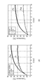
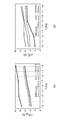
- (A) is the temperature change of the surface of the cylindrical member on the second lid portion side when the length of the tubular member on the inner space side of the cylindrical member is changed in the fluid injection type artificial muscle actuator of the present invention. It is a graph which shows the relationship between and frequency.
- (B) is a temperature change of the surface on the first lid portion side of the tubular member when the length of the tubular member on the inner space side of the tubular member is changed in the fluid injection type artificial muscle actuator of the present invention. It is a graph which shows the relationship between and frequency.
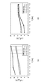
- (A) is a graph which shows the relationship between the temperature change of the surface on the 2nd cover part side of a cylindrical member, and a frequency at the time of changing the internal diameter of a tubular member in the fluid injection type artificial muscle actuator of this invention. is there.
- (B) is the graph which shows the relationship between the temperature change of the surface by the side of the 1st cover part of a cylindrical member, and a frequency at the time of changing the internal diameter of a tubular member in the fluid injection type artificial muscle actuator of this invention. is there.
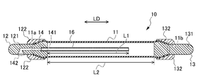
- the fluid injection type artificial muscle actuator 10 As shown in FIG. 1, the fluid injection type artificial muscle actuator 10 according to one embodiment of the present invention is formed in a cylindrical member 11, a first lid portion 12, a second lid portion 13, and a first lid portion 12.
- the 1st communicating path 14 and the tubular member 16 as an overheat suppression mechanism are provided.
- the cylindrical member 11 is configured by a member having elasticity such as rubber.
- the cylindrical member 11 has an inner diameter of 20 mm, and the cylindrical member 11 has a length L2 of 320 mm.
- the length L2 of the cylindrical member 11 refers to the length of the cylindrical member 11 that is in an extended state on the inner space side of the cylindrical member 11. That is, as shown in FIG. 1, the length of the cylindrical member 11 in the longitudinal direction LD of the cylindrical member (the air is not injected into the internal space of the fluid injection type artificial muscle actuator 10 described later) State length).
- the first lid portion 12 covers the one end portion 11 a of the cylindrical member 11.
- the first lid portion 12 includes a first lid body 121 that is inserted into one end portion 11 a of the cylindrical member 11, and a first fixing member 122 that fixes the cylindrical member 11 and the first lid body 121. .
- the second lid portion 13 closes the other end portion 11 b of the tubular member 11.
- the second lid portion 13 includes a second lid main body 131 inserted into the other end portion 11b of the cylindrical member 11, and a second fixing member 132 that fixes the cylindrical member 11 and the second lid main body 131.
- the first communication path 14 communicates the internal space and the external space of the tubular member 11.
- the first communication passage 14 is formed in the first lid main body 121, one end portion 141 opens to the internal space side of the fluid injection type artificial muscle actuator 10, and the other end portion 142 opens to the external space side. is doing.
- the tubular member 16 is disposed in the internal space of the tubular member 11 along the longitudinal direction LD of the tubular member 11.
- One end side of the tubular member 16 is connected to an end portion 141 on the inner space side of the first communication path 14.
- the tubular member 16 functions as an overheat suppression mechanism that suppresses overheating of the fluid injection type artificial muscle actuator 10. Details of the overheat suppression mechanism will be described later.
- the length L1 of the tubular member 16 is 240 mm.
- the length L1 of the tubular member 16 refers to the length of the tubular member 16 on the inner space side of the tubular member 11. That is, as shown in FIG. 1, it refers to the length of the portion exposed to the inner space side of the tubular member 16 in the longitudinal direction LD of the tubular member.
- the length L1 of the tubular member 16 on the inner space side of the tubular member 11 is 240 mm, and the length L2 of the tubular member 11 on the inner space side of the tubular member 11 is 320 mm. That is, the length L1 of the tubular member 16 on the inner space side of the tubular member 11 is 75% of the length L2 of the tubular member 11 on the inner space side of the tubular member 11.
- the length L1 of the tubular member 16 is preferably 50% or more, more preferably 60% or more of the length L2 of the tubular member 11 from the viewpoint of effectively suppressing overheating of the fluid injection type artificial muscle actuator 10. % Or more is more preferable, and 80% or more is most preferable.
- the inner diameter of the tubular member 16 is set to 6.0 mm.
- the direction of the hole of the tubular member 16 was comprised so that it might become a linear shape in the direction in alignment with the longitudinal direction LD of the cylindrical member 11, as shown in FIG.
- the tubular member 16 is made of a flexible material. More specifically, in the present embodiment, the tubular member 16 is made of nylon.
- the usage method of the fluid injection type artificial muscle actuator 10 of 1st embodiment is demonstrated.
- gas is used as the fluid.
- air is used.
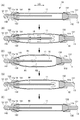
- FIG. 2A air is injected into the fluid injection type artificial muscle actuator 10 from the end 142 on the outer space side of the first communication path 14.
- the injected air passes through the tubular member 16 from the first communication passage 14 and is introduced into the internal space of the tubular member 11 from the tip of the tubular member 16 (see the arrow in FIG. 2B).
- the cylindrical member 11 begins to shrink along the longitudinal direction LD while expanding in a radial direction.
- the air inside the fluid injection type artificial muscle actuator 10 starts to be extracted from the end 142 on the outer space side of the first communication path 14, the air filled in the inner space of the tubular member 11 becomes the tubular member 16. From the front end of the gas to the outside space through the tubular member 16 and the first communication passage 14 (see FIG. 2D). And as shown to (D) of FIG. 2, the cylindrical member 11 begins to extend along the longitudinal direction LD while shrinking
- the tubular member 16 is disposed in the internal space of the tubular member 11.
- an air flow is generated in the internal space of the cylindrical member 11 as shown in FIGS. 2 (B) and 2 (D). Therefore, when the expansion / contraction (in / out of air) of the fluid injection type artificial muscle actuator 10 is repeated, it is possible to prevent local accumulation of air in the internal space of the cylindrical member 11. Partial overheating can be suppressed.
- the air temperature in the outer region R ⁇ b> 1 of the tubular member 16 is increased by repeatedly taking air into and out of the inner space of the tubular member 11. Even if the temperature of the air in the inner region R2 of the tubular member 16 becomes higher, heat exchange is performed between the air in the outer region R1 of the tubular member 16 and the air in the inner region R2 of the tubular member 16 via the tubular member 16. Done. Thereby, the overheating of the fluid injection type artificial muscle actuator 10 can be further suppressed.
- the tubular member 16 functions as an overheat suppression mechanism that suppresses overheating of the fluid injection type artificial muscle actuator 10.
- the fluid injection type artificial muscle actuator 10 according to the first embodiment described above has the following effects.
- the fluid injection type artificial muscle actuator 10 includes an overheat suppression mechanism. Thereby, it can prevent that the cylindrical member 11 overheats with taking in / out of air.
- the overheat suppression mechanism is constituted by the tubular member 16, and the tubular member 16 is arranged in the internal space of the tubular member 11.
- the length L1 of the tubular member 16 on the inner space side of the tubular member 11 is configured to be 50% or more of the length L2 of the tubular member 11 on the inner space side of the tubular member 11.
- the tubular member 16 is made of a flexible material. Thereby, even if the tubular member 16 contacts the second lid portion 13 when the tubular member 11 is contracted, the tubular member 16 is flexibly bent, so that the tubular member 11 is not inhibited from contracting.
- the fluid injection type artificial muscle actuator 10A of the second embodiment is different from the first embodiment in the configuration of the overheat suppression mechanism.
- the fluid injection type artificial muscle actuator 10 ⁇ / b> A of the second embodiment includes a second communication path 15 that is formed in the second lid portion 13 and communicates the internal space and the external space of the cylindrical member 11. .
- the overheat suppression mechanism includes the first communication path 14 and the second communication path 15 (details will be described later).
- the second communication passage 15 is formed in the second lid body 131, the end 151 opens to the internal space side of the fluid injection type artificial muscle actuator 10A, and the other end 152 extends to the external space side. It is open.
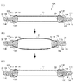
- FIG. 4A air is injected into the fluid injection type artificial muscle actuator 10 ⁇ / b> A from the outer space side end 142 of the first communication path 14. Then, the injected air is introduced from the first communication path 14 into the internal space of the cylindrical member 11. As shown in FIG. 4B, the cylindrical member 11 expands in the radial direction and contracts along the longitudinal direction LD.
- the air injection side and the discharge side are alternately changed, so that the internal space of the tubular member 11 is locally changed. Air can be prevented from staying in the air.
- the expansion / contraction (in / out of air) of the fluid injection type artificial muscle actuator 10A is repeated, it is possible to suppress the fluid injection type artificial muscle actuator 10 from being partially overheated. That is, in the second embodiment, the first communication path 14 and the second communication path 15 that take in and out air function as an overheat suppression mechanism.
- the overheat suppression mechanism is configured by the first communication path 14 and the second communication path 15.
- the length L1 of the tubular member 16 on the inner space side of the tubular member 11 is configured as 75% of the length L2 of the tubular member 11 on the inner space side of the tubular member 11. Not limited to this. That is, the length L1 of the tubular member 16 on the inner space side of the tubular member 11 is not particularly limited, but is 20% or more of the length of the tubular member 11 on the inner space side of the tubular member 11 (specifically, 50% or more, 60% or more, 70% or more, 80% or more, 90% or more, etc.). The length L1 of the tubular member 16 is preferably longer because the fluid can be diffused more strongly.
- the one end side of the tubular member 16 is configured to be connected to the end portion 141 on the inner space side of the first communication path 14, but is not limited thereto. That is, the one end side of the tubular member 16 may be configured to be connected to any portion as long as it is the first communication path 14.
- the tubular member 16 is made of a flexible material, but is not limited thereto. That is, the tubular member 16 may be made of metal. Accordingly, in the internal space of the tubular member 11, heat exchange between the air flowing through the outer region R1 of the tubular member 16 and the air flowing through the inner region R2 of the tubular member 16 can be performed efficiently, so that fluid injection It can suppress more effectively that a type artificial muscle actuator is partially overheated.
- the direction of the hole of the tubular member 16 is configured to be along the longitudinal direction LD of the tubular member 11 as shown in FIG. 1, but is not limited thereto. That is, the hole of the tubular member may be provided in a direction orthogonal to the longitudinal direction LD of the tubular member. As a result, the injected fluid diffuses inside the fluid injection type artificial muscle actuator, and the retention of the fluid can be suppressed.
- a plurality of holes in the tubular member 16 may be provided.
- the tubular member 16 is configured to be linear in the direction along the longitudinal direction LD of the tubular member 11 as shown in FIG. 1, but is not limited thereto. That is, the tubular member 16 may have at least part of a curved portion in a direction along the longitudinal direction LD of the tubular member 11.
- the surface area of the tubular member 16 increases, heat exchange between the air flowing through the outer region R1 of the tubular member 16 and the air flowing through the inner region R2 of the tubular member 16 can be performed efficiently. It can suppress more effectively that an injection type artificial muscle actuator is partially overheated.
- the inner diameter of the tubular member 16 is set to 6.0 mm, but the present invention is not limited to this. That is, it can be appropriately set according to the inner diameter of the cylindrical member 11. However, if the inner diameter of the tubular member 16 is too small, resistance when the fluid flows through the tubular member increases, and the fluid does not flow easily. Therefore, it is preferable that the tubular member 16 has a larger inner diameter. Specifically, it is preferably 4.0 mm or more, more preferably 5.0 mm or more, and most preferably 6.0 mm or more. From another viewpoint, if the inner diameter of the tubular member 16 is too large, the flow of fluid in the tubular member becomes weak, the fluid is difficult to diffuse, and the retention of the fluid is difficult to prevent.
- the inner diameter of the tubular member 16 is 7.0 mm or less.
- 6.0 mm or less is more preferable, and 5.0 mm or less is most preferable.
- the inner diameter of the cylindrical member 11 is 20 mm, it is not limited to this. That is, the inner diameter of the cylindrical member 11 may be set as appropriate according to the application and purpose of the fluid injection type artificial muscle actuator. For example, it may be 10 mm or more, 15 mm or more, 20 mm or more, or 40 mm or less, 35 mm or less, 30 mm or less, or the like. In the first embodiment, it may be set appropriately according to the inner diameter of the tubular member 16.
- the material of the first lid portion 12 and the second lid portion 13 is not particularly limited, and a conventionally known material can be used.
- a metal, a resin, or the like can be used.
- the present invention includes a manipulator including the fluid injection type artificial muscle actuator described above.
- the fluid injection type artificial muscle actuator of the present invention As described above, according to the fluid injection type artificial muscle actuator of the present invention, overheating can be suppressed. As a result, deterioration due to overheating of the fluid injection type artificial muscle actuator can be suppressed, so that it can be used continuously. Therefore, the manipulator provided with the fluid injection type artificial muscle actuator of the present invention can be continuously driven.
- the use of the manipulator is not particularly limited, but can be used for industrial use, medical use, nursing care use and the like.
- the fluid injection type artificial muscle actuator of the present invention since overheating can be suppressed, the fluid injection type artificial muscle actuator for medical use, nursing care, etc. that touches the human body during its use. It is particularly useful in that it can be used.
- Test Example 1 With respect to the fluid injection type artificial muscle actuator of the first embodiment shown in FIG. 1, an experiment was conducted as to whether or not internal overheating could be suppressed by repeatedly contracting and expanding. For comparison, the fluid injection type artificial muscle actuator of the first embodiment except for the tubular member was used. The conditions were a room temperature of 24 ° C., a driving cycle of air being taken in and out at a frequency of once every 2 seconds, and this was carried out for 10 minutes. The results are shown in Table 1.
- the inner diameter of the tubular member is 10 mm
- the inner diameter of the tubular member is 6 mm
- the length of the tubular member on the inner space side of the tubular member is 224 mm
- the length of the tubular member on the inner space side of the tubular member is 168 mm (the length of the tubular member on the inner space side of the tubular member is 75% of the length of the tubular member on the inner space side of the tubular member), and the material of the first lid portion and the second lid portion Made of metal.
- the fluid injection type artificial muscle actuator is provided with a tubular member, so that overheating of the surface on the second lid portion side of the tubular member is suppressed as compared with the case where the tubular member is not used. It was confirmed that Further, the temperature of the surface of the cylindrical member on the second lid portion side, the temperature of the surface of the first lid portion side, and the temperature of the surface of the first lid portion are all suppressed to a temperature of room temperature or about body temperature. confirmed. Thus, it was suggested that the provision of the tubular member suppresses the temperature of the fluid injection type artificial muscle actuator to a temperature at which there is no problem even if it touches the human body.
- FIGS. 5 to 9 show the results obtained without the tubular member, and (B) shows the results obtained with the tubular member (the fluid injection type artificial muscle actuator of the first embodiment).
- FIG. 5 shows the drive cycle once every 4 seconds
- FIG. 6 shows 3 times every 8 seconds
- FIG. 7 shows 11 times every 24 seconds
- FIG. 8 shows once every 2 seconds
- FIG. 9 shows 5 times every 9 seconds. The frequency of times.
- Theta IN is the first cover side of the cylindrical member
- theta END means the temperature of the surface of each of the second lid portion side of the cylindrical member.
- D means the inner diameter of the tubular member
- L means the length of the tubular member on the inner space side of the tubular member
- f means frequency
- A means voltage.
- the inner diameter of the tubular member is 20 mm
- the inner diameter of the tubular member is 6 mm
- the length of the tubular member on the inner space side of the tubular member is 320 mm
- the length of the tubular member on the inner space side of the tubular member is 240 mm (the length of the tubular member on the inner space side of the tubular member is 75% of the length of the tubular member on the inner space side of the tubular member)
- the material of the first lid portion and the second lid portion is resin Consists of.
- the fluid injection type artificial muscle actuator of the first embodiment used in Test Example 1 changes the length of the tubular member on the inner space side of the tubular member (specifically, the length is 80.0 mm, 120 0.05mm, 160.0mm and those without a tubular member were prepared), the frequency at the time of contraction and expansion was changed, and contraction and expansion were performed for 10 minutes, and the first lid part side or the second lid part The change in temperature of the side surface was evaluated.
- the inner diameter of the tubular member is also changed to “5.0 mm”, and the length of the tubular member on the inner space side of the tubular member is changed.
- the length of the tubular member on the inner space side of the tubular member is 80.0 mm, and the length is 25% of the length of the tubular member on the inner space side of the tubular member.
- the length of the tubular member on the inner space side of the tubular member is 120.0 mm, the length is 38% of the length of the tubular member on the inner space side of the tubular member,
- the length of the tubular member on the inner space side of 120.0 mm is 50% of the length of the tubular member on the inner space side of the tubular member).
- (A) shows the graph regarding the temperature change of the surface by the side of the 2nd cover part of a cylindrical member
- (B) is a graph regarding the temperature change of the surface by the side of the 1st cover part of a cylindrical member.
- “Lp” indicates the length of each tubular member
- “empty” indicates that the tubular member is not provided.
- the tubular member is not overheated on the surface on the second lid portion side of the tubular member even if the frequency of contraction and expansion is changed. It was confirmed that it was suppressed compared with. In particular, it was confirmed that as the length of the tubular member on the inner space side of the tubular member becomes longer, overheating of the surface of the tubular member on the second lid side is suppressed.
- Test Example 4 The fluid-injected artificial muscle actuator of the first embodiment used in Test Example 1 changes the length of the tubular member on the inner space side of the tubular member (specifically, the length is 80.0 mm) And a tube not provided with a tubular member), changing the frequency at the time of contraction and expansion, performing contraction and expansion for 10 minutes, and changing the temperature of the surface on the first lid part side or the second lid part side evaluated.
- a tubular member having an inner diameter of “5.0 mm” and a “6.0 mm” were prepared and evaluated.
- the length of the tubular member on the inner space side of the tubular member was changed to 319 mm as in Test Example 3 (that is, the length of the tubular member on the inner space side of the tubular member was 80.0 mm) The length is 25% of the length of the cylindrical member on the inner space side of the cylindrical member).
- the evaluation results are shown in FIG. In FIG. 11, (A) shows the graph regarding the temperature change of the surface by the side of the 2nd cover part of a cylindrical member, (B) is the graph regarding the temperature change of the surface by the side of the 1st cover part of a cylindrical member. .
- “Di” indicates the inner diameter of each tubular member, and “empty” indicates that the tubular member is not provided.
- Table 2 below shows the relationship between vibration and contraction frequencies and energy consumption for each sample.
- “Regular” in Table 2 below indicates a device without a tubular member.
- the tubular member is not used due to overheating of the surface on the second lid portion side of the tubular member even if the frequency of contraction and expansion is changed. It was confirmed that the amount of energy consumption was also suppressed. In particular, it was confirmed that the tubular member having a smaller inner diameter suppresses overheating of the surface of the tubular member on the second lid portion side, and also suppresses energy consumption.
Landscapes
- Engineering & Computer Science (AREA)
- Mechanical Engineering (AREA)
- Physics & Mathematics (AREA)
- Fluid Mechanics (AREA)
- General Engineering & Computer Science (AREA)
- Chemical & Material Sciences (AREA)
- Analytical Chemistry (AREA)
- Robotics (AREA)
- Prostheses (AREA)
- Actuator (AREA)
Abstract
流体の出し入れに伴って生じる過熱を抑制することができる流体注入型人工筋アクチュエータを提供する。 流体注入型人工筋アクチュエータ(10)は、弾性を有する筒状部材(11)と、筒状部材(11)の一端部をふさぐ第1蓋部(12)と、筒状部材(11)の他端部をふさぐ第2蓋部(13)と、第1蓋部(12)に形成され筒状部材(11)の内部空間と外部空間とを連通させる第1連通路(14)と、流体の出し入れに伴って生じる過熱を抑制する過熱抑制機構としての管状部材(16)を備える。
Description
本発明は、流体注入型人工筋アクチュエータ及びマニピュレータに関する。
人工筋アクチュエータは、圧縮空気によって人間の筋肉のように収縮するアクチュエータであり、軽量で高出力であるため、医療用、工業用等の様々な用途で広く用いられている。
例えば、特許文献1には、人工筋アクチュエータ内部に抵抗体を備えた、高精度な制御を可能とする人工筋アクチュエータが開示されている。
しかしながら、従来の人工筋アクチュエータは、空気の圧縮を繰り返すことで、空気流入側と反対側の端部が高温になるものであり、人工筋の寿命を縮めることから、連続駆動に制限があった。また。高温となるため、介護用ロボット用等、人体に接触する可能性がある用途には使用することが難しかった。
本発明は、以上の実情に鑑みてなされたものであり、流体の出し入れに伴って生じる過熱を抑制することができる流体注入型人工筋アクチュエータを提供することを目的とする。
本発明者らは、流体の出し入れに伴って生じる過熱を抑制する過熱抑制機構を備えることによって、流体注入型人工筋アクチュエータの温度上昇を抑制することができることを見出し、本発明を完成するに至った。より具体的には、本発明は以下のようなものを提供する。
(1)弾性を有する筒状部材と、前記筒状部材の一端部をふさぐ第1蓋部と、前記筒状部材の他端部をふさぐ第2蓋部と、前記第1蓋部に形成され前記筒状部材の内部空間と外部空間とを連通させる第1連通路と、を備え、前記筒状部材の内部に流体を出し入れすることにより伸縮する流体注入型人工筋アクチュエータであって、前記流体の出し入れに伴って生じる過熱を抑制する過熱抑制機構を更に備える流体注入型人工筋アクチュエータ。
(2)前記過熱抑制機構は、前記筒状部材の内部空間における流体の滞留を抑制する機構である(1)に記載の流体注入型人工筋アクチュエータ。
(3)前記過熱抑制機構は、前記筒状部材の内部空間に、該筒状部材の長手方向に沿うように配置され、一端側が前記第1連通路に接続される管状部材を備える(1)又は(2)に記載の流体注入型人工筋アクチュエータ。
(4)前記筒状部材の内部空間側における前記管状部材の長さは、前記筒状部材の内部空間側における伸びた状態である前記筒状部材の長さの50%以上である(3)に記載の流体注入型人工筋アクチュエータ。
(5)前記管状部材は、可撓性を有する材料で構成される(3)又は(4)に記載の流体注入型人工筋アクチュエータ。
(6)前記第2蓋部に形成され前記筒状部材の内部空間と外部空間とを連通させる第2連通路を更に備え、
前記過熱抑制機構は、前記第1連通路及び前記第2連通路により構成される(1)又は(2)に記載の流体注入型人工筋アクチュエータ。
前記過熱抑制機構は、前記第1連通路及び前記第2連通路により構成される(1)又は(2)に記載の流体注入型人工筋アクチュエータ。
(7)(1)から(6)いずれかに記載の流体注入型人工筋アクチュエータを備えるマニピュレータ。
本発明によれば、流体注入型人工筋アクチュエータの過熱を抑制することができる。
以下、本発明の流体注入型人工筋アクチュエータの好ましい一実施形態について図面を参照しながら説明する。
本発明の一実施形態の流体注入型人工筋アクチュエータ10は、図1に示すように、筒状部材11と、第1蓋部12と、第2蓋部13と、第1蓋部12に形成される第1連通路14と、過熱抑制機構としての管状部材16と、を備える。
本発明の一実施形態の流体注入型人工筋アクチュエータ10は、図1に示すように、筒状部材11と、第1蓋部12と、第2蓋部13と、第1蓋部12に形成される第1連通路14と、過熱抑制機構としての管状部材16と、を備える。
筒状部材11は、ゴム等の弾性を有する部材により構成される。本実施形態では、筒状部材11の内径を20mmとし、筒状部材11の長さL2を320mmとして構成した。筒状部材11の長さL2とは、筒状部材11の内部空間側における伸びた状態である筒状部材11の長さをいう。即ち、図1に示すように、筒状部材の長手方向LDにおける、筒状部材11が伸びた状態の長さ(後述する、空気が流体注入型人工筋アクチュエータ10の内部空間に注入されていない状態の長さ)をいう。
第1蓋部12は、筒状部材11の一端部11aをふさぐ。この第1蓋部12は、筒状部材11の一端部11aに挿入される第1蓋本体121と、筒状部材11と第1蓋本体121とを固定する第1固定部材122と、を備える。
第2蓋部13は、筒状部材11の他端部11bをふさぐ。この第2蓋部13は、筒状部材11の他端部11bに挿入される第2蓋本体131と、筒状部材11と第2蓋本体131とを固定する第2固定部材132と、を備える。
第1連通路14は、筒状部材11の内部空間と外部空間とを連通させる。本実施形態では、第1連通路14は、第1蓋本体121に形成され、一端部141が流体注入型人工筋アクチュエータ10の内部空間側に開口し、他端部142が外部空間側に開口している。
第1蓋部12は、筒状部材11の一端部11aをふさぐ。この第1蓋部12は、筒状部材11の一端部11aに挿入される第1蓋本体121と、筒状部材11と第1蓋本体121とを固定する第1固定部材122と、を備える。
第2蓋部13は、筒状部材11の他端部11bをふさぐ。この第2蓋部13は、筒状部材11の他端部11bに挿入される第2蓋本体131と、筒状部材11と第2蓋本体131とを固定する第2固定部材132と、を備える。
第1連通路14は、筒状部材11の内部空間と外部空間とを連通させる。本実施形態では、第1連通路14は、第1蓋本体121に形成され、一端部141が流体注入型人工筋アクチュエータ10の内部空間側に開口し、他端部142が外部空間側に開口している。
管状部材16は、図1に示すように、筒状部材11の内部空間に、筒状部材11の長手方向LDに沿うように配置される。この管状部材16の一端側は、第1連通路14の内部空間側の端部141に接続される。
管状部材16は、流体注入型人工筋アクチュエータ10の過熱を抑制する過熱抑制機構として機能する。過熱抑制機構の詳細については、後述する。
管状部材16は、流体注入型人工筋アクチュエータ10の過熱を抑制する過熱抑制機構として機能する。過熱抑制機構の詳細については、後述する。
本実施形態では、管状部材16の長さL1を、240mmとして構成した。管状部材16の長さL1は、筒状部材11の内部空間側における管状部材16の長さをいう。即ち、図1に示すように、筒状部材の長手方向LDにおける、管状部材16の内部空間側に露出した部分の長さをいう。
前述のとおり、筒状部材11の内部空間側における管状部材16の長さL1は、240mmであり、筒状部材11の内部空間側における筒状部材11の長さL2は320mmである。即ち、筒状部材11の内部空間側における管状部材16の長さL1は、筒状部材11の内部空間側における筒状部材11の長さL2の75%である。
管状部材16の長さL1は、流体注入型人工筋アクチュエータ10の過熱を効果的に抑制する観点から、筒状部材11の長さL2の50%以上が好ましく、60%以上がより好ましく、70%以上が更に好ましく、80%以上が最も好ましい。
管状部材16の長さL1は、流体注入型人工筋アクチュエータ10の過熱を効果的に抑制する観点から、筒状部材11の長さL2の50%以上が好ましく、60%以上がより好ましく、70%以上が更に好ましく、80%以上が最も好ましい。
本実施形態では、管状部材16の内径を6.0mmとして構成した。また、管状部材16の孔の向きは、図1に示すように、筒状部材11の長手方向LDに沿う向きに、直線形状となるように構成した。
管状部材16は、可撓性を有する材料で構成される。より具体的には、本実施形態では、管状部材16はナイロンにより構成される。
次に、第一実施形態の流体注入型人工筋アクチュエータ10の使用方法について説明する。尚、流体としては、気体を用いる。本実施形態では空気を用いる。
まず、図2の(A)に示すように、流体注入型人工筋アクチュエータ10の内部に、第1連通路14の外部空間側の端部142から空気を注入する。すると、注入された空気は、第1連通路14から管状部材16をとおり、この管状部材16の先端から筒状部材11の内部空間に導入される(図2(B)の矢印参照)。そして、図2の(B)に示すように、筒状部材11は、径方向に膨らむと共に長手方向LDに沿うように縮み始める。
まず、図2の(A)に示すように、流体注入型人工筋アクチュエータ10の内部に、第1連通路14の外部空間側の端部142から空気を注入する。すると、注入された空気は、第1連通路14から管状部材16をとおり、この管状部材16の先端から筒状部材11の内部空間に導入される(図2(B)の矢印参照)。そして、図2の(B)に示すように、筒状部材11は、径方向に膨らむと共に長手方向LDに沿うように縮み始める。
流体注入型人工筋アクチュエータ10の内部に流体を注入し終わると、図2の(C)に示すように、筒状部材11は縮んだ状態となる。
次に、第1連通路14の外部空間側の端部142から流体注入型人工筋アクチュエータ10の内部の空気を抜き始めると、筒状部材11の内部空間に充填された空気は、管状部材16の先端から管状部材16及び第1連通路14を通って外部空間に放出される(図2(D)参照)。そして、図2の(D)に示すように、筒状部材11は、径方向に縮むと共に長手方向LDに沿うように伸び始める。そして、流体注入型人工筋アクチュエータ10から空気が抜けきると、図2の(E)に示すように、筒状部材11は空気導入前の長さまで伸びる。第一実施形態においては、このように、筒状部材11の内部に空気を出し入れすることにより、流体注入型人工筋アクチュエータ10は伸縮する。
ここで、管状部材16を含まずに流体注入型人工筋アクチュエータを構成した場合、筒状部材11の内部空間に繰り返し空気の出し入れを行うと、筒状部材11の他端部11b側において空気の流動性が悪くなり空気が滞留する。すると、空気の圧縮に伴い発生する熱により、筒状部材11の他端部11b側が過熱されてしまう。そこで、第一実施形態では、筒状部材11の内部空間に管状部材16を配置した。これにより、筒状部材11の内部に空気を出し入れする場合に、図2(B)及び図2(D)に示すように、筒状部材11の内部空間に空気の流れを生じさせられる。よって、流体注入型人工筋アクチュエータ10の伸縮(空気の出し入れ)を繰り返した場合に、筒状部材11の内部空間に局所的に空気が滞留することを防げるので、流体注入型人工筋アクチュエータ10が部分的に過熱することを抑制できる。
また、管状部材16を含んで流体注入型人工筋アクチュエータを構成した場合において、筒状部材11の内部空間に繰り返し空気の出し入れを行うことによって、管状部材16の外側領域R1の空気の温度が、管状部材16の内側領域R2の空気の温度より高くなったとしても、管状部材16を介して、管状部材16の外側領域R1の空気と、管状部材16の内側領域R2の空気とで熱交換が行われる。これにより、流体注入型人工筋アクチュエータ10の過熱を更に抑制できる。
このように、第一実施形態において、管状部材16は、流体注入型人工筋アクチュエータ10の過熱を抑制する過熱抑制機構として機能している。
以上説明した第一実施形態の流体注入型人工筋アクチュエータ10によれば、以下のような効果を奏する。
(1)流体注入型人工筋アクチュエータ10を、過熱抑制機構を含んで構成した。これにより、空気の出し入れに伴って筒状部材11が過熱することを防げる。
(2)過熱抑制機構を、管状部材16により構成し、この管状部材16を筒状部材11の内部空間に配置した。これにより、筒状部材11の内部に空気を出し入れする場合に、筒状部材11の内部空間に空気の流れを生じさせられる。よって、流体注入型人工筋アクチュエータ10の伸縮(空気の出し入れ)を繰り返した場合に、筒状部材11の内部空間に局所的に空気が滞留することを防げるので、流体注入型人工筋アクチュエータ10が部分的に過熱することを抑制できる。また、管状部材16を介して、管状部材16の外側領域R1の空気と、管状部材16の内側領域R2の空気とで熱交換が行われるので、流体注入型人工筋アクチュエータ10の過熱を更に抑制できる。
(3)筒状部材11の内部空間側における管状部材16の長さL1を、筒状部材11の内部空間側における筒状部材11の長さL2の50%以上に構成した。これにより、筒状部材11の内部空間に注入された空気が第2蓋部13の内部空間側にあたって拡散しやすくなるので、流体注入型人工筋アクチュエータ10の内部において空気を循環するように流せる。その結果、流体の出し入れに伴って生じる過熱をより効果的に抑制できる。
(4)管状部材16を、可撓性を有する材料により構成した。これにより、筒状部材11が縮んだ際に管状部材16が第2蓋部13に接触したとしても、管状部材16が柔軟に曲がるので、筒状部材11が縮むことを阻害しない。
次に、本発明の流体注入型人工筋アクチュエータの第二実施形態について図面を参照しながら説明する。尚、第二実施形態の説明にあたって、同一構成要件については同一符号を付し、その説明を省略もしくは簡略化する。
第二実施形態の流体注入型人工筋アクチュエータ10Aは、過熱抑制機構の構成において第一実施形態と異なる。
第二実施形態の流体注入型人工筋アクチュエータ10Aは、過熱抑制機構の構成において第一実施形態と異なる。
第二実施形態の流体注入型人工筋アクチュエータ10Aは、図3に示すように、第2蓋部13に形成され筒状部材11の内部空間と外部空間とを連通させる第2連通路15を備える。そして、第二実施形態では、過熱抑制機構は、第1連通路14と第2連通路15とにより構成される(詳細は後述する)。
第二実施形態では、第2連通路15は、第2蓋本体131に形成され、端部151が流体注入型人工筋アクチュエータ10Aの内部空間側に開口し、他端部152が外部空間側に開口している。
第二実施形態では、第2連通路15は、第2蓋本体131に形成され、端部151が流体注入型人工筋アクチュエータ10Aの内部空間側に開口し、他端部152が外部空間側に開口している。
次に、第二実施形態の流体注入型人工筋アクチュエータ10Aの使用方法について説明する。
まず、図4の(A)に示すように、流体注入型人工筋アクチュエータ10Aの内部に、第1連通路14の外部空間側の端部142から空気を注入する。すると、注入された空気は、第1連通路14から筒状部材11の内部空間に導入される。そして、図4の(B)に示すように、筒状部材11は、径方向に膨らむと共に長手方向LDに沿うように縮む。
まず、図4の(A)に示すように、流体注入型人工筋アクチュエータ10Aの内部に、第1連通路14の外部空間側の端部142から空気を注入する。すると、注入された空気は、第1連通路14から筒状部材11の内部空間に導入される。そして、図4の(B)に示すように、筒状部材11は、径方向に膨らむと共に長手方向LDに沿うように縮む。
縮んだ状態の筒状部材11を伸ばす場合には、第2連通路15から流体注入型人工筋アクチュエータ10Aの内部の空気を抜き始める。すると、筒状部材11の内部空間に充填された空気は、第1連通路14
を通って外部空間に放出される。そして、図4の(C)に示すように、筒状部材11は、径方向に縮むと共に長手方向LDに沿うように伸びる。
を通って外部空間に放出される。そして、図4の(C)に示すように、筒状部材11は、径方向に縮むと共に長手方向LDに沿うように伸びる。
次いで、再び流体注入型人工筋アクチュエータ10Aを縮ませる場合には、第2連通路15から筒状部材11の内部空間に空気を注入する。そして、縮んだ流体注入型人工筋アクチュエータ10Aを伸ばす場合には、第1連通路14から空気を放出する。
このように、第2実施形態では、流体注入型人工筋アクチュエータ10Aを繰り返し伸縮させる場合には、空気の注入側及び放出側を交互に交代させることで、筒状部材11の内部空間に局所的に空気が滞留することを防げる。その結果、流体注入型人工筋アクチュエータ10Aの伸縮(空気の出し入れ)を繰り返した場合に、流体注入型人工筋アクチュエータ10が部分的に過熱することを抑制できる。即ち、第二実施形態では、空気を出し入れする第1連通路14及び第2連通路15が過熱抑制機構として機能している。
以上説明した第二実施形態の流体注入型人工筋アクチュエータ10Aによれば、上記(1)の効果を奏する他、以下のような効果を奏する。
過熱抑制機構を、第1連通路14及び第2連通路15により構成した。これにより、流体注入型人工筋アクチュエータ10Aを繰り返し伸縮させる場合に、空気の注入側及び放出側を交互に交代させることで、筒状部材11の内部空間に局所的に空気が滞留することを防げる。その結果、流体注入型人工筋アクチュエータ10Aの伸縮(空気の出し入れ)を繰り返した場合に、流体注入型人工筋アクチュエータ10Aが部分的に過熱することを抑制できる。
以上、本発明の流体注入型人工筋アクチュエータの好ましい一実施形態につき説明したが、本発明は、上述の実施形態に制限されるものではなく、適宜変更が可能である。
例えば、第一実施形態では、筒状部材11の内部空間側における管状部材16の長さL1を、筒状部材11の内部空間側における筒状部材11の長さL2の75%として構成したが、これに限らない。即ち、筒状部材11の内部空間側における管状部材16の長さL1は、特に限定されないが、筒状部材11の内部空間側における筒状部材11の長さの20%以上(具体的には、50%以上、60%以上、70%以上、80%以上、90%以上等)等にしてもよい。管状部材16の長さL1は、より流体を強く拡散できるため、長い方が好ましい。
例えば、第一実施形態では、筒状部材11の内部空間側における管状部材16の長さL1を、筒状部材11の内部空間側における筒状部材11の長さL2の75%として構成したが、これに限らない。即ち、筒状部材11の内部空間側における管状部材16の長さL1は、特に限定されないが、筒状部材11の内部空間側における筒状部材11の長さの20%以上(具体的には、50%以上、60%以上、70%以上、80%以上、90%以上等)等にしてもよい。管状部材16の長さL1は、より流体を強く拡散できるため、長い方が好ましい。
第一実施形態では、管状部材16の一端側は、第1連通路14の内部空間側の端部141に接続して構成したが、これに限らない。即ち、管状部材16の一端側は、第1連通路14であれば、いずれの部分に接続して構成してもかまわない。
第一実施形態では、管状部材16は、可撓性を有する材料で構成したが、これに限らない。即ち、管状部材16は、金属で構成されてもよい。これにより、筒状部材11の内部空間において、管状部材16の外側領域R1を流れる空気と管状部材16の内側領域R2を流れる空気との間の熱交換を効率的に行わせられるので、流体注入型人工筋アクチュエータが部分的に過熱されることをより効果的に抑制できる。
第一実施形態では、管状部材16の孔の向きは、図1に示すように、筒状部材11の長手方向LDに沿う向きに構成したが、これに限らない。即ち、管状部材の孔を、筒状部材の長手方向LDと直交する方向に設けてもかまわない。これによって、注入された流体が、流体注入型人工筋アクチュエータの内部で拡散し、流体の滞留を抑制することができる。また、管状部材16の孔は複数設けてもよい。
第一実施形態では、管状部材16は、図1に示すように、筒状部材11の長手方向LDに沿う向きに、直線形状となるように構成したが、これに限らない。即ち、管状部材16には、筒状部材11の長手方向LDに沿う向きに、曲線形状部分が少なくとも一部にあってもよい。これにより、管状部材16の表面積が大きくなるので、管状部材16の外側領域R1を流れる空気と管状部材16の内側領域R2を流れる空気との間の熱交換を効率的に行わせられるので、流体注入型人工筋アクチュエータが部分的に過熱されることをより効果的に抑制できる。
第一実施形態では、管状部材16の内径を6.0mmとして構成したが、これに限らない。即ち、筒状部材11の内径に合わせて適宜設定することができる。ただし、管状部材16の内径は、小さすぎると、流体が管状部材内を流れる際の抵抗が大きくなり、流体が流れにくくなる。よって、管状部材16の内径は大きい方が好ましい。具体的には、4.0mm以上が好ましく、5.0mm以上がより好ましく、6.0mm以上が最も好ましい。別の観点で、管状部材16の内径が大きすぎると、流体の筒状部材内の流れが弱くなり、流体が拡散しにくくなり、流体の滞留を防ぎにくくなる。そのため、15.0mm以下が好ましく、12.0mm以下がより好ましく、10.0mm以下が最も好ましい。また、別の観点で、管状部材16の内径が小さくなると、筒状部材の膨張、収縮に使用されるエネルギー消費量も抑制しやすくなることから、管状部材16の内径は、7.0mm以下が好ましく、6.0mm以下がより好ましく、5.0mm以下が最も好ましい。
筒状部材11の内径を、20mmとして構成したが、これに限らない。即ち、筒状部材11の内径は、流体注入型人工筋アクチュエータの用途や目的に応じて適宜設定してもよい。例えば、10mm以上、15mm以上、20mm以上等にしてもよく、40mm以下、35mm以下、30mm以下等にしてもよい。また、第一実施形態では、管状部材16の内径に合わせて適宜設定してもよい。
第1蓋部12、第2蓋部13の材質は、特に限定されず、従来の公知の材質を使用することができ、例えば、金属、樹脂等を使用することができる。
本発明では、以上に述べた流体注入型人工筋アクチュエータを備えるマニピュレータを包含する。
前述のとおり、本発明の流体注入型人工筋アクチュエータによれば、過熱を抑制することができる。その結果、流体注入型人工筋アクチュエータの過熱による劣化を抑制できるので、連続して使用することができる。そのため、本発明の流体注入型人工筋アクチュエータを備えるマニピュレータは、連続した駆動が可能である。
マニピュレータの用途は、特に限定されないが、工業用、医療用、介護用等に用いることができる。本発明の流体注入型人工筋アクチュエータによれば、過熱を抑制することができるので、医療用、介護用等の、流体注入型人工筋アクチュエータがその使用の際に人体に触れてしまうものについても使用することができるという点で特に有用である。
(試験例1)
図1に示す、第一実施形態の流体注入型人口筋アクチュエータについて、収縮、膨張を繰り返し、内部の過熱を抑制できるか否かについて実験を行った。比較として、第一実施形態の流体注入型人口筋アクチュエータから管状部材を除いたものを用いた。条件は、室温24℃にて、駆動周期は2秒に1回の頻度で空気の出し入れを行い、これを10分間行った。その結果を表1に示す。なお、本実験では、筒状部材の内径を10mm、管状部材の内径を6mm、筒状部材の内部空間側における筒状部材の長さを224mm、筒状部材の内部空間側における管状部材の長さを168mmとし(筒状部材の内部空間側における管状部材の長さが、筒状部材の内部空間側における筒状部材の長さの75%)、第1蓋部及び第2蓋部の材質を金属で構成した。
図1に示す、第一実施形態の流体注入型人口筋アクチュエータについて、収縮、膨張を繰り返し、内部の過熱を抑制できるか否かについて実験を行った。比較として、第一実施形態の流体注入型人口筋アクチュエータから管状部材を除いたものを用いた。条件は、室温24℃にて、駆動周期は2秒に1回の頻度で空気の出し入れを行い、これを10分間行った。その結果を表1に示す。なお、本実験では、筒状部材の内径を10mm、管状部材の内径を6mm、筒状部材の内部空間側における筒状部材の長さを224mm、筒状部材の内部空間側における管状部材の長さを168mmとし(筒状部材の内部空間側における管状部材の長さが、筒状部材の内部空間側における筒状部材の長さの75%)、第1蓋部及び第2蓋部の材質を金属で構成した。

表1に示すように、流体注入型人口筋アクチュエータは、管状部材を備えることで筒状部材の第2蓋部側の表面の過熱が、管状部材を使用していないものと比較して抑制されることが確認された。また、筒状部材の第2蓋部側の表面の温度、第1蓋部側の表面の温度、第1蓋部の表面の温度の全てが、室温又は体温程度の温度に抑制されたことが確認された。これにより、管状部材を備えることで、流体注入型人口筋アクチュエータの温度が人体に触れても問題ない程度の温度に抑制されることが示唆された。
(試験例2)
上記試験例1から、空気の出し入れに使用する電圧、周波数を変更して、流体注入型人口筋アクチュエータの収縮、膨張の繰り返しの実験を行った。その結果を図5~9に示す。図5~9中、(A)は管状部材なし、(B)は管状部材ありのもの(第一実施形態の流体注入型人口筋アクチュエータ)による結果を示す。駆動周期は、図5は、4秒に1回は、図6は8秒に3回は、図7は24秒に11回、図8は2秒に1回、図9は9秒に5回の頻度である。「θIN」は筒状部材の第1蓋部側の、「θEND」は筒状部材の第2蓋部側のそれぞれの表面の温度を意味する。「D」は管状部材の内径、「L」は筒状部材の内部空間側における管状部材の長さ、「f」は周波数、「A」は電圧を意味する。本実験では、筒状部材の内径を20mm、管状部材の内径を6mm、筒状部材の内部空間側における筒状部材の長さを320mm、筒状部材の内部空間側における管状部材の長さを240mmとし(筒状部材の内部空間側における管状部材の長さが、筒状部材の内部空間側における筒状部材の長さの75%)、第1蓋部及び第2蓋部の材質を樹脂で構成した。
上記試験例1から、空気の出し入れに使用する電圧、周波数を変更して、流体注入型人口筋アクチュエータの収縮、膨張の繰り返しの実験を行った。その結果を図5~9に示す。図5~9中、(A)は管状部材なし、(B)は管状部材ありのもの(第一実施形態の流体注入型人口筋アクチュエータ)による結果を示す。駆動周期は、図5は、4秒に1回は、図6は8秒に3回は、図7は24秒に11回、図8は2秒に1回、図9は9秒に5回の頻度である。「θIN」は筒状部材の第1蓋部側の、「θEND」は筒状部材の第2蓋部側のそれぞれの表面の温度を意味する。「D」は管状部材の内径、「L」は筒状部材の内部空間側における管状部材の長さ、「f」は周波数、「A」は電圧を意味する。本実験では、筒状部材の内径を20mm、管状部材の内径を6mm、筒状部材の内部空間側における筒状部材の長さを320mm、筒状部材の内部空間側における管状部材の長さを240mmとし(筒状部材の内部空間側における管状部材の長さが、筒状部材の内部空間側における筒状部材の長さの75%)、第1蓋部及び第2蓋部の材質を樹脂で構成した。
図5~9に示すとおり、電圧や周波数を変更することによって、空気の出し入れする速さを変更しても、「θIN」の温度の過熱が抑制されたことが確認され、「θEND」の温度が体温に触れても問題ない程度の温度に抑制されたことが確認された。
以上の結果は、管状部材の外側領域の空気と管状部材の内側領域の空気とが熱交換されたこと、及び、内部空間に注入された空気が第2蓋部の内部空間側にあたって拡散し、その内部の空気が循環し、空気の滞留が抑制されたことに起因すると考えられる。
(試験例3)
試験例1で用いた第一実施形態の流体注入型人口筋アクチュエータとは、筒状部材の内部空間側における管状部材の長さを変更し(具体的には、長さが80.0mm、120.0mm、160.0mmのものと、管状部材を備えないものを準備した)、収縮、膨張時の周波数も変更して、収縮、膨張を10分間行い、第1蓋部側又は第2蓋部側の表面の温度の変化を評価した。なお、試験例1で用いた第一実施形態の流体注入型人口筋アクチュエータから、管状部材の内径も「5.0mm」に変更し、筒状部材の内部空間側における筒状部材の長さを319mmに変更した(即ち、筒状部材の内部空間側における管状部材の長さが80.0mmのものは、その長さが筒状部材の内部空間側における筒状部材の長さの25%であり、筒状部材の内部空間側における管状部材の長さが120.0mmのものは、その長さが筒状部材の内部空間側における筒状部材の長さの38%であり、筒状部材の内部空間側における管状部材の長さが120.0mmのものは、その長さが筒状部材の内部空間側における筒状部材の長さの50%である)。その評価結果を図10に示す。図10中、(A)は、筒状部材の第2蓋部側の表面の温度変化に関するグラフを示し、(B)は筒状部材の第1蓋部側の表面の温度変化に関するグラフである。また、図10中、「Lp」は、それぞれの管状部材の長さを示し、「empty」は、管状部材を備えないものを示す。
試験例1で用いた第一実施形態の流体注入型人口筋アクチュエータとは、筒状部材の内部空間側における管状部材の長さを変更し(具体的には、長さが80.0mm、120.0mm、160.0mmのものと、管状部材を備えないものを準備した)、収縮、膨張時の周波数も変更して、収縮、膨張を10分間行い、第1蓋部側又は第2蓋部側の表面の温度の変化を評価した。なお、試験例1で用いた第一実施形態の流体注入型人口筋アクチュエータから、管状部材の内径も「5.0mm」に変更し、筒状部材の内部空間側における筒状部材の長さを319mmに変更した(即ち、筒状部材の内部空間側における管状部材の長さが80.0mmのものは、その長さが筒状部材の内部空間側における筒状部材の長さの25%であり、筒状部材の内部空間側における管状部材の長さが120.0mmのものは、その長さが筒状部材の内部空間側における筒状部材の長さの38%であり、筒状部材の内部空間側における管状部材の長さが120.0mmのものは、その長さが筒状部材の内部空間側における筒状部材の長さの50%である)。その評価結果を図10に示す。図10中、(A)は、筒状部材の第2蓋部側の表面の温度変化に関するグラフを示し、(B)は筒状部材の第1蓋部側の表面の温度変化に関するグラフである。また、図10中、「Lp」は、それぞれの管状部材の長さを示し、「empty」は、管状部材を備えないものを示す。
評価の結果から、いずれの管状部材を備えたものにおいても、収縮、膨張の振動数を変化させても、筒状部材の第2蓋部側の表面の過熱が管状部材を使用していないものと比較して抑制されることが確認された。特に、筒状部材の内部空間側における管状部材の長さが長くなるほど、筒状部材の第2蓋部側の表面の過熱が抑制されることが確認された。
(試験例4)
試験例1で用いた第一実施形態の流体注入型人口筋アクチュエータとは、筒状部材の内部空間側における管状部材の長さを変更し(具体的には、長さが80.0mmのものと、管状部材を備えないものを準備した)、収縮、膨張時の周波数も変更して、収縮、膨張を10分間行い、第1蓋部側又は第2蓋部側の表面の温度の変化を評価した。また、管状部材の内径が「5.0mm」のものと、「6.0mm」のものを準備し、それぞれについて評価した。筒状部材の内部空間側における筒状部材の長さは、試験例3と同様に、319mmに変更した(即ち、筒状部材の内部空間側における管状部材の長さが80.0mmのものは、その長さが筒状部材の内部空間側における筒状部材の長さの25%である)。その評価結果を図11に示す。図11中、(A)は、筒状部材の第2蓋部側の表面の温度変化に関するグラフを示し、(B)は筒状部材の第1蓋部側の表面の温度変化に関するグラフである。図11中、「Di」は、それぞれの管状部材の内径を示し、「empty」は、管状部材を備えないものを示す。また、振動、収縮の周波数と、各サンプル毎の消費エネルギーとの関係を、以下の表2に示す。また、以下の表2の「Regular」は、管状部材を備えないものを示す。
試験例1で用いた第一実施形態の流体注入型人口筋アクチュエータとは、筒状部材の内部空間側における管状部材の長さを変更し(具体的には、長さが80.0mmのものと、管状部材を備えないものを準備した)、収縮、膨張時の周波数も変更して、収縮、膨張を10分間行い、第1蓋部側又は第2蓋部側の表面の温度の変化を評価した。また、管状部材の内径が「5.0mm」のものと、「6.0mm」のものを準備し、それぞれについて評価した。筒状部材の内部空間側における筒状部材の長さは、試験例3と同様に、319mmに変更した(即ち、筒状部材の内部空間側における管状部材の長さが80.0mmのものは、その長さが筒状部材の内部空間側における筒状部材の長さの25%である)。その評価結果を図11に示す。図11中、(A)は、筒状部材の第2蓋部側の表面の温度変化に関するグラフを示し、(B)は筒状部材の第1蓋部側の表面の温度変化に関するグラフである。図11中、「Di」は、それぞれの管状部材の内径を示し、「empty」は、管状部材を備えないものを示す。また、振動、収縮の周波数と、各サンプル毎の消費エネルギーとの関係を、以下の表2に示す。また、以下の表2の「Regular」は、管状部材を備えないものを示す。
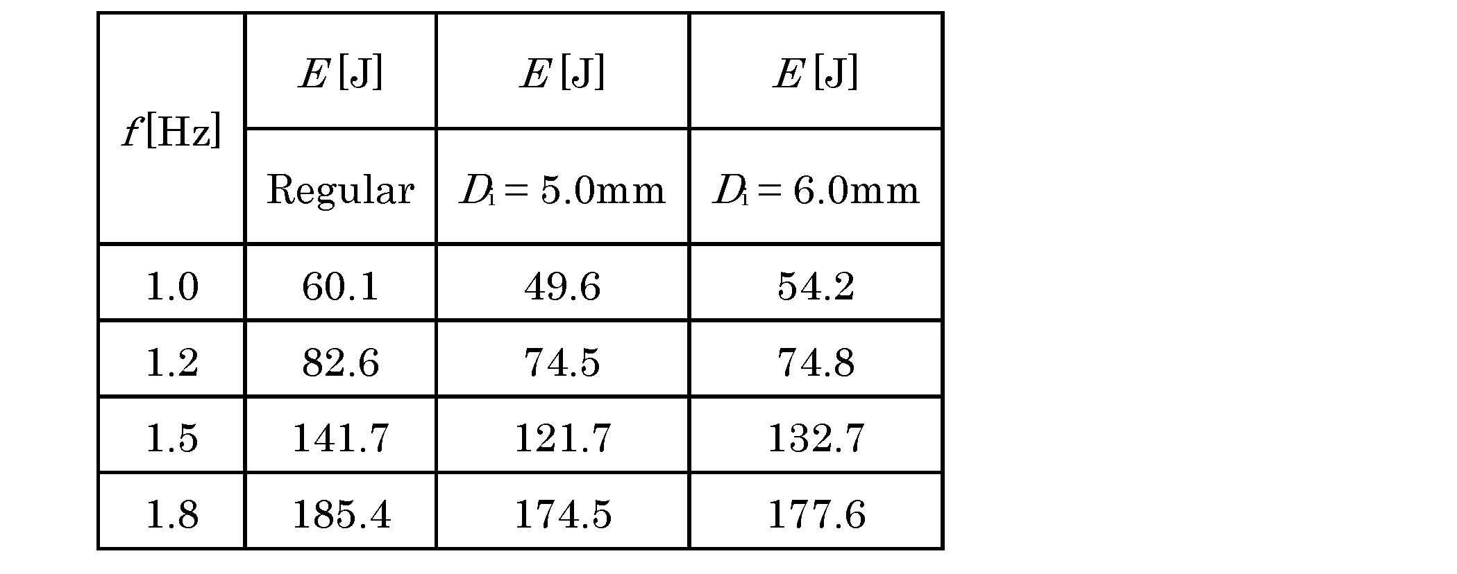
評価の結果から、いずれの管状部材を備えたものにおいても、収縮、膨張の振動数を変化させても、筒状部材の第2蓋部側の表面の過熱が、管状部材を使用していないものと比較して抑制され、更にエネルギー消費量も抑制されることが確認された。特に、管状部材の内径が小さいものの方が、筒状部材の第2蓋部側の表面の過熱が抑制され、エネルギー消費量も抑制されることが確認された。
10 第一実施形態の流体注入型人工筋アクチュエータ
10A 第二実施形態の流体注入型人工筋アクチュエータ
11 筒状部材
11a 筒状部材の一端部
11b 筒状部材の他端部
12 第1蓋部
121 第1蓋本体
122 第1固定部材
13 第2蓋部
131 第2蓋本体
132 第2固定部材
14 第1連通路
141 第1連通路の内部空間側の端部
142 第1連通路の外部空間側の端部
15 第2連通路
151 第2連通路の内部空間側の端部
152 第2連通路の外部空間側の端部
16 管状部材
R1 管状部材の外側領域
R2 管状部材の内側領域
LD 筒状部材の長手方向
L1 管状部材の長さ
L2 筒状部材の長さ
10A 第二実施形態の流体注入型人工筋アクチュエータ
11 筒状部材
11a 筒状部材の一端部
11b 筒状部材の他端部
12 第1蓋部
121 第1蓋本体
122 第1固定部材
13 第2蓋部
131 第2蓋本体
132 第2固定部材
14 第1連通路
141 第1連通路の内部空間側の端部
142 第1連通路の外部空間側の端部
15 第2連通路
151 第2連通路の内部空間側の端部
152 第2連通路の外部空間側の端部
16 管状部材
R1 管状部材の外側領域
R2 管状部材の内側領域
LD 筒状部材の長手方向
L1 管状部材の長さ
L2 筒状部材の長さ
Claims (7)
- 弾性を有する筒状部材と、
前記筒状部材の一端部をふさぐ第1蓋部と、
前記筒状部材の他端部をふさぐ第2蓋部と、
前記第1蓋部に形成され前記筒状部材の内部空間と外部空間とを連通させる第1連通路と、を備え、前記筒状部材の内部に流体を出し入れすることにより伸縮する流体注入型人工筋アクチュエータであって、
前記流体の出し入れに伴って生じる過熱を抑制する過熱抑制機構を更に備える流体注入型人工筋アクチュエータ。 - 前記過熱抑制機構は、前記筒状部材の内部空間における流体の滞留を抑制する機構である請求項1に記載の流体注入型人工筋アクチュエータ。
- 前記過熱抑制機構は、前記筒状部材の内部空間に、該筒状部材の長手方向に沿うように配置され、一端側が前記第1連通路に接続される管状部材を備える請求項1又は2に記載の流体注入型人工筋アクチュエータ。
- 前記筒状部材の内部空間側における前記管状部材の長さは、前記筒状部材の内部空間側における伸びた状態である前記筒状部材の長さの50%以上である請求項3に記載の流体注入型人工筋アクチュエータ。
- 前記管状部材は、可撓性を有する材料で構成される請求項3又は4に記載の流体注入型人工筋アクチュエータ。
- 前記第2蓋部に形成され前記筒状部材の内部空間と外部空間とを連通させる第2連通路を更に備え、
前記過熱抑制機構は、前記第1連通路及び前記第2連通路により構成される請求項1又は2に記載の流体注入型人工筋アクチュエータ。 - 請求項1から6いずれかに記載の流体注入型人工筋アクチュエータを備えるマニピュレータ。
Applications Claiming Priority (2)
| Application Number | Priority Date | Filing Date | Title |
|---|---|---|---|
| JP2013-250078 | 2013-12-03 | ||
| JP2013250078 | 2013-12-03 |
Publications (1)
| Publication Number | Publication Date |
|---|---|
| WO2015083567A1 true WO2015083567A1 (ja) | 2015-06-11 |
Family
ID=53273333
Family Applications (1)
| Application Number | Title | Priority Date | Filing Date |
|---|---|---|---|
| PCT/JP2014/080962 Ceased WO2015083567A1 (ja) | 2013-12-03 | 2014-11-21 | 流体注入型人工筋アクチュエータ及びマニピュレータ |
Country Status (1)
| Country | Link |
|---|---|
| WO (1) | WO2015083567A1 (ja) |
Cited By (2)
| Publication number | Priority date | Publication date | Assignee | Title |
|---|---|---|---|---|
| JP2017032022A (ja) * | 2015-07-30 | 2017-02-09 | 株式会社ブリヂストン | 流体圧アクチュエータ |
| CN110193824A (zh) * | 2019-04-19 | 2019-09-03 | 华中科技大学 | 一种软体致动器的运动控制方法 |
Citations (4)
| Publication number | Priority date | Publication date | Assignee | Title |
|---|---|---|---|---|
| JPS61130603A (ja) * | 1984-11-30 | 1986-06-18 | Bridgestone Corp | ニユ−マチツク・アクチユエ−タ |
| JPS62196408A (ja) * | 1986-02-24 | 1987-08-29 | Hitachi Ltd | アクチユエ−タ |
| JP2010156352A (ja) * | 2008-12-26 | 2010-07-15 | Olympus Corp | 細径アクチュエータ |
| JP2011148037A (ja) * | 2010-01-21 | 2011-08-04 | Tokai Rubber Ind Ltd | 形状記憶ポリマーを用いたアクチュエータおよびその制御方法 |
-
2014
- 2014-11-21 WO PCT/JP2014/080962 patent/WO2015083567A1/ja not_active Ceased
Patent Citations (4)
| Publication number | Priority date | Publication date | Assignee | Title |
|---|---|---|---|---|
| JPS61130603A (ja) * | 1984-11-30 | 1986-06-18 | Bridgestone Corp | ニユ−マチツク・アクチユエ−タ |
| JPS62196408A (ja) * | 1986-02-24 | 1987-08-29 | Hitachi Ltd | アクチユエ−タ |
| JP2010156352A (ja) * | 2008-12-26 | 2010-07-15 | Olympus Corp | 細径アクチュエータ |
| JP2011148037A (ja) * | 2010-01-21 | 2011-08-04 | Tokai Rubber Ind Ltd | 形状記憶ポリマーを用いたアクチュエータおよびその制御方法 |
Cited By (2)
| Publication number | Priority date | Publication date | Assignee | Title |
|---|---|---|---|---|
| JP2017032022A (ja) * | 2015-07-30 | 2017-02-09 | 株式会社ブリヂストン | 流体圧アクチュエータ |
| CN110193824A (zh) * | 2019-04-19 | 2019-09-03 | 华中科技大学 | 一种软体致动器的运动控制方法 |
Similar Documents
| Publication | Publication Date | Title |
|---|---|---|
| ATE538724T1 (de) | Antriebswelle für ein elektromechanisches chirurgisches gerät | |
| RU2009126752A (ru) | Самоподгоняющееся устройство для помещения в ушном канале | |
| JP2012529350A5 (ja) | ||
| WO2015083567A1 (ja) | 流体注入型人工筋アクチュエータ及びマニピュレータ | |
| JP2017514538A5 (ja) | ||
| JP2004210767A5 (ja) | ||
| ES2574558T3 (es) | Anilla para una tapa y proceso para fabricar dicha anilla | |
| BR112019008638A2 (pt) | dispositivo de proteção embólica, método de inclinação do mesmo e dispositivo de modelagem | |
| WO2016121060A1 (ja) | 硬度可変アクチュエータ | |
| KR20140078652A (ko) | 렌즈 주입기 장치 및 방법 | |
| ES2422183T3 (es) | Un dispositivo de ejercitación para músculo vaginal de una mujer | |
| CN101039715A (zh) | 可插入体内的装置及其制造方法 | |
| CA2862278A1 (en) | Fragmentation tip, intraocular surgery device provided with same, me thod for suppressing occurrence of cavitation, and use of the fragmentation tip in the treatment of cataracts | |
| JP2019528853A (ja) | 眼インプラント用のインジェクター | |
| US12317380B2 (en) | Cylindrical heater | |
| CN203230636U (zh) | 风扇减振结构 | |
| RU2447823C1 (ru) | Гибкий жидкостно-электрический нагреватель а. шевякова | |
| JP2016083364A (ja) | 眼内レンズ用インジェクタ | |
| JP6850056B1 (ja) | 術具 | |
| CL2018003521A1 (es) | Cuerpo de las aleaciones en formato laminar u otros, supresores de todo tipo de vaporizaciones y emisiones. | |
| CN210876675U (zh) | 一种牙科手机清洗固定座 | |
| JP2009030949A (ja) | 流体加熱要素を主に目的としたスパイラルインサート | |
| RU2665744C2 (ru) | Устройство для создания механических колебаний | |
| TH1901002390A (th) | สายสวนพ่นโพรงจมูกแบบยุบตัวได้ | |
| JP4373244B2 (ja) | 定着用加圧ローラ |
Legal Events
| Date | Code | Title | Description |
|---|---|---|---|
| 121 | Ep: the epo has been informed by wipo that ep was designated in this application |
Ref document number: 14867877 Country of ref document: EP Kind code of ref document: A1 |
|
| NENP | Non-entry into the national phase |
Ref country code: DE |
|
| 122 | Ep: pct application non-entry in european phase |
Ref document number: 14867877 Country of ref document: EP Kind code of ref document: A1 |
|
| NENP | Non-entry into the national phase |
Ref country code: JP |