WO2015083378A1 - 冷媒蒸発器 - Google Patents
冷媒蒸発器 Download PDFInfo
- Publication number
- WO2015083378A1 WO2015083378A1 PCT/JP2014/006055 JP2014006055W WO2015083378A1 WO 2015083378 A1 WO2015083378 A1 WO 2015083378A1 JP 2014006055 W JP2014006055 W JP 2014006055W WO 2015083378 A1 WO2015083378 A1 WO 2015083378A1
- Authority
- WO
- WIPO (PCT)
- Prior art keywords
- refrigerant
- core
- heat exchange
- core part
- leeward
- Prior art date
- Legal status (The legal status is an assumption and is not a legal conclusion. Google has not performed a legal analysis and makes no representation as to the accuracy of the status listed.)
- Ceased
Links
Images





Classifications
-
- F—MECHANICAL ENGINEERING; LIGHTING; HEATING; WEAPONS; BLASTING
- F25—REFRIGERATION OR COOLING; COMBINED HEATING AND REFRIGERATION SYSTEMS; HEAT PUMP SYSTEMS; MANUFACTURE OR STORAGE OF ICE; LIQUEFACTION SOLIDIFICATION OF GASES
- F25B—REFRIGERATION MACHINES, PLANTS OR SYSTEMS; COMBINED HEATING AND REFRIGERATION SYSTEMS; HEAT PUMP SYSTEMS
- F25B39/00—Evaporators; Condensers
- F25B39/02—Evaporators
-
- F—MECHANICAL ENGINEERING; LIGHTING; HEATING; WEAPONS; BLASTING
- F28—HEAT EXCHANGE IN GENERAL
- F28D—HEAT-EXCHANGE APPARATUS, NOT PROVIDED FOR IN ANOTHER SUBCLASS, IN WHICH THE HEAT-EXCHANGE MEDIA DO NOT COME INTO DIRECT CONTACT
- F28D1/00—Heat-exchange apparatus having stationary conduit assemblies for one heat-exchange medium only, the media being in contact with different sides of the conduit wall, in which the other heat-exchange medium is a large body of fluid, e.g. domestic or motor car radiators
- F28D1/02—Heat-exchange apparatus having stationary conduit assemblies for one heat-exchange medium only, the media being in contact with different sides of the conduit wall, in which the other heat-exchange medium is a large body of fluid, e.g. domestic or motor car radiators with heat-exchange conduits immersed in the body of fluid
- F28D1/04—Heat-exchange apparatus having stationary conduit assemblies for one heat-exchange medium only, the media being in contact with different sides of the conduit wall, in which the other heat-exchange medium is a large body of fluid, e.g. domestic or motor car radiators with heat-exchange conduits immersed in the body of fluid with tubular conduits
- F28D1/053—Heat-exchange apparatus having stationary conduit assemblies for one heat-exchange medium only, the media being in contact with different sides of the conduit wall, in which the other heat-exchange medium is a large body of fluid, e.g. domestic or motor car radiators with heat-exchange conduits immersed in the body of fluid with tubular conduits the conduits being straight
- F28D1/0535—Heat-exchange apparatus having stationary conduit assemblies for one heat-exchange medium only, the media being in contact with different sides of the conduit wall, in which the other heat-exchange medium is a large body of fluid, e.g. domestic or motor car radiators with heat-exchange conduits immersed in the body of fluid with tubular conduits the conduits being straight the conduits having a non-circular cross-section
- F28D1/05366—Assemblies of conduits connected to common headers, e.g. core type radiators
- F28D1/05391—Assemblies of conduits connected to common headers, e.g. core type radiators with multiple rows of conduits or with multi-channel conduits combined with a particular flow pattern, e.g. multi-row multi-stage radiators
-
- F—MECHANICAL ENGINEERING; LIGHTING; HEATING; WEAPONS; BLASTING
- F28—HEAT EXCHANGE IN GENERAL
- F28F—DETAILS OF HEAT-EXCHANGE AND HEAT-TRANSFER APPARATUS, OF GENERAL APPLICATION
- F28F1/00—Tubular elements; Assemblies of tubular elements
- F28F1/10—Tubular elements and assemblies thereof with means for increasing heat-transfer area, e.g. with fins, with projections, with recesses
- F28F1/12—Tubular elements and assemblies thereof with means for increasing heat-transfer area, e.g. with fins, with projections, with recesses the means being only outside the tubular element
- F28F1/126—Tubular elements and assemblies thereof with means for increasing heat-transfer area, e.g. with fins, with projections, with recesses the means being only outside the tubular element consisting of zig-zag shaped fins
-
- F—MECHANICAL ENGINEERING; LIGHTING; HEATING; WEAPONS; BLASTING
- F28—HEAT EXCHANGE IN GENERAL
- F28F—DETAILS OF HEAT-EXCHANGE AND HEAT-TRANSFER APPARATUS, OF GENERAL APPLICATION
- F28F9/00—Casings; Header boxes; Auxiliary supports for elements; Auxiliary members within casings
- F28F9/02—Header boxes; End plates
- F28F9/026—Header boxes; End plates with static flow control means, e.g. with means for uniformly distributing heat exchange media into conduits
- F28F9/028—Header boxes; End plates with static flow control means, e.g. with means for uniformly distributing heat exchange media into conduits by using inserts for modifying the pattern of flow inside the header box, e.g. by using flow restrictors or permeable bodies or blocks with channels
-
- F—MECHANICAL ENGINEERING; LIGHTING; HEATING; WEAPONS; BLASTING
- F28—HEAT EXCHANGE IN GENERAL
- F28F—DETAILS OF HEAT-EXCHANGE AND HEAT-TRANSFER APPARATUS, OF GENERAL APPLICATION
- F28F9/00—Casings; Header boxes; Auxiliary supports for elements; Auxiliary members within casings
- F28F9/22—Arrangements for directing heat-exchange media into successive compartments, e.g. arrangements of guide plates
-
- F—MECHANICAL ENGINEERING; LIGHTING; HEATING; WEAPONS; BLASTING
- F28—HEAT EXCHANGE IN GENERAL
- F28F—DETAILS OF HEAT-EXCHANGE AND HEAT-TRANSFER APPARATUS, OF GENERAL APPLICATION
- F28F9/00—Casings; Header boxes; Auxiliary supports for elements; Auxiliary members within casings
- F28F9/26—Arrangements for connecting different sections of heat-exchange elements, e.g. of radiators
- F28F9/262—Arrangements for connecting different sections of heat-exchange elements, e.g. of radiators for radiators
-
- F—MECHANICAL ENGINEERING; LIGHTING; HEATING; WEAPONS; BLASTING
- F25—REFRIGERATION OR COOLING; COMBINED HEATING AND REFRIGERATION SYSTEMS; HEAT PUMP SYSTEMS; MANUFACTURE OR STORAGE OF ICE; LIQUEFACTION SOLIDIFICATION OF GASES
- F25B—REFRIGERATION MACHINES, PLANTS OR SYSTEMS; COMBINED HEATING AND REFRIGERATION SYSTEMS; HEAT PUMP SYSTEMS
- F25B2339/00—Details of evaporators; Details of condensers
- F25B2339/02—Details of evaporators
Definitions
- the present disclosure relates to a refrigerant evaporator that cools a fluid to be cooled by absorbing heat from the fluid to be cooled and evaporating the refrigerant.
- the refrigerant evaporator functions as a cooling heat exchanger that cools the fluid to be cooled by absorbing heat from the fluid to be cooled (for example, air) flowing outside and evaporating the refrigerant (liquid phase refrigerant) flowing inside. .
- the first and second evaporation parts including a heat exchange core part formed by laminating a plurality of tubes and a pair of tank parts connected to both ends of the plurality of tubes are covered.
- a configuration is known in which the tanks are arranged in series in the flow direction of the cooling fluid, and one tank unit in each evaporation unit is connected via a pair of communication units (see, for example, Patent Document 1).
- the refrigerant that has flowed through the heat exchange core portion of the first evaporation portion is secondly passed through one tank portion of each evaporation portion and a pair of communication portions that connect the tank portions.
- the refrigerant flow is changed in the width direction (left-right direction) of the heat exchange core part. That is, in the refrigerant evaporator, the refrigerant flowing on one side in the width direction of the heat exchange core portion of the first evaporation portion is caused to flow in the width direction of the heat exchange core portion of the second evaporation portion by one of the pair of communication portions.
- the refrigerant is caused to flow to the other side, and the refrigerant flowing on the other side in the width direction of the heat exchange core part of the first evaporation part is caused to flow to one side in the width direction of the heat exchange core part of the second evaporation part. Yes.
- the liquid-phase refrigerant that has flowed into the first evaporation section tends to easily flow into a tube located near the liquid-phase refrigerant introduction section, and the laminated refrigerant is sufficiently flowed into a tube far from the introduction section. I can't. For this reason, while the liquid refrigerant sufficiently flows on one side in the width direction of the heat exchange core part of the second evaporation part, the refrigerant flowing on the other side in the width direction of the heat exchange core part of the second evaporation part passes through the superheated gas region. Become.
- This indication aims at providing the refrigerant evaporator which can control the deterioration of the distribution of a refrigerant in view of the above-mentioned point.
- the refrigerant evaporator includes a first evaporator and a second evaporator arranged in series with respect to the flow direction of the fluid to be cooled.
- Each of the first evaporation unit and the second evaporation unit has a heat exchange core unit configured by stacking a plurality of tubes through which a refrigerant flows.
- the heat exchange core part in the first evaporation part includes a first core part constituted by a part of the tube group and a second core part constituted by a tube group different from the first core part among the plurality of tubes. Have.
- the heat exchange core part in the second evaporation part includes a third core part composed of a tube group that faces at least a part of the first core part in the flow direction of the fluid to be cooled, and the fluid to be cooled.
- the fourth core portion is composed of a tube group facing at least a part of the second core portion in the flow direction.
- the refrigerant from the first core part is guided to the third core part, and the refrigerant from the second core part is guided to the fourth core part.
- At least one core part of the first core part and the second core part is a first small core part composed of a part of the tube group among the plurality of tubes belonging to the one core part, and the remaining tube group. It has the 2nd small core part comprised by these.
- the core portion facing one core portion is the first small portion in the flow direction of the fluid to be cooled among the plurality of tubes belonging to the core portion facing one core portion.
- a third small core part constituted by a tube group facing at least a part of the core part, and a fourth small part constituted by a tube group facing at least a part of the second small core part in the flow direction of the fluid to be cooled. It has a core part. The refrigerant from the first small core part is guided to the fourth small core part, and the refrigerant from the second small core part is guided to the third small core part.
- the first small core portion and the second small core portion are provided in at least one of the first core portion and the second core portion, and one of the third core portion and the fourth core portion is provided.
- Consists of a third small core part configured with a tube group facing at least a part of the first small core part, and a tube group facing at least a part of the second small core part on the core part facing the core part.
- the fourth small core portion is provided, and the refrigerant from the first small core portion is guided to the fourth small core portion, and the refrigerant from the second small core portion is guided to the third small core portion.
- the refrigerant flow can be exchanged in the width direction of the heat exchange core part (tube stacking direction).
- the refrigerant evaporator when the refrigerant evaporator is viewed from the flow direction of the fluid to be cooled, at least one of the first core portion and the second core portion in the heat exchange core portion of the first evaporation portion and the second evaporation portion.
- the liquid phase refrigerant can flow through the portion where the portion and the core portion opposite to the at least one core portion are polymerized. For this reason, it is possible to suppress the deterioration of refrigerant distribution.
- the refrigerant evaporator includes a first evaporator and a second evaporator disposed in series with respect to the flow direction of the fluid to be cooled.
- Each of the first evaporation unit and the second evaporation unit has a heat exchange core unit configured by stacking a plurality of tubes through which a refrigerant flows.
- the heat exchange core part in a 1st evaporation part has the 2nd core part comprised by the 1st core part comprised by some tube groups among some tubes, and the other some tube group.
- the heat exchange core part in the second evaporation part includes a third core part composed of a tube group that faces at least a part of the first core part in the flow direction of the fluid to be cooled, and the fluid to be cooled.
- the fourth core portion is composed of a tube group facing at least a part of the second core portion in the flow direction.
- the first evaporation unit and the second evaporation unit are configured such that the refrigerant from the first core unit is guided to the fourth core unit, and the refrigerant from the second core unit is guided to the third core unit.
- the first evaporation part is provided with a refrigerant introduction part for introducing the refrigerant into the first evaporation part.
- the heat exchange core part in a 1st evaporation part has the 5th core part comprised by tube groups other than the tube which belongs to a 1st core part and a 2nd core part among several tubes.
- the 1st core part, the 2nd core part, and the 5th core part are arranged in order of the 1st core part, the 2nd core part, and the 5th core part from the side near the refrigerant introduction part.
- the fifth core part faces at least a part of the fourth core part in the flow direction of the fluid to be cooled, and the refrigerant flowing out from the first core part is separated from the fourth core part and the fifth core part by the refrigerant distribution part. And distributed.
- the 5th core part which opposes at least one part of a 4th core part in the flow direction of a to-be-cooled fluid is provided in the heat exchange core part in a 1st evaporator, and the refrigerant
- the refrigerant distribution part that distributes the refrigerant to the fourth core part and the fifth core part
- the refrigerant flowing into the first core part is distributed to the fourth core part and the fifth core part by the refrigerant distribution part.
- the liquid-phase refrigerant can easily flow into the first core portion, The flow rate of the liquid-phase refrigerant distributed to the 4 core part and the 5th core part increases.
- the fifth core portion is opposed to at least a part of the fourth core portion in the flow direction of the fluid to be cooled, so that the refrigerant evaporator is far from the refrigerant introduction portion when viewed from the flow direction of the fluid to be cooled.
- the liquid phase refrigerant can be flowed to the overlapping portion of the fourth core portion and the fifth core portion, which is a portion where the liquid phase refrigerant is difficult to flow. For this reason, it is possible to suppress the deterioration of refrigerant distribution.
- the refrigerant evaporator includes a first evaporator and a second evaporator arranged in series with respect to the flow direction of the fluid to be cooled.
- Each of the first evaporation unit and the second evaporation unit has a heat exchange core unit configured by stacking a plurality of tubes through which a refrigerant flows.
- the heat exchange core part in a 1st evaporation part has the 2nd core part comprised by the 1st core part comprised by some tube groups among several tubes, and the remaining tube group.
- the heat exchange core part in the second evaporation part includes a third core part composed of a tube group that faces at least a part of the first core part in the flow direction of the fluid to be cooled, and the fluid to be cooled.
- the fourth core portion is composed of a tube group facing at least a part of the second core portion in the flow direction.
- the first evaporation unit and the second evaporation unit are configured such that the refrigerant from the first core unit is guided to the fourth core unit, and the refrigerant from the second core unit is guided to the third core unit.
- a refrigerant derivation unit for deriving the refrigerant from the inside of the second evaporation unit is provided on a side closer to the fourth core unit than the third core unit in the second evaporation unit.
- a refrigerant introduction flow path forming member that forms a refrigerant introduction flow path for introducing the refrigerant into the first evaporation section is connected to the first evaporation section.
- the refrigerant outlet part of the refrigerant introduction flow path forming member is connected to the side closer to the first core part than the second core part in the first evaporation part, and the refrigerant inlet part of the refrigerant introduction flow path forming member is the first It arrange
- the refrigerant from the first core part is guided to the fourth core part and the refrigerant from the second core part is guided to the third core part through the first evaporation part and the second evaporation part.
- the flow of the refrigerant can be exchanged in the width direction (tube stacking direction) of the heat exchange core part.
- the refrigerant is sucked toward the refrigerant outlet part.
- the part which a liquid phase refrigerant cannot flow easily to the side far from a refrigerant derivation part occurs.
- the first core portion and the third core portion in the heat exchange core portion of the first evaporation portion and the second evaporation portion overlap.
- a portion where the liquid-phase refrigerant does not flow easily is generated on the side far from the refrigerant outlet and the temperature distribution may be deteriorated.
- the refrigerant inlet part of the refrigerant introduction flow path forming member closer to the second core part than the first core part, in the refrigerant evaporator, the refrigerant inlet part of the refrigerant introduction flow path forming member and A refrigerant
- leading-out part can be arrange
- the refrigerant evaporator includes a first evaporator and a second evaporator disposed in series with respect to the flow direction of the fluid to be cooled.
- Each of the first evaporation unit and the second evaporation unit has a heat exchange core unit configured by stacking a plurality of tubes through which a refrigerant flows.
- a refrigerant introduction part for introducing the refrigerant into the first evaporation part is provided on one end part side in the stacking direction of the tubes in the first evaporation part.
- a refrigerant outlet section for extracting the refrigerant from the inside of the second evaporation section is provided on the same end side as the refrigerant introduction section in the tube stacking direction.
- the first evaporating unit and the second evaporating unit are connected via a communication unit that guides the refrigerant flowing out from the first evaporating unit to the end side opposite to the refrigerant deriving unit in the tube stacking direction in the second evaporating unit.
- a part where the liquid-phase refrigerant hardly flows is generated on the side far from the refrigerant introduction part in the heat exchange core part.
- a part where the liquid-phase refrigerant hardly flows is generated on the side far from the refrigerant outlet part in the heat exchange core part.
- the first evaporating unit and the second evaporating unit are connected to a communicating unit that guides the refrigerant that has flowed out of the first evaporating unit to the end side opposite to the refrigerant deriving unit in the tube stacking direction in the second evaporating unit.
- the liquid-phase refrigerant can easily flow to the side far from the refrigerant outlet in the heat exchange core of the second evaporator.
- the liquid phase refrigerant is applied to the entire region where the heat exchange core portion in the first evaporation portion and the heat exchange core portion in the second evaporation portion are polymerized. It can flow. For this reason, it is possible to suppress the deterioration of refrigerant distribution.
- the refrigerant evaporator 1 is applied to a vapor compression refrigeration cycle of a vehicle air conditioner that adjusts the temperature in the passenger compartment, and absorbs heat from the blown air that is blown into the passenger compartment to form a refrigerant (liquid phase refrigerant). It is a heat exchanger for cooling which cools blowing air by evaporating. In the present embodiment, the blown air corresponds to “cooled fluid flowing outside”.
- the refrigeration cycle includes a compressor, a radiator (condenser), an expansion valve, and the like (not shown) in addition to the refrigerant evaporator 1.
- the refrigeration cycle is received between the radiator and the expansion valve. It is comprised as a receiver cycle which arrange
- the refrigerant of the refrigeration cycle is mixed with refrigeration oil for lubricating the compressor, and a part of the refrigeration oil circulates in the cycle together with the refrigerant.
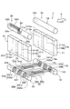
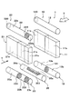
- the refrigerant evaporator 1 includes two evaporators 10 and 20 arranged in series with respect to the flow direction (flow direction of the fluid to be cooled) X of the blown air. It is prepared for.
- positioned among the two evaporation parts 10 and 20 on the windward side (upstream side) of the air flow direction of blowing air is called the windward evaporation part 10, and the flow of blowing air
- the evaporator disposed on the leeward side (downstream side) in the direction is referred to as a leeward evaporator 20.
- the windward evaporator 10 in this embodiment constitutes a “second evaporator”
- the leeward evaporator 20 constitutes a “first evaporator”.
- the basic configurations of the windward side evaporator 10 and the leeward side evaporator 20 are the same, and the heat exchange core parts 11 and 21 and a pair of tank parts 12 disposed on the upper and lower sides of the heat exchange core parts 11 and 21, respectively. 13, 22, and 23.
- the heat exchange core part in the windward side evaporation part 10 is called the windward heat exchange core part 11
- the heat exchange core part in the leeward side evaporation part 20 is called the leeward side heat exchange core part 21.
- the tank portion disposed on the upper side is referred to as a first windward tank portion 12
- the tank portion disposed on the lower side is referred to as the second windward side. This is referred to as a tank portion 13.
- the tank part arranged on the upper side is referred to as the first leeward side tank part 22, and the tank part arranged on the lower side is referred to as the second leeward side. This is referred to as a side tank portion 23.
- Each of the windward side heat exchange core part 11 and the leeward side heat exchange core part 21 of the present embodiment includes a plurality of tubes 111 and 211 extending in the vertical direction and fins 112 and 212 joined between the adjacent tubes 111 and 211. And a laminate in which layers are alternately arranged.
- the stacking direction in the stacked body of the plurality of tubes 111 and 211 and the plurality of fins 112 and 212 is referred to as a tube stacking direction.
- the windward side heat exchange core part 11 is the 2nd wind comprised by the 1st windward heat exchange core part 11a comprised by some tube groups among the some tubes 111, and the remaining tube group. It has the upper side heat exchange core part 11b.
- the 1st windward heat exchange core part 11a in this embodiment comprises a "3rd core part”
- the 2nd windward heat exchange core part 11b comprises a "4th core part.”
- the first windward heat exchange core part 11a is configured by a tube group existing on the right side of the tube lamination direction, and the tube lamination direction
- the second upwind heat exchange core portion 11b is configured by a tube group existing on the left side of the above.
- the leeward side heat exchange core part 21 is the 2nd leeward side comprised by the 1st leeward side heat exchange core part 21a comprised by some tube groups among the some tubes 211, and the remaining tube group. It has a heat exchange core portion 21b.
- the 1st leeward side heat exchange core part 21a in this embodiment comprises a "1st core part”
- the 2nd leeward side heat exchange core part 21b comprises a "2nd core part.”
- the first leeward heat exchange core portion 21a when the leeward heat exchange core portion 21 is viewed from the flow direction of the blown air, the first leeward heat exchange core portion 21a is configured by a tube group existing on the right side of the tube lamination direction, and the tube lamination direction
- the second leeward heat exchange core portion 21b is configured by a tube group existing on the left side of the leeward side.
- the first windward side heat exchange core portion 11a and the first leeward side heat exchange core portion 21a are arranged so as to overlap (opposite) when viewed from the flow direction of the blown air.
- the second leeward side heat exchange core part 11b and the second leeward side heat exchange core part 21b are arranged so as to overlap (oppose) each other.
- Each of the tubes 111 and 211 is formed of a flat tube in which a refrigerant passage through which a refrigerant flows is formed and a cross-sectional shape thereof is a flat shape extending along the flow direction of the blown air.
- the tube 111 of the windward side heat exchange core part 11 has one end side (upper end side) in the longitudinal direction connected to the first windward tank part 12, and the other end side (lower end side) in the longitudinal direction is the second windward side. It is connected to the tank unit 13.
- the tube 211 of the leeward heat exchange core portion 21 has one end side (upper end side) in the longitudinal direction connected to the first leeward tank portion 22 and the other end side (lower end side) in the longitudinal direction is second.
- the leeward tank unit 23 is connected.
- Each of the fins 112 and 212 is a corrugated fin formed by bending a thin plate material into a wave, joined to the flat outer surface side of the tubes 111 and 211, and heat for expanding the heat transfer area between the blown air and the refrigerant.
- the exchange promotion part is configured.
- side plates 113 and 213 that reinforce the heat exchange core parts 11 and 21 are arranged at both ends in the tube lamination direction.
- the side plates 113 and 213 are joined to the fins 112 and 212 arranged on the outermost side in the tube stacking direction.
- the first upwind tank unit 12 is closed at one end (the left end when viewed from the flow direction of the blown air) and at the other end (the right end when viewed from the flow direction of the blown air). Further, it is composed of a cylindrical member in which a refrigerant outlet 120 for leading the refrigerant from the inside of the tank to the suction side of a compressor (not shown) is formed.
- the first upwind tank unit 12 has a through hole (not shown) in which one end side (upper end side) of each tube 111 is inserted and joined at the bottom.
- the first upwind tank unit 12 is configured such that the internal space thereof communicates with each tube 111 of the upwind heat exchange core unit 11, and the core units 11 a and 11 b of the upwind heat exchange core unit 11. It functions as a refrigerant collecting part that collects the refrigerant from.
- the first leeward tank section 22 is closed at one end, and has a cylinder formed with a refrigerant introduction section 220 for introducing low-pressure refrigerant decompressed by an expansion valve (not shown) into the tank at the other end. It is comprised by the shape-shaped member.
- the first leeward tank portion 22 has a through hole (not shown) in which one end side (upper end side) of each tube 211 is inserted and joined at the bottom. That is, the 1st leeward side tank part 22 is comprised so that the internal space may connect with each tube 211 of the leeward side heat exchange core part 21, and each core part 21a, 21b of the leeward side heat exchange core part 21 is comprised. It functions as a refrigerant distribution unit that distributes the refrigerant.
- the second upwind tank unit 13 is composed of a cylindrical member whose both ends are closed.
- the second upwind tank portion 13 has a through hole (not shown) in which the other end side (lower end side) of each tube 111 is inserted and joined to the ceiling portion. That is, the second upwind tank unit 13 is configured such that its internal space communicates with each tube 111.
- a first partition member 131 is disposed at a central position in the longitudinal direction inside the second windward tank section 13, and the tank interior space is formed by the first partition member 131 so that the first windward heat exchange core is disposed. It is partitioned into a space where each tube 111 composing the portion 11a communicates and a space where each tube 111 composing the second upwind heat exchange core portion 11b communicates.
- the space communicating with each tube 111 constituting the first upwind heat exchange core unit 11a distributes the refrigerant to the first upwind heat exchange core unit 11a.
- a second refrigerant distributor that constitutes the first refrigerant distributor 13a and that communicates with the tubes 111 constituting the second windward heat exchange core 11b distributes the refrigerant to the second windward heat exchange core 11b. 13b is constituted.
- the second leeward tank portion 23 is formed of a cylindrical member whose both ends are closed.
- the second leeward tank portion 23 has a through hole (not shown) in which the other end side (lower end side) of each tube 211 is inserted and joined to the ceiling portion. That is, the second leeward tank unit 23 is configured such that the internal space thereof communicates with each tube 211.
- a second partition member 231 is disposed inside the second leeward tank unit 23 at a central position in the longitudinal direction, and the second partition member 231 causes the tank internal space to be in the first leeward heat exchange core unit 21a.
- the second partition member 231 causes the tank internal space to be in the first leeward heat exchange core unit 21a.
- the space communicating with each tube 211 constituting the first leeward side heat exchange core part 21a collects the refrigerant from the first leeward side heat exchange core part 21a.
- the second refrigerant that constitutes the first refrigerant collecting portion 23a to be communicated and in which the space where the tubes 211 constituting the second leeward heat exchange core portion 21b communicate with each other collects refrigerant from the second leeward heat exchange core portion 21b.
- the aggregation unit 23b is configured.
- the 1st windward heat exchange core part 11a is the 1st windward comprised by some tube groups among the some tubes 111 which comprise the 1st windward heat exchange core part 11a. It has the 2nd windward small core part 112a comprised by the small core part 111a and the remaining tube group.
- the 1st windward small core part 111a in this embodiment comprises a "3rd small core part”
- the 2nd windward small core part 112a comprises a "4th small core part.”
- the 1st windward small core part 111a when the 1st windward heat exchange core part 11a is seen from the flow direction of blowing air, the 1st windward small core part 111a is comprised by the tube group which exists in the right side of a tube lamination direction, and tube lamination
- the second windward small core portion 112a is configured by a tube group existing on the left side in the direction.
- the second upwind heat exchange core portion 11b includes a third upwind small core portion 111b constituted by a part of a tube group among the plurality of tubes 111 constituting the second upwind heat exchange core portion 11b, and the remaining portion.
- the 4th windward small core part 112b comprised by these tube groups is provided.
- the 3rd windward small core part 111b in this embodiment comprises a "3rd small core part”
- the 4th windward small core part 112b comprises a "4th small core part.”
- the third upwind small core portion 111b is configured by a tube group existing on the right side of the tube stacking direction, and the tube stacking is performed.
- the fourth windward small core portion 112b is configured by a group of tubes existing on the left side in the direction.
- the 1st leeward side heat exchange core part 21a is the 1st leeward side small core part 211a comprised by some tube groups among the some tubes 211 which comprise the 1st leeward side heat exchange core part 21a, and the remainder.
- the 2nd leeward side small core part 212a comprised by these tube groups is provided.
- the 1st leeward side small core part 211a in this embodiment comprises a "1st small core part”
- the 2nd leeward side small core part 212a comprises a "2nd small core part.”
- the 1st leeward side small core part 211a when the 1st leeward side heat exchange core part 21a is seen from the flow direction of blowing air, the 1st leeward side small core part 211a is comprised with the tube group which exists in the right side of a tube lamination direction, and tube lamination
- the second leeward small core portion 212a is configured by a tube group existing on the left side in the direction.
- the first downwind small core portion 111a and the first downwind small core portion 211a are arranged so as to overlap (opposite) when viewed from the flow direction of the blown air.
- the two leeward small core portions 112a and the second leeward small core portion 212a are arranged so as to overlap (oppose) each other.
- the second leeward side heat exchange core part 21b includes a third leeward side small core part 211b constituted by a part of the tube group among the plurality of tubes 211 constituting the second leeward side heat exchange core part 21b, and the remaining part. 4th leeward side small core part 212b comprised by these tube groups.
- the 3rd leeward side small core part 211b in this embodiment comprises a "1st small core part”
- the 4th leeward side small core part 212b comprises a "2nd small core part.”
- the third leeward side small core portion 211b is configured by a tube group existing on the right side in the tube stacking direction
- a tube group existing on the left side of the direction constitutes the fourth leeward small core portion 212b.
- the third windward small core portion 111b and the third leeward small core portion 211b are arranged so as to overlap (oppose) when viewed from the flow direction of the blown air, and the first The 4 leeward small cores 112b and the 4th leeward small core 212b are arranged so as to overlap (oppose) each other.
- a third partition member 221 is disposed inside the first leeward tank unit 22, and the third partition member 221 allows the tank internal space to be formed into a first leeward heat exchange core unit 21 a (first leeward side small size).
- the section 211b) is partitioned into spaces in which the tubes 211 constituting the section 212b) communicate with each other.
- the space communicating with each tube 211 constituting the first leeward side heat exchange core part 21a distributes the refrigerant to the first leeward side heat exchange core part 21a.
- the second refrigerant distribution unit that configures the first refrigerant distribution unit 22a and that communicates with the tubes 211 that configure the second leeward heat exchange core unit 21b distributes the refrigerant to the second leeward heat exchange core unit 21b. 22b is configured.
- a fourth partition member 232 is disposed inside the first refrigerant collecting portion 23a of the second leeward tank portion 23 at the center position in the longitudinal direction of the first refrigerant collecting portion 23a.
- the fourth partition member 232 the space in which the tubes 211 constituting the first leeward small core portion 211a communicate with the first refrigerant collecting portion 23a and the tubes 211 constituting the second leeward small core portion 212a are formed. It is partitioned into a communicating space.
- a fifth partition member 233 is disposed inside the second refrigerant collecting portion 23b of the second leeward tank portion 23 at the center position in the longitudinal direction of the second refrigerant collecting portion 23b.
- the fifth partitioning member 233 the space in which the tubes 211 constituting the third leeward small core portion 211b communicate with the second refrigerant collecting portion 23b and the tubes 211 constituting the fourth leeward small core portion 212b are formed. It is partitioned into a communicating space.
- a sixth partition member 132 is disposed inside the first refrigerant distributor 13a of the second upwind tank unit 13 at the center position in the longitudinal direction of the first refrigerant distributor 13a.
- the space in which the tubes 111 constituting the first windward small core portion 111a communicate with the first refrigerant distribution portion 13a and the tubes 111 constituting the second windward small core portion 112a are connected. It is partitioned into a communicating space.
- the space communicating with each tube 111 constituting the first windward small core part 111a distributes the refrigerant to the first windward small core part 111a.
- a space that communicates with each tube 111 that constitutes 131a and constitutes the second upwind small core portion 112a constitutes a second small distribution portion 132a that distributes the refrigerant to the second upwind small core portion 112a.
- the 7th partition member 133 is arranged in the 2nd refrigerant distribution part 13b of the 2nd windward side tank part 13 in the central position of the longitudinal direction of the 2nd refrigerant distribution part 13b.
- the seventh partition member 133 allows the second refrigerant distribution portion 13b to communicate with the space where the tubes 111 constituting the third windward small core portion 111b communicate with each tube 111 constituting the fourth windward small core portion 112b. It is partitioned into a communicating space.
- a space communicating with each tube 111 constituting the third upwind small core unit 111b distributes the refrigerant to the third upwind small core unit 111b.
- a space communicating with each tube 111 constituting the fourth upwind small core portion 112b constitutes a fourth small distribution portion 132b that distributes the refrigerant to the fourth upwind small core portion 112b.
- the second leeward tank unit 13 and the second leeward tank unit 23 are connected via a first refrigerant replacement unit 31 and a second refrigerant replacement unit 32, respectively.
- the first refrigerant replacement unit 31 guides the refrigerant in the first small collection unit 231a in the second leeward tank unit 23 to the second small distribution unit 132a in the second leeward tank unit 13, and the second leeward tank unit
- the refrigerant in the second small collecting portion 232a at 23 is guided to the first small distribution portion 131a in the second upwind tank portion 13.
- exchange part 31 is comprised so that the flow of a refrigerant
- the second refrigerant replacement unit 32 guides the refrigerant in the third small collection unit 231b in the second leeward tank unit 23 to the fourth small distribution unit 132b in the second leeward tank unit 13 and also the second leeward tank unit.
- the refrigerant in the fourth small collecting portion 232b at 23 is guided to the third small distributing portion 131b in the second upwind tank portion 13. That is, the 2nd refrigerant
- the first refrigerant replacement part 31 communicates the first small collecting part 231a in the second leeward tank part 23 and the second small distribution part 132a in the second leeward tank part 13 with each other.
- a second connecting member 31b that allows the second small collecting portion 232a in the second leeward tank portion 23 and the first small distribution portion 131a in the second leeward tank portion 13 to communicate with each other.
- Each of the first connecting member 31a and the second connecting member 31b is composed of a cylindrical member in which a refrigerant flow passage through which a refrigerant flows is formed.
- the first connecting member 31 a and the second connecting member 31 b are joined to each other in a state of being disposed adjacent to the longitudinal direction of the tubes 111 and 211.
- the second refrigerant replacement unit 32 includes a third connecting member 32a that communicates the third small collecting portion 231b in the second leeward tank portion 23 and the fourth small distributing portion 132b in the second leeward tank portion 13, and a second leeward
- the fourth small collecting portion 232b in the side tank portion 23 and the fourth connecting member 32b for communicating the third small distribution portion 131b in the second upwind tank portion 13 are configured.
- Each of the 3rd connection member 32a and the 4th connection member 32b is comprised by the cylindrical member in which the refrigerant
- the 3rd connection member 32a and the 4th connection member 32b are mutually joined in the state arrange
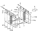
- the low-pressure refrigerant decompressed by an expansion valve (not shown) is introduced into the tank from the refrigerant introduction part 220 of the first leeward tank part 22 as indicated by an arrow A.
- a part of the refrigerant introduced into the first leeward tank unit 22 flows into the first refrigerant distribution unit 22a as shown by an arrow B, and the remaining refrigerant introduced into the first leeward tank unit 22 is As shown by the arrow C, the refrigerant flows into the second refrigerant distributor 22b.
- the refrigerant that has flowed into the first refrigerant distribution portion 22a descends the first leeward side small core portion 211a of the leeward side heat exchange core portion 21 as indicated by an arrow D, and the first small aggregate portion 231a of the second leeward side tank portion 23.
- the second leeward small core portion 212a of the leeward heat exchange core portion 21 descends and flows into the second small collecting portion 232a of the second leeward tank portion 23.
- the refrigerant that has flowed into the second refrigerant distribution part 22b descends the third leeward small core part 211b of the leeward heat exchange core part 21 as indicated by the arrow F, and the third small collecting part 231b of the second leeward tank part 23.
- the fourth leeward small core portion 212b of the leeward heat exchange core portion 21 descends and flows into the fourth small gathering portion 232b of the second leeward tank portion 23.
- the refrigerant that has flowed into the first small collecting portion 231a flows into the second small distribution portion 132a of the second upwind tank portion 13 through the first connecting member 31a as indicated by an arrow H.
- the refrigerant that has flowed into the first small collecting portion 231a flows into the first small distribution portion 131a of the second upwind tank portion 13 through the second connecting member 31b as indicated by an arrow I.
- the refrigerant that has flowed into the third small collecting portion 231b flows into the fourth small distributing portion 132b of the second upwind tank portion 13 through the third connecting member 32a as indicated by an arrow J.
- the refrigerant that has flowed into the fourth small collecting portion 232b flows into the third small distributing portion 131b of the second upwind tank portion 13 through the fourth connecting member 32b as indicated by an arrow K.
- the refrigerant that has flowed into the second small distribution portion 132a moves up the second windward small core portion 112a of the windward heat exchange core portion 11 as indicated by an arrow L and flows into the tank of the first windward tank portion 12.
- the refrigerant that has flowed into the first small distribution part 131a ascends the first windward small core part 111a of the windward heat exchange core part 11 as indicated by an arrow M and flows into the tank of the first windward tank part 12.
- the refrigerant that has flowed into the fourth small distribution portion 132b moves up the fourth windward small core portion 112b of the windward heat exchange core portion 11 as indicated by an arrow N and flows into the tank of the first windward tank portion 12.
- the refrigerant that has flowed into the third small distribution part 131b moves up the third windward small core part 111b of the windward heat exchange core part 11 as indicated by an arrow O and flows into the tank of the first windward tank part 12.
- the refrigerant that has flowed into the tank of the first upwind tank section 12 is led out from the refrigerant outlet section 120 of the first upwind tank section 12 to the compressor (not shown) suction side as indicated by an arrow P.
- the flow of the refrigerant flowing into the first upwind heat exchange core portion 11a (hereinafter referred to as the first refrigerant flow) is replaced in the core width direction by the first refrigerant replacement portion 31.
- the flow of the refrigerant flowing into the second upwind heat exchange core portion 11b (hereinafter referred to as the second refrigerant flow) is replaced in the core width direction by the second refrigerant replacement portion 32.
- the refrigerant flowing on one side in the width direction of the conventional refrigerant evaporator 1, that is, the leeward side heat exchange core part 21 is changed to the width of the upside heat exchange core part 11.
- the refrigerant evaporator 1 configured to flow to the other side in the direction and to flow the refrigerant flowing on the other side in the width direction of the leeward heat exchange core portion 21 to one side in the width direction of the upwind heat exchange core portion 11,
- the evaporator 1 is viewed from the air flow direction, there is a possibility that the liquid-phase refrigerant cannot flow over the entire polymerization site in the windward side heat exchange core part 11 and the leeward side heat exchange core part 21.
- the first refrigerant flow is replaced in the core width direction by the first refrigerant replacement unit 31, and the second refrigerant flow is replaced in the core width direction by the second refrigerant replacement unit 32.
- the liquid-phase refrigerant can be caused to flow over the entire region to be polymerized in the windward side heat exchange core part 11 and the leeward side heat exchange core part 21.
- the third partition member 221 is arranged inside the first leeward tank unit 22 and the flow of the refrigerant flowing from the refrigerant introduction unit 220 is distributed to the first refrigerant flow and the second refrigerant flow.
- refrigerant replacement units 31 and 32 are provided for the first refrigerant flow and the second refrigerant flow, respectively.
- the performance of the refrigerant evaporator 1 can be improved. For this reason, even if the refrigerant
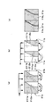
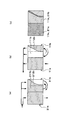
- FIG. 4 is an explanatory diagram for explaining the distribution of the liquid-phase refrigerant flowing through the heat exchange core portions 11 and 21 of the refrigerant evaporator 1 according to the first embodiment.
- FIG. 4A shows the distribution of the liquid phase refrigerant flowing through the leeward heat exchange core portion 21, and FIG. 4B shows the distribution of the liquid phase refrigerant flowing through the windward heat exchange core portion 11, and FIG. (C) has shown the synthesis
- FIG. 4 shows the distribution of the liquid-phase refrigerant when the refrigerant evaporator 1 is viewed from the direction of the arrow Y in FIG. 1 (the direction opposite to the flow direction X of the blown air), and is shown by the shaded portion in the figure.
- a part shows the part in which a liquid phase refrigerant exists.
- the liquid-phase refrigerant flowing through the windward side heat exchange core part 11 as shown in FIG. 4B, the first windward side heat exchange core part 11a and the second windward side heat exchange core part 11b, respectively.
- the liquid-phase refrigerant is difficult to flow in the portion excluding a part of the small core portion (the second windward small core portion 112 a and the fourth windward small core portion 112 b) far from the refrigerant lead-out portion 120 (in the drawing). White spots).
- the first upwind heat exchange core portion 11a, the first downwind heat exchange core portion 21a, the first refrigerant distribution portion 13a, and the first refrigerant assembly portion 23a are: It is not divided in the core width direction.
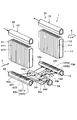
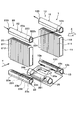
- the second leeward tank unit 13 and the second leeward tank unit 23 are connected via an intermediate tank unit 34 that is a refrigerant replacement unit.
- the refrigerant replacement section guides the refrigerant in the first refrigerant collecting section 23a in the second leeward tank section 23 to the first refrigerant distribution section 13a in the second leeward tank section 13, and further in the second leeward tank section 23.
- the refrigerant in the third small collecting portion 231b is guided to the fourth small distributing portion 132b in the second leeward tank portion 13, and the refrigerant in the fourth small collecting portion 232b in the second leeward tank portion 23 is transferred to the second windward tank.
- the unit 13 is configured to guide the third small distribution unit 131b.
- the refrigerant replacement unit is configured to exchange the second refrigerant flow in the core width direction in the second upwind heat exchange core unit 11b and the second downwind heat exchange core unit 21b.
- the refrigerant replacement unit of the present embodiment includes an intermediate tank unit 34.
- the intermediate tank part 34 is comprised by the cylindrical member by which the both end sides were obstruct
- the intermediate tank portion 34 is disposed between the second leeward tank portion 13 and the second leeward tank portion 23.
- a first partition member 341 that divides the space inside the tank into two small spaces in the core width direction is arranged at the center in the core width direction inside the intermediate tank portion 34.
- a second partition member 342 is disposed in a portion located on the upper side in a small space far from the refrigerant introduction portion 220 among the two small spaces of the intermediate tank portion 34.
- the first refrigerant flow passage 34a constitutes a refrigerant flow passage that guides the refrigerant from the first refrigerant collecting portion 23a to the first refrigerant distribution portion 13a.
- the second refrigerant flow passage 34b constitutes a refrigerant flow passage that guides the refrigerant from the third small collecting portion 231b to the fourth small distribution portion 132b.
- the third refrigerant flow passage 34c constitutes a refrigerant flow path that guides the refrigerant from the fourth small collecting portion 232b to the third small distribution portion 131b.
- FIG. 7 is an explanatory diagram for explaining the distribution of the liquid-phase refrigerant flowing through the heat exchange core portions 11 and 21 of the refrigerant evaporator 1 according to the second embodiment.
- FIG. 7A shows the distribution of the liquid phase refrigerant flowing through the leeward heat exchange core portion 21, and FIG. 7B shows the distribution of the liquid phase refrigerant flowing through the windward heat exchange core portion 11.
- C has shown the synthesis
- FIG. FIG. 7 shows the distribution of the liquid-phase refrigerant when the refrigerant evaporator 1 is viewed from the direction of arrow Y in FIG. 5 (the direction opposite to the flow direction X of the blown air), and is shown by the shaded portion in the figure.
- a part shows the part in which a liquid phase refrigerant exists.
- the small core on the side far from the refrigerant introduction portion 220 is used.
- a part (a white spot in the figure) where the liquid refrigerant hardly flows is generated in a part of the fourth leeward side small core part 212b.
- the second leeward side heat exchange core part 21b far from the refrigerant introduction part 220.
- the refrigerant flow in the core width direction It is configured to be replaced with.
- the refrigerant evaporator 1 configured to replace the refrigerant flow in the core width direction on the entire surface of the windward side heat exchange core portion 11 and the leeward side heat exchange core portion 21.
- the area of the portion where the refrigerant flow is exchanged in the core width direction is reduced.
- polymerization is performed on the heat exchange core parts 11 and 21 on the side far from the refrigerant introduction part 220 and the refrigerant outlet part 120 having poor liquid phase distribution.
- the liquid phase refrigerant can surely flow through the entire area. For this reason, it is possible to reliably suppress deterioration in refrigerant distribution.
- a third embodiment will be described with reference to the drawings.
- the third embodiment replaces the first refrigerant flow and the second refrigerant flow in the core width direction, and also part of the first refrigerant flow that has flowed into the second upwind tank unit 13. Is different in that it is branched so as to flow again into the leeward heat exchange core portion 21.
- the leeward heat exchange core portion 21 includes a first leeward heat exchange core portion 21a, a second leeward heat exchange core portion 21b, and a third leeward heat exchange core portion 21c. is doing.
- the 3rd leeward side heat exchange core part 21c is arrange
- the 3rd leeward side heat exchange core part 21c in this embodiment comprises a "5th core part.”
- the third leeward heat exchange core portion 21c is arranged so as to overlap (oppose) with a part of the second leeward heat exchange core portion 11b when viewed from the flow direction of the blown air. Yes.
- a partition member 223 is disposed inside the first leeward tank portion 22 on the side far from the refrigerant introduction portion 220 in the longitudinal direction.
- the tank internal space of the first leeward side tank portion 22 communicates with the space where the tubes 211 constituting the first leeward side heat exchange core portion 21a and the second leeward side heat exchange core portion 21b communicate with each other.
- the three leeward side heat exchange core portions 21c are partitioned into spaces through which the respective tubes 211 are communicated.
- the space communicating with the respective tubes 211 constituting the first leeward side heat exchange core portion 21a and the second leeward side heat exchange core portion 21b is the first leeward side.
- coolant from the 3 leeward side heat exchange core part 21c is comprised.
- a partition member 232 is disposed inside the second refrigerant collecting portion 23b of the second leeward tank portion 23.
- the partition member 232 and the second partition member 231 allow the tank internal space of the second leeward tank portion 23 to communicate with the space where the tubes 211 constituting the first leeward heat exchange core portion 21a communicate with each other, and the second leeward heat. It is partitioned into a space in which each tube 211 constituting the exchange core portion 21b communicates and a space in which each tube 211 constituting the third leeward side heat exchange core portion 21c communicates.
- the space communicating with each tube 211 constituting the first leeward side heat exchange core part 21a collects the refrigerant from the first leeward side heat exchange core part 21a.
- the second refrigerant that constitutes the first refrigerant collecting portion 23a to be communicated and in which the space where the tubes 211 constituting the second leeward heat exchange core portion 21b communicate with each other collects refrigerant from the second leeward heat exchange core portion 21b.
- a space that constitutes the collecting portion 23b and communicates with the tubes 211 that constitute the third leeward heat exchange core portion 21c constitutes a refrigerant distribution portion 23c that distributes the refrigerant to the third leeward heat exchange core portion 21c.
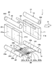
- the second leeward tank unit 13 and the second leeward tank unit 23 are connected via an intermediate tank unit 35 that is a refrigerant replacement unit.
- the refrigerant replacement part guides the refrigerant in the first refrigerant assembly part 23a in the second leeward tank part 23 to the second refrigerant distribution part 13b in the second leeward tank part 13 and also in the second leeward tank part 23.
- the refrigerant in the second refrigerant collecting portion 23 b is configured to be guided to the first refrigerant distributing portion 13 a in the second upwind tank portion 13. That is, the refrigerant replacement unit is configured to replace the refrigerant flow in the core width direction in the second upwind heat exchange core unit 11b and the second downwind heat exchange core unit 21b.
- the refrigerant replacement unit of the present embodiment includes an intermediate tank unit 35.
- the intermediate tank part 35 is comprised by the cylindrical member by which the both end sides were obstruct
- the intermediate tank portion 35 is disposed between the second leeward tank portion 13 and the second leeward tank portion 23.
- a partition member 351 is disposed at a position located on the upper side.
- the partition member 351 partitions the space inside the tank into a first refrigerant flow passage 35a and a second refrigerant flow passage 35b.
- the first refrigerant flow passage 34 a constitutes a refrigerant flow passage that guides the refrigerant in the first refrigerant assembly portion 23 a in the second leeward tank portion 23 to the second refrigerant distribution portion 13 b in the second leeward tank portion 13.
- the second refrigerant flow passage 34b constitutes a refrigerant flow passage that guides the refrigerant in the second refrigerant assembly portion 23b in the second leeward tank portion 23 to the first refrigerant distribution portion 13a in the second leeward tank portion 13. ing.
- a first through hole 134 is formed at an end portion on the side far from the refrigerant outlet section 120 in the longitudinal direction.
- the first through hole 134 is provided on a surface facing the second leeward tank portion 23.
- a second through hole 234 is formed at an end portion far from the refrigerant introduction portion 220 in the longitudinal direction.
- the second through hole 234 is a surface facing the second upwind tank unit 13 and is provided at a site corresponding to the first through hole 134.
- the peripheral portion of the second through hole 234 is joined to the peripheral portion of the first through hole 134. For this reason, the refrigerant in the second refrigerant distribution portion 13b in the second upwind tank portion 13 passes through the first through hole 134 and the second through hole 234 to the refrigerant distribution portion 23c in the second leeward tank portion 23. Led.
- a third through hole 124 is formed at an end portion on the side far from the refrigerant outlet section 120 in the longitudinal direction.
- the third through hole 124 is provided on the surface facing the first leeward tank unit 22.
- a fourth through hole 224 is formed at an end portion far from the refrigerant introduction portion 220 in the longitudinal direction.
- the fourth through hole 224 is a surface facing the first upwind tank section 12 and is provided at a site corresponding to the third through hole 124.
- the peripheral portion of the fourth through hole 224 is joined to the peripheral portion of the third through hole 124. For this reason, the refrigerant in the refrigerant assembly 322b in the first leeward tank unit 22 is guided to the first leeward tank unit 12 through the third through hole 124 and the fourth through hole 224.
- the low-pressure refrigerant decompressed by the expansion valve (not shown) is introduced into the tank from the refrigerant introduction part 220 formed on one end side of the first leeward tank part 22.
- the refrigerant introduced into the first leeward side tank unit 22 descends the first leeward side heat exchange core unit 21 a of the leeward side heat exchange core unit 21 and the second leeward side of the leeward side heat exchange core unit 21.
- the heat exchange core portion 21b is lowered.
- the refrigerant descending from the first leeward heat exchange core portion 21 a flows into the first refrigerant collecting portion 23 a of the second leeward tank portion 23.
- the refrigerant descending the second leeward heat exchange core portion 21 b flows into the second refrigerant collecting portion 23 b of the second leeward tank portion 23.
- the refrigerant that has flowed into the first refrigerant collecting portion 23 a flows into the first refrigerant flow passage 35 a of the intermediate tank portion 35. Further, the refrigerant that has flowed into the second refrigerant assembly portion 23 b flows into the second refrigerant flow passage 35 b of the intermediate tank portion 35.
- the refrigerant that has flowed into the first refrigerant flow passage 35 a flows into the second refrigerant distribution portion 13 b of the second upwind tank portion 13. Further, the refrigerant that has flowed into the second refrigerant flow passage 35 b flows into the first refrigerant distribution portion 13 a of the second upwind tank portion 13.
- the refrigerant that has flowed into the refrigerant distribution part 23c of the second leeward tank part 23 rises up the third leeward heat exchange core part 21c of the leeward heat exchange core part 21, and the refrigerant collecting part of the first leeward tank part 22 It flows into 322b.
- the refrigerant that has flowed into the refrigerant collecting portion 322b of the first leeward tank portion 22 flows into the tank of the first leeward tank portion 12 through the third through hole 124 and the fourth through hole 224.
- the refrigerant that has flowed into the first refrigerant distribution portion 13a rises in the first upwind heat exchange core portion 11a of the upwind heat exchange core portion 11.
- the refrigerant that has risen up the second upwind heat exchange core portion 11b and the refrigerant that has risen up the first upwind heat exchange core portion 11a flow into the tank of the first upwind tank portion 12, respectively.
- the refrigerant that has flowed into the tank of the first upwind tank unit 12 is led out to the compressor (not shown) suction side from the refrigerant lead-out unit 120 formed on one end side of the first upwind tank unit 12.
- the refrigerant from the first leeward heat exchange core portion 21a of the leeward heat exchange core portion 21 passes through the first through-hole 134 and the second through-hole 234 and the second of the windward heat exchange core portion 11.
- the windward heat exchange core part 11 b and the third leeward heat exchange core part 21 c of the leeward heat exchange core part 21 are distributed. Therefore, in this embodiment, the 1st through-hole 134 and the 2nd through-hole 234 comprise the "refrigerant distribution part.”
- FIG. 10 is an explanatory diagram for explaining the distribution of the liquid-phase refrigerant flowing through the heat exchange core portions 11 and 21 of the refrigerant evaporator 1 according to the third embodiment.
- FIG. 10A shows the distribution of the liquid phase refrigerant flowing through the leeward heat exchange core portion 21
- FIG. 10B shows the distribution of the liquid phase refrigerant flowing through the windward heat exchange core portion 11.
- C has shown the synthesis
- FIG. FIG. 10 shows the distribution of the liquid-phase refrigerant when the refrigerant evaporator 1 is viewed from the direction of the arrow Y in FIG. 8, and the portion indicated by the shaded portion in the figure shows the portion where the liquid-phase refrigerant exists. .
- the second leeward heat exchange core portion 21b A part (a white spot in the figure) where the liquid refrigerant hardly flows is generated in a part of the side far from the refrigerant introduction part 220.
- the leeward heat exchange core portion 21 is provided with the third leeward heat exchange core portion 21c facing a part of the second windward heat exchange core portion 11b in the air flow direction. While being provided, the refrigerant flowing out from the first leeward heat exchange core portion 21a is distributed to the second leeward heat exchange core portion 11b and the third leeward heat exchange core portion 21c.
- the first leeward side heat exchange core portion 21a, the second leeward side heat exchange core portion 21b, and the third leeward side heat exchange core portion 21c are arranged in this order from the side closer to the refrigerant introduction portion 220. ing. This makes it easier for the liquid-phase refrigerant to flow into the first leeward heat exchange core 21a, and the liquid-phase refrigerant distributed to the second leeward heat exchange core 21b and the third leeward heat exchange core 21c. The flow rate increases.
- the refrigerant outlet 120 of the first upwind tank unit 12 is the end of the first upwind tank unit 12 opposite to the refrigerant introduction unit 220 in the longitudinal direction of the first upwind tank unit 12. Provided in the department.
- One end of a refrigerant pipe 40 through which the refrigerant flows is connected to the refrigerant introduction part 220 of the first leeward tank part 22. That is, the refrigerant outlet portion of the refrigerant pipe 40 is disposed closer to the first leeward heat exchange core portion 21a than the second leeward heat exchange core portion 21b.
- the other end of the refrigerant pipe 40 is disposed in the vicinity of the refrigerant outlet 120. That is, the refrigerant inlet part of the refrigerant pipe 40 is connected to the side closer to the second leeward heat exchange core part 21b than the first leeward heat exchange core part 21a in the leeward evaporation part 20.
- the refrigerant pipe 40 forms a refrigerant introduction channel for introducing the refrigerant into the leeward evaporation unit 20. Therefore, the refrigerant pipe 40 of this embodiment constitutes a “refrigerant introduction flow path forming member”.
- the second leeward tank unit 13 and the second leeward tank unit 23 are connected via a refrigerant replacement unit 30.
- the refrigerant replacement unit 30 guides the refrigerant in the first refrigerant collecting unit 23 a in the second leeward tank unit 23 to the second refrigerant distribution unit 13 b in the second leeward tank unit 13 and also the second leeward tank unit 23.
- the refrigerant in the second refrigerant collecting portion 23b is guided to the first refrigerant distributing portion 13a in the second upwind tank portion 13. That is, the refrigerant replacement unit 30 is configured to replace the refrigerant flow in the core width direction in each of the heat exchange core units 11 and 21.
- the refrigerant replacement unit 30 includes a pair of collecting unit connecting members 331a and 331b connected to the first refrigerant collecting unit 23a and the second refrigerant collecting unit 23b in the second leeward tank unit 23, and the second wind.
- the upper tank part 13 is connected to a pair of distribution part connection members 332a and 332b connected to the respective refrigerant distribution parts 13a and 13b, a pair of collecting part connection members 331a and 331b, and a pair of distribution part connection members 332a and 332b.
- an intermediate tank portion 33 is connected to a pair of distribution part connection members 332a and 332b connected to the respective refrigerant distribution parts 13a and 13b, a pair of collecting part connection members 331a and 331b, and a pair of distribution part connection members 332a and 332b.
- an intermediate tank portion 33 is an intermediate tank portion 33.
- Each of the pair of collecting portion connecting members 331a and 331b is formed of a cylindrical member in which a refrigerant flow passage through which a refrigerant flows is formed, and one end side thereof is connected to the second leeward tank portion 23. The other end side is connected to the intermediate tank portion 33.
- the first collecting portion connecting member 331a constituting one is connected to the second leeward tank portion 23 so that one end side thereof communicates with the first refrigerant collecting portion 23a.
- the other end side is connected to the intermediate tank portion 33 so as to communicate with a first refrigerant flow passage 33a in the intermediate tank portion 33 described later.
- the second collecting portion connecting member 331b constituting the other is connected to the second leeward tank portion 23 so that one end side thereof communicates with the second refrigerant collecting portion 23b, and the other end side is an intermediate tank portion 33 described later. It is connected to the intermediate tank portion 33 so as to communicate with the second refrigerant flow passage 33b.
- one end side of the first collecting portion connecting member 331a is connected to a position close to the partition member 231 in the first refrigerant collecting portion 23a, and one end side of the second collecting portion connecting member 331b is the second refrigerant set.
- the part 23b is connected to a position close to the closed end of the second leeward tank part 23.
- Each of the pair of distribution unit connecting members 332a and 332b is configured by a cylindrical member in which a refrigerant flow passage through which a refrigerant flows is formed, and one end side thereof is connected to the second upwind tank unit 13. The other end side is connected to the intermediate tank portion 33.
- the first distribution unit connection member 332a that constitutes one is connected to the second upwind tank unit 13 so that one end side communicates with the first refrigerant distribution unit 13a.
- the other end side is connected to the intermediate tank portion 33 so as to communicate with a second refrigerant flow passage 33b in the intermediate tank portion 33 described later. That is, the first distribution part connecting member 332a communicates with the above-described second collecting part connecting member 331b via the second refrigerant flow passage 33b of the intermediate tank part 33.
- the second distribution portion connecting member 332b constituting the other is connected to the second windward tank portion 13 so that one end side communicates with the second refrigerant distribution portion 13b, and the other end side is an intermediate tank portion 33 described later. It is connected to the intermediate tank portion 33 so as to communicate with the first refrigerant flow passage 33a. In other words, the second distribution part connecting member 332b communicates with the above-described first collecting part connecting member 331a via the first refrigerant flow passage 33a of the intermediate tank part 33.
- the intermediate tank portion 33 is composed of a cylindrical member whose both ends are closed.
- the intermediate tank portion 33 is disposed between the second leeward tank portion 13 and the second leeward tank portion 23.
- a partition member 37 is disposed inside the intermediate tank portion 33 at a position located on the upper side, and the partition member 37 allows the space inside the tank to be separated from the first refrigerant flow passage 33a and the second refrigerant flow passage 33b. It is divided into.
- the first refrigerant flow passage 33a constitutes a refrigerant flow passage that guides the refrigerant from the first collecting portion connecting member 331a to the second distribution portion connecting member 332b.
- the second refrigerant flow passage 33b constitutes a refrigerant flow passage that guides the refrigerant from the second collecting portion connecting member 331b to the first distribution portion connecting member 332a.
- the low-pressure refrigerant decompressed by the expansion valve (not shown) is formed at one end side of the first leeward tank unit 22 via the refrigerant pipe 40 as indicated by the arrow A. Is introduced into the tank.
- the refrigerant introduced into the first leeward tank unit 22 descends the first leeward heat exchange core portion 21a of the leeward heat exchange core portion 21 as indicated by an arrow B, and at the same time leeward heat exchange as indicated by an arrow C.
- the second leeward heat exchange core portion 21b of the core portion 21 is lowered.
- the refrigerant descending the first leeward heat exchange core portion 21a flows into the first refrigerant collecting portion 23a of the second leeward tank portion 23 as indicated by an arrow D.
- the refrigerant descending the second leeward heat exchange core portion 21b flows into the second refrigerant collecting portion 23b of the second leeward tank portion 23 as indicated by an arrow E.
- the refrigerant that has flowed into the first refrigerant collecting portion 23a flows into the first refrigerant flow passage 33a of the intermediate tank portion 33 through the first collecting portion connecting member 331a as indicated by an arrow F. Further, the refrigerant flowing into the second refrigerant collecting portion 23b flows into the second refrigerant flow passage 33b of the intermediate tank portion 33 through the second collecting portion connecting member 331b as indicated by an arrow G.
- the refrigerant that has flowed into the first refrigerant flow passage 33a flows into the second refrigerant distribution portion 13b of the second upwind tank portion 13 through the second distribution portion connecting member 332b as indicated by an arrow H. Further, the refrigerant flowing into the second refrigerant flow passage 33b flows into the first refrigerant distribution portion 13a of the second upwind tank portion 13 through the first distribution portion connecting member 332a as indicated by an arrow I.
- the refrigerant that has flowed into the second refrigerant distribution unit 13b of the second upwind tank unit 13 moves up the second upwind heat exchange core unit 11b of the upwind heat exchange core unit 11 as indicated by an arrow J.
- the refrigerant that has flowed into the first refrigerant distribution portion 13a rises in the first windward heat exchange core portion 11a of the windward heat exchange core portion 11 as indicated by an arrow K.
- the refrigerant that has risen up the second upwind heat exchange core portion 11b and the refrigerant that has risen up the first upwind heat exchange core portion 11a flow into the tank of the first upwind tank portion 12 as indicated by arrows L and M, respectively. As indicated by the arrow N, the refrigerant is led out to the compressor (not shown) suction side from the refrigerant lead-out portion 120 formed on one end side of the first upwind tank portion 12.
- the refrigerant outlet portion of the refrigerant pipe 40 that introduces the refrigerant into the leeward evaporator 20 is defined as the end of the leeward evaporator 20 on the first leeward heat exchange core 21a side. Connected to. Thereby, a refrigerant
- the first leeward heat exchange core portion 21a and the first leeward heat exchange core portion 21a in the heat exchange core portions 11 and 21 of the leeward evaporation portion 20 and the leeward evaporation portion 10 The liquid-phase refrigerant can be caused to flow over the entire region where the one upwind heat exchange core portion 11a is polymerized. For this reason, it is possible to suppress the deterioration of refrigerant distribution.
- the refrigerant inlet part of the refrigerant pipe 40 and the refrigerant outlet part 120 are arranged in the refrigerant evaporator 1 by arranging the refrigerant inlet part of the refrigerant pipe 40 at the end part on the second leeward side heat exchange core part 21b side. Can be placed on the same side. Thereby, the manageability of the refrigerant piping connected to the refrigerant evaporator 1 can be improved.
- the refrigerant evaporator 1 of the present embodiment is configured such that the flow of the refrigerant is not exchanged in the core width direction in the windward side heat exchange core part 11 and the leeward side heat exchange core part 21.
- middle tank part 36 comprised by the cylindrical member with which the both end sides were obstruct
- the intermediate tank portion 36 is joined to both the second leeward tank portion 13 and the second leeward tank portion 23.
- a plurality of leeward side through holes 235 are formed on the joint surface of the second leeward side tank portion 23 with the intermediate tank portion 36.
- the plurality of leeward side through holes 235 are arranged side by side in the longitudinal direction of the second leeward side tank portion 23 on the joint surface.
- the plurality of leeward side through holes 235 are arranged at substantially equal intervals from one end portion to the other end portion in the longitudinal direction of the second leeward tank portion 23 on the joint surface.
- a first intermediate through hole 361 is formed at a position corresponding to the leeward side through hole 235 on the joint surface of the intermediate tank unit 36 with the second leeward side tank unit 23.
- the second leeward tank portion 23 and the intermediate tank portion 36 communicate with each other via the leeward through hole 235 and the first intermediate through hole 361.
- One windward through hole 135 is formed on the joint surface of the second windward tank 13 with the intermediate tank 36.
- the windward side through-hole 135 is disposed at the end of the joint surface opposite to the refrigerant outlet 120 in the stacking direction of the tubes 111 constituting the windward heat exchange core part 11.
- a second intermediate through hole 362 is formed at a position corresponding to the windward side through hole 135 on the joint surface of the intermediate tank unit 36 with the second wind side tank part 13.
- the second upwind tank unit 13 and the intermediate tank unit 36 communicate with each other via the upwind through hole 135 and the second intermediate through hole 362.
- the leeward evaporation unit 20 and the leeward evaporation unit 10 use the refrigerant flowing out of the leeward evaporation unit 20 as refrigerant in the stacking direction of the tubes 111 in the leeward evaporation unit 10. It can be led to the end side opposite to the lead-out portion 120. Accordingly, the intermediate tank portion 36 constitutes a “communication portion”.
- a derivation unit 120 is provided. Thereby, the manageability of the refrigerant piping connected to the refrigerant evaporator 1 can be improved.
- the refrigerant evaporator 1 when the refrigerant evaporator 1 is viewed from the air flow direction, the far side from the refrigerant introduction part 220 in the heat exchange core parts 11 and 21 of the leeward evaporation part 20 and the windward evaporation part 10, that is, the refrigerant outlet part. On the side far from 120, there is a portion where the liquid refrigerant is difficult to flow, and the temperature distribution may be deteriorated.
- the refrigerant that has flowed out of the leeward evaporation unit 20 and the leeward evaporation unit 20 from the leeward evaporation unit 20 is used as the refrigerant derivation unit 120 in the stacking direction of the tubes 111 in the upwind evaporation unit 10. It connects via the intermediate tank part 36 led to the edge part side on the opposite side. Thereby, a liquid phase refrigerant
- the liquid-phase refrigerant can be caused to flow over the entire region of the leeward side heat exchange core portion 21 and the windward side heat exchange core portion 11 to be polymerized.
- the intermediate tank part 36 since it is not necessary to provide the intermediate tank part 36 with a partition member for partitioning the tank internal space, it is possible to suppress deterioration in refrigerant distribution with a simple configuration.
- FIG. 14 is an explanatory diagram for explaining the distribution of the liquid-phase refrigerant flowing through the heat exchange core portions 11 and 21 of the refrigerant evaporator 1 according to the fifth embodiment.
- FIG. 14A shows the distribution of the liquid-phase refrigerant flowing through the leeward heat exchange core portion 21, and FIG. 14B shows the distribution of the liquid-phase refrigerant flowing through the leeward heat exchange core portion 11, and FIG. (C) has shown the synthesis
- FIG. FIG. 14 shows the distribution of the liquid-phase refrigerant when the refrigerant evaporator 1 is viewed from the direction of arrow Y in FIG. 13, and the portion indicated by the shaded portion in the figure indicates the portion where the liquid-phase refrigerant exists. .
- the liquid phase refrigerant is concentrated on the far side from the refrigerant derivation unit 120 of the windward heat exchange core unit 11.
- the phase refrigerant flows, and a portion where the liquid phase refrigerant is difficult to flow (a white portion in the figure) is generated in other portions.
- the refrigerant evaporator 1 is arranged so that the first windward heat exchange core portion 11a and the first leeward heat exchange core portion 21a are superposed when viewed from the flow direction of the blown air.
- the example has been described in which the second leeward heat exchange core portion 11b and the second leeward heat exchange core portion 21b are superposed, but the present invention is not limited thereto.
- the refrigerant evaporator 1 is arranged so that at least a part of the first windward heat exchange core portion 11a and the first leeward heat exchange core portion 21a are polymerized when viewed from the flow direction of the blown air, You may arrange
- the windward side evaporator 10 in the refrigerant evaporator 1 on the upstream side in the flow direction X of the blown air with respect to the leeward side evaporator 20, but not limited to this, the windward side evaporator
- the part 10 may be arranged on the downstream side in the flow direction X of the blown air with respect to the leeward side evaporation part 20.
- each heat exchange core portion 11, 21 is configured by the plurality of tubes 111, 211 and the fins 112, 212 .
- the exchange core parts 11 and 21 may be configured.
- the fins 112 and 212 may employ
Landscapes
- Engineering & Computer Science (AREA)
- Physics & Mathematics (AREA)
- Thermal Sciences (AREA)
- Mechanical Engineering (AREA)
- General Engineering & Computer Science (AREA)
- Geometry (AREA)
- Heat-Exchange Devices With Radiators And Conduit Assemblies (AREA)
- Details Of Heat-Exchange And Heat-Transfer (AREA)
- Air-Conditioning For Vehicles (AREA)
Abstract
第一蒸発部(20)のコア部(21b)は、第1小コア部(211b)および第2小コア部(212b)を有する。第二蒸発部(10)のコア部(11b)は、第一蒸発部(20)のコア部(21b)と対向し、被冷却流体の流れ方向において第1小コア部(211b)の少なくとも一部と対向する第3小コア部(111b)、および被冷却流体の流れ方向において第2小コア部(212b)の少なくとも一部と対向する第4小コア部(112b)を有する。第1小コア部(211b)からの冷媒が第4小コア部(112b)へ導かれるとともに、第2小コア部(212b)からの冷媒が第3小コア部(111b)へ導かれる。
Description
本出願は、2013年12月6日に出願された日本出願番号2013-252956号に基づくもので、ここにその記載内容を援用する。
本開示は、被冷却流体から吸熱して冷媒を蒸発させることで、被冷却流体を冷却する冷媒蒸発器に関する。
冷媒蒸発器は、外部を流れる被冷却流体(例えば、空気)から吸熱して、内部を流れる冷媒(液相冷媒)を蒸発させることで、被冷却流体を冷却する冷却用熱交換器として機能する。
この種の冷媒蒸発器としては、複数のチューブを積層して構成される熱交換コア部、および複数のチューブの両端部に接続された一対のタンク部を備える第1、第2蒸発部を被冷却流体の流れ方向に直列に配置し、各蒸発部における一方のタンク部同士を一対の連通部を介して連結する構成が知られている(例えば、特許文献1参照)。
この特許文献1の冷媒蒸発器では、第1蒸発部の熱交換コア部を流れた冷媒を、各蒸発部の一方のタンク部および当該タンク部同士を連結する一対の連通部を介して第2蒸発部の熱交換コア部に流す際に、冷媒の流れを熱交換コア部の幅方向(左右方向)で入れ替える構成としている。つまり、冷媒蒸発器は、一対の連通部のうち、一方の連通部によって、第1蒸発部の熱交換コア部の幅方向一側を流れる冷媒を第2蒸発部の熱交換コア部の幅方向他側に流すと共に、他方の連通部によって第1蒸発部の熱交換コア部の幅方向他側を流れる冷媒を第2蒸発部の熱交換コア部の幅方向一側に流すように構成されている。
しかしながら、特許文献1の冷媒蒸発器の如く、各蒸発部の一対のタンク部のうち連通部が接続される一方のタンクをチューブ積層方向に分割することで冷媒の流れ方向を入れ替える構成とすると、第1蒸発部の熱交換コア部からの冷媒が第2蒸発部の熱交換コア部に流れる際に、液相冷媒が第2蒸発部の熱交換コア部の一部に偏って分配されることがある。
具体的には、第1蒸発部に流入した液相冷媒は、液相冷媒の導入部の近くに位置するチューブに流れ易い傾向があり、導入部から遠く離れたチューブに積層冷媒を充分に流すことができない。このため、第2蒸発部の熱交換コア部の幅方向一側に液相冷媒が充分に流れる一方、第2蒸発部の熱交換コア部の幅方向他側を流れる冷媒は、過熱ガス域となる。
このように、冷媒蒸発器における液相冷媒の分配性が悪化すると、第2蒸発部の熱交換コア部において、被冷却流体と冷媒との熱交換が有効に行われない領域が生じる。その結果、冷媒放熱器を送風空気の流れ方向から見たときに、熱交換コア部の幅方向に温度分布が生じる。
本開示は、上記点に鑑みて、冷媒の分配性の悪化を抑制可能な冷媒蒸発器を提供することを目的とする。
本開示の第一の態様において、冷媒蒸発器は被冷却流体の流れ方向に対して直列に配置された第1蒸発部および第2蒸発部を備える。第1蒸発部および第2蒸発部のそれぞれは、冷媒が流れる複数のチューブを積層して構成された熱交換コア部を有する。第1蒸発部における熱交換コア部は、複数のチューブのうち、一部のチューブ群で構成される第1コア部、および第1コア部とは異なるチューブ群で構成される第2コア部を有する。第2蒸発部における熱交換コア部は、複数のチューブのうち、被冷却流体の流れ方向において第1コア部の少なくとも一部と対向するチューブ群で構成される第3コア部、および被冷却流体の流れ方向において第2コア部の少なくとも一部と対向するチューブ群で構成される第4コア部を有する。第1コア部からの冷媒が第3コア部へ導かれるとともに、第2コア部からの冷媒が第4コア部へ導かれる。第1コア部および第2コア部のうち少なくとも一方のコア部は、一方のコア部に属する複数のチューブのうち、一部のチューブ群で構成される第1小コア部、および残部のチューブ群で構成される第2小コア部を有する。第3コア部および第4コア部のうち、一方のコア部と対向するコア部は、一方のコア部と対向するコア部に属する複数のチューブのうち、被冷却流体の流れ方向において第1小コア部の少なくとも一部と対向するチューブ群で構成される第3小コア部、および被冷却流体の流れ方向において第2小コア部の少なくとも一部と対向するチューブ群で構成される第4小コア部を有する。第1小コア部からの冷媒が第4小コア部へ導かれるとともに、第2小コア部からの冷媒が第3小コア部へ導かれる。
これによれば、第1コア部および第2コア部のうち少なくとも一方のコア部に第1小コア部および第2小コア部を設け、第3コア部および第4コア部のうち、一方のコア部と対向するコア部に、第1小コア部の少なくとも一部と対向するチューブ群で構成される第3小コア部、および第2小コア部の少なくとも一部と対向するチューブ群で構成される第4小コア部を設け、第1小コア部からの冷媒が第4小コア部へ導かれるとともに、第2小コア部からの冷媒が第3小コア部へ導かれることで、熱交換コア部の一部において、冷媒の流れを熱交換コア部の幅方向(チューブの積層方向)で入れ替えることができる。
これにより、冷媒蒸発器を被冷却流体の流れ方向から見たときに、第1蒸発部および第2蒸発部の熱交換コア部における、第1コア部および第2コア部のうち少なくとも一方のコア部と、当該少なくとも一方のコア部と対向するコア部とが重合する部位に液相冷媒を流すことができる。このため、冷媒の分配性の悪化を抑制できる。
また、本開示の第二の態様において、冷媒蒸発器は、被冷却流体の流れ方向に対して直列に配置された第1蒸発部および第2蒸発部を備える。第1蒸発部および第2蒸発部のそれぞれは、冷媒が流れる複数のチューブを積層して構成された熱交換コア部を有する。第1蒸発部における熱交換コア部は、複数のチューブのうち、一部のチューブ群で構成される第1コア部、および他の一部のチューブ群で構成される第2コア部を有する。第2蒸発部における熱交換コア部は、複数のチューブのうち、被冷却流体の流れ方向において第1コア部の少なくとも一部と対向するチューブ群で構成される第3コア部、および被冷却流体の流れ方向において第2コア部の少なくとも一部と対向するチューブ群で構成される第4コア部を有する。第1蒸発部および第2蒸発部は、第1コア部からの冷媒が第4コア部へ導かれるとともに、第2コア部からの冷媒が第3コア部へ導かれるように構成されている。第1蒸発部には、当該第1蒸発部内部に冷媒を導入するための冷媒導入部が設けられている。第1蒸発部における熱交換コア部は、複数のチューブのうち、第1コア部および第2コア部に属するチューブ以外のチューブ群で構成される第5コア部を有する。第1コア部、第2コア部および第5コア部は、冷媒導入部に近い側から第1コア部、第2コア部、第5コア部の順に配置されている。第5コア部は、被冷却流体の流れ方向において第4コア部の少なくとも一部と対向しており、第1コア部から流出した冷媒は、冷媒分配部によって第4コア部と第5コア部とに分配される。
これによれば、第1蒸発部における熱交換コア部に、被冷却流体の流れ方向において第4コア部の少なくとも一部と対向する第5コア部を設けるとともに、第1コア部から流出した冷媒を第4コア部と第5コア部とに分配する冷媒分配部を設けることで、第1コア部に流入した冷媒は、冷媒分配部によって、第4コア部と第5コア部とに分配される。
このとき、第1コア部、第2コア部および第5コア部を、冷媒導入部に近い側からこの順に配置することで、第1コア部に液相冷媒が流入し易くなっており、第4コア部と第5コア部に分配される液相冷媒の流量が増大する。
そして、第5コア部を、被冷却流体の流れ方向において第4コア部の少なくとも一部と対向させることで、冷媒蒸発器を被冷却流体の流れ方向から見たときに、冷媒導入部から遠く従来であれば液相冷媒が流れ難い部分である第4コア部と第5コア部との重合部に、液相冷媒を流すことができる。このため、冷媒の分配性の悪化を抑制できる。
また、本開示の第三の態様において、冷媒蒸発器は、被冷却流体の流れ方向に対して直列に配置された第1蒸発部および第2蒸発部を備える。第1蒸発部および第2蒸発部のそれぞれは、冷媒が流れる複数のチューブを積層して構成された熱交換コア部を有する。第1蒸発部における熱交換コア部は、複数のチューブのうち、一部のチューブ群で構成される第1コア部、および残部のチューブ群で構成される第2コア部を有する。第2蒸発部における熱交換コア部は、複数のチューブのうち、被冷却流体の流れ方向において第1コア部の少なくとも一部と対向するチューブ群で構成される第3コア部、および被冷却流体の流れ方向において第2コア部の少なくとも一部と対向するチューブ群で構成される第4コア部を有する。第1蒸発部および第2蒸発部は、第1コア部からの冷媒が第4コア部へ導かれるとともに、第2コア部からの冷媒が第3コア部へ導かれるように構成されている。第2蒸発部における、第3コア部よりも第4コア部に近い側には、当該第2蒸発部内部から冷媒を導出するための冷媒導出部が設けられている。第1蒸発部には、当該第1蒸発部内部に冷媒を導入するための冷媒導入流路を形成する冷媒導入流路形成部材が接続されている。冷媒導入流路形成部材の冷媒出口部は、第1蒸発部における第2コア部よりも第1コア部に近い側に接続されており、冷媒導入流路形成部材の冷媒入口部は、第1コア部よりも第2コア部に近い側に配置されている。
これによれば、第1蒸発部および第2蒸発部を、第1コア部からの冷媒が第4コア部へ導かれるとともに、第2コア部からの冷媒が第3コア部へ導かれるように構成することで、熱交換コア部において、冷媒の流れを熱交換コア部の幅方向(チューブの積層方向)で入れ替えることができる。
第3コア部および第4コア部では、冷媒は冷媒導出部に向かって吸引される。このため、第3コア部および第4コア部のそれぞれにおいて、冷媒導出部から遠い側に液相冷媒が流れ難い部分が発生する。これにより、冷媒蒸発器を被冷却流体の流れ方向から見たときに、第1蒸発部および第2蒸発部の熱交換コア部における、第1コア部と第3コア部とが重合する部位の冷媒導出部から遠い側に、液相冷媒が流れ難い部分が発生し、温度分布が悪化するおそれがある。
これに対し、第1蒸発部内部に冷媒を導入する冷媒導入流路形成部材の冷媒出口部を、第1蒸発部における第2コア部よりも第1コア部に近い側に接続することで、第1コア部および第2コア部のうち冷媒導出部から遠い第1コア部の全域に冷媒が流れ易くなる。
これにより、冷媒蒸発器を被冷却流体の流れ方向から見たときに、第1蒸発部および第2蒸発部の熱交換コア部における、第1コア部と第3コア部とが重合する部位の全域に液相冷媒を流すことができる。このため、冷媒の分配性の悪化を抑制できる。
このとき、冷媒導入流路形成部材の冷媒入口部を、第1コア部よりも第2コア部に近い側に配置することで、冷媒蒸発器において、冷媒導入流路形成部材の冷媒入口部と冷媒導出部とを同じ側に配置できる。これにより、冷媒蒸発器に接続される冷媒配管の取り回し性を向上させ、配置を容易とすることができる。
また、本開示の第四の態様において、冷媒蒸発器は、被冷却流体の流れ方向に対して直列に配置された第1蒸発部および第2蒸発部を備える。第1蒸発部および第2蒸発部のそれぞれは、冷媒が流れる複数のチューブを積層して構成された熱交換コア部を有する。第1蒸発部のうち、チューブの積層方向の一端部側には、第1蒸発部内部に冷媒を導入するための冷媒導入部が設けられている。第2蒸発部のうち、チューブの積層方向における冷媒導入部と同一端部側には、第2蒸発部内部から冷媒を導出するための冷媒導出部が設けられている。第1蒸発部および第2蒸発部は、第1蒸発部から流出した冷媒を、第2蒸発部のうちチューブの積層方向における冷媒導出部と反対側の端部側に導く連通部を介して連結されている。
第1蒸発部では、熱交換コア部における冷媒導入部から遠い側に液相冷媒が流れ難い部分が発生する。一方、第2蒸発部では、熱交換コア部における冷媒導出部から遠い側に液相冷媒が流れ難い部分が発生する。
ところで、第2蒸発部のうち、チューブの積層方向における冷媒導入部と同一端部側に、第2蒸発部内部から冷媒を導出するための冷媒導出部を設けることで、冷媒配管の取り回し性を向上させることができる。
しかしながら、冷媒蒸発器を被冷却流体の流れ方向から見たときに、第1蒸発部および第2蒸発部の熱交換コア部における、冷媒導入部から遠い側、すなわち冷媒導出部から遠い側に、液相冷媒が流れ難い部分が発生し、温度分布が悪化するおそれがある。
このとき、第1蒸発部および第2蒸発部を、第1蒸発部から流出した冷媒を、第2蒸発部のうちチューブの積層方向における冷媒導出部と反対側の端部側に導く連通部を介して連結することで、第2蒸発部の熱交換コア部における冷媒導出部から遠い側に液相冷媒が流れ易くなる。これにより、冷媒蒸発器を被冷却流体の流れ方向から見たときに、第1蒸発部における熱交換コア部および第2蒸発部における熱交換コア部とが重合する部位の全域に液相冷媒を流すことができる。このため、冷媒の分配性の悪化を抑制できる。
本開示の実施形態について図に基づいて説明する。なお、以下の各実施形態相互において、互いに同一もしくは均等である部分には、図中、同一符号を付してある。
(第1実施形態)
第1実施形態について図面を用いて説明する。本実施形態に係る冷媒蒸発器1は、車室内の温度を調整する車両用空調装置の蒸気圧縮式の冷凍サイクルに適用され、車室内へ送風する送風空気から吸熱して冷媒(液相冷媒)を蒸発させることで、送風空気を冷却する冷却用熱交換器である。なお、本実施形態では、送風空気が「外部を流れる被冷却流体」に相当する。
第1実施形態について図面を用いて説明する。本実施形態に係る冷媒蒸発器1は、車室内の温度を調整する車両用空調装置の蒸気圧縮式の冷凍サイクルに適用され、車室内へ送風する送風空気から吸熱して冷媒(液相冷媒)を蒸発させることで、送風空気を冷却する冷却用熱交換器である。なお、本実施形態では、送風空気が「外部を流れる被冷却流体」に相当する。
冷凍サイクルは、周知の如く、冷媒蒸発器1以外に、図示しない圧縮機、放熱器(凝縮器)、膨張弁等を備えており、本実施形態では、放熱器と膨張弁との間に受液器を配置するレシーバサイクルとして構成されている。また、冷凍サイクルの冷媒には、圧縮機を潤滑するための冷凍機油が混入されており、冷凍機油の一部は冷媒とともにサイクルを循環している。
ここで、図2では、後述する各熱交換コア部11、21におけるチューブ111、211、およびフィン112、212の図示を省略している。
図1、図2に示すように、本実施形態の冷媒蒸発器1は、送風空気の流れ方向(被冷却流体の流れ方向)Xに対して直列に配置された2つの蒸発部10、20を備えて構成されている。ここで、本実施形態では、2つの蒸発部10、20のうち、送風空気の空気流れ方向の風上側(上流側)に配置される蒸発部を風上側蒸発部10と称し、送風空気の流れ方向の風下側(下流側)に配置される蒸発部を風下側蒸発部20と称する。なお、本実施形態における風上側蒸発部10が、「第2蒸発部」を構成し、風下側蒸発部20が、「第1蒸発部」を構成している。
風上側蒸発部10および風下側蒸発部20の基本的構成は同一であり、それぞれ熱交換コア部11、21と、熱交換コア部11、21の上下両側に配置された一対のタンク部12、13、22、23を有して構成されている。
なお、本実施形態では、風上側蒸発部10における熱交換コア部を風上側熱交換コア部11と称し、風下側蒸発部20における熱交換コア部を風下側熱交換コア部21と称する。また、風上側蒸発部10における一対のタンク部12、13のうち、上方側に配置されるタンク部を第1風上側タンク部12と称し、下方側に配置されるタンク部を第2風上側タンク部13と称する。同様に、風下側蒸発部20における一対のタンク部22、23のうち、上方側に配置されるタンク部を第1風下側タンク部22と称し、下方側に配置されるタンク部を第2風下側タンク部23と称する。
本実施形態の風上側熱交換コア部11および風下側熱交換コア部21それぞれは、上下方向に延びる複数のチューブ111、211と、隣り合うチューブ111、211の間に接合されるフィン112、212とが交互に積層配置された積層体で構成されている。なお、以下、複数のチューブ111、211および複数のフィン112、212の積層体における積層方向をチューブ積層方向と称する。
ここで、風上側熱交換コア部11は、複数のチューブ111のうち、一部のチューブ群で構成される第1風上側熱交換コア部11a、および残部のチューブ群で構成される第2風上側熱交換コア部11bを有している。なお、本実施形態における第1風上側熱交換コア部11aが、「第3コア部」を構成し、第2風上側熱交換コア部11bが、「第4コア部」を構成する。
本実施形態では、風上側熱交換コア部11を送風空気の流れ方向から見たときに、チューブ積層方向の右側に存するチューブ群で第1風上側熱交換コア部11aが構成され、チューブ積層方向の左側に存するチューブ群で第2風上側熱交換コア部11bが構成されている。
また、風下側熱交換コア部21は、複数のチューブ211のうち、一部のチューブ群で構成される第1風下側熱交換コア部21a、および残部のチューブ群で構成される第2風下側熱交換コア部21bを有している。なお、本実施形態における第1風下側熱交換コア部21aが、「第1コア部」を構成し、第2風下側熱交換コア部21bが、「第2コア部」を構成する。
本実施形態では、風下側熱交換コア部21を送風空気の流れ方向から見たときに、チューブ積層方向の右側に存するチューブ群で第1風下側熱交換コア部21aが構成され、チューブ積層方向の左側に存するチューブ群で第2風下側熱交換コア部21bが構成されている。なお、本実施形態では、送風空気の流れ方向から見たときに、第1風上側熱交換コア部11aおよび第1風下側熱交換コア部21aそれぞれが重合(対向)するように配置されると共に、第2風上側熱交換コア部11bおよび第2風下側熱交換コア部21bそれぞれが重合(対向)するように配置されている。
各チューブ111、211は、内部に冷媒が流れる冷媒通路が形成されると共に、その断面形状が送風空気の流れ方向に沿って延びる扁平形状となる扁平チューブで構成されている。
風上側熱交換コア部11のチューブ111は、長手方向の一端側(上端側)が第1風上側タンク部12に接続されると共に、長手方向の他端側(下端側)が第2風上側タンク部13に接続されている。また、風下側熱交換コア部21のチューブ211は、長手方向の一端側(上端側)が第1風下側タンク部22に接続されると共に、長手方向の他端側(下端側)が第2風下側タンク部23に接続されている。
各フィン112、212は、薄板材を波上に曲げて成形したコルゲートフィンであり、チューブ111、211における平坦な外面側に接合され、送風空気と冷媒との伝熱面積を拡大させるための熱交換促進部を構成する。
チューブ111、211およびフィン112、212の積層体には、チューブ積層方向の両端部に、各熱交換コア部11、21を補強するサイドプレート113、213が配置されている。なお、サイドプレート113、213は、チューブ積層方向の最も外側に配置されたフィン112、212に接合されている。
第1風上側タンク部12は、一端側(送風空気の流れ方向から見たときの左側端部)が閉塞されると共に、他端側(送風空気の流れ方向から見たときの右側端部)にタンク内部から圧縮機(図示略)の吸入側に冷媒を導出するための冷媒導出部120が形成された筒状の部材で構成されている。この第1風上側タンク部12は、底部に各チューブ111の一端側(上端側)が挿入接合される貫通穴(図示略)が形成されている。つまり、第1風上側タンク部12は、その内部空間が風上側熱交換コア部11の各チューブ111に連通するように構成されており、風上側熱交換コア部11の各コア部11a、11bからの冷媒を集合させる冷媒集合部として機能する。
第1風下側タンク部22は、一端側が閉塞されると共に、他端側にタンク内部に膨張弁(図示略)にて減圧された低圧冷媒を導入するための冷媒導入部220が形成された筒状の部材で構成されている。この第1風下側タンク部22は、底部に各チューブ211の一端側(上端側)が挿入接合される貫通穴(図示略)が形成されている。つまり、第1風下側タンク部22は、その内部空間が風下側熱交換コア部21の各チューブ211に連通するように構成されており、風下側熱交換コア部21の各コア部21a、21bへ冷媒を分配する冷媒分配部として機能する。
第2風上側タンク部13は、両端側が閉塞された筒状の部材で構成されている。この第2風上側タンク部13は、天井部に各チューブ111の他端側(下端側)が挿入接合される貫通穴(図示略)が形成されている。つまり、第2風上側タンク部13は、その内部空間が各チューブ111に連通するように構成されている。
また、第2風上側タンク部13の内部には、長手方向の中央位置に第1仕切部材131が配置されており、この第1仕切部材131によって、タンク内部空間が第1風上側熱交換コア部11aを構成する各チューブ111が連通する空間と、第2風上側熱交換コア部11bを構成する各チューブ111が連通する空間とに仕切られている。
ここで、第2風上側タンク部13の内部のうち、第1風上側熱交換コア部11aを構成する各チューブ111に連通する空間が、第1風上側熱交換コア部11aに冷媒を分配する第1冷媒分配部13aを構成し、第2風上側熱交換コア部11bを構成する各チューブ111に連通する空間が、第2風上側熱交換コア部11bに冷媒を分配する第2冷媒分配部13bを構成する。
第2風下側タンク部23は、両端側が閉塞された筒状の部材で構成されている。この第2風下側タンク部23は、天井部に各チューブ211の他端側(下端側)が挿入接合される貫通穴(図示略)が形成されている。つまり、第2風下側タンク部23は、その内部空間が各チューブ211に連通するように構成されている。
第2風下側タンク部23の内部には、長手方向の中央位置に第2仕切部材231が配置されており、この第2仕切部材231によって、タンク内部空間が第1風下側熱交換コア部21aを構成する各チューブ211が連通する空間と、第2風下側熱交換コア部21bを構成する各チューブ211が連通する空間とに仕切られている。
ここで、第2風下側タンク部23の内部のうち、第1風下側熱交換コア部21aを構成する各チューブ211に連通する空間が、第1風下側熱交換コア部21aからの冷媒を集合させる第1冷媒集合部23aを構成し、第2風下側熱交換コア部21bを構成する各チューブ211が連通する空間が、第2風下側熱交換コア部21bからの冷媒を集合させる第2冷媒集合部23bを構成する。
以下、本実施形態の特徴的な構成について説明する。図2に示すように、第1風上側熱交換コア部11aは、第1風上側熱交換コア部11aを構成する複数のチューブ111のうち、一部のチューブ群で構成される第1風上側小コア部111a、および残部のチューブ群で構成される第2風上側小コア部112aを有している。なお、本実施形態における第1風上側小コア部111aが、「第3小コア部」を構成し、第2風上側小コア部112aが、「第4小コア部」を構成する。
本実施形態では、第1風上側熱交換コア部11aを送風空気の流れ方向から見たときに、チューブ積層方向の右側に存するチューブ群で第1風上側小コア部111aが構成され、チューブ積層方向の左側に存するチューブ群で第2風上側小コア部112aが構成されている。
第2風上側熱交換コア部11bは、第2風上側熱交換コア部11bを構成する複数のチューブ111のうち、一部のチューブ群で構成される第3風上側小コア部111b、および残部のチューブ群で構成される第4風上側小コア部112bを有している。なお、本実施形態における第3風上側小コア部111bが、「第3小コア部」を構成し、第4風上側小コア部112bが、「第4小コア部」を構成する。
本実施形態では、第2風上側熱交換コア部11bを送風空気の流れ方向から見たときに、チューブ積層方向の右側に存するチューブ群で第3風上側小コア部111bが構成され、チューブ積層方向の左側に存するチューブ群で第4風上側小コア部112bが構成されている。
第1風下側熱交換コア部21aは、第1風下側熱交換コア部21aを構成する複数のチューブ211のうち、一部のチューブ群で構成される第1風下側小コア部211a、および残部のチューブ群で構成される第2風下側小コア部212aを有している。なお、本実施形態における第1風下側小コア部211aが、「第1小コア部」を構成し、第2風下側小コア部212aが、「第2小コア部」を構成する。
本実施形態では、第1風下側熱交換コア部21aを送風空気の流れ方向から見たときに、チューブ積層方向の右側に存するチューブ群で第1風下側小コア部211aが構成され、チューブ積層方向の左側に存するチューブ群で第2風下側小コア部212aが構成されている。なお、本実施形態では、送風空気の流れ方向から見たときに、第1風上側小コア部111aおよび第1風下側小コア部211aそれぞれが重合(対向)するように配置されると共に、第2風上側小コア部112aおよび第2風下側小コア部212aそれぞれが重合(対向)するように配置されている。
第2風下側熱交換コア部21bは、第2風下側熱交換コア部21bを構成する複数のチューブ211のうち、一部のチューブ群で構成される第3風下側小コア部211b、および残部のチューブ群で構成される第4風下側小コア部212bを有している。なお、本実施形態における第3風下側小コア部211bが、「第1小コア部」を構成し、第4風下側小コア部212bが、「第2小コア部」を構成する。
本実施形態では、第2風下側熱交換コア部21bを送風空気の流れ方向から見たときに、チューブ積層方向の右側に存するチューブ群で第3風下側小コア部211bが構成され、チューブ積層方向の左側に存するチューブ群で第4風下側小コア部212bが構成されている。なお、本実施形態では、送風空気の流れ方向から見たときに、第3風上側小コア部111bおよび第3風下側小コア部211bそれぞれが重合(対向)するように配置されると共に、第4風上側小コア部112bおよび第4風下側小コア部212bそれぞれが重合(対向)するように配置されている。
第1風下側タンク部22の内部には、第3仕切部材221が配置されており、この第3仕切部材221によって、タンク内部空間が第1風下側熱交換コア部21a(第1風下側小コア部211aおよび第2風下側小コア部212a)を構成する各チューブ211が連通する空間と、第2風下側熱交換コア部21b(第3風下側小コア部211bおよび第4風下側小コア部212b)を構成する各チューブ211が連通する空間とに仕切られている。
ここで、第1風下側タンク部22の内部のうち、第1風下側熱交換コア部21aを構成する各チューブ211に連通する空間が、第1風下側熱交換コア部21aに冷媒を分配する第1冷媒分配部22aを構成し、第2風下側熱交換コア部21bを構成する各チューブ211に連通する空間が、第2風下側熱交換コア部21bに冷媒を分配する第2冷媒分配部22bを構成する。
第2風下側タンク部23の第1冷媒集合部23aの内部には、第1冷媒集合部23aの長手方向の中央位置に第4仕切部材232が配置されている。この第4仕切部材232によって、第1冷媒集合部23aが第1風下側小コア部211aを構成する各チューブ211が連通する空間と、第2風下側小コア部212aを構成する各チューブ211が連通する空間とに仕切られている。
ここで、第1冷媒集合部23aのうち、第1風下側小コア部211aを構成する各チューブ211に連通する空間が、第1風下側小コア部211aからの冷媒を集合させる第1小集合部231aを構成し、第2風下側小コア部212aを構成する各チューブ211が連通する空間が、第2風下側小コア部212aからの冷媒を集合させる第2小集合部232aを構成する。
第2風下側タンク部23の第2冷媒集合部23bの内部には、第2冷媒集合部23bの長手方向の中央位置に第5仕切部材233が配置されている。この第5仕切部材233によって、第2冷媒集合部23bが第3風下側小コア部211bを構成する各チューブ211が連通する空間と、第4風下側小コア部212bを構成する各チューブ211が連通する空間とに仕切られている。
ここで、第2冷媒集合部23bのうち、第3風下側小コア部211bを構成する各チューブ211に連通する空間が、第3風下側小コア部211bからの冷媒を集合させる第3小集合部231bを構成し、第4風下側小コア部212bを構成する各チューブ211が連通する空間が、第4風下側小コア部212bからの冷媒を集合させる第4小集合部232bを構成する。
第2風上側タンク部13の第1冷媒分配部13aの内部には、第1冷媒分配部13aの長手方向の中央位置に第6仕切部材132が配置されている。この第6仕切部材132によって、第1冷媒分配部13aが第1風上側小コア部111aを構成する各チューブ111が連通する空間と、第2風上側小コア部112aを構成する各チューブ111が連通する空間とに仕切られている。
ここで、第1冷媒分配部13aのうち、第1風上側小コア部111aを構成する各チューブ111に連通する空間が、第1風上側小コア部111aに冷媒を分配する第1小分配部131aを構成し、第2風上側小コア部112aを構成する各チューブ111に連通する空間が、第2風上側小コア部112aに冷媒を分配する第2小分配部132aを構成する。
第2風上側タンク部13の第2冷媒分配部13bの内部には、第2冷媒分配部13bの長手方向の中央位置に第7仕切部材133が配置されている。この第7仕切部材133によって、第2冷媒分配部13bが第3風上側小コア部111bを構成する各チューブ111が連通する空間と、第4風上側小コア部112bを構成する各チューブ111が連通する空間とに仕切られている。
ここで、第2冷媒分配部13bのうち、第3風上側小コア部111bを構成する各チューブ111に連通する空間が、第3風上側小コア部111bに冷媒を分配する第3小分配部131bを構成し、第4風上側小コア部112bを構成する各チューブ111に連通する空間が、第4風上側小コア部112bに冷媒を分配する第4小分配部132bを構成する。
第2風上側タンク部13、および第2風下側タンク部23それぞれは、第1冷媒入替部31および第2冷媒入替部32を介して連結されている。第1冷媒入替部31は、第2風下側タンク部23における第1小集合部231a内の冷媒を第2風上側タンク部13における第2小分配部132aに導くと共に、第2風下側タンク部23における第2小集合部232a内の冷媒を第2風上側タンク部13における第1小分配部131aに導くように構成されている。すなわち、第1冷媒入替部31は、冷媒の流れを第1風上側熱交換コア部11aおよび第1風下側熱交換コア部21aにおいてコア幅方向に入れ替えるように構成されている。
第2冷媒入替部32は、第2風下側タンク部23における第3小集合部231b内の冷媒を第2風上側タンク部13における第4小分配部132bに導くと共に、第2風下側タンク部23における第4小集合部232b内の冷媒を第2風上側タンク部13における第3小分配部131bに導くように構成されている。すなわち、第2冷媒入替部32は、冷媒の流れを第2風上側熱交換コア部11bおよび第2風下側熱交換コア部21bにおいてコア幅方向に入れ替えるように構成されている。
具体的には、第1冷媒入替部31は、第2風下側タンク部23における第1小集合部231aおよび第2風上側タンク部13における第2小分配部132aを連通させる第1連結部材31aと、第2風下側タンク部23における第2小集合部232aおよび第2風上側タンク部13における第1小分配部131aを連通させる第2連結部材31bとを有して構成されている。
第1連結部材31aおよび第2連結部材31bそれぞれは、内部に冷媒が流通する冷媒流通路が形成された筒状の部材で構成されている。第1連結部材31aおよび第2連結部材31bは、チューブ111、211の長手方向に隣接して配置された状態で互いに接合されている。
第2冷媒入替部32は、第2風下側タンク部23における第3小集合部231bおよび第2風上側タンク部13における第4小分配部132bを連通させる第3連結部材32aと、第2風下側タンク部23における第4小集合部232bおよび第2風上側タンク部13における第3小分配部131bを連通させる第4連結部材32bとを有して構成されている。
第3連結部材32aおよび第4連結部材32bそれぞれは、内部に冷媒が流通する冷媒流通路が形成された筒状の部材で構成されている。第3連結部材32aおよび第4連結部材32bは、チューブ111、211の長手方向に隣接して配置された状態で互いに接合されている。
次に、本実施形態に係る冷媒蒸発器1における冷媒の流れについて図3を用いて説明する。なお、図3では、各タンク部12、13、22、23および各冷媒入替部31、32の図示を省略している。
図3に示すように、膨張弁(図示略)にて減圧された低圧冷媒は、矢印Aの如く第1風下側タンク部22の冷媒導入部220からタンク内部に導入される。第1風下側タンク部22の内部に導入された冷媒の一部は、矢印Bの如く第1冷媒分配部22aに流入し、第1風下側タンク部22の内部に導入された冷媒の残部は、矢印Cの如く第2冷媒分配部22bに流入する。
第1冷媒分配部22aに流入した冷媒は、矢印Dの如く風下側熱交換コア部21の第1風下側小コア部211aを下降して第2風下側タンク部23の第1小集合部231aに流入すると共に、矢印Eの如く風下側熱交換コア部21の第2風下側小コア部212aを下降して第2風下側タンク部23の第2小集合部232aに流入する。
第2冷媒分配部22bに流入した冷媒は、矢印Fの如く風下側熱交換コア部21の第3風下側小コア部211bを下降して第2風下側タンク部23の第3小集合部231bに流入すると共に、矢印Gの如く風下側熱交換コア部21の第4風下側小コア部212bを下降して第2風下側タンク部23の第4小集合部232bに流入する。
第1小集合部231aに流入した冷媒は、矢印Hの如く第1連結部材31aを介して第2風上側タンク部13の第2小分配部132aに流入する。第1小集合部231aに流入した冷媒は、矢印Iの如く第2連結部材31bを介して第2風上側タンク部13の第1小分配部131aに流入する。
第3小集合部231bに流入した冷媒は、矢印Jの如く第3連結部材32aを介して第2風上側タンク部13の第4小分配部132bに流入する。第4小集合部232bに流入した冷媒は、矢印Kの如く第4連結部材32bを介して第2風上側タンク部13の第3小分配部131bに流入する。
第2小分配部132aに流入した冷媒は、矢印Lの如く風上側熱交換コア部11の第2風上側小コア部112aを上昇して第1風上側タンク部12のタンク内部に流入する。第1小分配部131aに流入した冷媒は、矢印Mの如く風上側熱交換コア部11の第1風上側小コア部111aを上昇して第1風上側タンク部12のタンク内部に流入する。
第4小分配部132bに流入した冷媒は、矢印Nの如く風上側熱交換コア部11の第4風上側小コア部112bを上昇して第1風上側タンク部12のタンク内部に流入する。第3小分配部131bに流入した冷媒は、矢印Oの如く風上側熱交換コア部11の第3風上側小コア部111bを上昇して第1風上側タンク部12のタンク内部に流入する。
第1風上側タンク部12のタンク内部に流入した冷媒は、矢印Pの如く第1風上側タンク部12の冷媒導出部120から圧縮機(図示略)吸入側に導出される。
上述したように、本実施形態では、第1風上側熱交換コア部11aに流入した冷媒の流れ(以下、第1冷媒流れという)が、第1冷媒入替部31によってコア幅方向に入れ替えられているとともに、第2風上側熱交換コア部11bに流入した冷媒の流れ(以下、第2冷媒流れという)が第2冷媒入替部32によってコア幅方向に入れ替えられている。これによれば、冷媒蒸発器1を空気の流れ方向から見たときに、風上側熱交換コア部11および風下側熱交換コア部21における重合する部位の全域に液相冷媒を流すことができる。このため、冷媒の分配性の悪化を抑制できる。
特に、冷媒蒸発器1のコア幅の長さが長い場合、従来の冷媒蒸発器1、すなわち、風下側熱交換コア部21の幅方向一側を流れる冷媒を風上側熱交換コア部11の幅方向他側に流すとともに、風下側熱交換コア部21の幅方向他側を流れる冷媒を風上側熱交換コア部11の幅方向一側に流すように構成されている冷媒蒸発器1では、冷媒蒸発器1を空気の流れ方向から見たときに、風上側熱交換コア部11および風下側熱交換コア部21における重合する部位の全域に液相冷媒を流すことができない可能性がある。
これに対し、本実施形態のように、第1冷媒流れを第1冷媒入替部31によってコア幅方向に入れ替えるとともに、第2冷媒流れが第2冷媒入替部32によってコア幅方向に入れ替えることで、冷媒蒸発器1のコア幅の長さが長い場合でも、風上側熱交換コア部11および風下側熱交換コア部21における重合する部位の全域に液相冷媒を流すことができる。
さらに、本実施形態では、第1風下側タンク部22の内部に第3仕切部材221を配置して、冷媒導入部220から流入した冷媒の流れを第1冷媒流れと第2冷媒流れとに分配させるとともに、第1冷媒流れおよび第2冷媒流れそれぞれに、冷媒入替部31、32を設けている。これにより、各冷媒入替部31、32を流通する冷媒流量が、従来の冷媒蒸発器1の冷媒入替部と比較して半分となるため、冷媒の圧力損失を低減させることができる。これにより、冷媒蒸発器1の性能を向上させることができる。このため、冷媒入替部31、32を小型化しても、従来の冷媒蒸発器1と同等の性能を確保することができる。
ここで、図4は、本第1実施形態に係る冷媒蒸発器1の各熱交換コア部11、21を流れる液相冷媒の分布を説明するための説明図である。
図4(a)は、風下側熱交換コア部21を流れる液相冷媒の分布を示し、図4(b)は、風上側熱交換コア部11を流れる液相冷媒の分布を示し、図4(c)は、各熱交換コア部11、21を流れる液相冷媒の分布の合成を示している。なお、図4は、冷媒蒸発器1を図1の矢印Y方向(送風空気の流れ方向Xの逆方向)から見たときの液相冷媒の分布を示すもので、図中の網掛部分で示す箇所が、液相冷媒が存する部分を示す。
まず、風下側熱交換コア部21を流れる液相冷媒の分布については、図4(a)で示すように、第1風下側熱交換コア部21aおよび第2風下側熱交換コア部21bそれぞれにおいて、冷媒導入部220から遠い側の小コア部(第2風下側小コア部212aおよび第4風下側小コア部212b)の一部に液相冷媒が流れ難い箇所(図中の白抜き箇所)が生ずる。
続いて、風上側熱交換コア部11を流れる液相冷媒の分布については、図4(b)で示すように、第1風上側熱交換コア部11aおよび第2風上側熱交換コア部11bそれぞれにおいて、冷媒導出部120から遠い側の小コア部(第2風上側小コア部112aおよび第4風上側小コア部112b)の一部を除いた部位に液相冷媒が流れ難い箇所(図中の白抜き箇所)が生ずる。
そして、図4(c)に示すように、冷媒蒸発器1を送風空気の流れ方向Xから見たときに、風上側熱交換コア部11および風下側熱交換コア部21における重合する部位の全域に液相冷媒が流れる。
(第2実施形態)
第2実施形態について図面に基づいて説明する。本第2実施形態は、上記第1実施形態と比較して、第1冷媒流れおよび第2冷媒流れのうち、第2冷媒流れのみをコア幅方向に入れ替えた点が異なるものである。
第2実施形態について図面に基づいて説明する。本第2実施形態は、上記第1実施形態と比較して、第1冷媒流れおよび第2冷媒流れのうち、第2冷媒流れのみをコア幅方向に入れ替えた点が異なるものである。
図5および図6に示すように、本実施形態では、第1風上側熱交換コア部11a、第1風下側熱交換コア部21a、第1冷媒分配部13aおよび第1冷媒集合部23aは、コア幅方向に分割されていない。
第2風上側タンク部13、および第2風下側タンク部23それぞれは、冷媒入替部である中間タンク部34を介して連結されている。冷媒入替部は、第2風下側タンク部23における第1冷媒集合部23a内の冷媒を第2風上側タンク部13における第1冷媒分配部13aに導き、さらに第2風下側タンク部23における第3小集合部231b内の冷媒を第2風上側タンク部13における第4小分配部132bに導くとともに、第2風下側タンク部23における第4小集合部232b内の冷媒を第2風上側タンク部13における第3小分配部131bに導くように構成されている。
すなわち、冷媒入替部は、第2冷媒流れを第2風上側熱交換コア部11bおよび第2風下側熱交換コア部21bにおいてコア幅方向に入れ替えるように構成されている。
具体的には、図6に示すように、本実施形態の冷媒入替部は、中間タンク部34により構成されている。中間タンク部34は、両端側が閉塞された筒状の部材で構成されている。この中間タンク部34は、第2風上側タンク部13、および第2風下側タンク部23との間に配置されている。
中間タンク部34の内部のコア幅方向中央部には、タンク内部の空間をコア幅方向に2つの小空間に仕切る第1仕切部材341が配置されている。また、中間タンク部34の2つの小空間のうち冷媒導入部220から遠い側の小空間には、上方側に位置する部位に第2仕切部材342が配置されている。これらの仕切部材341、342によって、タンク内部の空間が第1冷媒流通路34a、第2冷媒流通路34bおよび第3冷媒流通路34cに仕切られている。
第1冷媒流通路34aは、第1冷媒集合部23aからの冷媒を第1冷媒分配部13aへ導く冷媒流通路を構成している。また、第2冷媒流通路34bは、第3小集合部231bからの冷媒を第4小分配部132bへ導く冷媒流通路を構成している。また、第3冷媒流通路34cは、第4小集合部232bからの冷媒を第3小分配部131bへ導く冷媒流路を構成している。
ここで、図7は、本第2実施形態に係る冷媒蒸発器1の各熱交換コア部11、21を流れる液相冷媒の分布を説明するための説明図である。
図7(a)は、風下側熱交換コア部21を流れる液相冷媒の分布を示し、図7(b)は、風上側熱交換コア部11を流れる液相冷媒の分布を示し、図7(c)は、各熱交換コア部11、21を流れる液相冷媒の分布の合成を示している。なお、図7は、冷媒蒸発器1を図5の矢印Y方向(送風空気の流れ方向Xの逆方向)から見たときの液相冷媒の分布を示すもので、図中の網掛部分で示す箇所が、液相冷媒が存する部分を示す。
まず、風下側熱交換コア部21を流れる液相冷媒の分布については、図7(a)で示すように、第2風下側熱交換コア部21bにおいて、冷媒導入部220から遠い側の小コア部である第4風下側小コア部212bの一部に液相冷媒が流れ難い箇所(図中の白抜き箇所)が生ずる。
続いて、風上側熱交換コア部11を流れる液相冷媒の分布については、図7(b)で示すように、第2風上側熱交換コア部11bにおいて、冷媒導出部120に近い側の小コア部である第3風上側小コア部111b、および冷媒導出部120から遠い側の小コア部である第4風上側小コア部112bの一部に液相冷媒が流れ難い箇所(図中の白抜き箇所)が生ずる。
そして、図7(c)に示すように、冷媒蒸発器1を送風空気の流れ方向Xから見たときに、風上側熱交換コア部11および風下側熱交換コア部21における重合する部位の全域に液相冷媒が流れる。
以上説明したように、本実施形態では、第1風下側熱交換コア部21aおよび第2風下側熱交換コア部21bのうち、冷媒導入部220から遠い側の第2風下側熱交換コア部21bと、第1風上側熱交換コア部11aおよび第2風上側熱交換コア部11bのうち、冷媒導入部220から遠い側の第2風上側熱交換コア部11bとにおいて、冷媒流れをコア幅方向で入れ替えるように構成している。
これにより、従来の冷媒蒸発器1、すなわち、風上側熱交換コア部11および風下側熱交換コア部21の全面において、冷媒流れをコア幅方向で入れ替えるように構成した冷媒蒸発器1と比較して、冷媒流れをコア幅方向で入れ替えている部分の面積が小さくなる。このため、冷媒蒸発器1を空気の流れ方向から見たときに、熱交換コア部11、21のうち、液相冷媒の分配性が悪い冷媒導入部220および冷媒導出部120から遠い側において重合する部位の全域に液相冷媒を確実に流すことができる。このため、冷媒の分配性の悪化を確実に抑制できる。
(第3実施形態)
第3実施形態について図面に基づいて説明する。本第3実施形態は、上記第1実施形態と比較して、第1冷媒流れ第2冷媒流れをコア幅方向に入れ替えるとともに、第2風上側タンク部13に流入した第1冷媒流れの一部を風下側熱交換コア部21に再度流入するように分岐させた点が異なるものである。
第3実施形態について図面に基づいて説明する。本第3実施形態は、上記第1実施形態と比較して、第1冷媒流れ第2冷媒流れをコア幅方向に入れ替えるとともに、第2風上側タンク部13に流入した第1冷媒流れの一部を風下側熱交換コア部21に再度流入するように分岐させた点が異なるものである。
図8および図9に示すように、風下側熱交換コア部21は、第1風下側熱交換コア部21a、第2風下側熱交換コア部21bおよび第3風下側熱交換コア部21cを有している。第3風下側熱交換コア部21cは、第2風下側熱交換コア部21bよりも冷媒導入部220から遠い側に、第2風下側熱交換コア部21bと隣接して配置されている。なお、本実施形態における第3風下側熱交換コア部21cが、「第5コア部」を構成する。
本実施形態では、送風空気の流れ方向から見たときに、第3風下側熱交換コア部21cは、第2風上側熱交換コア部11bの一部と重合(対向)するように配置されている。
第1風下側タンク部22の内部には、長手方向における冷媒導入部220から遠い側に仕切部材223が配置されている。この仕切部材223によって、第1風下側タンク部22のタンク内部空間が第1風下側熱交換コア部21aおよび第2風下側熱交換コア部21bを構成する各チューブ211が連通する空間と、第3風下側熱交換コア部21cを構成する各チューブ211が連通する空間とに仕切られている。
ここで、第1風下側タンク部22の内部のうち、第1風下側熱交換コア部21aおよび第2風下側熱交換コア部21bを構成する各チューブ211に連通する空間が、第1風下側熱交換コア部21aおよび第2風下側熱交換コア部21bに冷媒を分配する冷媒分配部22aを構成し、第3風下側熱交換コア部21cを構成する各チューブ211に連通する空間が、第3風下側熱交換コア部21cから冷媒を集合させる冷媒集合部322bを構成する。
第2風下側タンク部23の第2冷媒集合部23bの内部には、仕切部材232が配置されている。この仕切部材232および第2仕切部材231によって、第2風下側タンク部23のタンク内部空間が第1風下側熱交換コア部21aを構成する各チューブ211が連通する空間と、第2風下側熱交換コア部21bを構成する各チューブ211が連通する空間と、第3風下側熱交換コア部21cを構成する各チューブ211が連通する空間とに仕切られている。
ここで、第2風下側タンク部23の内部のうち、第1風下側熱交換コア部21aを構成する各チューブ211に連通する空間が、第1風下側熱交換コア部21aからの冷媒を集合させる第1冷媒集合部23aを構成し、第2風下側熱交換コア部21bを構成する各チューブ211が連通する空間が、第2風下側熱交換コア部21bからの冷媒を集合させる第2冷媒集合部23bを構成し、第3風下側熱交換コア部21cを構成する各チューブ211が連通する空間が、第3風下側熱交換コア部21cに冷媒を分配する冷媒分配部23cを構成する。
第2風上側タンク部13、および第2風下側タンク部23それぞれは、冷媒入替部である中間タンク部35を介して連結されている。この冷媒入替部は、第2風下側タンク部23における第1冷媒集合部23a内の冷媒を第2風上側タンク部13における第2冷媒分配部13bに導くとともに、第2風下側タンク部23における第2冷媒集合部23b内の冷媒を第2風上側タンク部13における第1冷媒分配部13aに導くように構成されている。すなわち、冷媒入替部は、冷媒流れを第2風上側熱交換コア部11bおよび第2風下側熱交換コア部21bにおいてコア幅方向に入れ替えるように構成されている。
具体的には、図9に示すように、本実施形態の冷媒入替部は、中間タンク部35により構成されている。中間タンク部35は、両端側が閉塞された筒状の部材で構成されている。この中間タンク部35は、第2風上側タンク部13、および第2風下側タンク部23との間に配置されている。
中間タンク部34の内部には、上方側に位置する部位に仕切部材351が配置されている。この仕切部材351によって、タンク内部の空間が第1冷媒流通路35aおよび第2冷媒流通路35bに仕切られている。
第1冷媒流通路34aは、第2風下側タンク部23における第1冷媒集合部23a内の冷媒を第2風上側タンク部13における第2冷媒分配部13bに導く冷媒流通路を構成している。また、第2冷媒流通路34bは、第2風下側タンク部23における第2冷媒集合部23b内の冷媒を第2風上側タンク部13における第1冷媒分配部13aに導く冷媒流通路を構成している。
第2風上側タンク部13には、長手方向における冷媒導出部120から遠い側の端部に、第1貫通孔134が形成されている。第1貫通孔134は、第2風下側タンク部23と対向する面に設けられている。
第2風下側タンク部23には、長手方向における冷媒導入部220から遠い側の端部に、第2貫通孔234が形成されている。第2貫通孔234は、第2風上側タンク部13と対向する面であり、第1貫通孔134と対応する部位に設けられている。
第2貫通孔234の周縁部は、第1貫通孔134の周縁部と接合されている。このため、第2風上側タンク部13における第2冷媒分配部13b内の冷媒は、第1貫通孔134および第2貫通孔234を介して、第2風下側タンク部23における冷媒分配部23cに導かれる。
第1風上側タンク部12には、長手方向における冷媒導出部120から遠い側の端部に、第3貫通孔124が形成されている。第3貫通孔124は、第1風下側タンク部22と対向する面に設けられている。
第1風下側タンク部22には、長手方向における冷媒導入部220から遠い側の端部に、第4貫通孔224が形成されている。第4貫通孔224は、第1風上側タンク部12と対向する面であり、第3貫通孔124と対応する部位に設けられている。
第4貫通孔224の周縁部は、第3貫通孔124の周縁部と接合されている。このため、第1風下側タンク部22における冷媒集合部322b内の冷媒は、第3貫通孔124および第4貫通孔224を介して、第1風上側タンク部12に導かれる。
次に、本実施形態に係る冷媒蒸発器1における冷媒の流れについて説明する。
膨張弁(図示略)にて減圧された低圧冷媒は、第1風下側タンク部22の一端側に形成された冷媒導入部220からタンク内部に導入される。第1風下側タンク部22の内部に導入された冷媒は、風下側熱交換コア部21の第1風下側熱交換コア部21aを下降すると共に、風下側熱交換コア部21の第2風下側熱交換コア部21bを下降する。
第1風下側熱交換コア部21aを下降した冷媒は、第2風下側タンク部23の第1冷媒集合部23aに流入する。一方、第2風下側熱交換コア部21bを下降した冷媒は、第2風下側タンク部23の第2冷媒集合部23bに流入する。
第1冷媒集合部23aに流入した冷媒は、中間タンク部35の第1冷媒流通路35aに流入する。また、第2冷媒集合部23bに流入した冷媒は、中間タンク部35の第2冷媒流通路35bに流入する。
第1冷媒流通路35aに流入した冷媒は、第2風上側タンク部13の第2冷媒分配部13bに流入する。また、第2冷媒流通路35bに流入した冷媒は、第2風上側タンク部13の第1冷媒分配部13aに流入する。
第2風上側タンク部13の第2冷媒分配部13bに流入した冷媒の一部は、風上側熱交換コア部11の第2風上側熱交換コア部11bを上昇する。第2風上側タンク部13の第2冷媒分配部13bに流入した冷媒の残部は、第1貫通孔134および第2貫通孔234を介して第2風下側タンク部23の冷媒分配部23cに流入する。
第2風下側タンク部23の冷媒分配部23cに流入した冷媒は、風下側熱交換コア部21の第3風下側熱交換コア部21cを上昇し、第1風下側タンク部22の冷媒集合部322bに流入する。第1風下側タンク部22の冷媒集合部322bに流入した冷媒は、第3貫通孔124および第4貫通孔224を介して第1風上側タンク部12のタンク内部に流入する。
一方、第1冷媒分配部13aに流入した冷媒は、風上側熱交換コア部11の第1風上側熱交換コア部11aを上昇する。
第2風上側熱交換コア部11bを上昇した冷媒、および第1風上側熱交換コア部11aを上昇した冷媒は、それぞれ第1風上側タンク部12のタンク内部に流入する。そして、第1風上側タンク部12のタンク内部に流入した冷媒は、第1風上側タンク部12の一端側に形成された冷媒導出部120から圧縮機(図示略)吸入側に導出される。
上述したように、風下側熱交換コア部21の第1風下側熱交換コア部21aからの冷媒は、第1貫通孔134および第2貫通孔234によって、風上側熱交換コア部11の第2風上側熱交換コア部11bと、風下側熱交換コア部21の第3風下側熱交換コア部21cとに分配される。したがって、本実施形態では、第1貫通孔134および第2貫通孔234が、「冷媒分配部」を構成している。
ここで、図10は、本第3実施形態に係る冷媒蒸発器1の各熱交換コア部11、21を流れる液相冷媒の分布を説明するための説明図である。
図10(a)は、風下側熱交換コア部21を流れる液相冷媒の分布を示し、図10(b)は、風上側熱交換コア部11を流れる液相冷媒の分布を示し、図10(c)は、各熱交換コア部11、21を流れる液相冷媒の分布の合成を示している。なお、図10は、冷媒蒸発器1を図8の矢印Y方向から見たときの液相冷媒の分布を示すもので、図中の網掛部分で示す箇所が、液相冷媒が存する部分を示す。
まず、風下側熱交換コア部21を流れる液相冷媒の分布については、図10(a)で示すように、第2風下側熱交換コア部21bにおいて、第2風下側熱交換コア部21bの冷媒導入部220から遠い側の一部に液相冷媒が流れ難い箇所(図中の白抜き箇所)が生ずる。
続いて、風上側熱交換コア部11を流れる液相冷媒の分布については、図10(b)で示すように、第2風上側熱交換コア部11bの上方側(第1風上側タンク部12に近い側)に液相冷媒が流れ難い箇所(図中の白抜き箇所)が生ずる。
そして、図10(c)に示すように、冷媒蒸発器1を送風空気の流れ方向Xから見たときに、風上側熱交換コア部11および風下側熱交換コア部21における重合する部位の全域に液相冷媒が流れる。
以上説明したように、本実施形態では、風下側熱交換コア部21に、空気の流れ方向において第2風上側熱交換コア部11bの一部と対向する第3風下側熱交換コア部21cを設けるとともに、第1風下側熱交換コア部21aから流出した冷媒を第2風上側熱交換コア部11bと第3風下側熱交換コア部21cとに分配させている。
さらに、本実施形態では、第1風下側熱交換コア部21a、第2風下側熱交換コア部21bおよび第3風下側熱交換コア部21cを、冷媒導入部220に近い側からこの順に配置している。これにより、第1風下側熱交換コア部21aに液相冷媒が流入し易くなっており、第2風下側熱交換コア部21bと第3風下側熱交換コア部21cに分配される液相冷媒の流量が増大する。
そして、第3風下側熱交換コア部21cを、空気の流れ方向において第2風上側熱交換コア部11bの一部と対向させることで、冷媒蒸発器1を空気の流れ方向から見たときに、冷媒導入部220から遠く、従来であれば液相冷媒が流れ難い部分である第2風上側熱交換コア部11bと第3風下側熱交換コア部21cとの重合部に、液相冷媒を流すことができる。このため、冷媒の分配性の悪化を抑制できる。
ところで、冷媒導入部220から流入する冷媒流量が少ないと、熱交換コア部11、21における冷媒導入部220から遠い部位に冷媒がより流れ難くなる。したがって、冷媒流量が低流量の場合に、本実施形態のような構成とすることは、特に効果的である。
(第4実施形態)
第4実施形態について図面に基づいて説明する。
第4実施形態について図面に基づいて説明する。
図11に示すように、第1風上側タンク部12の冷媒導出部120は、第1風上側タンク部12の長手方向における、第1風下側タンク部22の冷媒導入部220と反対側の端部に設けられている。
第1風下側タンク部22の冷媒導入部220には、内部を冷媒が流通する冷媒管40の一端部が接続されている。すなわち、冷媒管40の冷媒出口部は、第2風下側熱交換コア部21bよりも第1風下側熱交換コア部21aに近い側に配置されている。
冷媒管40の他端部は、冷媒導出部120の近傍に配置されている。すなわち、冷媒管40の冷媒入口部は、風下側蒸発部20における第1風下側熱交換コア部21aよりも第2風下側熱交換コア部21bに近い側に接続されている。
この冷媒管40により、風下側蒸発部20内部に冷媒を導入するための冷媒導入流路が形成されている。したがって、本実施形態の冷媒管40が、「冷媒導入流路形成部材」を構成している。
第2風上側タンク部13、および第2風下側タンク部23それぞれは、冷媒入替部30を介して連結されている。この冷媒入替部30は、第2風下側タンク部23における第1冷媒集合部23a内の冷媒を第2風上側タンク部13における第2冷媒分配部13bに導くと共に、第2風下側タンク部23における第2冷媒集合部23b内の冷媒を第2風上側タンク部13における第1冷媒分配部13aに導くように構成されている。すなわち、冷媒入替部30は、冷媒の流れを各熱交換コア部11、21においてコア幅方向に入れ替えるように構成されている。
具体的には、冷媒入替部30は、第2風下側タンク部23における第1冷媒集合部23a、第2冷媒集合部23bに連結された一対の集合部連結部材331a、331bと、第2風上側タンク部13における各冷媒分配部13a、13bに連結された一対の分配部連結部材332a、332bと、一対の集合部連結部材331a、331bおよび一対の分配部連結部材332a、332bそれぞれに連結された中間タンク部33と、を有して構成されている。
一対の集合部連結部材331a、331bそれぞれは、内部に冷媒が流通する冷媒流通路が形成された筒状の部材で構成されており、その一端側が第2風下側タンク部23に接続されると共に、他端側が中間タンク部33に接続されている。
一対の集合部連結部材331a、331bのうち、一方を構成する第1集合部連結部材331aは、一端側が第1冷媒集合部23aに連通するように第2風下側タンク部23に接続されており、他端側が後述する中間タンク部33内の第1冷媒流通路33aに連通するように中間タンク部33に接続されている。
また、他方を構成する第2集合部連結部材331bは、一端側が第2冷媒集合部23bに連通するように第2風下側タンク部23に接続されており、他端側が後述する中間タンク部33内の第2冷媒流通路33bに連通するように中間タンク部33に接続されている。
本実施形態では、第1集合部連結部材331aの一端側が、第1冷媒集合部23aのうち、仕切部材231に近い位置に接続され、第2集合部連結部材331bの一端側が、第2冷媒集合部23bのうち、第2風下側タンク部23の閉塞端に近い位置に接続されている。
一対の分配部連結部材332a、332bそれぞれは、内部に冷媒が流通する冷媒流通路が形成された筒状の部材で構成されており、その一端側が第2風上側タンク部13に接続されると共に、他端側が中間タンク部33に接続されている。
一対の分配部連結部材332a、332bのうち、一方を構成する第1分配部連結部材332aは、一端側が第1冷媒分配部13aに連通するように第2風上側タンク部13に接続されており、他端側が後述する中間タンク部33内の第2冷媒流通路33bに連通するように中間タンク部33に接続されている。すなわち、第1分配部連結部材332aは、中間タンク部33の第2冷媒流通路33bを介して、上述の第2集合部連結部材331bと連通している。
また、他方を構成する第2分配部連結部材332bは、一端側が第2冷媒分配部13bに連通するように第2風上側タンク部13に接続されており、他端側が後述する中間タンク部33内の第1冷媒流通路33aに連通するように中間タンク部33に接続されている。すなわち、第2分配部連結部材332bは、中間タンク部33の第1冷媒流通路33aを介して、上述の第1集合部連結部材331aと連通している。
中間タンク部33は、両端側が閉塞された筒状の部材で構成されている。この中間タンク部33は、第2風上側タンク部13および第2風下側タンク部23の間に配置されている。
中間タンク部33の内部には、上方側に位置する部位に仕切部材37が配置されており、この仕切部材37によって、タンク内部の空間が第1冷媒流通路33aと第2冷媒流通路33bとに仕切られている。
第1冷媒流通路33aは、第1集合部連結部材331aからの冷媒を第2分配部連結部材332bへ導く冷媒流通路を構成している。一方、第2冷媒流通路33bは、第2集合部連結部材331bからの冷媒を第1分配部連結部材332aへ導く冷媒流通路を構成している。
次に、本実施形態に係る冷媒蒸発器1における冷媒の流れについて図12を用いて説明する。
図12に示すように、膨張弁(図示略)にて減圧された低圧冷媒は、矢印Aの如く冷媒管40を介して第1風下側タンク部22の一端側に形成された冷媒導入部220からタンク内部に導入される。第1風下側タンク部22の内部に導入された冷媒は、矢印Bの如く風下側熱交換コア部21の第1風下側熱交換コア部21aを下降すると共に、矢印Cの如く風下側熱交換コア部21の第2風下側熱交換コア部21bを下降する。
第1風下側熱交換コア部21aを下降した冷媒は、矢印Dの如く第2風下側タンク部23の第1冷媒集合部23aに流入する。一方、第2風下側熱交換コア部21bを下降した冷媒は、矢印Eの如く第2風下側タンク部23の第2冷媒集合部23bに流入する。
第1冷媒集合部23aに流入した冷媒は、矢印Fの如く第1集合部連結部材331aを介して中間タンク部33の第1冷媒流通路33aに流入する。また、第2冷媒集合部23bに流入した冷媒は、矢印Gの如く第2集合部連結部材331bを介して中間タンク部33の第2冷媒流通路33bに流入する。
第1冷媒流通路33aに流入した冷媒は、矢印Hの如く第2分配部連結部材332bを介して第2風上側タンク部13の第2冷媒分配部13bに流入する。また、第2冷媒流通路33bに流入した冷媒は、矢印Iの如く第1分配部連結部材332aを介して第2風上側タンク部13の第1冷媒分配部13aに流入する。
第2風上側タンク部13の第2冷媒分配部13bに流入した冷媒は、矢印Jの如く風上側熱交換コア部11の第2風上側熱交換コア部11bを上昇する。一方、第1冷媒分配部13aに流入した冷媒は、矢印Kの如く風上側熱交換コア部11の第1風上側熱交換コア部11aを上昇する。
第2風上側熱交換コア部11bを上昇した冷媒、および第1風上側熱交換コア部11aを上昇した冷媒は、それぞれ矢印L、Mの如く第1風上側タンク部12のタンク内部に流入し、矢印Nの如く第1風上側タンク部12の一端側に形成された冷媒導出部120から圧縮機(図示略)吸入側に導出される。
以上説明したように、本実施形態では、風下側蒸発部20内部に冷媒を導入する冷媒管40の冷媒出口部を、風下側蒸発部20における第1風下側熱交換コア部21a側の端部に接続している。これにより、第1風下側熱交換コア部21aおよび第2風下側熱交換コア部21bのうち冷媒導出部120からより遠い第1風下側熱交換コア部21aの全域に冷媒が流れ易くなる。
これにより、冷媒蒸発器1を空気の流れ方向から見たときに、風下側蒸発部20および風上側蒸発部10の熱交換コア部11、21における、第1風下側熱交換コア部21aと第1風上側熱交換コア部11aとが重合する部位の全域に液相冷媒を流すことができる。このため、冷媒の分配性の悪化を抑制できる。
このとき、冷媒管40の冷媒入口部を、第2風下側熱交換コア部21b側の端部に配置することで、冷媒蒸発器1において、冷媒管40の冷媒入口部と冷媒導出部120とを同じ側に配置できる。これにより、冷媒蒸発器1に接続される冷媒配管の取り回し性を向上させることができる。
(第5実施形態)
第5実施形態について図面に基づいて説明する。
第5実施形態について図面に基づいて説明する。
図13に示すように、本実施形態の冷媒蒸発器1は、冷媒の流れを風上側熱交換コア部11および風下側熱交換コア部21においてコア幅方向に入れ替えないように構成されている。第2風上側タンク部13および第2風下側タンク部23の間には、両端側が閉塞された筒状の部材で構成された中間タンク部36が配置されている。中間タンク部36は、第2風上側タンク部13および第2風下側タンク部23の双方に接合されている。
第2風下側タンク部23における中間タンク部36との接合面には、複数の風下側貫通孔235が形成されている。複数の風下側貫通孔235は、当該接合面において、第2風下側タンク部23の長手方向に並んで配置されている。具体的には、複数の風下側貫通孔235は、当該接合面において、第2風下側タンク部23の長手方向の一端部から他端部まで略等間隔に配置されている。
中間タンク部36における第2風下側タンク部23との接合面には、風下側貫通孔235と対応する位置に第1中間貫通孔361が形成されている。これにより、第2風下側タンク部23と中間タンク部36とは、風下側貫通孔235および第1中間貫通孔361を介して連通している。
第2風上側タンク部13における中間タンク部36との接合面には、風上側貫通孔135が1つ形成されている。風上側貫通孔135は、当該接合面において、風上側熱交換コア部11を構成するチューブ111の積層方向における冷媒導出部120と反対側の端部に配置されている。
中間タンク部36における第2風上側タンク部13との接合面には、風上側貫通孔135と対応する位置に第2中間貫通孔362が形成されている。これにより、第2風上側タンク部13と中間タンク部36とは、風上側貫通孔135および第2中間貫通孔362を介して連通している。
このように構成された中間タンク部36により、風下側蒸発部20および風上側蒸発部10は、風下側蒸発部20から流出した冷媒を、風上側蒸発部10のうちチューブ111の積層方向における冷媒導出部120と反対側の端部側に導くことができる。したがって、中間タンク部36が、「連通部」を構成している。
以上説明したように、本実施形態では、風上側蒸発部10のうち、チューブ111の積層方向における冷媒導入部220と同一端部側に、風上側蒸発部10内部から冷媒を導出するための冷媒導出部120を設けている。これにより、冷媒蒸発器1に接続される冷媒配管の取り回し性を向上させることができる。
しかしながら、冷媒蒸発器1を空気の流れ方向から見たときに、風下側蒸発部20および風上側蒸発部10の熱交換コア部11、21における、冷媒導入部220から遠い側、すなわち冷媒導出部120から遠い側に、液相冷媒が流れ難い部分が発生し、温度分布が悪化するおそれがある。
これに対し、本実施形態では、風下側蒸発部20および風上側蒸発部10を、風下側蒸発部20から流出した冷媒を、風上側蒸発部10のうちチューブ111の積層方向における冷媒導出部120と反対側の端部側に導く中間タンク部36を介して連結している。これにより、風上側熱交換コア部11における冷媒導出部120から遠い側に液相冷媒が流れ易くなる。
したがって、冷媒蒸発器1を空気の流れ方向から見たときに、風下側熱交換コア部21および風上側熱交換コア部11における重合する部位の全域に液相冷媒を流すことができる。このとき、中間タンク部36に、タンク内空間を仕切るための仕切部材を設ける必要がないので、簡素な構成で冷媒の分配性の悪化を抑制できる。
ここで、図14は、本第5実施形態に係る冷媒蒸発器1の各熱交換コア部11、21を流れる液相冷媒の分布を説明するための説明図である。
図14(a)は、風下側熱交換コア部21を流れる液相冷媒の分布を示し、図14(b)は、風上側熱交換コア部11を流れる液相冷媒の分布を示し、図14(c)は、各熱交換コア部11、21を流れる液相冷媒の分布の合成を示している。なお、図14は、冷媒蒸発器1を図13の矢印Y方向から見たときの液相冷媒の分布を示すもので、図中の網掛部分で示す箇所が、液相冷媒が存する部分を示す。
まず、風下側熱交換コア部21を流れる液相冷媒の分布については、図14(a)で示すように、第2風下側熱交換コア部21bにおいて、風下側熱交換コア部21の冷媒導入部220から遠い側の一部に液相冷媒が流れ難い箇所(図中の白抜き箇所)が生ずる。
続いて、風上側熱交換コア部11を流れる液相冷媒の分布については、図14(b)で示すように、風上側熱交換コア部11の冷媒導出部120から遠い側に集中して液相冷媒が流れ、それ以外の部位に液相冷媒が流れ難い箇所(図中の白抜き箇所)が生ずる。
そして、図14(c)に示すように、冷媒蒸発器1を送風空気の流れ方向Xから見たときに、風上側熱交換コア部11および風下側熱交換コア部21における重合する部位の全域に液相冷媒が流れる。
(他の実施形態)
本開示は上述の実施形態に限定されることなく、本開示の趣旨を逸脱しない範囲内で、以下のように種々変形可能である。
本開示は上述の実施形態に限定されることなく、本開示の趣旨を逸脱しない範囲内で、以下のように種々変形可能である。
上述の実施形態では、冷媒蒸発器1として、送風空気の流れ方向から見たときに、第1風上側熱交換コア部11aおよび第1風下側熱交換コア部21aが重合するように配置されると共に、第2風上側熱交換コア部11bおよび第2風下側熱交換コア部21bが重合するように配置される例について説明したが、これに限られない。冷媒蒸発器1としては、送風空気の流れ方向から見たときに、第1風上側熱交換コア部11aおよび第1風下側熱交換コア部21aの少なくとも一部が重合するように配置したり、第2風上側熱交換コア部11bおよび第2風下側熱交換コア部21bの少なくとも一部が重合するように配置したりしてもよい。
上述の実施形態の如く、冷媒蒸発器1における風上側蒸発部10を風下側蒸発部20よりも送風空気の流れ方向Xにおける上流側に配置することが望ましいが、これに限らず、風上側蒸発部10を風下側蒸発部20よりも送風空気の流れ方向Xにおける下流側に配置するようにしてもよい。
上述の実施形態では、各熱交換コア部11、21を複数のチューブ111、211とフィン112、212で構成する例を説明したが、これに限らず、複数のチューブ111、211だけで各熱交換コア部11、21を構成するようにしてもよい。また、各熱交換コア部11、21を複数のチューブ111、211とフィン112、212で構成する場合、フィン112、212は、コルゲートフィンに限らずプレートフィンを採用してもよい。
上述の実施形態では、冷媒蒸発器1を車両用空調装置の冷凍サイクルに適用する例について説明したが、これに限らず、例えば、給湯機等に用いられる冷凍サイクルに適用してもよい。
Claims (6)
- 外部を流れる被冷却流体と冷媒との間で熱交換を行う冷媒蒸発器であって、
前記被冷却流体の流れ方向に対して直列に配置された第1蒸発部(20)および第2蒸発部(10)を備え、
前記第1蒸発部(20)および前記第2蒸発部(10)のそれぞれは、冷媒が流れる複数のチューブ(111、211)を積層して構成された熱交換コア部(11、21)を有し、
前記第1蒸発部(20)における前記熱交換コア部(21)は、前記複数のチューブ(211)のうち、一部のチューブ群で構成される第1コア部(21a)、および前記第1コア部(21a)とは異なるチューブ群で構成される第2コア部(21b)を有し、
前記第2蒸発部(10)における前記熱交換コア部(11)は、前記複数のチューブ(111)のうち、前記被冷却流体の流れ方向において前記第1コア部(21a)の少なくとも一部と対向するチューブ群で構成される第3コア部(11a)、および前記被冷却流体の流れ方向において前記第2コア部(21b)の少なくとも一部と対向するチューブ群で構成される第4コア部(11b)を有し、
前記第1コア部(21a)からの冷媒が前記第3コア部(11a)へ導かれるとともに、前記第2コア部(21b)からの冷媒が前記第4コア部(11b)へ導かれるように構成されており、
前記第1コア部(21a)および前記第2コア部(21b)のうち少なくとも一方のコア部(21b)は、前記一方のコア部(21b)に属する前記複数のチューブ(211)のうち、一部のチューブ群で構成される第1小コア部(211b)、および残部のチューブ群で構成される第2小コア部(212b)を有し、
前記第3コア部(11a)および前記第4コア部(11b)のうち、前記一方のコア部(21b)と対向するコア部(11b)は、前記一方のコア部(21b)と対向する前記コア部(11b)に属する前記複数のチューブ(111)のうち、前記被冷却流体の流れ方向において前記第1小コア部(211b)の少なくとも一部と対向するチューブ群で構成される第3小コア部(111b)、および前記被冷却流体の流れ方向において前記第2小コア部(212b)の少なくとも一部と対向するチューブ群で構成される第4小コア部(112b)を有し、
前記第1小コア部(211b)からの冷媒が前記第4小コア部(112b)へ導かれるとともに、前記第2小コア部(212b)からの冷媒が前記第3小コア部(111b)へ導かれるように構成されている冷媒蒸発器。 - 前記第1コア部(21a)および前記第2コア部(21b)のそれぞれが、前記第1小コア部(211a、211b)および前記第2小コア部(212a、212b)を有しており、
前記第3コア部(11a)および前記第4コア部(11b)のそれぞれが、前記第3小コア部(111a、111b)および前記第4小コア部(112a、112b)を有している請求項1に記載の冷媒蒸発器。 - 前記第1蒸発部(20)および前記第2蒸発部(10)のそれぞれは、前記複数のチューブ(111、211)の両端部に接続され、前記複数のチューブ(111、211)を流れる冷媒の集合あるいは分配を行う一対のタンク部(12、13、22、23)を有しており、
前記第1蒸発部(20)の前記一対のタンク部(22、23)の一方(22)における、前記第2コア部(21b)よりも前記第1コア部(21a)に近い側には、当該一方のタンク部(22)内部に冷媒を導入するための冷媒導入部(220)が設けられており、
前記第2蒸発部(10)の前記一対のタンク部(12、13)の一方(12)における、前記第4コア部(11b)よりも前記第3コア部(11a)に近い側には、当該一方のタンク部(12)内部から前記冷媒を導出するための冷媒導出部(120)が設けられており、
前記第2コア部(21b)が、前記第1小コア部(211b)および前記第2小コア部(212b)を有しており、
前記第4コア部(11b)が、前記第3小コア部(111b)および前記第4小コア部(112b)を有している請求項1に記載の冷媒蒸発器。 - 外部を流れる被冷却流体と冷媒との間で熱交換を行う冷媒蒸発器であって、
前記被冷却流体の流れ方向に対して直列に配置された第1蒸発部(20)および第2蒸発部(10)を備え、
前記第1蒸発部(20)および前記第2蒸発部(10)のそれぞれは、冷媒が流れる複数のチューブ(111、211)を積層して構成された熱交換コア部(11、21)を有し、
前記第1蒸発部(20)における前記熱交換コア部(21)は、前記複数のチューブ(211)のうち、一部のチューブ群で構成される第1コア部(21a)、および他の一部のチューブ群で構成される第2コア部(21b)を有し、
前記第2蒸発部(10)における前記熱交換コア部(11)は、前記複数のチューブ(111)のうち、前記被冷却流体の流れ方向において前記第1コア部(21a)の少なくとも一部と対向するチューブ群で構成される第3コア部(11a)、および前記被冷却流体の流れ方向において前記第2コア部(21b)の少なくとも一部と対向するチューブ群で構成される第4コア部(11b)を有し、
前記第1蒸発部(20)および前記第2蒸発部(10)は、前記第1コア部(21a)からの冷媒が前記第4コア部(11b)へ導かれるとともに、前記第2コア部(21b)からの冷媒が前記第3コア部(11a)へ導かれるように構成されており、
前記第1蒸発部(20)には、当該第1蒸発部(20)内部に冷媒を導入するための冷媒導入部(220)が設けられており、
前記第1蒸発部(20)における前記熱交換コア部(21)は、前記複数のチューブ(211)のうち、前記第1コア部(21a)および前記第2コア部(21b)に属するチューブ(211)以外のチューブ群で構成される第5コア部(21c)を有し、
前記第1コア部(21a)、前記第2コア部(21b)および前記第5コア部(21c)は、前記冷媒導入部(220)に近い側から前記第1コア部(21a)、前記第2コア部(21b)、前記第5コア部(21c)の順に配置されており、
前記第5コア部(21c)は、前記被冷却流体の流れ方向において前記第4コア部(11b)の少なくとも一部と対向しており、
前記第1コア部(21a)から流出した冷媒を、前記第4コア部(11b)と前記第5コア部(21c)とに分配する冷媒分配部(134、234)を備える冷媒蒸発器。 - 外部を流れる被冷却流体と冷媒との間で熱交換を行う冷媒蒸発器であって、
前記被冷却流体の流れ方向に対して直列に配置された第1蒸発部(20)および第2蒸発部(10)を備え、
前記第1蒸発部(20)および前記第2蒸発部(10)のそれぞれは、冷媒が流れる複数のチューブ(111、211)を積層して構成された熱交換コア部(11、21)を有し、
前記第1蒸発部(20)における前記熱交換コア部(21)は、前記複数のチューブ(211)のうち、一部のチューブ群で構成される第1コア部(21a)、および残部のチューブ群で構成される第2コア部(21b)を有し、
前記第2蒸発部(10)における前記熱交換コア部(11)は、前記複数のチューブ(111)のうち、前記被冷却流体の流れ方向において前記第1コア部(21a)の少なくとも一部と対向するチューブ群で構成される第3コア部(11a)、および前記被冷却流体の流れ方向において前記第2コア部(21b)の少なくとも一部と対向するチューブ群で構成される第4コア部(11b)を有し、
前記第1蒸発部(20)および前記第2蒸発部(10)は、前記第1コア部(21a)からの冷媒が前記第4コア部(11b)へ導かれるとともに、前記第2コア部(21b)からの冷媒が前記第3コア部(11a)へ導かれるように構成されており、
前記第2蒸発部(10)における、前記第3コア部(11a)よりも前記第4コア部(11b)に近い側には、当該第2蒸発部(10)内部から前記冷媒を導出するための冷媒導出部(120)が設けられており、
前記第1蒸発部(20)には、当該第1蒸発部(20)内部に冷媒を導入するための冷媒導入流路を形成する冷媒導入流路形成部材(40)が接続されており、
前記冷媒導入流路形成部材(40)の冷媒出口部は、前記第1蒸発部(20)における前記第2コア部(21b)よりも前記第1コア部(21a)に近い側に接続されており、
前記冷媒導入流路形成部材(40)の冷媒入口部は、前記第1コア部(21a)よりも前記第2コア部(21b)に近い側に配置されている冷媒蒸発器。 - 外部を流れる被冷却流体と冷媒との間で熱交換を行う冷媒蒸発器であって、
前記被冷却流体の流れ方向に対して直列に配置された第1蒸発部(20)および第2蒸発部(10)を備え、
前記第1蒸発部(20)および前記第2蒸発部(10)のそれぞれは、冷媒が流れる複数のチューブ(111、211)を積層して構成された熱交換コア部(11、21)を有し、
前記第1蒸発部(20)のうち、前記チューブ(211)の積層方向の一端部側には、前記第1蒸発部(20)内部に冷媒を導入するための冷媒導入部(220)が設けられており、
前記第2蒸発部(10)のうち、前記チューブ(111)の積層方向における前記冷媒導入部(220)と同一端部側には、前記第2蒸発部(10)内部から前記冷媒を導出するための冷媒導出部(120)が設けられており、
前記第1蒸発部(20)および前記第2蒸発部(10)は、前記第1蒸発部(20)から流出した冷媒を、前記第2蒸発部(10)のうち前記チューブ(111)の積層方向における前記冷媒導出部(120)と反対側の端部側に導く連通部(36)を介して連結されている冷媒蒸発器。
Applications Claiming Priority (2)
| Application Number | Priority Date | Filing Date | Title |
|---|---|---|---|
| JP2013-252956 | 2013-12-06 | ||
| JP2013252956A JP6322982B2 (ja) | 2013-12-06 | 2013-12-06 | 冷媒蒸発器 |
Publications (1)
| Publication Number | Publication Date |
|---|---|
| WO2015083378A1 true WO2015083378A1 (ja) | 2015-06-11 |
Family
ID=53273160
Family Applications (1)
| Application Number | Title | Priority Date | Filing Date |
|---|---|---|---|
| PCT/JP2014/006055 Ceased WO2015083378A1 (ja) | 2013-12-06 | 2014-12-04 | 冷媒蒸発器 |
Country Status (2)
| Country | Link |
|---|---|
| JP (1) | JP6322982B2 (ja) |
| WO (1) | WO2015083378A1 (ja) |
Cited By (2)
| Publication number | Priority date | Publication date | Assignee | Title |
|---|---|---|---|---|
| EP3627075A3 (en) * | 2018-04-09 | 2020-07-22 | Lennox Industries Inc. | Method and apparatus for re-heat circuit operation |
| US10969145B2 (en) | 2018-04-09 | 2021-04-06 | Lennox Industries Inc. | Method and apparatus for hybrid dehumidification |
Families Citing this family (1)
| Publication number | Priority date | Publication date | Assignee | Title |
|---|---|---|---|---|
| JP6683146B2 (ja) * | 2017-02-08 | 2020-04-15 | 株式会社デンソー | 熱交換器 |
Citations (6)
| Publication number | Priority date | Publication date | Assignee | Title |
|---|---|---|---|---|
| JP2007192503A (ja) * | 2006-01-20 | 2007-08-02 | Denso Corp | エジェクタ式冷凍サイクル用ユニット |
| US20090025914A1 (en) * | 2007-07-27 | 2009-01-29 | Johnson Controls Technology Company | Multi-Slab Multichannel Heat Exchanger |
| JP2012052715A (ja) * | 2010-08-31 | 2012-03-15 | Mitsubishi Heavy Ind Ltd | 熱交換器 |
| JP2012167880A (ja) * | 2011-02-15 | 2012-09-06 | Showa Denko Kk | エバポレータ |
| JP2013096653A (ja) * | 2011-11-01 | 2013-05-20 | Denso Corp | 冷媒蒸発器 |
| JP2013195029A (ja) * | 2012-03-22 | 2013-09-30 | Denso Corp | 冷媒蒸発器 |
Family Cites Families (2)
| Publication number | Priority date | Publication date | Assignee | Title |
|---|---|---|---|---|
| JP4625687B2 (ja) * | 2003-12-08 | 2011-02-02 | 昭和電工株式会社 | 熱交換器 |
| JP2006029697A (ja) * | 2004-07-16 | 2006-02-02 | Denso Corp | 冷媒蒸発器 |
-
2013
- 2013-12-06 JP JP2013252956A patent/JP6322982B2/ja active Active
-
2014
- 2014-12-04 WO PCT/JP2014/006055 patent/WO2015083378A1/ja not_active Ceased
Patent Citations (6)
| Publication number | Priority date | Publication date | Assignee | Title |
|---|---|---|---|---|
| JP2007192503A (ja) * | 2006-01-20 | 2007-08-02 | Denso Corp | エジェクタ式冷凍サイクル用ユニット |
| US20090025914A1 (en) * | 2007-07-27 | 2009-01-29 | Johnson Controls Technology Company | Multi-Slab Multichannel Heat Exchanger |
| JP2012052715A (ja) * | 2010-08-31 | 2012-03-15 | Mitsubishi Heavy Ind Ltd | 熱交換器 |
| JP2012167880A (ja) * | 2011-02-15 | 2012-09-06 | Showa Denko Kk | エバポレータ |
| JP2013096653A (ja) * | 2011-11-01 | 2013-05-20 | Denso Corp | 冷媒蒸発器 |
| JP2013195029A (ja) * | 2012-03-22 | 2013-09-30 | Denso Corp | 冷媒蒸発器 |
Cited By (5)
| Publication number | Priority date | Publication date | Assignee | Title |
|---|---|---|---|---|
| EP3627075A3 (en) * | 2018-04-09 | 2020-07-22 | Lennox Industries Inc. | Method and apparatus for re-heat circuit operation |
| US10801742B2 (en) | 2018-04-09 | 2020-10-13 | Lennox Industries Inc. | Method and apparatus for re-heat circuit operation |
| US10969145B2 (en) | 2018-04-09 | 2021-04-06 | Lennox Industries Inc. | Method and apparatus for hybrid dehumidification |
| US11306928B2 (en) | 2018-04-09 | 2022-04-19 | Lennox Industries Inc. | Method and apparatus for re-heat circuit operation |
| US11788739B2 (en) | 2018-04-09 | 2023-10-17 | Lennox Industries Inc. | Method and apparatus for hybrid dehumidification |
Also Published As
| Publication number | Publication date |
|---|---|
| JP6322982B2 (ja) | 2018-05-16 |
| JP2015111017A (ja) | 2015-06-18 |
Similar Documents
| Publication | Publication Date | Title |
|---|---|---|
| JP5454553B2 (ja) | 冷媒蒸発器 | |
| CN105190201B (zh) | 制冷剂蒸发器 | |
| JP6098343B2 (ja) | 冷媒蒸発器 | |
| JP6123484B2 (ja) | 冷媒蒸発器 | |
| JP6497262B2 (ja) | 積層型熱交換器 | |
| JP5998854B2 (ja) | 冷媒蒸発器 | |
| JP2013185723A (ja) | 冷媒蒸発器 | |
| JP6717256B2 (ja) | 冷媒蒸発器およびその製造方法 | |
| WO2014041771A1 (ja) | 熱交換器 | |
| JP6341099B2 (ja) | 冷媒蒸発器 | |
| CN105229394B (zh) | 制冷剂蒸发器 | |
| JP6322982B2 (ja) | 冷媒蒸発器 | |
| WO2013140797A1 (ja) | 冷媒蒸発器 | |
| JP6131705B2 (ja) | 冷媒蒸発器 | |
| JP2014228233A (ja) | 冷媒蒸発器 | |
| JP6098358B2 (ja) | 冷媒蒸発器 | |
| WO2014181547A1 (ja) | 冷媒蒸発器 | |
| JP6477306B2 (ja) | 冷媒蒸発器 | |
| JP5761134B2 (ja) | 冷媒蒸発器 | |
| WO2016067551A1 (ja) | 積層型熱交換器 | |
| JP6458617B2 (ja) | 冷媒蒸発器 | |
| JP6613996B2 (ja) | 冷媒蒸発器 | |
| WO2016063519A1 (ja) | 冷媒蒸発器 |
Legal Events
| Date | Code | Title | Description |
|---|---|---|---|
| 121 | Ep: the epo has been informed by wipo that ep was designated in this application |
Ref document number: 14867226 Country of ref document: EP Kind code of ref document: A1 |
|
| NENP | Non-entry into the national phase |
Ref country code: DE |
|
| 122 | Ep: pct application non-entry in european phase |
Ref document number: 14867226 Country of ref document: EP Kind code of ref document: A1 |