WO2015080148A1 - 体内監視カメラシステム、体内監視カメラシステムの支持管 - Google Patents
体内監視カメラシステム、体内監視カメラシステムの支持管 Download PDFInfo
- Publication number
- WO2015080148A1 WO2015080148A1 PCT/JP2014/081225 JP2014081225W WO2015080148A1 WO 2015080148 A1 WO2015080148 A1 WO 2015080148A1 JP 2014081225 W JP2014081225 W JP 2014081225W WO 2015080148 A1 WO2015080148 A1 WO 2015080148A1
- Authority
- WO
- WIPO (PCT)
- Prior art keywords
- support tube
- camera
- heat
- cable
- camera system
- Prior art date
- Legal status (The legal status is an assumption and is not a legal conclusion. Google has not performed a legal analysis and makes no representation as to the accuracy of the status listed.)
- Ceased
Links
Images







Classifications
-
- A—HUMAN NECESSITIES
- A61—MEDICAL OR VETERINARY SCIENCE; HYGIENE
- A61B—DIAGNOSIS; SURGERY; IDENTIFICATION
- A61B1/00—Instruments for performing medical examinations of the interior of cavities or tubes of the body by visual or photographical inspection, e.g. endoscopes; Illuminating arrangements therefor
- A61B1/00147—Holding or positioning arrangements
- A61B1/00148—Holding or positioning arrangements using anchoring means
-
- A—HUMAN NECESSITIES
- A61—MEDICAL OR VETERINARY SCIENCE; HYGIENE
- A61B—DIAGNOSIS; SURGERY; IDENTIFICATION
- A61B1/00—Instruments for performing medical examinations of the interior of cavities or tubes of the body by visual or photographical inspection, e.g. endoscopes; Illuminating arrangements therefor
- A61B1/00002—Operational features of endoscopes
- A61B1/00043—Operational features of endoscopes provided with output arrangements
- A61B1/00045—Display arrangement
-
- A—HUMAN NECESSITIES
- A61—MEDICAL OR VETERINARY SCIENCE; HYGIENE
- A61B—DIAGNOSIS; SURGERY; IDENTIFICATION
- A61B1/00—Instruments for performing medical examinations of the interior of cavities or tubes of the body by visual or photographical inspection, e.g. endoscopes; Illuminating arrangements therefor
- A61B1/00112—Connection or coupling means
- A61B1/00114—Electrical cables in or with an endoscope
-
- A—HUMAN NECESSITIES
- A61—MEDICAL OR VETERINARY SCIENCE; HYGIENE
- A61B—DIAGNOSIS; SURGERY; IDENTIFICATION
- A61B1/00—Instruments for performing medical examinations of the interior of cavities or tubes of the body by visual or photographical inspection, e.g. endoscopes; Illuminating arrangements therefor
- A61B1/00112—Connection or coupling means
- A61B1/00121—Connectors, fasteners and adapters, e.g. on the endoscope handle
- A61B1/00128—Connectors, fasteners and adapters, e.g. on the endoscope handle mechanical, e.g. for tubes or pipes
-
- A—HUMAN NECESSITIES
- A61—MEDICAL OR VETERINARY SCIENCE; HYGIENE
- A61B—DIAGNOSIS; SURGERY; IDENTIFICATION
- A61B1/00—Instruments for performing medical examinations of the interior of cavities or tubes of the body by visual or photographical inspection, e.g. endoscopes; Illuminating arrangements therefor
- A61B1/04—Instruments for performing medical examinations of the interior of cavities or tubes of the body by visual or photographical inspection, e.g. endoscopes; Illuminating arrangements therefor combined with photographic or television appliances
- A61B1/045—Control thereof
-
- A—HUMAN NECESSITIES
- A61—MEDICAL OR VETERINARY SCIENCE; HYGIENE
- A61B—DIAGNOSIS; SURGERY; IDENTIFICATION
- A61B1/00—Instruments for performing medical examinations of the interior of cavities or tubes of the body by visual or photographical inspection, e.g. endoscopes; Illuminating arrangements therefor
- A61B1/04—Instruments for performing medical examinations of the interior of cavities or tubes of the body by visual or photographical inspection, e.g. endoscopes; Illuminating arrangements therefor combined with photographic or television appliances
- A61B1/05—Instruments for performing medical examinations of the interior of cavities or tubes of the body by visual or photographical inspection, e.g. endoscopes; Illuminating arrangements therefor combined with photographic or television appliances characterised by the image sensor, e.g. camera, being in the distal end portion
-
- A—HUMAN NECESSITIES
- A61—MEDICAL OR VETERINARY SCIENCE; HYGIENE
- A61B—DIAGNOSIS; SURGERY; IDENTIFICATION
- A61B1/00—Instruments for performing medical examinations of the interior of cavities or tubes of the body by visual or photographical inspection, e.g. endoscopes; Illuminating arrangements therefor
- A61B1/04—Instruments for performing medical examinations of the interior of cavities or tubes of the body by visual or photographical inspection, e.g. endoscopes; Illuminating arrangements therefor combined with photographic or television appliances
- A61B1/05—Instruments for performing medical examinations of the interior of cavities or tubes of the body by visual or photographical inspection, e.g. endoscopes; Illuminating arrangements therefor combined with photographic or television appliances characterised by the image sensor, e.g. camera, being in the distal end portion
- A61B1/053—Instruments for performing medical examinations of the interior of cavities or tubes of the body by visual or photographical inspection, e.g. endoscopes; Illuminating arrangements therefor combined with photographic or television appliances characterised by the image sensor, e.g. camera, being in the distal end portion being detachable
-
- A—HUMAN NECESSITIES
- A61—MEDICAL OR VETERINARY SCIENCE; HYGIENE
- A61B—DIAGNOSIS; SURGERY; IDENTIFICATION
- A61B1/00—Instruments for performing medical examinations of the interior of cavities or tubes of the body by visual or photographical inspection, e.g. endoscopes; Illuminating arrangements therefor
- A61B1/06—Instruments for performing medical examinations of the interior of cavities or tubes of the body by visual or photographical inspection, e.g. endoscopes; Illuminating arrangements therefor with illuminating arrangements
- A61B1/0661—Endoscope light sources
-
- A—HUMAN NECESSITIES
- A61—MEDICAL OR VETERINARY SCIENCE; HYGIENE
- A61B—DIAGNOSIS; SURGERY; IDENTIFICATION
- A61B1/00—Instruments for performing medical examinations of the interior of cavities or tubes of the body by visual or photographical inspection, e.g. endoscopes; Illuminating arrangements therefor
- A61B1/06—Instruments for performing medical examinations of the interior of cavities or tubes of the body by visual or photographical inspection, e.g. endoscopes; Illuminating arrangements therefor with illuminating arrangements
- A61B1/0661—Endoscope light sources
- A61B1/0676—Endoscope light sources at distal tip of an endoscope
-
- A—HUMAN NECESSITIES
- A61—MEDICAL OR VETERINARY SCIENCE; HYGIENE
- A61B—DIAGNOSIS; SURGERY; IDENTIFICATION
- A61B1/00—Instruments for performing medical examinations of the interior of cavities or tubes of the body by visual or photographical inspection, e.g. endoscopes; Illuminating arrangements therefor
- A61B1/06—Instruments for performing medical examinations of the interior of cavities or tubes of the body by visual or photographical inspection, e.g. endoscopes; Illuminating arrangements therefor with illuminating arrangements
- A61B1/0661—Endoscope light sources
- A61B1/0684—Endoscope light sources using light emitting diodes [LED]
-
- A—HUMAN NECESSITIES
- A61—MEDICAL OR VETERINARY SCIENCE; HYGIENE
- A61B—DIAGNOSIS; SURGERY; IDENTIFICATION
- A61B1/00—Instruments for performing medical examinations of the interior of cavities or tubes of the body by visual or photographical inspection, e.g. endoscopes; Illuminating arrangements therefor
- A61B1/12—Instruments for performing medical examinations of the interior of cavities or tubes of the body by visual or photographical inspection, e.g. endoscopes; Illuminating arrangements therefor with cooling or rinsing arrangements
- A61B1/128—Instruments for performing medical examinations of the interior of cavities or tubes of the body by visual or photographical inspection, e.g. endoscopes; Illuminating arrangements therefor with cooling or rinsing arrangements provided with means for regulating temperature
-
- A—HUMAN NECESSITIES
- A61—MEDICAL OR VETERINARY SCIENCE; HYGIENE
- A61B—DIAGNOSIS; SURGERY; IDENTIFICATION
- A61B1/00—Instruments for performing medical examinations of the interior of cavities or tubes of the body by visual or photographical inspection, e.g. endoscopes; Illuminating arrangements therefor
- A61B1/313—Instruments for performing medical examinations of the interior of cavities or tubes of the body by visual or photographical inspection, e.g. endoscopes; Illuminating arrangements therefor for introducing through surgical openings, e.g. laparoscopes
-
- G—PHYSICS
- G02—OPTICS
- G02B—OPTICAL ELEMENTS, SYSTEMS OR APPARATUS
- G02B23/00—Telescopes, e.g. binoculars; Periscopes; Instruments for viewing the inside of hollow bodies; Viewfinders; Optical aiming or sighting devices
- G02B23/24—Instruments or systems for viewing the inside of hollow bodies, e.g. fibrescopes
- G02B23/2476—Non-optical details, e.g. housings, mountings, supports
- G02B23/2484—Arrangements in relation to a camera or imaging device
-
- H—ELECTRICITY
- H04—ELECTRIC COMMUNICATION TECHNIQUE
- H04N—PICTORIAL COMMUNICATION, e.g. TELEVISION
- H04N23/00—Cameras or camera modules comprising electronic image sensors; Control thereof
- H04N23/50—Constructional details
- H04N23/51—Housings
-
- H—ELECTRICITY
- H04—ELECTRIC COMMUNICATION TECHNIQUE
- H04N—PICTORIAL COMMUNICATION, e.g. TELEVISION
- H04N23/00—Cameras or camera modules comprising electronic image sensors; Control thereof
- H04N23/56—Cameras or camera modules comprising electronic image sensors; Control thereof provided with illuminating means
-
- A—HUMAN NECESSITIES
- A61—MEDICAL OR VETERINARY SCIENCE; HYGIENE
- A61B—DIAGNOSIS; SURGERY; IDENTIFICATION
- A61B17/00—Surgical instruments, devices or methods
- A61B17/00234—Surgical instruments, devices or methods for minimally invasive surgery
- A61B2017/00238—Type of minimally invasive operation
- A61B2017/00283—Type of minimally invasive operation with a device releasably connected to an inner wall of the abdomen during surgery, e.g. an illumination source
-
- A—HUMAN NECESSITIES
- A61—MEDICAL OR VETERINARY SCIENCE; HYGIENE
- A61B—DIAGNOSIS; SURGERY; IDENTIFICATION
- A61B90/00—Instruments, implements or accessories specially adapted for surgery or diagnosis and not covered by any of the groups A61B1/00 - A61B50/00, e.g. for luxation treatment or for protecting wound edges
- A61B90/36—Image-producing devices or illumination devices not otherwise provided for
- A61B90/361—Image-producing devices, e.g. surgical cameras
-
- H—ELECTRICITY
- H04—ELECTRIC COMMUNICATION TECHNIQUE
- H04N—PICTORIAL COMMUNICATION, e.g. TELEVISION
- H04N23/00—Cameras or camera modules comprising electronic image sensors; Control thereof
- H04N23/50—Constructional details
- H04N23/555—Constructional details for picking-up images in sites, inaccessible due to their dimensions or hazardous conditions, e.g. endoscopes or borescopes
Definitions
- the present invention relates to an in-vivo monitoring camera system including an in-vivo monitoring camera that can be introduced into the body, and a support tube for the in-vivo monitoring camera system.
- Endoscopic surgery is a minimally invasive surgery that performs examinations and therapeutic procedures without opening the patient.
- a treatment tool such as forceps and an endoscope are separately introduced into a patient's body cavity, and the operator observes an image of the distal end of the treatment tool inserted into the body cavity with an endoscope. It is captured in the field of view, and the treatment work is performed while observing the treatment state of the affected area with the treatment tool with an endoscope.
- a treatment tool and an endoscope are introduced into a body cavity through a tube punctured on a body wall (for example, an abdominal wall) in a patient's abdomen or the like. This cylinder is a tubular member called a so-called trocar.
- the surgeon enlarges the image by bringing the endoscope closer to the organ and performs incision or suture of the organ, but at this time, the visual field of the surgeon becomes very narrow. For this reason, there is a demand for an in-body monitoring camera that can widely grasp the state outside the work area (for example, the movement of the treatment tool outside the work area, the bleeding state, the residual state of residues such as gauze).
- Patent Document 1 discloses a device in which a connector electrode having a needle shape is directly inserted into an abdominal wall and the connector electrode and a camera body (in-body monitoring camera) are joined in the body.
- Patent Document 2 a camera unit (in-body monitoring camera) and a communication cable joined to the camera unit are inserted from a trocar, and the needle and the communication cable are connected while the end of the communication cable is hooked on the needle inserted from the abdominal wall hole.
- An apparatus for fixing a communication cable by pulling it out of the body from the abdominal wall hole is disclosed.
- Japanese Patent No. 4472727 (issued on June 2, 2010)
- Japanese Patent No. 4599474 (issued on December 15, 2010)
- the in-vivo surveillance camera is intended to grasp the situation outside the observation field of view in the endoscope during endoscopic surgery. For this reason, it is required to be small so as not to obstruct the operation.
- the problem is the discharge of heat generated from the internal monitoring camera. It is assumed that the internal monitoring camera is fixed to the abdominal wall. For this reason, the temperature of the internal monitoring camera needs to be a temperature at which the abdominal wall is not burned by heat generated inside the internal monitoring camera.
- the surface of the surveillance camera is made of a material with low thermal conductivity in order to keep the temperature of the surveillance camera surface that may come into contact with the abdominal wall at a low temperature, the heat generated inside the surveillance camera will be reduced. It becomes difficult to discharge efficiently. Therefore, there is a problem that heat generated from an image sensor inside the in-vivo monitoring camera, a light-emitting element used for illumination, etc., causes the inside of the in-body monitoring camera to become high temperature, resulting in failure to obtain desired performance, or failure.
- the present invention has been made in view of the above problems, and an object thereof is to provide an in-vivo monitoring camera system capable of efficiently discharging heat generated inside the in-vivo monitoring camera.
- an in-vivo monitoring camera system includes a support tube having one end portion introduced into the body, an imaging unit joined to the support tube and the body, A joint that joins the imaging unit and the support tube; a cable that is connected to the imaging unit and that is pulled out of the body through the support tube; and that is outside the body and connected to the cable, and at least a display device And a cooling system that cools the support tube through which the heat of the imaging unit is transmitted.
- the temperature of the imaging unit can be lowered by cooling the support tube through which the heat of the imaging unit is transmitted.
- FIG. (A) is typical sectional drawing of the camera unit which concerns on Embodiment 1
- (b) is the top view.
- (A) is a perspective view of the camera support tube of FIG. 1
- (b) is a cross-sectional view of the camera support tube and the support tube joint of FIG. 1
- (c) is the camera support tube of FIG.
- It is sectional drawing which shows the joining state of a support pipe junction part.
- D is sectional drawing which shows the modification of a camera support tube and a support tube junction part.
- FIG. 1 is sectional drawing which shows the structure of a cannula
- (b) is sectional drawing which shows the state which inserted the camera support tube of FIG. 3 in the cannula of FIG. 3
- (c) is inserted in a cannula
- It is sectional drawing which shows the joining state of the made camera support tube
- the camera unit of FIG. (A)-(g) is a schematic diagram which shows the in-body installation method of the camera unit in Embodiment 1.
- FIG. FIG. 3 is a schematic diagram illustrating how to use the camera unit according to the first embodiment.
- 6 is a schematic cross-sectional view of a camera unit and a camera support tube according to Embodiment 2.
- FIG. 6 is a schematic cross-sectional view of a camera unit and a camera support tube according to Embodiment 3.
- FIG. 6 is a schematic cross-sectional view of a camera unit and a camera support tube according to Embodiment 4.
- FIG. 10 is a schematic cross-sectional view of a camera unit and a camera support tube according to Embodiment 5. It is a schematic diagram which shows another structure of the in-body monitoring camera system which concerns on Embodiment 1.
- FIG. It is sectional drawing which shows another structural example of a camera support tube and a support tube junction part. It is sectional drawing which shows the structural example of a cable fastener.
- FIGS. 1 to 13 An embodiment of the present invention will be described with reference to FIGS. 1 to 13 as follows.
- members having the same functions as those shown in each embodiment are given the same reference numerals, and the explanation thereof is omitted as appropriate.
- shape of the configuration described in each drawing and the dimensions such as length, size, and width do not reflect the actual shape and dimensions, but are changed as appropriate for the sake of clarity and simplification of the drawings. is doing.
- FIG. 1 is a schematic diagram illustrating a configuration of the in-body monitoring camera system 1 according to the first embodiment.
- the in-body monitoring camera system 1 includes a camera unit 11 (imaging unit), a camera-side cable 12 having one end connected to the camera unit 11, a camera support tube 13 (support tube), and a camera unit.
- a control system including a control device 17 and a display 18 (display device), and a device-side cable 16 having one end connected to the camera unit control device 17 are provided.
- the camera unit 11 and the control system 3 are fitted by fitting the camera side cable connector 12 a provided at the other end of the camera side cable 12 and the device side cable connector 16 a provided at the other end of the device side cable 16. Are electrically connected.
- the camera side cable connector 12a may be abbreviated as a connector 12a
- the device side cable connector 16a may be abbreviated as a connector 16a.
- One end of the camera support tube 13 is introduced into the body through the inside of a cannula 31 (saddle-like device, holding tube) punctured in the abdominal wall.
- the camera unit 11 performs in-vivo imaging, and is introduced into the body through a tubular member called a trocar. Then, in a state where the camera side cable 12 is passed through the camera support tube 13, one end portion (inside the body) of the camera support tube 13 and the camera unit 11 in the body become a support tube joint portion 14 (joint portion). Are joined.
- the connectors 12a and 16a are fitted by inserting the pin portion of the male (convex) camera side cable connector 12a into the female (concave) device side cable connector 16a.
- the male type and the female type may be reversed, and the female type camera side cable connector and the male type device side cable connector may be fitted.
- the female (concave) camera-side cable connector has a pin portion that is not exposed to the outside as in the male type, so that even if it is accidentally touched inside the body, it is difficult for dirt to adhere to the terminal portion. Therefore, it is desirable to use a female (concave) connector for the camera side cable.
- the outer diameter of the camera side cable connector 12a is smaller than the outer diameter of the camera support tube 13. That is, if the outer diameter of the camera side cable connector 12a is reduced, the outer diameter of the camera support tube 13 can be reduced. Thereby, there exists a special effect that minimally invasive property improves. That is, it is desirable to make the outer diameter of the camera side cable connector 12a as small as possible. For example, as shown in FIG.
- the outer diameter of the camera-side cable connector 12a is preferably equal to or smaller than the outer diameter of the device-side cable connector 16a, and the outer diameter (cable diameter) of the camera-side cable 12 is the device-side cable. It is desirable to make it smaller than 16 outer diameters (cable diameters).
- the camera support tube can be provided with a slit extending from one end to the other end.
- the camera-side cable 12 is passed from the side surface of the camera support tube into the camera support tube through the slit.
- the camera-side cable (including the connector) can be easily passed through the camera support tube, and the cooling effect of the camera support tube can be achieved, for example, the air permeability in the camera support tube is increased by the slit.
- a vent may be provided in a portion of the camera support tube that is outside the body (particularly, when the camera support tube is passed through the cannula, the portion that protrudes from the tip of the cannula).
- the slits are provided, it is not necessary to pass the camera side cable connector 12a through the camera support tube 13, so that the inner diameter of the camera support tube 13 can be made smaller than the outer dimensions of the camera side cable connector 12a. it can. Therefore, if the thickness of the camera support tube 13 is the same, the outer diameter of the camera support tube 13 can be further reduced. Thereby, there is a special effect that the minimally invasiveness is further improved.
- the outer diameter of the camera-side cable connector 12a is larger than the actual outer diameter, and the outer diameter (cable diameter) of the camera-side cable 12 is larger than the actual outer diameter for easy viewing. It is small.
- the outer diameter of the camera side cable connector 12 a is smaller than the outer diameter of the camera support tube 13.
- the camera side cable connector 12a is shown as a single pin, but it is usually composed of a number of pins corresponding to the number of electric wires used in the cable. The same applies to other drawings.
- the device-side cable that contacts the camera-side cable 12 among the device-side cables 16 is used. It is necessary to keep the connector 16a and a portion having a predetermined length from the connector 16a clean.
- the video imaged by the camera unit 11 is transmitted to the camera unit control device 17, and a control signal from the camera unit control device 17 is transmitted to the camera unit 11.
- the transmission speed can be increased, and signals can be transmitted and received stably. An image can be obtained.
- communication can be performed with lower power than in the wireless system, and the camera unit 11 can be reduced in size by supplying power from the outside. Accordingly, the downsizing can reduce the damage when the camera unit 11 is introduced into the body, and thus has a special effect of improving the low invasiveness.
- the camera unit control device 17 displays the video transmitted from the camera unit 11 on the display 18 and transmits a control signal to the camera unit 11.
- the camera unit control device 17 and the display 18 may be integrated or separated.
- FIG. 2A is a schematic cross-sectional view of the camera unit 11 according to Embodiment 1
- FIG. 2B is a top view thereof.
- the circuit board 19 and the solid-state imaging device 25 connected to the circuit board 19 and the control circuit 28 are provided in the camera casing 21 (imaging casing).
- an illumination device 27 and a lens 26 are provided in the camera casing 21 (imaging casing).
- a concave support tube joint 14 is provided on the upper surface of the camera housing 21.
- the support pipe joint portion 14 has a hole structure with a circular opening, and a locking claw 23 (convex portion) is provided on the inner wall thereof.
- the gripping portions 22 protrude from the opposite side surfaces of the camera housing 21.
- the gripping portion 22 is gripped when the camera unit 11 is introduced into the body using forceps, or when the camera unit 11 and the camera support tube 13 are joined, the upper surface (the support tube joining portion 14 is provided). Or the gripped surface) is held so as to face the end of the camera support tube 13.
- the camera-side cable 12 is connected to the circuit board 19 and led out of the camera unit 11 so as to pass through the inside of the support tube joint portion 14.
- the connection part of the circuit board 19 and the camera side cable 12 is sealed with resin or the like. Since the camera side cable 12 is introduced into the body cavity through the trocar, the camera side cable 12 is formed of a flexible material. Further, the camera-side cable 12 is bonded and fixed to the support tube joint 14 at a portion inside the support tube joint 14 where the camera-side cable 12 is drawn (the bottom of the concave support tube joint 14).
- sealing fixing with an adhesive or an O-ring (O-ring) may be mentioned. It is possible to prevent water and foreign matter from entering the camera unit 11 from the bonded and fixed portion.
- the camera side cable 12 is introduced into the body cavity through a tubular member such as a trocar while being connected to the camera unit 11, or pulled out of the body through the camera support tube 13. It is made of a flexible material having properties.
- the solid-state imaging device 25 for example, a CCD (Charge Coupled Device) or a CMOS (Complementary Metal-Oxide Semiconductor) image sensor is used.
- the solid-state imaging element 25 and the lens 26 constitute an imaging unit 24.
- the lighting device 27 illuminates the inside of the body, thereby clarifying the image taken by the camera unit 11.
- the illuminating device 27 is preferably small, and for example, an LED (Light Emitting Diode) can be suitably used. As shown in FIG. 2, a plurality of lighting devices 27 may be installed in the camera unit 11.
- the camera housing 21 of the camera unit 11 is made of a transparent material in the portion where the lens 26 and the illumination device 27 are arranged, but the other regions are cold blue and blue green which are easily noticeable in the body. It is desirable to use a green material. It is even more desirable that the coating on the surface of the camera side cable 12 is made of a blue, blue-green, or green material. Further, it is desirable that the cable connector is made of a similarly colored material. In this way, by setting the body color, which is red or yellow, to the cold-colored blue, blue-green, or green, which are complementary colors, it is easy to visually recognize during installation and collection operations described later.
- the camera-side cable 12 is longer than the camera unit 11 and is therefore often visible so that it can be easily found. . Therefore, setting the camera-side cable 12 to blue, blue-green, or green has a special effect that the installation work of the camera unit 11 can be shortened and safety is improved.
- a color corresponding to visible light having a wavelength of 420 nm to 570 nm (particularly preferably 450 to 530 nm) (a color that can be easily seen in the body) can be used.
- a phosphorescent material or reflective material that is easy to visually recognize may be used. This is particularly effective because it can be immediately found when it is behind an organ that is difficult to visually recognize or at the end of the field of view where illumination light is difficult to reach.
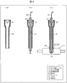
- FIG. 3 shows a schematic structure of the camera support tube 13 and the support tube joint 14.
- FIG. 3A is a perspective view of the camera support tube 13.
- the camera support tube 13 is a support tube that supports the camera unit 11 by being joined to the camera unit 11 inside the body in a state where the camera side cable 12 is pulled out of the body through the inside.
- One end of the camera support tube 13 is introduced into the body through a body wall 41 such as an abdominal wall.
- the end portion introduced into the body is joined to the camera unit 11 at the support tube joining portion 14.
- the camera support tube 13 is a cylindrical tube, and has a locking hole 123 (concave portion) at the end on the side to be introduced into the body.
- the camera support tube 13 is formed of a hard material.
- the material of the camera support tube 13 should be rigid enough to obtain a bonding strength capable of stably supporting the camera unit 11 and to fix the camera unit 11 in a desired position and orientation. Examples thereof include, but are not limited to, stainless steel, ceramics (fine ceramics), reinforced plastics, and the like.
- the camera support tube 13 Since the camera support tube 13 has a cylindrical shape, it is resistant to physical impact, and can be easily combined with a general cannula that is also a cylindrical tube.
- the camera support tube 13 may also be used as a puncture device with a sharpened tip or an obliquely cut shape like an injection needle.
- FIG. 3B is a cross-sectional view of the camera support tube 13 and the support tube joint 14, and FIG. 3C is a cross-sectional view showing a state in which the camera support tube 13 is inserted into the support tube joint 14.
- the camera support tube 13 has a tapered shape (tapered shape) at the tip of the camera support tube 123. The inner side does not get caught by the locking claw 23 of the support pipe joint 14, and when the camera support tube 13 is pushed in until the tip reaches the back of the support pipe joint 14, the locking hole 123 fits into the locking claw 23. It has become.
- the camera support tube 13 is not limited to the above structure. Both ends of the camera support tube 13 may have the same thickness.
- the camera support tube 13 may be tapered by reducing the wall thickness. it can.
- the inner diameter of the camera support tube 13 is made constant and only the outer diameter is changed (the outer shape is made smaller toward the tip), the instrument is halfway (narrower) when the instrument is inserted into the camera support tube. This is more desirable because it does not get stuck at the part where it is).
- the camera support tube 13 can be provided with a locking claw 523, and the support tube joining portion 14 can be provided with a locking hole 423.
- a groove-like recess 132 that goes around the outer surface as shown in FIGS. 12A and 12B is provided at the end of the camera support tube 13, and the inner surface of the support tube joint portion 14 goes around the inner surface. You may provide the hook-shaped convex part 232 to do. Further, a hook-like convex portion that goes around the outer surface may be provided at the end of the camera support tube 13, and a groove-like concave portion that goes around the inner surface may be provided at the supporting tube joint portion 14. By doing so, it is not necessary to perform the operation of matching the positions of the locking holes and the locking claws when inserting the camera support tube 13, it becomes easier to join the two and the fitting strength is increased, which is more desirable. .
- FIG. 4A is a cross-sectional view of the cannula 31, and FIG. 4B shows the camera support tube 13 shown in FIGS. 3A to 3D and the cannula shown in FIG.
- FIG. 4C is a cross-sectional view showing a joined state of the camera support tube 13 inserted into the cannula 31 and the camera unit 11 shown in FIG.
- the cannula 31 is a tubular device, and when one end (outside the body) is thicker than the other end (inside the body), the cannula 31 is inserted into the body wall 41. One end (outside the body) functions as a stopper. Thereby, the cannula 31 can be fixed to the body wall 41 without the camera support tube 13 falling out into the body.
- valve 37 which has a restoring property inside this one edge part (body outer side).
- the valve 37 has a valve structure at its central portion that is expanded when an external force is applied from the thick end (outside the body) to the narrow end (inside the body).
- the cannula 31 preferably has a small diameter in order to achieve minimal invasiveness. Specifically, the cannula 31 preferably has a diameter of 3 mm or less.
- the camera support tube 13 When joining the camera unit 11 to the camera support tube 13 in the body, first, as shown in FIG. 4 (b), the camera support tube 13 is inserted into the camera support tube 13 and the camera support tube 13 is passed through. The thin end of 13 is pressed against the thick end (outside the body) of the cannula 31, and the camera support tube 13 is cannulated until the thin end of the camera support tube 13 is exposed from the cannula 31. Insert into 31. At this time, the valve 37 is expanded by the camera support tube 13, and the camera support tube 13 is strongly tightened by the urging force due to the restoring property. As a result, the camera support tube 13 is fixed to the cannula 31. Note that the thick end (outside of the body) of the camera support tube 13 is also exposed from the cannula 31.
- the narrow end (inside of the body) of the camera support tube 13 is inserted into the concave support tube joint 14.
- the locking claw 23 is fitted in the locking hole 123, and the camera unit 11 and the camera support tube 13 are joined with high mechanical strength.
- the locking claw 23 and the locking hole 123 may have any shape as long as they can be fitted to each other, and an O-ring or the like can be used instead of the locking claw 23.
- the strength for fitting the camera support tube 13 and the support tube joint portion 14 is preferably set smaller than the adhesive strength of the adhesive fixing portion that adhesively fixes the camera side cable 12 and the camera unit 11. . This is because, when the camera support tube 13 is inserted into the support tube joint portion 14 of the camera unit 11, it is necessary to hold the cable, pull it to support it, and insert it while using the cable as a guide. If the fitting strength (joint strength) with the tube joint 14 is greater than the adhesive strength of the above-mentioned adhesive fixing portion, the adhesive fixing portion is damaged or the camera unit is pulled outwardly to damage the patient's body wall. This is because there is a risk that it may occur.
- the strength for fitting the camera support tube 13 and the support tube joint 14 is 30 N (Newton) or less, which is smaller than the adhesive strength of the adhesive fixing portion. Furthermore, as an optimal range, it is desirable to set the range from 3N to 6N. If it is set within this range, it can be fitted without applying excessive force when fitting, and the feeling that the camera support tube 13 has been fitted is transmitted to the hand, so that it can be safely done without continuously applying force to the camera. There is a special effect that it can be installed.
- the camera support tube 13 may be used as a puncture device by sharpening the tip or by cutting it into an obliquely cut shape like an injection needle.
- the camera side cable 12 is formed by a cable fastener 43 (cable holder) provided at the outer end 49 of the camera support tube 13 as shown in FIG.
- the camera support tube 13 and the camera unit 11 may be indirectly fixed by fixing the camera support tube 13 to the camera support tube 13.
- the cable fastener 43 may be the same body as the camera support tube 13 or a separate body.
- the cable holding strength of the cable fastener 43 that holds the camera side cable 12 on the camera support tube 13 is It is necessary that the bonding strength between the support tube 13 and the camera unit 11 is higher.
- the joint strength of the inserted camera support tube 13 is 3N to 6N
- the optimum range is preferably 5N to 50N.
- the side surfaces of the camera support tube 13 and the support tube joint 14 are formed of a material having good thermal conductivity. In this case, the heat dissipation from the camera unit 11 can be improved.
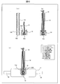
- FIG. 12 shows an example of a configuration in which the above-described bondability and heat dissipation are improved.
- 12A is a cross-sectional view of the camera support tube 13 and the support tube joint 14
- FIG. 12B is a cross-sectional view illustrating a state in which the camera support tube 13 is inserted into the support tube joint 14.
- FIG. 12C is a cross-sectional view showing a joined state of the camera support tube 13 and the camera unit 11 shown in FIG.
- a groove-like recess 132 that goes around the outer surface is provided at the end of the camera support tube 13 on the inner side of the camera support tube 13, and the corresponding support-tube joint portion having a concave shape is provided.
- 14 is provided with a hook-shaped convex portion 232 that goes around the inner surface.
- the concave support tube joint portion 14 has, for example, a heat conductive convex portion 14d made of a metal material having excellent thermal conductivity at the bottom thereof, and the camera side cable 12 is placed inside the heat conductive convex portion 14d. Bonded and fixed. In this case, the camera side cable 12 is pulled out from the heat transfer convex portion 14 d of the support tube joint portion 14.
- the adhesive fixing sealing fixing by pressure bonding, an adhesive, or an O-ring (O-ring) can be mentioned. As a result, it is possible to prevent water from entering the camera unit 11 from the adhesively fixed portion and mixing of foreign matters.
- the heat transfer convex portion 14d has a truncated cone shape that tapers toward the opening of the support tube joint portion 14, and the camera side cable 12 is passed through a hole formed in the axial direction thereof. In the hole, the camera side cable 12 and the heat conductive convex portion 14d are bonded and fixed.
- the inside (end portion space 166) has an inverse tapered shape (tip) corresponding to the truncated cone shape of the heat conductive convex portion 14d. The shape is such that the inner diameter increases as it approaches.
- the reverse tapered end space 166 of the camera support tube 13 leads to the heat transfer convex portion 14d of the support tube joint 14. Since it is guided, the camera support tube 13 can be easily inserted.
- the outer peripheral surface of the end of the camera support tube 13 contacts the inner wall of the support tube joint 14, and the end of the camera support tube 13 is Since the inner peripheral surface comes into contact with the heat transfer convex portion 14d of the support tube joint portion 14, the joint property between the two is enhanced, and the heat dissipation property of the heat transmitted from the camera unit 11 to the camera support tube 13 is further improved. A special effect is produced.
- FIGS. 5A to 5G are schematic views showing a method of installing the camera unit 11 in the body in the first embodiment
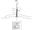
- FIG. 6 is a schematic view showing a use situation of the in-body monitoring camera system 1 in the first embodiment. It is.
- the operator opens a hole (port) for inserting forceps and an endoscope into the body cavity in the abdominal wall 41, and inserts trocars 32a to 32c into the ports.
- a port is opened at a position on the abdominal wall 41 where the entire organ including the affected part can be looked over, and the cannula 31 is inserted.
- the cannula 31 is inserted into the abdominal wall 41 by puncturing the obturator into the port while the needle-shaped obturator is passed through the cannula 31.
- the cannula 31 preferably has a short diameter in order to realize minimally invasiveness.
- the cannula 31 preferably has a diameter of 3 mm or less. After at least one of the trocars 32a to 32c and the cannula 31 is inserted, the operator sends gas into the body through the trocars 32a to 32c, and inflates the body cavity in advance to secure a space for inserting the instrument. .
- the operator inserts the endoscope 34 into the body cavity through the trocar 32c, and observes the inside of the body using the endoscope 34 while holding the camera with the forceps 33a.
- the unit 11 is inserted into the body cavity through the trocar 32b.
- the operator operates the forceps 33 a to move the camera unit 11 to the vicinity of the cannula 31 and inserts the forceps 33 b into the body cavity through the cannula 31.
- the operator pulls out the forceps 33b from the cannula 31 with the forceps 33b sandwiching the camera side cable 12, thereby leading the camera side cable 12 out of the body.
- the camera unit 11 (the gripping portion 22) is held by the forceps 33a.
- the operator inserts the forceps 33c into the body cavity through the trocar 32a, and the support tube joint 14 of the camera unit 11 and the opening of the cannula 31 are parallel and close to each other.
- the camera-side cable 12 led out of the body is passed through the camera support tube 13 and the camera support tube 13 is inserted. Is inserted into the cannula 31.
- the operator uses the end of the camera support tube 13 exposed from the cannula 31, using the camera side cable 12 as a guide, and the support tube joint 14 of the camera unit 11. (FIG. 1), and the camera support tube 13 and the camera unit 11 are joined.
- the camera support tube 13 When the camera support tube 13 is inserted into the support tube joint portion 14 of the camera unit 11, the camera support is more effective than the adhesive strength (for example, 30 N or more) of the adhesive fixing portion of the camera side cable 12 to the camera unit 11.
- the force required to fit the tube 13 and the support tube joint 14 (for example, 3N to 6N) is sufficiently small, so that the camera support tube 13 can be inserted safely by pulling while using the cable as a guide. And can be fitted.
- the operator pulls up the camera support tube 13 so that the inside of the body cavity can be imaged as wide as possible, and brings the camera unit 11 into contact with the inner end of the cannula 31. Since the camera support tube 13 is strongly tightened by the valve 37 (see FIG. 4) of the cannula 31, the camera support tube 13 and the camera unit 11 maintain this state.
- the camera side cable 12 and the device side cable 16 are joined using connectors 12a and 16a as shown in FIG.
- the local image of the treatment section is displayed on the display 118 by the endoscope control device 117, and the entire image of the organ 42 captured by the camera unit 11 is displayed on the display 18 by the camera unit control device 17.
- the cable diameter of the ultra-thin camera side cable 12 and the thick equipment side cable 16 and the thickness of the cable connector can be converted in stages, and the use of a thin cable with a relatively slow transmission speed can be used. Since it can be configured with the minimum necessary, the transmission speed can be increased and a high-resolution image can be obtained.
- the camera side cable 12 and the intermediate cable 15 are connected by fitting the camera side cable connector 15a and the first intermediate cable connector 15a of the intermediate cable 15 together.
- the device-side cable 16 and the intermediate cable 15 are connected by fitting the device-side cable connector 16 a and the second intermediate cable connector 15 b of the intermediate cable 15.
- the outer diameter of the camera-side cable 12 when the cable diameter and the thickness of the cable connector are converted in stages, “the outer diameter of the camera-side cable 12 ⁇ the outer diameter of the intermediate cable 15 ⁇ the outer diameter of the device-side cable 16” and “the camera-side cable 16” It is desirable that the outer diameter of the connector 12a ⁇ the outer diameter of the first intermediate cable connector 15a ⁇ the outer diameter of the second intermediate cable connector 15b ⁇ the outer diameter of the device-side cable connector 16a ”.
- the use of the intermediate cable 15 has a special effect that the clean field and the unclean field can be effectively separated at the time of surgery.
- the camera-side cable 12 to be inserted into the body is set to the minimum necessary length in order to facilitate the above-mentioned transmission speed and handling at the time of installation, and from there to the clean field beyond the clean field.
- the intermediate cable 15 that has been sterilized in advance is used. By doing in this way, fitting with the camera side cable connector 12a of the camera side cable 12 and the 1st intermediate
- the second intermediate cable connector 15b is fitted with the device-side cable connector 16a of the device-side cable 16 in the unclean field, becomes unclean, and is treated as a unclean device after the fitting. Therefore, it can be completely separated from the clean instrument side.
- the portion included in the “clean field” is sterilized to maintain cleanliness.
- the part included in “unclean field” is a part that has not been sterilized or entered the unclean field after sterilization.
- connection strength (fitting strength) when the camera side cable 12 and the intermediate cable 15 or the device side cable 16 are connected (fitted) with the connectors 12a and 15a or the connectors 12a and 16a is as follows. It is desirable to set it smaller than the adhesive strength of the adhesive fixing part that adheres and fixes the camera unit 11.
- the strength of connecting (fitting) the cables with the connectors 12a and 15a or the connectors 12a and 16a is desirably 30 N (Newton) or less, which is smaller than the adhesive strength of the adhesive fixing portion.
- the joint strength between the device-side cable connector 16a and the second intermediate cable connector 15b in the unclean field, and the device-side cable 16 by a cable connector (not shown) on the camera unit control device 17 side in the device-side cable 16 If the joint strength with the camera unit control device 17 is set larger than the joint strength between the camera side cable connector 12a and the first intermediate cable connector 15a (for example, 50N to 100N), an unexpected force is applied to the cable. Can be set such that the connection between the camera-side cable 12 and the intermediate cable 15 (combination of the camera-side cable connector 12a and the first intermediate cable connector 15a) in the clean field is always removed first.
- the intermediate cable 15 has a predetermined length from the joint between the camera-side cable connector 12a and the first intermediate cable connector 15a. If the part (clean part) and the first intermediate cable connector 15a touch the unclean field, it is safe because it may be replaced with a clean intermediate cable 15 (including the first intermediate cable connector 15a). Further, when the connector is composed of independent single parts and the connector touches the unclean field together with the side of the intermediate cable 15 in the clean field, the intermediate cable 15 and the connector are not cleaned. Replace it with something.
- the camera side cable 12 be sufficiently shorter than the length (about 1 m) obtained by adding the camera side cable 12 and the clean part.
- the camera side cable 12 is desirably less than half of the total length of the camera side cable 12 and the clean portion, that is, 50 cm at the longest. Thereby, it is possible to prevent the camera side cable 12 from entering the unclean field.
- the camera-side cable 12 is preferably smaller than the sum of the length of the camera support tube 13 and the length of the cannula 31 (tubular device) through which the camera support tube 13 passes.
- the case where the camera side cable 12 and the device side cable 16 are connected by the intermediate cable 15 has been described.
- the clean portion of the device-side cable 16 is a portion having a predetermined length from the joint portion between the camera-side cable connector 12a and the device-side cable connector 16a.
- the surgeon performs a treatment with the forceps 33a and the forceps 33c while magnifying and observing the work area (local area) on the display 118, while the display 18 is in a state outside the work area (movement of forceps and the like outside the work area) Bleeding residue, gauze residue, etc.).
- the camera unit 11 and the camera support tube 13 are joined with high mechanical strength, and the support force of the camera unit 11 is higher than the conventional one. Further, since the camera side cable 12 is led out of the body through the inside of the camera support tube 13, after the camera unit 11 and the camera support tube 13 are joined, a load is applied to the camera side cable 12, The side cable 12 is not exposed in the body and does not contact the abdominal wall 41. This increases the reliability of electrical connection between the camera-side cable 12 and the circuit board 19 (FIG. 2) (waterproofness and antifouling property of the connection portion). As described above, the highly reliable in-body monitoring camera system 1 can be realized.
- the surgeon can operate the camera support tube 13 according to the situation to change the direction (viewing direction) of the camera unit 11. Specifically, the direction of the camera unit 11 can be changed by tilting the camera support tube 13 using the elasticity of the abdominal wall 41. At this time, when the surgeon releases the hand from the camera support tube 13, the surgeon returns to the original direction by the elasticity of the abdominal wall 41, so that the operator's work efficiency can be improved. Moreover, since both the cannula 31 and the camera support tube 13 inserted therein are cylindrical tubes, the camera support tube 13 can be easily rotated in the circumferential direction. Thereby, the surgeon can change the direction of the camera unit 11 without imposing a burden on the abdominal wall 41.
- the camera support tube 13 is held by the cannula 31 so as to be movable in the longitudinal direction (stretching direction of the tube), the surgeon pushes the camera support tube 13 inward of the body or pulls it out of the body. It is also possible to change the imaging zoom without imposing a burden on the abdominal wall 41. From the above, the user-friendly surveillance camera system 1 can be realized.
- the cannula 31 and the camera support tube 13 are fixed by the valve 37 in the cannula 31, but when a general cannula not having the valve 37 is used, the cannula 31 and the camera support tube are used. 13 can be fixed with a tape. (Separation of camera unit 11 and camera support tube 13) Next, a method for separating the camera unit 11 and the camera support tube 13 will be described. First, the operator pulls the camera support tube 13 outwardly while holding the gripping portion 22 of the camera unit 11 in the body with the forceps 33a and the forceps 33c, and joins the camera support tube 13 to the support tube of the camera unit 11. Pull out from part 14.
- the operator pulls out the camera support tube 13 from the cannula 31, separates the camera support tube 13 and the camera side cable 12, and then removes the camera unit 11 and the camera side cable 12 from the trocar 32a or the trocar 32b. To derive. Alternatively, it may be withdrawn from a hole opened to withdraw the excised organ.
- the fitting strength between the camera support tube 13 and the support tube joining portion 14 is that the camera side cable 12 and the camera unit 11 are bonded and fixed. It is desirable to set it smaller than the adhesive strength of the adhesive fixing part. If the fitting strength (joint strength) between the camera support tube 13 and the support tube joint 14 is greater than the adhesive strength of the adhesive fixing portion, a large force is applied when the camera support tube 13 is removed from the camera unit 11. This is because there is a possibility that the adhesive fixing portion is broken or the camera unit is pulled in the direction of the outside of the body, thereby damaging the patient's body wall.
- the camera support tube 13 can be removed without applying excessive force, and the feeling that the camera support tube 13 has come off is at hand. Therefore, there is a special effect that it can be safely separated without continuously applying force.
- the camera side cable connector 12a passes through the body at the time of recovery, but there is no problem because cleanliness is maintained as described above.
- the heat generated in the solid-state image sensor 25 is transmitted to the circuit board 19 via the terminals of the solid-state image sensor 25. Then, the heat transferred to the circuit board 19 is transferred to the support tube joint 14 in contact with the circuit board 19. Alternatively, the heat transferred to the circuit board 19 is transferred to the support tube joint 14 that is away from the circuit board 19. Similarly, the heat generated in the lighting device 27 is transmitted to the support tube joint portion 14 via the circuit board 19.
- the support pipe joint 14 and the circuit board 19 are arranged so as to face each other. For this reason, the heat generated in the camera unit 11 is conducted to the support tube joint 14 through the circuit board 19. The heat is discharged from the camera unit 11 through the camera support tube 13.
- the circuit board 19 and the support tube joint 14 are preferably thermally connected by an adhesive, grease, or the like having high thermal conductivity.
- an adhesive, grease, or the like having high thermal conductivity functions as a heat conductor for transmitting heat generated in the solid-state imaging device 25 and the illumination device 27 to the support tube joint portion 14 via the circuit board 19.
- FIG. 7 is a schematic cross-sectional view of the camera unit 11 and the camera support tube 13 according to the second embodiment.
- the illumination device 27, the solid-state imaging device 25, and the control circuit 28, which are heat sources are thermally connected to the camera support tube 13 via the support tube joint portion 14 by a heat conductor 49 having high thermal conductivity.
- the heat generated from the illumination device 27, the solid-state imaging device 25, and the control circuit 28 can be directly transmitted to the support tube joint portion 14 without passing through the circuit board 19.
- the heat generated by the camera unit 11 can be exhausted more efficiently.
- heat conductor 49 heat radiating silicon rubber can be used, but is not limited thereto.
- the thermal resistance between the illumination device 27, the solid-state imaging device 25, the control circuit 28, and the camera support tube 13, which is a heat generating part, is preferably 20 ° C./W or less, although it depends on the heat generation amount of the heat source.
- the outer surface of the camera unit 11 contacts the abdominal wall 41, the outer surface needs to be 41 ° C. or lower.
- the support unit is joined from the heat generating portion of the camera unit 11. It is desirable that the thermal resistance up to the portion 14 is 20 ° C./W or less.
- the camera housing 21 can contact the abdominal wall 41. For this reason, it is necessary to make it difficult for the heat in the camera unit 11 to be transmitted to the abdominal wall 41 through the camera housing 21. Therefore, it is desirable that the thermal conductivity of the camera housing 21 (casing thermal conductivity) is lower than the thermal conductivity of the camera support tube 13 (support tube thermal conductivity).
- thermal conductivity of the camera support tube 13 is higher than the thermal conductivity of the camera housing 21, heat is transmitted to the camera support tube 13 prior to the camera housing 21, and heat is released from the camera support tube 13. The rise in heat of the casing 21 can be suppressed.
- the camera housing 21 is suitably composed of a resin such as polycarbonate.
- the thermal conductivity of the resin is around 0.2 W / (m ⁇ K).
- the material of the camera housing 21 is not limited to the above.
- the material of the camera support tube 13 and the support tube joint 14 is preferably a material having high thermal conductivity.
- the material for example, Ag, Cu, Al, SUS, brass, ceramic material, or the like can be used.
- the materials of the camera support tube 13 and the support tube joint 14 are not limited to those described above.
- the thermal conductivity of the camera support tube 13 and the support tube joint 14 needs to be higher than the thermal conductivity of the camera housing 21 as described above.
- the thermal conductivity is at least 1.0 W / (m ⁇ K), which is five times the thermal conductivity of 0.2 W / (m ⁇ K) of the resin constituting the camera housing 21 (high thermal conductivity). Rate) is desirable.
- the camera support tube 13 and the support tube joint portion 14 may be made of a plurality of materials.
- a locking hole (concave portion) is provided on the side surface of the camera support tube and a locking claw (convex portion) is provided on the side surface of the support tube joint portion.
- At least one may be made of an elastic material such as a resin, and the other may be made of a hard material such as a metal.
- the locking claws 23 and the locking claws 523 may be made of an elastic material such as resin.
- the elastic claw 23 (elastic material) disposed at the joint portion is slightly narrowed through the deformed portion while the elastic material is deformed.
- the joint strength is improved because it is firmly fitted.
- an elastic material may be formed on at least one of the support tube and the uneven portion of the joint. In addition, by doing so, the fitted feel is transmitted to the hand, so that the operating surgeon feels the fit and can recognize that the fit has been made, so continue to apply force unnecessarily There is also an advantage that there is no.
- the sides of the support tube and its joint are made of a material with good thermal conductivity to improve heat dissipation from the camera unit, and the joint strength is increased by using an elastic material only on the convex part of the joint, and fitting is performed. If a plurality of materials having different properties are added, such as adding a function that feels the response to the above, it is possible to achieve a plurality of required performances such as bondability and heat dissipation.
- the locking claw may be made of a hard material such as a metal
- the portion including the locking hole may be made of an elastic material such as a resin.
- FIG. 8 is a schematic cross-sectional view of the camera unit 11 and the camera support tube 13 according to the third embodiment.
- a heat sink 43 (an in-body monitoring camera heat exhausting part, a heat dissipation amount increasing part) is provided at a position exposed to the outside of the body from the cannula 31 of the camera support tube 13. The heat sink 43 dissipates heat generated from the camera unit 11 and transmitted through the camera support tube 13.
- the heat sink 43 may be molded integrally with the camera support tube 13 or may be attached to the camera support tube 13 after the camera support tube 13 is coupled to the camera unit 11. Similarly to the camera support tube 13, the heat sink 43 is preferably made of a material having a higher thermal conductivity than the camera housing 21.
- the heat sink 43 By attaching the heat sink 43 to the camera support tube 13, the surface area for discharging heat from the camera support tube 13 increases. For this reason, the amount of heat discharged from the camera support tube 13 into the air increases. As a result, the heat dissipation efficiency of the camera unit 11 is improved.
- a heat dissipating fan 46 for increasing the amount of air moving in contact with the heat sink 43.
- the heat radiating fan 46 blows air to the heat sink 43 or discharges air near the heat sink 43.
- cooling is performed so as to include the heat sink 43 (heat radiating portion) that releases heat transferred from the camera support tube 13 to the outside air and the heat radiating fan 46 (heat radiation amount promoting portion) that blows air to the heat sink 43.
- a system 77 is configured.
- FIG. 9 is a schematic cross-sectional view of the camera unit 11 and the camera support tube 13 according to the fourth embodiment.
- a low temperature material mounting plate 44 is attached to a portion of the camera support tube 13 exposed from the cannula 31 to the outside of the body so as to be in contact with a wide area.
- the low-temperature material mounting plate 44 is provided with the low-temperature material 40 (in-body monitoring camera heat discharge unit, conduction heat absorption unit).
- the low temperature material 40 absorbs heat generated from the camera unit 11 and conducted to the camera support tube 13 via the low temperature material mounting plate 44.
- the low-temperature material attachment plate (coolant attachment plate) 44 and the low-temperature material 40 (coolant, heat absorbing portion) that absorbs heat transmitted from the camera support tube 13 through the low-temperature material attachment plate 44.
- the low-temperature material 40 a case where frozen ice-cooling material and dry ice are put can be used. However, it is not limited to the above as long as it absorbs heat.
- FIG. 10 is a schematic cross-sectional view of the camera unit 11 and the camera support tube 13 according to the fifth embodiment.
- a low temperature material mounting plate 44 is attached to a portion of the camera support tube 13 exposed from the cannula 31 to the outside of the body so as to be in contact with a wide area.
- a Peltier element 45 is disposed between the heat sink 43 and the low-temperature material mounting plate 44. The Peltier element 45 moves the heat that has passed from the camera unit 11 through the camera support tube 13 to the heat sink 43.
- the heat sink 43 is provided with a heat radiating fan 46. The heat radiating fan 46 discharges the heat moved to the heat sink 43 into the air.
- the heat generated in the camera unit 11 is transmitted to the low temperature material mounting plate 44 through the camera support tube 13.
- the Peltier element 45 absorbs heat on the low temperature material mounting plate 44 side, and is supplied with voltage by Peltier element cables 47 and 48 so that heat is generated on the heat sink 43 side.
- the heat transmitted from the camera support tube 13 is moved from the low-temperature material mounting plate 44 to the heat sink 43 by the Peltier element 45.
- the heat transferred to the heat sink 43 is discharged into the air by the heat radiating fan 46 attached to the heat sink 43. For this reason, heat can be efficiently radiated. As described above, in FIG.
- the cooling system 77 is configured to include a heat sink 43 (heat radiating portion) that releases heat from the air 45 to the outside air and a heat radiating fan (heat radiating promotion portion) that blows air to the heat sink 43.
- the said embodiment has shown the case where the thermal radiation fan 46 is attached to the heat sink 43, this invention is not limited to this. It is also possible to cool the heat sink 43 by natural convection without attaching the heat radiating fan 46.
- the cooling system may be configured to send room temperature air or cool air below room temperature to the external part of the camera support tube, or connect the cooling device using power and the camera support tube with a heat transfer body. Such a configuration may be used.
- An in-vivo monitoring camera system 1 includes a support tube (camera support tube 13) having one end introduced into the body, and an in-vivo monitoring camera (camera) joined to the support tube in the body. Unit 11), a joint (support pipe joint 14) for joining the in-vivo monitoring camera and the support tube, and a cable (camera side) connected to the in-vivo monitoring camera and drawn out of the body through the support tube
- An in-body monitoring camera system comprising a cable 12) and a control system (camera unit control device 17) that is external to the body and is connected to the cable and includes at least a display device (display 18).
- An internal monitoring camera heat exhausting unit low temperature material 40, heat sink 43, heat radiating fan 46 for exhausting the generated heat to the outside of the body through the support tube. Eteiru.
- the heat generated from the internal monitoring camera is exhausted outside the body through the support tube by the internal monitoring camera heat exhausting unit.
- One end of the support tube is introduced into the body.
- the internal monitoring camera system 1 according to aspect 2 of the present invention is the internal heat monitoring camera system 1 according to aspect 1, in which the internal monitoring camera heat discharge unit absorbs heat generated from the internal monitoring camera and conducted to the support tube.
- Part (low temperature material 40) may be included.
- the heat generated from the internal monitoring camera and conducted to the support tube is absorbed, so that the heat generated inside the internal monitoring camera can be efficiently discharged.
- the conduction heat absorption unit may include a low-temperature material 40 that absorbs the conducted heat.
- the low temperature material absorbs the heat generated from the in-vivo monitoring camera and conducted to the support tube, so that the heat generated inside the in-body monitoring camera can be efficiently discharged.
- the internal monitoring camera system 1 according to aspect 4 of the present invention is the internal monitoring camera system 1 according to aspect 1, wherein the internal monitoring camera heat exhausting unit increases the heat dissipation amount from the support tube to the air (heat sink 43, Peltier).
- An element 45 and a heat dissipation fan 46) may be included.
- the amount of heat generated from the in-vivo monitoring camera and conducted to the support tube is increased in the air, so that the heat from the in-body monitoring camera can be efficiently discharged.
- the heat dissipation amount increasing unit may include a heat sink 43 that dissipates heat from the support tube.
- the heat generated from the in-vivo monitoring camera and conducted to the support tube is dissipated by the heat sink, the heat from the in-body monitoring camera can be efficiently discharged.
- the heat dissipation amount increasing unit may further include a heat dissipation fan 46 for increasing the amount of movement of air in contact with the heat sink.
- the heat dissipation amount increasing portion is disposed between the heat sink and the support tube, and heat from the support tube is transferred to the heat sink.
- a Peltier element 45 may be further included.
- the heat from the support tube is transferred to the heat sink by the Peltier element, the heat transmitted from the in-body monitoring camera to the support tube can be efficiently discharged.
- the heat dissipation amount increasing unit may further include a heat dissipation fan for discharging the heat transferred to the heat sink into the air.
- the heat transferred to the heat sink is discharged into the air by the heat radiating fan, the heat transferred to the heat sink from the in-body monitoring camera via the support tube and the Peltier element is efficiently It can be discharged.
- the internal monitoring camera system according to aspect 9 of the present invention is the internal monitoring camera system according to aspect 1, in which the internal monitoring camera has an imaging housing that can contact the body wall, and the support tube thermal conductivity of the material constituting the support tube Is preferably higher than the casing thermal conductivity of the material of the imaging casing.
- the support tube thermal conductivity of the material constituting the support tube is higher than the housing thermal conductivity of the imaging housing material, the heat generated from the in-vivo monitoring camera is The end portion of the support tube is easily transmitted to the support tube introduced into the body, and the heat can be efficiently discharged through the other end portion of the support tube.
- the support tube thermal conductivity is preferably 5 times or more of the housing thermal conductivity.
- the said support tube thermal conductivity is 5 times or more of the said housing thermal conductivity, the said support tube by which the one end part is introduce
- the in-vivo monitoring camera system according to aspect 11 of the present invention is the in-embodiment monitoring camera system according to aspect 1, in which the in-vivo monitoring camera illuminates the inside of the body, an image sensor that images the inside of the body illuminated by the illuminating device, and the illuminating device.
- a heat conductor that thermally connects the image sensor and the joint may be included.
- the said illuminating device, the said image pick-up element, and the said junction part are thermally connected by a heat conductor. For this reason, the heat generated from the illuminating device and the image sensor is easily transmitted to the support tube having one end introduced into the body. As a result, the heat generated from the illumination device and the imaging element can be efficiently discharged through the other end of the support tube.
- the in-vivo surveillance camera system according to aspect 12 of the present invention is the above-described aspect 11, wherein the thermal resistance between the illumination device and the joint and between the imaging element and the joint is 20 ° C./W or less. It is preferable that
- the thermal resistance between the said illuminating device and the said junction part and between the said image pick-up element and the said junction part is 20 degrees C / W or less
- the said illuminating device and the said image pick-up element Are more thermally connected to the joint.
- the heat generated from the illumination device and the image sensor is more easily transmitted by the support tube having one end portion introduced into the body.
- the heat generated from the illumination device and the image sensor can be more efficiently discharged through the other end of the support tube.
- An in-vivo surveillance camera system includes a support tube having one end introduced into the body, an imaging unit joined to the support tube and the body, the imaging unit, and the support tube.
- a joint connected to the imaging unit, a cable drawn out of the body through the support tube, a control system outside the body, connected to the cable, and including at least a display device, and the imaging unit And a cooling system that cools the support tube through which heat is transmitted.
- the cooling system includes a heat absorption part that absorbs heat transmitted from the support tube.
- the cooling system includes a heat radiating portion that releases heat transferred from the support tube to the outside air.
- the cooling system includes a heat dissipation promoting unit that promotes release of heat to the outside air by the heat dissipation unit.
- the thermal conductivity of the material used for the support tube is the heat of the material used for the housing of the imaging unit.
- the configuration is higher than the conductivity.
- An in-vivo monitoring camera system includes a support tube having one end introduced into the body, an imaging unit joined to the support tube and the body, the imaging unit, and the support tube.
- a heat generating member for example, a lighting device, an image sensor, and a control circuit
- the support tube or the joint is used for an elastic material and a casing of the imaging unit. It is composed of a combination with a high thermal conductivity material having a higher thermal conductivity than the material to be obtained.
- the support tube is made of a high thermal conductivity material having a higher thermal conductivity than the material used for the housing of the imaging unit
- the joint portion is composed of a combination of an elastic material and a high thermal conductivity material having a higher thermal conductivity than the material used for the housing of the imaging unit.
- the in-vivo monitoring camera system according to aspect 21 of the present invention is the body monitoring camera system according to any one of the aspects 13 to 20, wherein the joint having a concave shape has a heat transfer convex part having heat transfer at the bottom thereof.
- the joint having a concave shape has a heat transfer convex part having heat transfer at the bottom thereof.
- the heat conductive convex portion is configured to taper as approaching the opening of the joint portion.
- the in-vivo surveillance camera system includes a cable holder that holds the cable and fixes the cable to the support tube in any one of the aspects 13 to 22, and the cable holding strength of the cable holder is The structure is larger than the joint strength between the support tube and the joint.
- the bonding strength is in a range of 3N to 6N.
- the in-vivo surveillance camera system includes a cable holder that holds the cable and fixes the cable to the support tube in any one of the aspects 13 to 24, and the cable holding strength of the cable holder is
- the configuration is in the range of 5N to 50N.
- a high thermal conductivity material having a higher thermal conductivity than the material used for the housing of the imaging unit is used for each of the support tube and the joint.
- the present invention can be used for an in-vivo monitoring camera system including an in-vivo monitoring camera that can be introduced into the body.
- the internal monitoring camera system of the present invention is suitable for endoscopic surgery and the like.
Landscapes
- Health & Medical Sciences (AREA)
- Life Sciences & Earth Sciences (AREA)
- Surgery (AREA)
- Engineering & Computer Science (AREA)
- Physics & Mathematics (AREA)
- Optics & Photonics (AREA)
- Biomedical Technology (AREA)
- Veterinary Medicine (AREA)
- Biophysics (AREA)
- Pathology (AREA)
- Radiology & Medical Imaging (AREA)
- Nuclear Medicine, Radiotherapy & Molecular Imaging (AREA)
- Public Health (AREA)
- Heart & Thoracic Surgery (AREA)
- Medical Informatics (AREA)
- Molecular Biology (AREA)
- Animal Behavior & Ethology (AREA)
- General Health & Medical Sciences (AREA)
- Multimedia (AREA)
- Signal Processing (AREA)
- Mechanical Engineering (AREA)
- Microelectronics & Electronic Packaging (AREA)
- Astronomy & Astrophysics (AREA)
- General Physics & Mathematics (AREA)
- Endoscopes (AREA)
- Instruments For Viewing The Inside Of Hollow Bodies (AREA)
Abstract
Description
(体内監視カメラシステム1の構成)
図1は、実施形態1の体内監視カメラシステム1の構成を示す模式図である。図1に示すように、体内監視カメラシステム1は、カメラユニット11(撮像部)と、一端がカメラユニット11に接続されたカメラ側ケーブル12と、カメラ支持管13(支持管)と、カメラユニット制御機器17およびディスプレイ18(表示装置)を含む制御システムと、一端がカメラユニット制御機器17に接続された機器側ケーブル16とを備える。なお、カメラ側ケーブル12の他端に設けられたカメラ側ケーブルコネクタ12aと機器側ケーブル16の他端に設けられた機器側ケーブルコネクタ16aとを嵌合することでカメラユニット11と制御システム3とが電気的に接続される。なお、以下では、カメラ側ケーブルコネクタ12aをコネクタ12aと、機器側ケーブルコネクタ16aをコネクタ16aと略記することがある。
図2(a)は実施の形態1のカメラユニット11の模式的断面図であり、図2(b)はその上面図である。図2(a)(b)に示すように、カメラユニット11では、カメラ筐体21(撮像筐体)内に、回路基板19と、回路基板19に接続する、固体撮像素子25、制御回路28、および照明装置27と、レンズ26とが設けられている。カメラ筐体21の上面には、凹形状の支持管接合部14が設けられている。支持管接合部14は、円形開口の穴構造であり、その内壁に係止爪23(凸部)が設けられている。また、カメラ筐体21の対向する両側面それぞれから握持部22が突出している。握持部22は、鉗子を用いて、カメラユニット11を体内に導入する際に把持されたり、カメラユニット11およびカメラ支持管13の接合時に、カメラユニット11の上面(支持管接合部14が設けられた面)がカメラ支持管13の端部に向かい合うように把持されたりする。
図3に、カメラ支持管13および支持管接合部14の概略構造を示す。図3(a)は、カメラ支持管13の斜視図である。カメラ支持管13は、カメラ側ケーブル12を内部に通して体外へ引き出した状態で、体内でカメラユニット11と接合されることで、カメラユニット11を支持する支持管である。カメラ支持管13は、腹壁等の体壁41を通じて、その一方の端部が体内に導入される。体内に導入された端部は、支持管接合部14にてカメラユニット11と接合される。
図4(a)は、カニューレ31の断面図であり、図4の(b)は、図3の(a)~(d)に示すカメラ支持管13を、図4の(a)に示すカニューレ31に挿入した状態を示す断面図であり、図4の(c)は、カニューレ31に挿入されたカメラ支持管13と図2に示すカメラユニット11との接合状態を示す断面図である。
(実施形態1における体内監視カメラシステム1の使用方法と効果)
図5(a)~(g)は、実施の形態1におけるカメラユニット11の体内設置方法を示す模式図であり、図6は、実施形態1における体内監視カメラシステム1の使用状況を示す模式図である。
(カメラユニット11とカメラ支持管13との分離)
次に、カメラユニット11とカメラ支持管13とを分離させる方法について説明する。まず、術者は、体内のカメラユニット11の握持部22を鉗子33aおよび鉗子33cにて把持した状態でカメラ支持管13を体外方向に引っ張り、カメラ支持管13をカメラユニット11の支持管接合部14から引き抜く。次いで、術者は、カメラ支持管13をカニューレ31から引き抜いてカメラ支持管13とカメラ側ケーブル12とを分離させた後、トロッカー32aまたはトロッカー32bから、カメラユニット11およびカメラ側ケーブル12を体外に導出する。あるいは、切除した臓器を引き出すために開口した孔から引き出してもかまわない。
次に、腹壁41に固定されるカメラユニット11(体内監視カメラ)の放熱について説明する。図2で前述したカメラユニット11に設けられた各部品で発生した熱は、下記の様に伝導する。
カメラ筐体21は、ポリカーボネイトなどの樹脂により構成することが適している。当該樹脂の熱伝導率は、0.2W/(m・K)前後である。但し、カメラ筺体21の材料は前記のものに限定されるものではない。
また、カメラ支持管13及び支持管接合部14は、それぞれ複数の材料で構成してもかまわない。実施の形態1では、カメラ支持管の側面に係止孔(凹部)を設け、支持管接合部の側面に係止爪(凸部)を設けているが、支持管凹部と接合部凸部の少なくとも一方を樹脂などの弾性を持った材料、他方を金属等の硬質材料で構成してもよい。例えば、上記の係止爪23や係止爪523は、樹脂などの弾性を持った材料で構成してもよい。
また、このようにすることによって、嵌め込んだ感触が手元に伝わるので、操作している術者は嵌合した手ごたえを感じ、嵌合できたことが認識できので、むやみに力を加え続けることがないといった利点もある。
図8は、実施形態3に係るカメラユニット11及びカメラ支持管13の模式的断面図である。カメラ支持管13のカニューレ31から体外側に露出した箇所に、ヒートシンク43(体内監視カメラ熱排出部、放熱量増加部)が設けられている。ヒートシンク43は、カメラユニット11から発生してカメラ支持管13を伝熱してきた熱を放散する。
図9は、実施形態4に係るカメラユニット11及びカメラ支持管13の模式的断面図である。カメラ支持管13のカニューレ31から体外側に露出した箇所に、広い面積で接するように低温材料取り付け板44が取り付けられている。そして、低温材料取り付け板44に低温材料40(体内監視カメラ熱排出部、伝導熱吸収部)が設けられる。低温材料40は、カメラユニット11から発生してカメラ支持管13に伝導された熱を、低温材料取り付け板44を介して吸収する。このように、図9においては、低温材料取り付け板(冷却材取り付け板)44と、カメラ支持管13から低温材料取り付け板44を介して伝わった熱を吸収する低温材料40(冷却材、吸熱部)とを含むように冷却システム77が構成される。
図10は、実施形態5に係るカメラユニット11及びカメラ支持管13の模式的断面図である。カメラ支持管13のカニューレ31から体外側に露出した箇所に、広い面積で接するように低温材料取り付け板44が取り付けられている。そして、ヒートシンク43と低温材料取り付け板44との間にペルチェ素子45が配置されている。ペルチェ素子45は、カメラユニット11からカメラ支持管13を通ってきた熱をヒートシンク43に移動させる。ヒートシンク43には、放熱ファン46が設けられている。放熱ファン46は、ヒートシンク43に移動した熱を空気中に排出する。
なお、冷却システムは、カメラ支持管の体外部分に室温の風または室温未満の冷風を送るような構成であってもよいし、電力を用いた冷却装置とカメラ支持管とを伝熱体で繋ぐような構成であっても構わない。
本発明の態様1に係る体内監視カメラシステム1は、一方の端部が体内に導入される支持管(カメラ支持管13)と、上記支持管と前記体内にて接合される体内監視カメラ(カメラユニット11)と、上記体内監視カメラと上記支持管とを接合する接合部(支持管接合部14)と、上記体内監視カメラに接続され、上記支持管を通って体外へ引き出されるケーブル(カメラ側ケーブル12)と、体外にあり、上記ケーブルに接続され、少なくとも表示装置(ディスプレイ18)を含む制御システム(カメラユニット制御機器17)と、を備える体内監視カメラシステムであって、上記体内監視カメラから発生する熱を、上記支持管を介して前記体外へ排出する体内監視カメラ熱排出部(低温材料40、ヒートシンク43、放熱ファン46)を備えている。
本発明の態様20に係る体内監視カメラシステムは、上記態様19において、上記支持管は、上記撮像部の筐体に用いられる材料よりも高い熱伝導率を持つ高熱伝導率材で構成され、上記接合部は、弾性材と、上記撮像部の筐体に用いられる材料よりも高い熱伝導率を持つ高熱伝導率材との組み合わせで構成される。
11 カメラユニット(体内監視カメラ)
12 カメラ側ケーブル(ケーブル)
13 カメラ支持管(支持管)
14 支持管接合部(接合部)
17 カメラユニット制御機器(制御システム)
18 ディスプレイ(表示装置)
21 カメラ筐体(撮像筐体)
27 照明装置
25 固体撮像素子(撮像素子)
40 低温材料(吸熱部、体内監視カメラ熱排出部、伝導熱吸収部)
43 ヒートシンク(放熱部、体内監視カメラ熱排出部、放熱量増加部)
45 ペルチェ素子(放熱促進部、体内監視カメラ熱排出部、放熱量増加部)
46 放熱ファン(放熱促進部、体内監視カメラ熱排出部、放熱量増加部)
49 導熱体
77 冷却システム
Claims (14)
- 一方の端部が体内に導入される支持管と、
上記支持管と前記体内にて接合される撮像部と、
上記撮像部と上記支持管とを接合する接合部と、
上記撮像部に接続され、上記支持管を通って体外へ引き出されるケーブルと、
体外にあり、上記ケーブルに接続され、少なくとも表示装置を含む制御システムと、
上記撮像部の熱が伝わる上記支持管を冷却する冷却システムとを備えることを特徴とする体内監視カメラシステム。 - 上記冷却システムは、上記支持管から伝わった熱を吸収する吸熱部を含むことを特徴とする請求項1に記載の体内監視カメラシステム。
- 上記冷却システムは、上記支持管から伝わった熱を外気に放出する放熱部を含むことを特徴とする請求項1に記載の体内監視カメラシステム。
- 上記冷却システムは、上記放熱部による外部への熱の放出を促進させる放熱促進部を備えることを特徴とする請求項3に記載の体内監視カメラシステム。
- 上記支持管に用いられる材料の熱伝導率は、上記撮像部の筐体に用いられる材料の熱伝導率よりも高いことを特徴とする請求項1から4のいずれか1項に記載の体内監視カメラシステム。
- 一方の端部が体内に導入される支持管と、
上記支持管と前記体内にて接合される撮像部と、
上記撮像部と上記支持管とを接合する接合部と、
上記撮像部に接続され、上記支持管を通って体外へ引き出されるケーブルと、
体外にあり、上記ケーブルに接続され、少なくとも表示装置を含む制御システムと、
上記撮像部内の発熱部材で生じた熱を上記接合部に伝える導熱体とを備えることを特徴とする体内監視カメラシステム。 - 上記支持管または上記接合部は、弾性材と、上記撮像部の筐体に用いられる材料よりも高い熱伝導率を持つ高熱伝導率材との組み合わせで構成されることを特徴とする請求項1から6のいずれか1項に記載の体内監視カメラシステム。
- 上記支持管は、上記撮像部の筐体に用いられる材料よりも高い熱伝導率を持つ高熱伝導率材で構成され、上記接合部は、弾性材と、上記撮像部の筐体に用いられる材料よりも高い熱伝導率を持つ高熱伝導率材との組み合わせで構成されることを特徴とする請求項7に記載の体内監視カメラシステム。
- 凹形状である上記接合部は、その底部に伝熱性を有する伝熱性凸部を有し、上記撮像部および上記支持管の接合時に、上記支持管の内周面と上記伝熱性凸部とが接触することを特徴とする請求項1から8のいずれか1項に記載の体内監視カメラシステム。
- 上記伝熱性凸部は、上記接合部の開口に近づくにつれて先細りする形状であることを特徴とする請求項9に記載の体内監視カメラシステム。
- 上記ケーブルを保持して上記支持管に固定するケーブルホルダを備え、上記ケーブルホルダのケーブル保持強度は、上記支持管と上記接合部の接合強度より大きいことを特徴とする請求項1から10のいずれか1項に記載の体内監視カメラシステム。
- 上記接合強度は、3Nから6Nの範囲であることを特徴とする請求項11に記載の体内監視カメラシステム。
- 上記ケーブルを保持して上記支持管に固定するケーブルホルダを備え、上記ケーブルホルダのケーブル保持強度は、5Nから50Nの範囲であることを特徴とする請求項1から12のいずれか1項に記載の体内監視カメラシステム。
- 上記撮像部の筐体に用いられる材料よりも高い熱伝導率を持つ高熱伝導率材が、上記支持管および接合部それぞれに用いられている請求項1~13のいずれか1項に記載の体内監視カメラシステムの支持管であって、
上記撮像部との接合時に、上記支持管の高熱伝導率材が、上記接合部の高熱伝導率材に接触することを特徴とする体内監視カメラシステムの支持管。
Priority Applications (3)
| Application Number | Priority Date | Filing Date | Title |
|---|---|---|---|
| JP2015550958A JP5976957B2 (ja) | 2013-11-26 | 2014-11-26 | 体内監視カメラシステム、体内監視カメラシステムの支持管 |
| US15/031,777 US10085626B2 (en) | 2013-11-26 | 2014-11-26 | In-vivo monitoring camera system, and support tube for in-vivo monitoring camera system |
| US16/101,560 US20180368669A1 (en) | 2013-11-26 | 2018-08-13 | In-vivo imaging apparatus, and support member for in-vivo imaging apparatus |
Applications Claiming Priority (2)
| Application Number | Priority Date | Filing Date | Title |
|---|---|---|---|
| JP2013-244151 | 2013-11-26 | ||
| JP2013244151 | 2013-11-26 |
Related Child Applications (2)
| Application Number | Title | Priority Date | Filing Date |
|---|---|---|---|
| US15/031,777 A-371-Of-International US10085626B2 (en) | 2013-11-26 | 2014-11-26 | In-vivo monitoring camera system, and support tube for in-vivo monitoring camera system |
| US16/101,560 Continuation US20180368669A1 (en) | 2013-11-26 | 2018-08-13 | In-vivo imaging apparatus, and support member for in-vivo imaging apparatus |
Publications (1)
| Publication Number | Publication Date |
|---|---|
| WO2015080148A1 true WO2015080148A1 (ja) | 2015-06-04 |
Family
ID=53199087
Family Applications (1)
| Application Number | Title | Priority Date | Filing Date |
|---|---|---|---|
| PCT/JP2014/081225 Ceased WO2015080148A1 (ja) | 2013-11-26 | 2014-11-26 | 体内監視カメラシステム、体内監視カメラシステムの支持管 |
Country Status (3)
| Country | Link |
|---|---|
| US (2) | US10085626B2 (ja) |
| JP (2) | JP5976957B2 (ja) |
| WO (1) | WO2015080148A1 (ja) |
Cited By (6)
| Publication number | Priority date | Publication date | Assignee | Title |
|---|---|---|---|---|
| JP2019500097A (ja) * | 2015-12-03 | 2019-01-10 | ゼノコア インコーポレイテッド | 医療用ボアスコープならびに関連する方法およびシステム |
| US10441154B2 (en) | 2014-01-16 | 2019-10-15 | Sharp Kabushiki Kaisha | Camera system for monitoring inside of body and auxiliary device and method for installing imaging apparatus for monitoring inside of body |
| US10542879B2 (en) | 2014-03-31 | 2020-01-28 | Sharp Kabushiki Kaisha | In-body monitoring camera system and camera unit with gripping portion |
| JP2020520694A (ja) * | 2017-05-25 | 2020-07-16 | コヴィディエン リミテッド パートナーシップ | ロボット手術システムおよびロボット手術システムのコンポーネントを覆うためのドレープ |
| US10893795B2 (en) | 2014-01-23 | 2021-01-19 | Sharp Kabushiki Kaisha | Camera system for monitoring inside of body and auxiliary tool set |
| JP2024503714A (ja) * | 2021-01-25 | 2024-01-26 | バード・ペリフェラル・バスキュラー・インコーポレーテッド | 冷やされた生検針を有する生検システムおよび装置 |
Families Citing this family (8)
| Publication number | Priority date | Publication date | Assignee | Title |
|---|---|---|---|---|
| JP5976957B2 (ja) * | 2013-11-26 | 2016-08-24 | シャープ株式会社 | 体内監視カメラシステム、体内監視カメラシステムの支持管 |
| KR102265326B1 (ko) * | 2014-02-03 | 2021-06-15 | 삼성전자 주식회사 | 이미지 촬영장치 및 방법 |
| DE102016111960A1 (de) * | 2016-06-30 | 2018-01-04 | Karl Storz Gmbh & Co. Kg | Vorrichtung für die Videoendoskopie |
| JP2018148811A (ja) * | 2017-03-10 | 2018-09-27 | オリンパス株式会社 | 観察装置及び通信ケーブル |
| CN110520029A (zh) * | 2017-05-09 | 2019-11-29 | 直观外科手术操作公司 | 用于提高医疗器械的散热能力的设备和方法 |
| EP4280930A1 (en) * | 2021-01-25 | 2023-11-29 | Tympany Medical Limited | Medical instruments |
| EP4032457B1 (en) * | 2021-01-25 | 2025-07-02 | Tympany Medical Limited | Medical instruments |
| US20250064311A1 (en) * | 2023-08-24 | 2025-02-27 | Boston Scientific Scimed, Inc. | Medical assemblies, devices, systems, and related methods for dissipating heat |
Citations (6)
| Publication number | Priority date | Publication date | Assignee | Title |
|---|---|---|---|---|
| JPH0534605A (ja) * | 1991-07-29 | 1993-02-12 | Olympus Optical Co Ltd | 内視鏡用外付テレビカメラ |
| JP2005319086A (ja) * | 2004-05-10 | 2005-11-17 | Fujinon Corp | 体腔内観察システム |
| JP2008080117A (ja) * | 2006-09-01 | 2008-04-10 | Sony Corp | 内視鏡カメラおよび内視鏡カメラシステム |
| JP2009072368A (ja) * | 2007-09-20 | 2009-04-09 | Olympus Medical Systems Corp | 医療装置 |
| JP2009082700A (ja) * | 2007-09-10 | 2009-04-23 | Univ Of Yamanashi | 医療装置及び生体組織冷凍採取装置 |
| JP2013538102A (ja) * | 2010-09-19 | 2013-10-10 | イーオーエヌ サージカル エルティーディ. | マイクロ腹腔鏡デバイス及びその配置 |
Family Cites Families (16)
| Publication number | Priority date | Publication date | Assignee | Title |
|---|---|---|---|---|
| US8118732B2 (en) * | 2003-04-01 | 2012-02-21 | Boston Scientific Scimed, Inc. | Force feedback control system for video endoscope |
| US7591783B2 (en) * | 2003-04-01 | 2009-09-22 | Boston Scientific Scimed, Inc. | Articulation joint for video endoscope |
| US7578786B2 (en) * | 2003-04-01 | 2009-08-25 | Boston Scientific Scimed, Inc. | Video endoscope |
| US20060074307A1 (en) | 2004-05-10 | 2006-04-06 | Tatsuo Igarashi | Body cavity diagnostic system |
| JP5154144B2 (ja) * | 2007-05-31 | 2013-02-27 | 富士フイルム株式会社 | 超音波内視鏡及び超音波内視鏡装置 |
| JP5154146B2 (ja) * | 2007-06-05 | 2013-02-27 | 富士フイルム株式会社 | 超音波内視鏡及び超音波内視鏡装置 |
| JP4472727B2 (ja) | 2007-06-14 | 2010-06-02 | オリンパスメディカルシステムズ株式会社 | 内視鏡装置 |
| JP5329065B2 (ja) * | 2007-09-28 | 2013-10-30 | 富士フイルム株式会社 | 超音波探触子 |
| JP2009247560A (ja) * | 2008-04-04 | 2009-10-29 | Olympus Corp | 内視鏡装置 |
| JP5295681B2 (ja) * | 2008-08-05 | 2013-09-18 | オリンパス株式会社 | 内視鏡装置の撮像モジュール |
| US20110257488A1 (en) * | 2008-10-31 | 2011-10-20 | Limited Liability Company Japan Medical Creative | Surgical lighting system |
| EP2471435B1 (en) * | 2009-08-24 | 2014-04-02 | Olympus Medical Systems Corp. | Medical apparatus |
| EP2525720A1 (en) | 2010-01-20 | 2012-11-28 | EON Surgical Ltd. | System of deploying an elongate unit in a body cavity |
| ES2389188B1 (es) * | 2011-03-29 | 2013-09-02 | Rovalma Sa | Proteccion catodica mediante recubrimiento para circuitos de refrigeracion u otros agujeros o canales. |
| WO2015020124A1 (ja) | 2013-08-08 | 2015-02-12 | シャープ株式会社 | 体内監視カメラシステム、体内監視カメラシステムの支持管 |
| JP5976957B2 (ja) * | 2013-11-26 | 2016-08-24 | シャープ株式会社 | 体内監視カメラシステム、体内監視カメラシステムの支持管 |
-
2014
- 2014-11-26 JP JP2015550958A patent/JP5976957B2/ja active Active
- 2014-11-26 US US15/031,777 patent/US10085626B2/en active Active
- 2014-11-26 WO PCT/JP2014/081225 patent/WO2015080148A1/ja not_active Ceased
-
2016
- 2016-07-20 JP JP2016142628A patent/JP6199450B2/ja active Active
-
2018
- 2018-08-13 US US16/101,560 patent/US20180368669A1/en not_active Abandoned
Patent Citations (6)
| Publication number | Priority date | Publication date | Assignee | Title |
|---|---|---|---|---|
| JPH0534605A (ja) * | 1991-07-29 | 1993-02-12 | Olympus Optical Co Ltd | 内視鏡用外付テレビカメラ |
| JP2005319086A (ja) * | 2004-05-10 | 2005-11-17 | Fujinon Corp | 体腔内観察システム |
| JP2008080117A (ja) * | 2006-09-01 | 2008-04-10 | Sony Corp | 内視鏡カメラおよび内視鏡カメラシステム |
| JP2009082700A (ja) * | 2007-09-10 | 2009-04-23 | Univ Of Yamanashi | 医療装置及び生体組織冷凍採取装置 |
| JP2009072368A (ja) * | 2007-09-20 | 2009-04-09 | Olympus Medical Systems Corp | 医療装置 |
| JP2013538102A (ja) * | 2010-09-19 | 2013-10-10 | イーオーエヌ サージカル エルティーディ. | マイクロ腹腔鏡デバイス及びその配置 |
Cited By (8)
| Publication number | Priority date | Publication date | Assignee | Title |
|---|---|---|---|---|
| US10441154B2 (en) | 2014-01-16 | 2019-10-15 | Sharp Kabushiki Kaisha | Camera system for monitoring inside of body and auxiliary device and method for installing imaging apparatus for monitoring inside of body |
| US10893795B2 (en) | 2014-01-23 | 2021-01-19 | Sharp Kabushiki Kaisha | Camera system for monitoring inside of body and auxiliary tool set |
| US10542879B2 (en) | 2014-03-31 | 2020-01-28 | Sharp Kabushiki Kaisha | In-body monitoring camera system and camera unit with gripping portion |
| JP2019500097A (ja) * | 2015-12-03 | 2019-01-10 | ゼノコア インコーポレイテッド | 医療用ボアスコープならびに関連する方法およびシステム |
| JP2020520694A (ja) * | 2017-05-25 | 2020-07-16 | コヴィディエン リミテッド パートナーシップ | ロボット手術システムおよびロボット手術システムのコンポーネントを覆うためのドレープ |
| US11510747B2 (en) | 2017-05-25 | 2022-11-29 | Covidien Lp | Robotic surgical systems and drapes for covering components of robotic surgical systems |
| JP2024503714A (ja) * | 2021-01-25 | 2024-01-26 | バード・ペリフェラル・バスキュラー・インコーポレーテッド | 冷やされた生検針を有する生検システムおよび装置 |
| JP7652907B2 (ja) | 2021-01-25 | 2025-03-27 | バード・ペリフェラル・バスキュラー・インコーポレーテッド | 冷やされた生検針を有する生検システムおよび装置 |
Also Published As
| Publication number | Publication date |
|---|---|
| US10085626B2 (en) | 2018-10-02 |
| JP5976957B2 (ja) | 2016-08-24 |
| JP2016185397A (ja) | 2016-10-27 |
| US20180368669A1 (en) | 2018-12-27 |
| JP6199450B2 (ja) | 2017-09-20 |
| US20160242635A1 (en) | 2016-08-25 |
| JPWO2015080148A1 (ja) | 2017-03-16 |
Similar Documents
| Publication | Publication Date | Title |
|---|---|---|
| JP6199450B2 (ja) | 体内撮像装置、支持部材 | |
| JP5940744B2 (ja) | 体内監視カメラシステム、体内監視カメラシステムの支持管、および体内監視カメラシステムのケーブルホルダ | |
| JP5886481B2 (ja) | 体内監視カメラシステム、体内監視カメラシステムの支持管 | |
| JP6144806B2 (ja) | 体内撮像装置、体内撮像装置用付属具、固定具 | |
| JP6258433B2 (ja) | 体内撮像装置および補助具セット | |
| JP6462734B2 (ja) | 体内監視カメラシステム | |
| JP6509611B2 (ja) | 体内監視カメラシステム | |
| JP6703684B2 (ja) | 体内監視カメラシステム |
Legal Events
| Date | Code | Title | Description |
|---|---|---|---|
| 121 | Ep: the epo has been informed by wipo that ep was designated in this application |
Ref document number: 14865015 Country of ref document: EP Kind code of ref document: A1 |
|
| ENP | Entry into the national phase |
Ref document number: 2015550958 Country of ref document: JP Kind code of ref document: A |
|
| WWE | Wipo information: entry into national phase |
Ref document number: 15031777 Country of ref document: US |
|
| NENP | Non-entry into the national phase |
Ref country code: DE |
|
| 122 | Ep: pct application non-entry in european phase |
Ref document number: 14865015 Country of ref document: EP Kind code of ref document: A1 |