WO2015079873A1 - 自動試料注入装置 - Google Patents
自動試料注入装置 Download PDFInfo
- Publication number
- WO2015079873A1 WO2015079873A1 PCT/JP2014/079285 JP2014079285W WO2015079873A1 WO 2015079873 A1 WO2015079873 A1 WO 2015079873A1 JP 2014079285 W JP2014079285 W JP 2014079285W WO 2015079873 A1 WO2015079873 A1 WO 2015079873A1
- Authority
- WO
- WIPO (PCT)
- Prior art keywords
- needle
- teaching
- jig
- sample
- tip
- Prior art date
- Legal status (The legal status is an assumption and is not a legal conclusion. Google has not performed a legal analysis and makes no representation as to the accuracy of the status listed.)
- Ceased
Links
Images




Classifications
-
- G—PHYSICS
- G01—MEASURING; TESTING
- G01N—INVESTIGATING OR ANALYSING MATERIALS BY DETERMINING THEIR CHEMICAL OR PHYSICAL PROPERTIES
- G01N30/00—Investigating or analysing materials by separation into components using adsorption, absorption or similar phenomena or using ion-exchange, e.g. chromatography or field flow fractionation
- G01N30/02—Column chromatography
- G01N30/04—Preparation or injection of sample to be analysed
- G01N30/24—Automatic injection systems
-
- G—PHYSICS
- G01—MEASURING; TESTING
- G01N—INVESTIGATING OR ANALYSING MATERIALS BY DETERMINING THEIR CHEMICAL OR PHYSICAL PROPERTIES
- G01N35/00—Automatic analysis not limited to methods or materials provided for in any single one of groups G01N1/00 - G01N33/00; Handling materials therefor
- G01N35/02—Automatic analysis not limited to methods or materials provided for in any single one of groups G01N1/00 - G01N33/00; Handling materials therefor using a plurality of sample containers moved by a conveyor system past one or more treatment or analysis stations
- G01N35/04—Details of the conveyor system
- G01N2035/0496—Other details
- G01N2035/0498—Drawers used as storage or dispensing means for vessels or cuvettes
Definitions
- the present invention relates to an automatic sample injection device that collects a measurement sample accommodated in a sample container by a needle and injects it into a predetermined sample injection port.
- the high-speed liquid chromatograph automatic sample injection device automatically introduces a measurement sample stored in a sample container installed on a sample rack into a high-speed liquid chromatograph using a needle.
- the needle of the automatic sample injection device can move in the X and Y directions perpendicular to each other and the Z direction which is the vertical direction in a horizontal plane (see, for example, Patent Document 1).
- the needle When collecting the sample, the needle moves in the X and Y directions with the position on the target sample container as the target position, and then descends in the Z direction to insert the tip into the sample container and suck the sample.
- the needle that has sucked the sample moves up and moves again in the X and Y directions with the position above the predetermined sample inlet as the target position, and then descends in the Z direction to bring the tip into contact with the sample inlet and remove the sample.
- the measurement sample is injected into the high performance liquid chromatograph.
- Teaching means that a jig with a mark indicating the center position of the sample container is placed on the sample rack, and the position of the needle in the X and Y directions above the jig is manually adjusted and lowered. The operation is repeated so that the tip of the needle is adjusted to the position of the mark of the jig, and the position is stored in the apparatus. This teaching is executed at the time of installation of the apparatus or during regular maintenance.
- the position adjustment of the needle in the above rack teatin was performed while the operator visually confirmed the positional relationship between the needle tip and the jig mark when the needle was lowered.
- the teaching place may be narrow or dark, and the operator may not be able to look directly at the position of the jig mark. In such a case, it is necessary to check the position of the mark on the jig using a mirror or a small scope. Teaching becomes difficult.
- an object of the present invention is to enable the teaching work to be performed without relying on the operator's visual observation and manual work.
- An embodiment of an automatic sample injection device includes a sample rack, a needle, a sample injection port, a needle drive mechanism, a jig, a touch sensor, a pump for sucking and discharging a sample through the needle, a needle position indexing unit, Teaching operation executing means, teaching information storage section and vertex position indexing means are provided.
- the sample rack is provided with a sample setting part for setting a sample container containing a sample
- the needle is for collecting a sample from the sample container set in the sample setting part
- the sample inlet is a sample collected by the needle.
- the needle drive mechanism is a mechanism that moves the needle in the horizontal plane direction and the vertical direction.
- the jig is used by being installed in a predetermined sample installation section set as a teaching position in teaching to set a position where the needle should descend during sampling. This jig has a three-dimensional shape with a vertex corresponding to a position where the needle should be lowered.
- the touch sensor detects that the tip of the needle is in contact with or substantially in contact with the jig.
- the pump sucks and discharges the sample through the needle.
- the needle position indexing means is configured to determine the position of the needle tip based on the driving amount of the needle by the needle driving mechanism.
- the teaching operation execution means when an input to execute teaching is made, sets the teaching operation execution positions at the plurality of positions on the sample setting section set as teaching positions, and executes the teaching operation at those teaching operation execution positions. It is comprised so that it may do.
- Teaching operation means that the needle is lowered from the teaching operation execution position until the touch sensor detects contact or approximately contact with the jig by the needle, and the needle tip in the horizontal plane direction and vertical when the needle contacts or approximately contacts the jig. This refers to an operation of determining the position in the direction by the needle position indexing means.
- the teaching information storage unit stores information on the position of the needle determined by the teaching operation at each teaching operation execution position as teaching information.
- the apex position indexing unit is configured to determine the position of the needle descending by determining the position of the apex of the jig based on the teaching information stored in the teaching information storage unit.
- the touch sensor provided in the present invention detects that the tip of the needle is in contact with or substantially in contact with the jig.
- substantially contact means that the needle and the jig are not completely in contact, but the distance between the needle and the jig is equal to or less than a certain distance.
- the constant distance is, for example, about 500 ⁇ m.
- One embodiment of the teaching method according to the present invention includes the following steps in order to determine a position where the sampling needle for sampling should be lowered.
- a jig having a three-dimensional shape having a vertex corresponding to the position where the needle should be lowered is used, and a plurality of positions above the jig are used.
- the needle is sequentially lowered and the touch sensor detects that the needle is in contact with or substantially in contact with the jig, and the position of the needle when the needle is in contact with or substantially in contact with the jig is stored in the teaching information storage unit as teaching information.
- the tip position of the jig is determined based on the teaching information at each position stored in the teaching information storage unit to determine the lowering position of the needle, so teaching is automatically performed without relying on the operator's visual inspection.
- the needle lowering position at the time of sampling can be automatically determined.
- a jig having a three-dimensional shape having a vertex corresponding to a position where the needle should be lowered at the time of sampling is arranged at a position where teaching is to be performed, and a horizontal plane above the jig.
- a touch sensor used in an embodiment of the automatic sample injection device of the present invention includes a capacitance sensor.
- the needle and the jig are made of a conductive material.
- the jig is preferably made of an elastic material. If it does so, even if a needle contacts a jig, damage to a needle can be prevented.
- the jig is made of a conductive material and a capacitance sensor is provided on the needle to detect that the tip of the needle is in contact with the jig.
- FIG. 1 An embodiment of the automatic sample injection device will be described with reference to FIGS. 1, 2A, 2B and 3.
- FIG. 1 An embodiment of the automatic sample injection device will be described with reference to FIGS. 1, 2A, 2B and 3.
- a door 4 that can be opened and closed is provided on the front surface of the housing 2, and the sample rack 6 can be taken in and out when the door 4 is opened.
- the sample rack 6 is provided with a plurality of sample setting portions 8 for setting sample containers.
- a needle assembly 10 that moves on a sample rack 6 accommodated in the housing 2 is provided inside the housing 2.
- the needle assembly 10 includes a needle 28 (see FIG. 2B) for collecting a sample from a sample container installed in the sample installation unit 8 of the sample rack 6.
- the needle assembly 10 is attached to a support 12.
- the support 12 is supported so as to be movable along the guide rail 14 in the X direction (left and right in the figure) which is one direction in the horizontal plane direction, and is moved in the X direction by the pulse motor 16 via the belt 18. .
- the support base 12 is supported so as to be movable in the Y direction (direction substantially perpendicular to the paper surface in the figure) along the guide rail 20, and the support base 12 is in the Y direction by a pulse motor (not shown in the figure). Moved to.
- the needle assembly 10 holds the needle 28 with a needle holding portion 30 provided inside the housing 34.
- the needle 28 is held by the needle holding unit 30 with the tip thereof being vertically downward.
- the needle holding unit 30 is configured to move in the Z direction (vertical direction in the figure) which is the vertical direction when a bar screw 32 that is rotationally driven by a pulse motor (not shown in the figure) rotates. . Thereby, the needle 28 can be moved in the Z direction.
- the needle 28 can be moved to any position in the horizontal plane direction (X direction and Y direction) and the vertical direction (Z direction) by driving the pulse motor.
- the needle drive mechanism 66 (refer FIG. 4) for driving to a direction is comprised.
- the needle 28 is fixed to the needle holding portion 30 by a fixing member 40 made of a conductive material.
- a tube 36 connected to a pump (not shown) for sucking and discharging liquid is connected to the proximal end of the needle 28.
- a sensor circuit 42 is connected to the fixing member 40.
- the needle 28 is made of metal and has conductivity.
- a capacitance sensor that detects a change in capacitance between the needle and the conductive object when the needle 28 approaches another conductive object, and the needle 28 is in contact with the conductive object or at a certain distance.
- the touch sensor that detects that it is approaching.
- the sensor circuit 42 detects the capacitance through the needle 28, and detects that the tip of the needle 28 is in contact with the conductive object or approaches a certain distance depending on the magnitude of the capacitance. This touch sensor is used for positioning the needle 28 during teaching.
- the 38 is a teaching jig installed in a predetermined sample installation section 8 of the sample rack 6.
- the upper portion of the jig 38 has a conical shape with the center of the upper surface at the top, and is made of a material having elasticity and conductivity.
- the apex of the jig 38 may have a pointed shape or a rounded shape.
- Examples of the material constituting the jig 38 include conductive rubber and conductive plastic. Since the jig 38 is made of a conductive material, the touch sensor (sensor circuit) 42 can detect that the needle 28 is in contact with the jig 38 or approaches a certain distance during teaching. Teaching will be described later.
- a 6-way valve 22 is provided on the side of the sample rack 6 within the moving range of the needle assembly 10.
- the six-way valve 22 has six ports, and the connection between these ports can be selectively switched.
- One of the ports of the six-way valve 22 is an injection port 24 that is a sample injection port.
- a sample collected by the needle 28 of the needle assembly 10 is injected into the liquid chromatograph through the injection port 24.
- the other one port of the 6-way valve 22 is connected to a mobile phase supply flow path, and the other one port is connected to an analysis column.
- the other two ports of the six-way valve 22 are connected by a sample loop, and the sample injected through the injection port 24 is captured by the sample loop.
- the remaining one port is a drain port for discharging unnecessary liquid.
- the six-way valve 22 When the sample collected by the needle 28 is injected into the liquid chromatograph, the six-way valve 22 is set so that the injection port 24 is connected to the drain through the sample loop, and the sample is injected from the injection port. The injected sample is captured in the sample loop. Thereafter, the six-way valve 22 is switched so that the sample loop is connected between the mobile phase liquid flow path and the analysis column, and the sample captured in the sample loop is guided to the analysis column by the mobile phase.
- a cleaning port 26 is provided in the vicinity of the 6-way valve 22 within the moving range of the needle assembly 10.
- the cleaning port 26 is a port for cleaning the needle 28 that has injected the sample into the injection port 24, and stores a cleaning liquid.
- the inside of the needle 28 can be cleaned by inserting the needle 28 into the cleaning port 26 and repeatedly sucking and discharging the cleaning liquid.
- a calculation control device 44 that performs operation management of the automatic sample injection device is provided, and the calculation control device 44 is connected to a needle drive control unit 64 that controls the drive of the needle 28.
- the arithmetic and control unit 44 can be realized by a general-purpose personal computer or a dedicated computer.
- the arithmetic and control unit 44 includes driving means 46 for controlling the driving of the needle 28.
- the drive means 46 is configured to send a command signal for driving the needle 28 to the needle drive control unit 64 in accordance with an operation item such as a designated analysis item.
- the needle drive control unit 64 Upon receiving the command signal from the driving means 46, the needle drive control unit 64 sends the number of pulses corresponding to the command to each pulse motor for the X direction drive, the Y direction drive, and the Z direction drive constituting the needle drive mechanism 66.
- the needle 28 is driven.
- the needle drive mechanism 66 also includes a motor that drives a pump that sucks and discharges liquid via the needle 28, and the drive means 46 also controls the operation of this pump via the needle drive control unit 64. It has become.
- the arithmetic control unit 44 further includes a sampling operation execution means 48, a teaching operation execution means 50, a needle lowering position storage section 52, a teaching operation execution position setting means 54, a default position storage section 56, a jig shape storage section 57, a needle position allocation.
- An output unit 58, a teaching information storage unit 60, and a vertex position indexing unit 62 are provided.
- the sampling operation executing means 48 moves the needle 28 to a position on the target sample container and then lowers it, inserts the tip of the needle 28 into the sample container and sucks the sample, and then moves the needle 28 to the injection port 24.
- the sampling operation of injecting the sample by moving to the position is performed through the driving means 46.
- the information stored in the needle lowering position storage unit 52 is referred to in order to position the needle 28 to the position of the target sample container.
- information on the lowering position of the needle 28 determined by teaching is stored.
- Teaching is a preparatory process for setting the drive amount of the needle 28 for placing the needle 28 at the correct position of the target sample container during the sampling operation.
- This automatic sample injection device is operated by the operator.
- the teaching is automatically executed only by performing the input to execute the above, and the information of the needle lowering position obtained by the teaching is stored in the needle lowering position storage unit 52.
- the teaching operation executing means 50 is configured to execute a teaching operation via the driving means 46 when an input to execute teaching is made by an operator.
- the needle 28 is lowered from above the jig 38 (see FIG. 3) installed in the predetermined sample installation section 8 of the sample rack 6, and the sensor circuit 42 causes the tip of the needle 28 to move to the jig 38.
- This is an operation of acquiring position information (referred to as teaching information) in the X direction, Y direction, and Z direction of the tip of the needle 28 when it is detected that contact or substantially contact has occurred.
- teaching information referred to as teaching information
- the teaching operation execution means 50 is configured to execute a teaching operation at a plurality of positions (referred to as teaching operation execution positions) on the teaching position. Teaching information obtained for each teaching operation execution position is stored in the teaching information storage unit 60.
- the vertex position indexing means 62 is configured to determine the vertex position of the jig 38 based on the teaching information accumulated in the teaching information storage unit 60 by a plurality of teaching operations. Since the apex position of the jig 38 corresponds to the center position of the sample container installed in the sample installation unit 8, the center position of the sample container in each sample installation unit 8 of the sample rack 6 is determined by determining the apex position of the jig 38. Can be determined. The shape (dimension) of the jig 38 is stored in the jig shape storage unit 57. If the apex position (X direction, Y direction, and Z direction) of the jig 38 is determined, the accurate position of the bottom of the sample container is determined therefrom.
- the position can be determined.
- Information on the determined position of the bottom of the sample container is stored in the needle lowering position storage unit 52.
- the sampling operation execution means 48 refers to the position information of the bottom of the sample container stored in the needle lowering position storage unit 52 and executes the sampling operation, so that the tip of the needle 28 is accurately positioned at the position of the bottom of the sample container.
- the sample can be inhaled by positioning.
- the teaching operation execution position is configured to be set by the teaching operation execution position setting means 54.
- a default position where the needle 28 should first be arranged on the teaching position is set in advance and stored in the default position storage unit 56.
- the teaching operation execution position setting means 54 sets a position shifted from the default position by a certain distance (a constant number of pulses) in the X direction or Y direction, which is the horizontal plane direction, as the teaching operation execution position.
- the teaching operation execution position setting means 54 may set all teaching operation execution positions at the start of teaching. Since the jig shape storage unit 57 stores information related to the shape (dimension) of the jig 38, if the teaching operation is executed twice or more, the direction in which the needle 28 should be moved to approach the apex position is determined. Can be predicted. Therefore, after the teaching operation execution position setting means 54 has executed at least two teaching operations, the teaching operation execution position is determined based on the teaching information obtained by these teaching operations and the information in the jig shape storage unit 57. The next teaching operation execution position may be set so as to approach the apex of the jig 38. By doing so, it is possible to more accurately determine the apex position of the jig 38.
- the position of the tip of the needle 28 when the sensor circuit 42 detects that the tip of the needle 28 is in contact with or substantially in contact with the jig 38 during the teaching operation is determined by the needle position indexing means 58. Yes.
- the needle position indexing unit 58 is configured to perform indexing by taking in the count number of the pulse voltage that the needle drive control unit 64 applies to each pulse motor of the needle driving mechanism 66, and the needle position indexing unit 58 performs indexing.
- the position information of the needle 28 is stored in the teaching information storage unit 60 as teaching information.
- the jig 38 When the operator inputs an instruction to execute teaching in a state where the sample rack 6 in which the jig 38 is installed in the predetermined sample installation unit 8 (teaching position) is accommodated in the apparatus, the jig 38 is arranged.
- the needle 28 is moved to the default position on the sample placement unit 8 and the teaching operation is executed at the default position.
- the needle 28 In the teaching operation, the needle 28 is lowered until the needle 28 contacts or substantially contacts the jig 38, and stops when the needle 28 contacts or substantially contacts the jig 38, and the X direction, Y direction, and Z of the needle 28 at that time are stopped. This is an operation for determining the position coordinates (X, Y, Z) in the direction.
- the determined position information of the needle 28 is stored in the teaching information storage unit 60 as teaching information.
- the needle 28 is raised, the position of the needle 28 in the horizontal plane is shifted by a certain pulse in the X direction or the Y direction and arranged at the next teaching operation execution position, and then the above teaching operation is executed.
- This teaching operation is executed at a predetermined number of teaching operation execution positions (for example, 16 locations) set in advance.
- the apex position of the jig 38 is determined based on the teaching information obtained for all teaching operation execution positions, the needle lowering position is obtained based on the information on the apex position, and is stored in the needle lowering position storage unit 52.
- the above operation is executed for all teaching positions.
- Table 1 shows an example of teaching information obtained by the teaching operation.
- Table 1 shows 16 teaching operation execution positions (X1, Y1), (X1, Y2), (X1, Y3), (X1, Y4), (X2, Y1), (X2, Y2), (X2, Y3), (X2, Y4), (X3, Y1), (X3, Y2), (X3, Y3), (X3, Y4), (X4, Y1), (X4, Y2), (X4, Y3) , Position information (unit: mm) of the needle 28 in the Z direction (upward is positive) obtained when the teaching operation is executed at (X4, Y4). From Table 1, when the teaching operation execution position is (X3, Y3), the position of the needle 28 in the Z direction is the maximum (52.3 mm), and it is estimated that this position is the apex position of the jig 38. Can do.
- the X and Y coordinates of the position estimated as the apex position of the jig 38 by the above teaching are set as default positions, and a plurality of positions around the position are set again as teaching operation execution positions. Then, the teaching operation may be executed.
- Needle assembly 2 Housing 4 Door 6 Sample Rack 8 Sample Placement Unit 10 Needle Assembly 12 Support Base 14, 20 Guide Rail 16 Pulse Motor 18 Belt 22 6-way Valve 24 Injection Port 26 Cleaning Port 28 Needle 30 Needle 32 Bar Screw 34 Housing (Needle assembly) 36 tube 38 jig 40 fixing member 42 sensor circuit (capacitance sensor) 44 arithmetic control unit 46 drive means 48 sampling operation execution means 50 teaching operation execution means 52 needle lowering position storage section 54 teaching operation execution position setting means 56 default position storage section 57 jig shape storage section 58 needle position indexing means 60 teaching information storage Unit 62 Apex position indexing means 64 Needle drive control unit 66 Needle drive mechanism
Landscapes
- Physics & Mathematics (AREA)
- Health & Medical Sciences (AREA)
- Life Sciences & Earth Sciences (AREA)
- Chemical & Material Sciences (AREA)
- Analytical Chemistry (AREA)
- Biochemistry (AREA)
- General Health & Medical Sciences (AREA)
- General Physics & Mathematics (AREA)
- Immunology (AREA)
- Pathology (AREA)
- Automatic Analysis And Handling Materials Therefor (AREA)
- Sampling And Sample Adjustment (AREA)
- A Measuring Device Byusing Mechanical Method (AREA)
Abstract
自動試料注入装置は、サンプルラック、ニードル、試料注入口、ニードル駆動機構、ジグ、タッチセンサと、ニードルを通して試料の吸引と吐出を行なうポンプ、ニードル位置割出手段、ティーチング動作実行手段、ティーチング情報記憶部及び頂点位置割出手段を備えている。
Description
本発明は、ニードルによって試料容器に収容された測定試料を採取して所定の試料注入口に注入する自動試料注入装置に関するものである。
高速液体クロマトグラフの自動試料注入装置は、サンプルラック上に設置された試料容器に収容されている測定試料を、ニードルを用いて自動的に高速液体クロマトグラフに導入するものである。自動試料注入装置のニードルは、水平面内において互いに直交するX方向とY方向、鉛直方向であるZ方向へ移動することができるようになっている(例えば、特許文献1参照。)。
試料を採取する際、ニードルは、目的の試料容器上の位置を目標位置としてX,Y方向へ移動した後、Z方向に下降して試料容器内に先端を挿入して試料を吸入する。試料を吸入したニードルは上昇して所定の試料注入口の上方の位置を目標位置として再度X,Y方向へ移動した後、Z方向に下降して先端部を試料注入口に接触させて試料を吐出することで、高速液体クロマトグラフに測定試料を注入する。
上記のような自動試料注入装置に対し、試料容器に収容されている試料の全量を液体クロマトグラフに注入したいという要求や、微小量の試料であっても液体クロマトグラフに注入できるようにしたいという要求がある。これらの要求を満たすためには、ニードルが試料の吸入を行なう際に、ニードルの先端を試料容器の底面の高さまで下降する必要がある。
ニードルの先端を試料容器の底面の高さまで正確に下降させるためには、サンプルラック上に配置される各試料容器の底面の位置が正確に割り出されて記憶されている必要がある。そのため、多くの自動試料注入装置には、サンプルラック上に配置される試料容器の底面の位置を正確に割り出して装置に記憶させるティーチングという作業を実行する機能が設けられている。
ティーチングとは、試料容器の中心位置を示す目印の付いたジグをサンプルラック上に配置し、ジグの上方におけるニードルのX,Y方向の位置を作業者が手作業で調整してから下降させるという作業を繰り返し行なって、ニードルの先端がジグの目印の位置にくるように調整し、その位置を装置に記憶させることである。このティーチングは、装置の据付時や定期メンテナンスの際に実行される。
上記のラックティーチンにおけるニードルの位置調整は、ニードルが下降した際のニードル先端とジグの目印との位置関係を作業者が目視で確認しながら行なっていた。しかし、自動試料注入装置の構成によっては、ティーチング場所が狭かったり暗かったりして作業者がジグの目印の位置を直視することができない場合がある。そのような場合は、鏡を利用したり小型スコープを利用したりしてジグの目印の位置を確認する必要があるが、そうすると直視の場合に比べて作業者の見る像に歪みが生じて正確なティーチングが困難になる。
また、ティーチングを行なう位置(ティーチング点数)が多い場合には、目視で確認しながらニードルの位置調整を行なう方法では長時間を要し、装置の据付やメンテナンスに要する時間が長くなる原因となっていた。また、作業者の目視によるため、作業者自身の視力や集中力などによってティーチング作業の精度にばらつきが生じるという問題もあった。
そこで、本発明は、ティーチング作業を作業者の目視と手作業によらずに実行することができるようにすることを目的とするものである。
本発明にかかる自動試料注入装置の一実施形態は、サンプルラック、ニードル、試料注入口、ニードル駆動機構、ジグ、タッチセンサと、ニードルを通して試料の吸引と吐出を行なうポンプ、ニードル位置割出手段、ティーチング動作実行手段、ティーチング情報記憶部及び頂点位置割出手段を備えている。
サンプルラックは試料を収容した試料容器を設置する試料設置部を備えており、ニードルはその試料設置部に設置された試料容器から試料を採取するものであり、試料注入口はニードルが採取した試料を注入するためのものである。ニードル駆動機構はニードルを水平面内方向と鉛直方向に移動させる機構である。ジグは、サンプリング時にニードルが下降すべき位置を設定するティーチングの際に、ティーチング位置として設定された所定の試料設置部に設置されて使用されるものである。このジグは、ニードルを下降させるべき位置に相当する位置を頂点とする立体形状を有する。タッチセンサはニードル先端がジグに接触又は略接触したことを検知するものである。ポンプはニードルを通して試料の吸引と吐出を行なう。ニードル位置割出手段は、ニードル駆動機構によるニードルの駆動量に基づいてニードル先端の位置を割り出すように構成されている。ティーチング動作実行手段は、ティーチングを実行すべき入力がなされたときに、ティーチング位置として設定された試料設置部上の複数の位置をティーチング動作実行位置とし、それらのティーチング動作実行位置においてティーチング動作を実行するように構成されたものである。ティーチング動作とは、ティーチング動作実行位置からタッチセンサがニードルによるジグへの接触又は略接触を検知するまでニードルを下降させ、ニードルがジグに接触又は略接触したときのニードル先端の水平面内方向及び鉛直方向の位置をニードル位置割出手段によって割り出す動作をいう。ティーチング情報記憶部は、各ティーチング動作実行位置でのティーチング動作により割り出されたニードルの位置の情報をティーチング情報として記憶する。頂点位置割出手段は、ティーチング情報記憶部に記憶されたティーチング情報に基づいてジグの頂点の位置を割り出してニードルの下降位置を決定するように構成されている。
ここで、本発明が備えているタッチセンサは、ニードル先端がジグに接触又は略接触したことを検知するものである。略接触とは、ニードルとジグとが完全には接触していないが、ニードルとジグとの間の距離が一定の距離以下になることを意味する。一定距離とは、例えば約500μmである。
本発明に係るティーチング方法の一実施形態は、サンプリングの際の試料採取用のニードルを下降させるべき位置を決定するために、以下のステップを備えている。
ティーチングを行なうべき位置に、サンプリング時にニードルを下降させるべき位置に相当する位置を頂点とする立体形状を有するジグを配置するジグ配置ステップ、
ティーチングを行なうべき位置に配置されたジグの上方の水平面内の複数の位置からニードルの先端がジグに接触するまで鉛直下方向にニードルを下降させる動作を繰り返し行なう下降動作ステップ、
下降動作ステップにおける各下降動作の際に、ニードルの先端がジグに接触したときのニードルの水平面内方向及び鉛直方向の位置を割り出すニードル位置割出ステップ、及び、
ニードル位置割出ステップにおいて割り出された各下降動作の際のニードル位置に基づいてジグの頂点の位置を割り出し、割り出した頂点の位置に基づいてサンプリングの際のニードルの下降位置を決定するニードル下降位置決定ステップ。
ティーチングを行なうべき位置に、サンプリング時にニードルを下降させるべき位置に相当する位置を頂点とする立体形状を有するジグを配置するジグ配置ステップ、
ティーチングを行なうべき位置に配置されたジグの上方の水平面内の複数の位置からニードルの先端がジグに接触するまで鉛直下方向にニードルを下降させる動作を繰り返し行なう下降動作ステップ、
下降動作ステップにおける各下降動作の際に、ニードルの先端がジグに接触したときのニードルの水平面内方向及び鉛直方向の位置を割り出すニードル位置割出ステップ、及び、
ニードル位置割出ステップにおいて割り出された各下降動作の際のニードル位置に基づいてジグの頂点の位置を割り出し、割り出した頂点の位置に基づいてサンプリングの際のニードルの下降位置を決定するニードル下降位置決定ステップ。
本発明に係る自動試料注入装置の一実施形態では、ティーチングの際に、ニードルを下降させるべき位置に相当する位置を頂点とする立体形状を有するジグを使用し、そのジグの上方の複数の位置から順次ニードルを下降させてニードルがジグに接触又は略接触したことをタッチセンサによって検知し、ニードルがジグに接触又は略接触したときのニードルの位置をティーチング情報としてティーチング情報記憶部に記憶させ、ティーチング情報記憶部に記憶された各位置でのティーチング情報に基づいてジグの頂点の位置を割り出してニードルの下降位置を決定するようになっているので、操作者の目視に頼ることなくティーチングを自動で実行し、サンプリング時のニードル下降位置を自動的に割り出すことができる。
本発明に係るティーチング方法の一実施形態では、ティーチングを行なうべき位置に、サンプリング時にニードルを下降させるべき位置に相当する位置を頂点とする立体形状を有するジグを配置し、そのジグの上方の水平面内の複数の位置からニードルの先端がジグに接触するまで鉛直下方向にニードルを下降させる動作を繰り返し行ない、ニードルの先端がジグに接触したときのニードルの水平面内方向及び鉛直方向の位置を割り出すことによってジグの頂点の位置を割り出し、その頂点の位置に基づいてサンプリングの際のニードルの下降位置を決定するため、操作者の目視に頼ることなくティーチングを自動で実行し、サンプリング時のニードル下降位置を自動的に割り出すことが可能となる。
本発明の自動試料注入装置の一実施形態に用いられるタッチセンサとしては、静電容量センサが挙げられる。その場合、ニードル及びジグは導電性材料で構成される。
ジグは弾力性を有する材料で構成されていることが好ましい。そうすれば、ニードルがジグに接触してもニードルの損傷を防止することができる。
本発明のティーチング方法の好ましい実施形態として、ジグを導電性材料で構成し、ニードルに静電容量センサを設けることによって、ニードル先端がジグに接触したことを検知する例が挙げられる。
自動試料注入装置の一実施例について図1、図2A、図2B及び図3を用いて説明する。
図1に示されているように、筐体2の前面には開閉可能な扉4が設けられており、その扉4を開けるとサンプルラック6を出し入れできるようになっている。サンプルラック6には試料容器を設置するための試料設置部8が複数設けられている。
図2Aに示されているように、筐体2の内部には、筐体2内に収容されたサンプルラック6上で移動するニードルアセンブリ10が設けられている。ニードルアセンブリ10は、サンプルラック6の試料設置部8に設置された試料容器から試料を採取するためのニードル28(図2B参照)を備えている。ニードルアセンブリ10は支持台12に取りつけられている。支持台12はガイドレール14に沿って水平面内方向における一方向であるX方向(図において左右方向)に移動可能に支持されており、パルスモータ16によりベルト18を介してX方向に移動させられる。支持台12はガイドレール20に沿ってY方向(図において紙面に対して略垂直な方向)に移動可能に支持されており、支持台12はパルスモータ(図には表れていない)によりY方向に移動させられる。
ニードルアセンブリ10は、図2Bに示されているように、筐体34の内部に設けられたニードル保持部30でニードル28を保持している。ニードル28は先端が鉛直下向きの状態でニードル保持部30によって保持されている。ニードル保持部30はパルスモータ(図には現れていない)によって回転駆動される棒ネジ32が回転することで、鉛直方向であるZ方法(図において上下方向)に移動するように構成されている。これにより、ニードル28をZ方向に移動させることができる。
かかる構成により、ニードル28はパルスモータの駆動によって水平面内方向(X方向及びY方向)と鉛直方向(Z方向)の任意の位置への移動が可能である。ニードルアセンブリ10をX方向とY方向へ駆動するためのパルスモータやその他の機構と、ニードル保持部30をZ方向へ駆動するためのパルスモータやその他の機構は、ニードル28を水平面内方向と鉛直方向へ駆動するためのニードル駆動機構66(図4参照)をなしている。
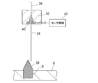
また、図3に示されているように、ニードル28は導電性材料からなる固定部材40によってニードル保持部30に固定されている。ニードル28の基端には、液の吸入と吐出を行なうポンプ(図示は省略)に通じるチューブ36が接続されている。固定部材40にはセンサ回路42が接続されている。
ニードル28は金属製であり導電性を有する。ニードル28が他の導電性物体に接近したときのニードルと導電性物体の間の静電容量の変化を検知する静電容量センサであり、ニードル28がその導電性物体に接触し又は一定の距離まで接近したことを検知するタッチセンサをなしている。センサ回路42はニードル28を通してその静電容量を検出し、静電容量の大きさによってニードル28の先端が導電性物体に接触又は一定の距離まで接近したことを検知する。このタッチセンサはティーチングの際のニードル28の位置決めに用いられる。
38はサンプルラック6の所定の試料設置部8に設置されたティーチング用のジグである。このジグ38の上部は上面中央部を頂点とする円錐形状となっており、弾力性とともに導電性を有する材料により構成されている。ジグ38の頂点は尖端形状であってもよいし、丸みを帯びた形状であってもよい。ジグ38を構成する材料としては、例えば導電性ゴム、導電性プラスチックなどが挙げられる。ジグ38が導電性材料で構成されていることにより、ティーチングの際に、タッチセンサ(センサ回路)42によってニードル28がジグ38に接触し又は一定の距離まで接近したことを検知することができる。ティーチングについては後述する。
ニードルアセンブリ10の移動範囲内でサンプルラック6の側方に、6方バルブ22が設けられている。6方バルブ22は6つのポートを備え、それらのポート間の接続を選択的に切り換えることができる。6方バルブ22のポートのうちの1ポートは試料注入口であるインジェクションポート24となっている。ニードルアセンブリ10のニードル28が採取した試料はこのインジェクションポート24を通じて液体クロマトグラフに注入されるようになっている。6方バルブ22の他の1ポートに移動相供給用の流路が接続され、さらに他の1ポートには分析カラムが接続されている。さらに、6方バルブ22の他の2ポート間はサンプルループによって接続されており、インジェクションポート24を通じて注入された試料がサンプルループに捕捉されるようになっている。残りの1ポートは不要な液を排出するためのドレインポートである。
ニードル28で採取した試料を液体クロマトグラフに注入する際は、6方バルブ22を、インジェクションポート24がサンプルループを介してドレインに接続されるようにした状態にし、インジェクションポートから試料を注入する。注入された試料はサンプルループに捕捉される。その後、サンプルループが移動相送液用の流路と分析カラムの間に接続された状態になるように6方バルブ22を切り換え、サンプルループに捕捉された試料を移動相によって分析カラムへ導く。
ニードルアセンブリ10の移動範囲内で6方バルブ22の近傍には洗浄ポート26が設けられている。洗浄ポート26はインジェクションポート24への試料注入を行なったニードル28の洗浄を行なうためのポートであり、洗浄液が貯留されている。洗浄ポート26にニードル28を挿入し、洗浄液の吸入と吐出を繰り返し行なうことで、ニードル28内部の洗浄を行なうことができる。
次に、この自動試料注入装置の制御系統の一例について図4を用いて説明する。
この自動試料注入装置の動作管理を行なう演算制御装置44が設けられており、演算制御装置44はニードル28の駆動制御を行なうニードル駆動制御部64に接続されている。演算制御装置44は汎用のパーソナルコンピュータ又は専用のコンピュータによって実現することができる。
演算制御装置44はニードル28の駆動を制御するための駆動手段46を備えている。駆動手段46は指定された分析項目などの動作項目に応じてニードル28を駆動すべき命令信号をニードル駆動制御部64に送るように構成されている。駆動手段46から命令信号を受けたニードル駆動制御部64は、その命令に応じたパルス数をニードル駆動機構66を構成するX方向駆動用、Y方向駆動用、Z方向駆動用の各パルスモータに与え、ニードル28を駆動するようになっている。ニードル駆動機構66には、ニードル28を介して液の吸入と吐出を行なうポンプを駆動するモータも含まれており、駆動手段46はニードル駆動制御部64を介してこのポンプの動作制御も行なうようになっている。
演算制御装置44は、さらに、サンプリング動作実行手段48、ティーチング動作実行手段50、ニードル下降位置記憶部52、ティーチング動作実行位置設定手段54、デフォルト位置記憶部56、ジグ形状記憶部57、ニードル位置割出手段58、ティーチング情報記憶部60及び頂点位置割出手段62を備えている。
サンプリング動作実行手段48は、ニードル28を目的の試料容器上の位置へ移動させてから下降させ、ニードル28の先端を試料容器内に挿入して試料を吸入し、その後、ニードル28をインジェクションポート24の位置へ移動させて試料を注入するというサンプリング動作を、駆動手段46を介して実行するように構成されたものである。サンプリング動作の際、目的の試料容器の位置へニードル28を位置決めするために、ニードル下降位置記憶部52に記憶されている情報が参照される。ニードル下降位置記憶部52には、ティーチングにより割り出されたニードル28の下降位置情報が記憶されている。
ティーチングは、サンプリング動作の際にニードル28を目的の試料容器の正しい位置に配置するためのニードル28の駆動量を設定するための準備処理であるが、この自動試料注入装置は、操作者がティーチングを実行すべき入力を行なうだけで自動的にティーチングが実行され、それによって得られたニードル下降位置の情報がニードル下降位置記憶部52に記憶されるように構成されている。
ティーチング動作実行手段50は、操作者によってティーチングを実行すべき入力がなされたときに、駆動手段46を介してティーチング動作を実行するように構成されている。ティーチング動作とは、サンプルラック6の所定の試料設置部8に設置されたジグ38(図3参照)の上方からニードル28を下降させていき、センサ回路42が、ニードル28の先端がジグ38に接触又は略接触したことを検知したときのニードル28先端のX方向、Y方向及びZ方向における位置情報(ティーチング情報という)を取得する動作である。サンプルラック6の複数の試料設置部8のうち、ティーチングの際にジグ38が設置される試料設置部8をティーチング位置という。ティーチング動作実行手段50は、このティーチング位置上の複数の位置(ティーチング動作実行位置という)においてティーチング動作を実行するように構成されている。各ティーチング動作実行位置について得られたティーチング情報はティーチング情報記憶部60に記憶される。
頂点位置割出手段62は、複数回のティーチング動作によってティーチング情報記憶部60に蓄積されたティーチング情報に基づいて、ジグ38の頂点位置を割り出すように構成されている。ジグ38の頂点位置はその試料設置部8に設置される試料容器の中心位置に相当するため、ジグ38の頂点位置を割り出すことでサンプルラック6の各試料設置部8における試料容器の中心位置を割り出すことができる。ジグ38の形状(寸法)はジグ形状記憶部57に記憶されており、ジグ38の頂点位置(X方向、Y方向及びZ方向)が割り出されれば、そこから試料容器の底部の正確な位置を割り出すことができる。割り出された試料容器の底部の位置の情報がニードル下降位置記憶部52に記憶される。このニードル下降位置記憶部52に記憶された試料容器の底部の位置情報をサンプリング動作実行手段48が参照してサンプリング動作を実行することで、ニードル28の先端を試料容器の底部の位置に正確に位置決めして試料の吸入を行なうことができる。
ティーチング位置は予め設定されているため、自動試料注入装置のファームウェアがサンプルラック6に設置されたジグ38のおおよその位置を把握している。ティーチング動作実行位置はティーチング動作実行位置設定手段54が設定するように構成されている。ティーチングの際、ティーチング位置上においてニードル28を最初に配置すべきデフォルト位置が予め設定されており、デフォルト位置記憶部56に記憶されている。ティーチングの際、ニードル28は必ず最初にそのデフォルト位置に配置されるようになっている。ティーチング動作実行位置設定手段54は、そのデフォルト位置から水平面内方向であるX方向又はY方向へ一定の距離(一定パルス数)ずらした位置をティーチング動作実行位置として設定する。
ティーチング動作実行位置設定手段54は、ティーチング開始時にすべてのティーチング動作実行位置を設定するようになっていてもよい。また、ジグ形状記憶部57にはジグ38の形状(寸法)に関する情報が記憶されているため、ティーチング動作が2回以上実行されれば、ニードル28を頂点位置に近づけるために移動させるべき方向を予測することができる。したがって、ティーチング動作実行位置設定手段54は、少なくとも2回のティーチング動作が実行された後は、それらのティーチング動作で得られたティーチング情報とジグ形状記憶部57の情報に基づき、ティーチング動作実行位置がジグ38の頂点に近づくように次のティーチング動作実行位置を設定するようになっていてもよい。そうすれば、より正確にジグ38の頂点位置の割出しを行なうことができる。
ティーチング動作の際にセンサ回路42が、ニードル28の先端がジグ38に接触又は略接触したことを検知したときのニードル28先端の位置は、ニードル位置割出手段58によって割り出されるようになっている。ニードル位置割出手段58は、ニードル駆動制御部64がニードル駆動機構66の各パルスモータへ与えるパルス電圧のカウント数を取り込むことによって割り出すように構成されており、ニードル位置割出手段58によって割り出されたニードル28の位置情報がティーチング情報としてティーチング情報記憶部60に記憶される。
次に、ティーチングの際の装置の動作の一例を図4とともに図5のフローチャートを用いて説明する。
所定の試料設置部8(ティーチング位置)にジグ38が設置されたサンプルラック6が装置に収容された状態で、ティーチングを実行する旨の入力が操作者によってなされると、ジグ38の配置されている試料設置部8上のデフォルト位置にニードル28を移動させ、そのデフォルト位置においてティーチング動作を実行する。ティーチング動作は、ニードル28がジグ38に接触又は略接触するまでニードル28を下降させ、ニードル28をジグ38に接触又は略接触したところで停止させ、そのときのニードル28のX方向、Y方向及びZ方向の位置座標(X,Y,Z)を割り出す動作である。割り出したニードル28の位置情報はティーチング情報記憶部60にティーチング情報として記憶される。
ニードル28を上昇させ、ニードル28の水平面内の位置をX方向又はY方向に一定のパルス分だけずらして次のティーチング動作実行位置に配置した後、上記のティーチング動作を実行する。このティーチング動作を予め設定された所定の箇所数(例えば、16箇所)のティーチング動作実行位置において実行する。すべてのティーチング動作実行位置について得られたティーチング情報に基づいてジグ38の頂点位置を割り出し、その頂点位置の情報に基づいてニードル下降位置を求め、ニードル下降位置記憶部52に記憶させる。サンプルラック6の複数の試料設置部8がティーチング位置として設定されている場合には、すべてのティーチング位置について上記の動作を実行する。
ティーチング動作により得られたティーチング情報の一例を表1に示す。

表1は、16箇所のティーチング動作実行位置(X1,Y1)、(X1,Y2)、(X1,Y3)、(X1,Y4)、(X2,Y1)、(X2,Y2)、(X2,Y3)、(X2,Y4)、(X3,Y1)、(X3,Y2)、(X3,Y3)、(X3,Y4)、(X4,Y1)、(X4,Y2)、(X4,Y3)、(X4,Y4)においてティーチング動作を実行したときに得られたニードル28のZ方向(上向きを正とする)の位置情報(単位はmm)である。表1から、ティーチング動作実行位置が(X3,Y3)のときにニードル28のZ方向の位置が最大(52.3mm)となっており、この位置がジグ38の頂点位置であると推測することができる。
なお、ティーチングの精度をさらに高めるために、上記ティーチングによりジグ38の頂点位置と推測された位置のX座標及びY座標をデフォルト位置として、その位置の周囲の複数箇所をティーチング動作実行位置として再度設定し、ティーチング動作を実行するようにしてもよい。
2 筐体
4 扉
6 サンプルラック
8 試料設置部
10 ニードルアセンブリ
12 支持台
14,20 ガイドレール
16 パルスモータ
18 ベルト
22 6方バルブ
24 インジェクションポート
26 洗浄ポート
28 ニードル
30 ニードル保持部
32 棒ネジ
34 筐体(ニードルアセンブリ)
36 チューブ
38 ジグ
40 固定部材
42 センサ回路(静電容量センサ)
44 演算制御装置
46 駆動手段
48 サンプリング動作実行手段
50 ティーチング動作実行手段
52 ニードル下降位置記憶部
54 ティーチング動作実行位置設定手段
56 デフォルト位置記憶部
57 ジグ形状記憶部
58 ニードル位置割出手段
60 ティーチング情報記憶部
62 頂点位置割出手段
64 ニードル駆動制御部
66 ニードル駆動機構
4 扉
6 サンプルラック
8 試料設置部
10 ニードルアセンブリ
12 支持台
14,20 ガイドレール
16 パルスモータ
18 ベルト
22 6方バルブ
24 インジェクションポート
26 洗浄ポート
28 ニードル
30 ニードル保持部
32 棒ネジ
34 筐体(ニードルアセンブリ)
36 チューブ
38 ジグ
40 固定部材
42 センサ回路(静電容量センサ)
44 演算制御装置
46 駆動手段
48 サンプリング動作実行手段
50 ティーチング動作実行手段
52 ニードル下降位置記憶部
54 ティーチング動作実行位置設定手段
56 デフォルト位置記憶部
57 ジグ形状記憶部
58 ニードル位置割出手段
60 ティーチング情報記憶部
62 頂点位置割出手段
64 ニードル駆動制御部
66 ニードル駆動機構
Claims (5)
- 試料を収容した試料容器を設置する試料設置部を備えたサンプルラックと、
前記試料設置部に設置された試料容器から試料を採取するニードルと、
前記ニードルが採取した試料を注入する試料注入口と、
前記ニードルを水平面内方向と鉛直方向に移動させるニードル駆動機構と、
前記サンプリング時にニードルが下降すべき位置を設定するティーチングの際に、ティーチング位置として設定された所定の前記試料設置部に設置されて使用されるジグであって、サンプリング時に前記ニードルを下降させるべき位置に相当する位置を頂点とする立体形状を有するジグと、
前記ニードル先端が前記ジグに接触又は略接触したことを検知するタッチセンサと、
前記ニードルを通して試料の吸引と吐出を行なうポンプと、
前記ニードル駆動機構による前記ニードルの駆動量に基づいて前記ニードル先端の位置を割り出すように構成されたニードル位置割出手段と、
ティーチングを実行すべき入力がなされたときに、前記ティーチング位置として設定されている前記試料設置部上の複数の位置をティーチング動作実行位置とし、前記タッチセンサが前記ニードル先端による前記ジグへの接触又は略接触を検知するまで前記ニードルを下降させ、前記ニードルが前記ジグに接触又は略接触したときの前記ニードルの水平面内方向及び前記鉛直方向の位置を前記ニードル位置割出手段によって割り出すティーチング動作を、それぞれの前記ティーチング動作実行位置について実行するように構成されたティーチング動作実行手段と、
前記各ティーチング動作実行位置での前記ティーチング動作により割り出された前記ニードルの位置の情報をティーチング情報として記憶するティーチング情報記憶部と、
前記ティーチング情報記憶部に記憶された前記ティーチング情報に基づいて前記ジグの前記頂点の位置を割り出して前記ニードルの下降位置を決定するように構成された頂点位置割出手段と、を備えた自動試料注入装置。 - 前記ニードル及びジグは導電性材料で構成されており、
前記タッチセンサは静電容量センサである請求項1に記載の自動試料注入装置。 - 前記ジグは弾力性を有する材料で構成されている請求項1又は2に記載の自動試料注入装置。
- サンプリング時に試料採取用のニードルを下降させるべき位置を決定するために、以下のステップを備えたティーチング方法。
ティーチングを行なうべき位置に、サンプリング時に前記ニードルを下降させるべき位置に相当する位置を頂点とする立体形状を有するジグを配置するジグ配置ステップ、
前記ティーチングを行なうべき位置に配置された前記ジグの上方の水平面内の複数の位置から前記ニードルの先端が前記ジグに接触するまで鉛直下方向に前記ニードルを下降させる動作を繰り返し行なう下降動作ステップ、
前記下降動作ステップにおける各下降動作の際に、前記ニードルの先端が前記ジグに接触したときの前記ニードルの水平面内方向及び鉛直方向の位置を割り出すニードル位置割出ステップ、及び、
前記ニードル位置割出ステップにおいて割り出された前記各下降動作の際のニードル位置に基づいて前記ジグの前記頂点の位置を割り出し、割り出した前記ジグの前記頂点の位置に基づいてサンプリングの際の前記ニードルの下降位置を決定するニードル下降位置決定ステップ。 - 前記ジグは導電性材料で構成し、前記ニードルに静電容量センサを設けることによって、前記ニードル先端が前記ジグに接触したことを検知する請求項4に記載のティーチング方法。
Priority Applications (1)
| Application Number | Priority Date | Filing Date | Title |
|---|---|---|---|
| JP2015550625A JPWO2015079873A1 (ja) | 2013-11-27 | 2014-11-05 | 自動試料注入装置 |
Applications Claiming Priority (2)
| Application Number | Priority Date | Filing Date | Title |
|---|---|---|---|
| JP2013-244590 | 2013-11-27 | ||
| JP2013244590 | 2013-11-27 |
Publications (1)
| Publication Number | Publication Date |
|---|---|
| WO2015079873A1 true WO2015079873A1 (ja) | 2015-06-04 |
Family
ID=53198821
Family Applications (1)
| Application Number | Title | Priority Date | Filing Date |
|---|---|---|---|
| PCT/JP2014/079285 Ceased WO2015079873A1 (ja) | 2013-11-27 | 2014-11-05 | 自動試料注入装置 |
Country Status (2)
| Country | Link |
|---|---|
| JP (1) | JPWO2015079873A1 (ja) |
| WO (1) | WO2015079873A1 (ja) |
Cited By (9)
| Publication number | Priority date | Publication date | Assignee | Title |
|---|---|---|---|---|
| JP2016125908A (ja) * | 2015-01-05 | 2016-07-11 | 株式会社島津製作所 | 自動試料採取装置 |
| CN113341001A (zh) * | 2020-03-02 | 2021-09-03 | 安捷伦科技有限公司 | 在样品容器转移期间利用信息检测进行样品处理 |
| WO2021188530A1 (en) * | 2020-03-17 | 2021-09-23 | Waters Technologies Corporation | Needle drive, system and method |
| WO2021188519A1 (en) * | 2020-03-17 | 2021-09-23 | Waters Technologies Corporation | Sample manager, system and method |
| CN114174822A (zh) * | 2019-07-29 | 2022-03-11 | 沃特世科技公司 | 用于液相色谱的用于机器人装载和卸载样品管理器的接口模块 |
| CN115494187A (zh) * | 2021-06-17 | 2022-12-20 | 株式会社岛津制作所 | 液相色谱仪用的自动采样器 |
| WO2023120088A1 (ja) * | 2021-12-24 | 2023-06-29 | 株式会社日立ハイテク | 自動分析装置およびその制御方法 |
| JP2024508713A (ja) * | 2021-02-11 | 2024-02-28 | シーメンス・ヘルスケア・ダイアグノスティックス・インコーポレイテッド | 診断検査室システムの構成要素を位置合わせする装置および方法 |
| US11940456B2 (en) | 2018-09-11 | 2024-03-26 | Becton Dickinson And Company | Robotic sample preparation system for diagnostic testing with automated position learning |
Citations (4)
| Publication number | Priority date | Publication date | Assignee | Title |
|---|---|---|---|---|
| JPS63243881A (ja) * | 1987-03-31 | 1988-10-11 | Shimadzu Corp | 自動試料注入装置 |
| JP2005300330A (ja) * | 2004-04-12 | 2005-10-27 | Nikon Corp | 位置測定方法 |
| JP2008281365A (ja) * | 2007-05-08 | 2008-11-20 | Shimadzu Corp | マイクロチップ電気泳動装置 |
| JP2011022086A (ja) * | 2009-07-17 | 2011-02-03 | Shimadzu Corp | 液体クロマトグラフの自動試料注入装置 |
-
2014
- 2014-11-05 JP JP2015550625A patent/JPWO2015079873A1/ja active Pending
- 2014-11-05 WO PCT/JP2014/079285 patent/WO2015079873A1/ja not_active Ceased
Patent Citations (4)
| Publication number | Priority date | Publication date | Assignee | Title |
|---|---|---|---|---|
| JPS63243881A (ja) * | 1987-03-31 | 1988-10-11 | Shimadzu Corp | 自動試料注入装置 |
| JP2005300330A (ja) * | 2004-04-12 | 2005-10-27 | Nikon Corp | 位置測定方法 |
| JP2008281365A (ja) * | 2007-05-08 | 2008-11-20 | Shimadzu Corp | マイクロチップ電気泳動装置 |
| JP2011022086A (ja) * | 2009-07-17 | 2011-02-03 | Shimadzu Corp | 液体クロマトグラフの自動試料注入装置 |
Cited By (15)
| Publication number | Priority date | Publication date | Assignee | Title |
|---|---|---|---|---|
| JP2016125908A (ja) * | 2015-01-05 | 2016-07-11 | 株式会社島津製作所 | 自動試料採取装置 |
| US12474358B2 (en) | 2018-09-11 | 2025-11-18 | Becton , Dickinson And Company | Robotic sample preparation system for diagnostic testing with automated position learning |
| US11940456B2 (en) | 2018-09-11 | 2024-03-26 | Becton Dickinson And Company | Robotic sample preparation system for diagnostic testing with automated position learning |
| CN114174822A (zh) * | 2019-07-29 | 2022-03-11 | 沃特世科技公司 | 用于液相色谱的用于机器人装载和卸载样品管理器的接口模块 |
| CN113341001A (zh) * | 2020-03-02 | 2021-09-03 | 安捷伦科技有限公司 | 在样品容器转移期间利用信息检测进行样品处理 |
| CN115667908A (zh) * | 2020-03-17 | 2023-01-31 | 沃特世科技公司 | 样品管理器、系统和方法 |
| US11879875B2 (en) | 2020-03-17 | 2024-01-23 | Waters Technologies Corporation | Sample manager, system and method |
| US11913916B2 (en) | 2020-03-17 | 2024-02-27 | Waters Technologies Corporation | Needle drive, system and method |
| WO2021188519A1 (en) * | 2020-03-17 | 2021-09-23 | Waters Technologies Corporation | Sample manager, system and method |
| WO2021188530A1 (en) * | 2020-03-17 | 2021-09-23 | Waters Technologies Corporation | Needle drive, system and method |
| EP4585920A3 (en) * | 2020-03-17 | 2025-11-26 | Waters Technologies Corporation | Needle drive |
| JP2024508713A (ja) * | 2021-02-11 | 2024-02-28 | シーメンス・ヘルスケア・ダイアグノスティックス・インコーポレイテッド | 診断検査室システムの構成要素を位置合わせする装置および方法 |
| JP7730913B2 (ja) | 2021-02-11 | 2025-08-28 | シーメンス・ヘルスケア・ダイアグノスティックス・インコーポレイテッド | 診断検査室システムの構成要素を位置合わせする装置および方法 |
| CN115494187A (zh) * | 2021-06-17 | 2022-12-20 | 株式会社岛津制作所 | 液相色谱仪用的自动采样器 |
| WO2023120088A1 (ja) * | 2021-12-24 | 2023-06-29 | 株式会社日立ハイテク | 自動分析装置およびその制御方法 |
Also Published As
| Publication number | Publication date |
|---|---|
| JPWO2015079873A1 (ja) | 2017-03-16 |
Similar Documents
| Publication | Publication Date | Title |
|---|---|---|
| WO2015079873A1 (ja) | 自動試料注入装置 | |
| WO2014162921A1 (ja) | オートサンプラ | |
| US9671419B2 (en) | Liquid collection device and automated analyzer provided therewith | |
| CN204422556U (zh) | 加样设备及具有该加样设备的血凝仪 | |
| CN108982886B (zh) | 样本分析仪进样结构、样本分析仪及采样方法 | |
| JP6274081B2 (ja) | 液採取装置及びその液採取装置を備えた自動分析装置 | |
| US20200377833A1 (en) | Cell picking device | |
| CN109073608B (zh) | 自动进样器 | |
| JP5158032B2 (ja) | 液体クロマトグラフの自動試料注入装置 | |
| CN203385745U (zh) | 一种用于全自动检测分析仪的取样机械臂 | |
| CN107102159B (zh) | 用于多样品水质量同时在线检测的自动化仪器及其检测方法 | |
| CN105874337B (zh) | 确定至少一个制图学标志物的位置的方法 | |
| CN205861711U (zh) | 一种血型分析仪的加样针机构 | |
| JP5163903B2 (ja) | 分注方法 | |
| JP2012163334A (ja) | オートサンプラ | |
| JP6388082B2 (ja) | オートサンプラ | |
| JP5733462B2 (ja) | 自動試料注入装置 | |
| CN203881788U (zh) | 化学发光免疫分析仪试管架 | |
| CN114868022A (zh) | 自动分析装置 | |
| CN104482856A (zh) | 一种医用诊断仪器上耗材的定位方法和系统 | |
| JP4085954B2 (ja) | 液体クロマトグラフ用のオートサンプラ | |
| JP2009058299A (ja) | 分注装置のティーチング方法 | |
| JP2016061617A (ja) | ティーチング補助装置及びそのティーチング補助装置を用いたティーチング方法 | |
| KR20090048330A (ko) | 도포장치 및 도포방법 | |
| CN207502227U (zh) | 一种具有清洁功能的液体样品取样装置 |
Legal Events
| Date | Code | Title | Description |
|---|---|---|---|
| 121 | Ep: the epo has been informed by wipo that ep was designated in this application |
Ref document number: 14866120 Country of ref document: EP Kind code of ref document: A1 |
|
| ENP | Entry into the national phase |
Ref document number: 2015550625 Country of ref document: JP Kind code of ref document: A |
|
| NENP | Non-entry into the national phase |
Ref country code: DE |
|
| 122 | Ep: pct application non-entry in european phase |
Ref document number: 14866120 Country of ref document: EP Kind code of ref document: A1 |