WO2015079846A1 - 底付き円筒容器の成形方法 - Google Patents
底付き円筒容器の成形方法 Download PDFInfo
- Publication number
- WO2015079846A1 WO2015079846A1 PCT/JP2014/078507 JP2014078507W WO2015079846A1 WO 2015079846 A1 WO2015079846 A1 WO 2015079846A1 JP 2014078507 W JP2014078507 W JP 2014078507W WO 2015079846 A1 WO2015079846 A1 WO 2015079846A1
- Authority
- WO
- WIPO (PCT)
- Prior art keywords
- container
- punch
- die
- side wall
- shoulder
- Prior art date
- Legal status (The legal status is an assumption and is not a legal conclusion. Google has not performed a legal analysis and makes no representation as to the accuracy of the status listed.)
- Ceased
Links
Images






Classifications
-
- B—PERFORMING OPERATIONS; TRANSPORTING
- B21—MECHANICAL METAL-WORKING WITHOUT ESSENTIALLY REMOVING MATERIAL; PUNCHING METAL
- B21K—MAKING FORGED OR PRESSED METAL PRODUCTS, e.g. HORSE-SHOES, RIVETS, BOLTS OR WHEELS
- B21K23/00—Making other articles
-
- B—PERFORMING OPERATIONS; TRANSPORTING
- B21—MECHANICAL METAL-WORKING WITHOUT ESSENTIALLY REMOVING MATERIAL; PUNCHING METAL
- B21D—WORKING OR PROCESSING OF SHEET METAL OR METAL TUBES, RODS OR PROFILES WITHOUT ESSENTIALLY REMOVING MATERIAL; PUNCHING METAL
- B21D51/00—Making hollow objects
- B21D51/02—Making hollow objects characterised by the structure of the objects
- B21D51/10—Making hollow objects characterised by the structure of the objects conically or cylindrically shaped objects
-
- B—PERFORMING OPERATIONS; TRANSPORTING
- B21—MECHANICAL METAL-WORKING WITHOUT ESSENTIALLY REMOVING MATERIAL; PUNCHING METAL
- B21J—FORGING; HAMMERING; PRESSING METAL; RIVETING; FORGE FURNACES
- B21J5/00—Methods for forging, hammering, or pressing; Special equipment or accessories therefor
- B21J5/02—Die forging; Trimming by making use of special dies ; Punching during forging
-
- B—PERFORMING OPERATIONS; TRANSPORTING
- B21—MECHANICAL METAL-WORKING WITHOUT ESSENTIALLY REMOVING MATERIAL; PUNCHING METAL
- B21J—FORGING; HAMMERING; PRESSING METAL; RIVETING; FORGE FURNACES
- B21J5/00—Methods for forging, hammering, or pressing; Special equipment or accessories therefor
- B21J5/06—Methods for forging, hammering, or pressing; Special equipment or accessories therefor for performing particular operations
- B21J5/08—Upsetting
-
- B—PERFORMING OPERATIONS; TRANSPORTING
- B21—MECHANICAL METAL-WORKING WITHOUT ESSENTIALLY REMOVING MATERIAL; PUNCHING METAL
- B21J—FORGING; HAMMERING; PRESSING METAL; RIVETING; FORGE FURNACES
- B21J5/00—Methods for forging, hammering, or pressing; Special equipment or accessories therefor
- B21J5/06—Methods for forging, hammering, or pressing; Special equipment or accessories therefor for performing particular operations
- B21J5/12—Forming profiles on internal or external surfaces
-
- B—PERFORMING OPERATIONS; TRANSPORTING
- B21—MECHANICAL METAL-WORKING WITHOUT ESSENTIALLY REMOVING MATERIAL; PUNCHING METAL
- B21D—WORKING OR PROCESSING OF SHEET METAL OR METAL TUBES, RODS OR PROFILES WITHOUT ESSENTIALLY REMOVING MATERIAL; PUNCHING METAL
- B21D53/00—Making other particular articles
- B21D53/26—Making other particular articles wheels or the like
- B21D53/34—Making other particular articles wheels or the like brake drums
Definitions
- the present invention relates to a molding method for increasing the thickness of a container shoulder of a cylindrical container with a bottom, forming the container at a right angle, and forming a container side wall in a straight line.
- the shoulder connecting the bottom and the side wall perpendicular to the bottom is formed into a right angle and transmitted. It is required to have a sufficient thickness to withstand torque. Further, the side wall portion is also required to have a sufficient thickness.
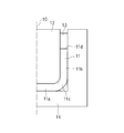
- FIG. 1 is a view showing a state of a mold and a cylindrical container 11 with a bottom before molding in a conventional molding method.
- the conventional molding method first, the container bottom 11 a of the bottomed cylindrical container 11 is held between the inner punch 12 and the die 14. Subsequently, the container side wall 11b in the space surrounded by the inner punch 12, the outer punch 13, and the die 14 is pushed into the die bottom 14a side by the outer punch 13 as shown in FIG. The part 11c is increased in thickness and formed into a right angle, and the container side wall part 11b is formed in a straight line.
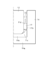
- the outer punch 13 is deformed in the plate thickness direction as indicated by the dotted line in FIG.
- Patent Document 1 discloses a molding method that suppresses the occurrence of folding wrinkles. This molding method forms the container shoulder portion into an obtuse angle, and shapes the container shoulder portion at a right angle. It is not a thing. Moreover, in this shaping
- Patent Document 2 discloses a molding method in which a container shoulder is thickened at a right angle using a pressure roller, but this molding method requires a special device such as a pressure roller.
- Patent Document 3 in order to prevent defects due to buckling, the vertical wall of an intermediate product that has been previously formed into a cup shape is ironed with a die and a punch to form a wall in the vertical wall near the inner periphery of the corner.
- a molding method is disclosed in which the outer periphery of the corner is squared by pressing the meat reservoir with a punch and moving the meat in the reservoir to the corner of the outer periphery of the corner.
- this molding method requires a special process of ironing to form a meat pool before the squaring.
- the outer shape of the presser punch and the presser punch is provided in order to provide a molding method that does not have wrinkles when the bottom part and the wall part are formed at right angles by increasing the corners of the cylindrical cup.
- the deep-drawn cup is placed on the press punch using a die having an upset punch and a die that are arranged in the axial direction and movable relative to the press punch in the axial direction.
- the present invention has been made in view of the above circumstances, and increases the container shoulder of the bottomed cylindrical container while suppressing the occurrence of folding wrinkles without requiring special equipment or special processing in the previous stage.
- An object is to form the container side wall at right angles and form the container side wall in a straight line.
- a method of forming a bottomed cylindrical container using a bottomed cylindrical container having a container bottom, a container side wall, and a curved container shoulder connecting the container bottom and the container side wall as a workpiece, Mutually central axes are arranged coaxially, With an inner punch, An annular first outer punch disposed along the outer periphery of the inner punch and having an R-shaped punch shoulder at an outer edge in a direction perpendicular to the central axis of the press surface portion; An annular second outer punch that is disposed along an outer periphery of the first outer punch and that pushes in a container opening end of the bottomed cylindrical container; A die bottom and a die side wall connected perpendicularly to an outer edge of the die bottom, and a die disposed opposite to the inner punch, the first outer punch and the second outer punch, and In a state where the container bottom is sandwiched between the inner punch and the die
- a method for forming a cylindrical container with a bottom comprising a step of linearly forming in a direction along an axis. [2] In the first outer punch and the second outer punch, a step groove portion is formed on the press surface portion through the R-shaped punch shoulder portion, and the bottom portion of the step groove portion forms the bottom.
- the container shoulder of the bottomed cylindrical container is increased in thickness and formed into a right angle, And a container side wall part can be shape
- FIG. 1 is a cross-sectional view showing a mold before molding and a cylindrical container with a bottom in a conventional molding method.
- FIG. 2 is a cross-sectional view showing a mold and a cylindrical container with a bottom after molding by a conventional molding method.
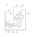
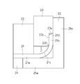
- FIG. 3 is a cross-sectional view showing a mold and a cylindrical container with a bottom before molding in the first step according to the embodiment.
- FIG. 4 is a cross-sectional view showing a mold and a cylindrical container with a bottom during molding in the first step according to the embodiment.
- FIG. 5 is a cross-sectional view showing a mold and a cylindrical container with a bottom during molding in the first step according to the embodiment.
- FIG. 6 is a cross-sectional view showing a mold and a cylindrical container with a bottom during molding in the first step according to the embodiment.
- FIG. 7 is a cross-sectional view showing a mold and a cylindrical container with a bottom during molding in the first step according to the embodiment.
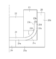
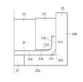
- FIG. 8 is a cross-sectional view showing the mold and the cylindrical container with the bottom after the first step according to the embodiment.
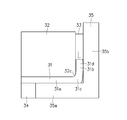
- FIG. 9 is a cross-sectional view showing a mold before molding and a cylindrical container with a bottom in the second step according to the embodiment.
- FIG. 10 is a cross-sectional view showing a mold and a cylindrical container with a bottom during molding in the second step according to the embodiment.
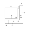
- FIG. 11 is a cross-sectional view showing the mold and the cylindrical container with the bottom after the second step according to the embodiment.
- FIG. 12 is a cross-sectional view showing a mold and a cylindrical container with a bottom before molding in a comparative example.
- FIG. 13A is a cross-sectional view showing a mold and a cylindrical container with a bottom during molding in a comparative example.
- FIG. 13B is an enlarged cross-sectional view showing a mold during molding and a cylindrical container with a bottom in a comparative example.
- FIG. 14A is a cross-sectional view showing a mold and a cylindrical container with a bottom during molding in a comparative example.
- FIG. 14B is an enlarged cross-sectional view showing a mold during molding and a cylindrical container with a bottom in a comparative example.
- FIG. 15A is a cross-sectional view showing a mold after molding and a cylindrical container with a bottom in a comparative example.
- FIG. 15B is an enlarged cross-sectional view showing a mold and a cylindrical container with a bottom after molding in a comparative example.
- FIG. 16: is sectional drawing which shows the metal mold
- the first press mold is used to increase the thickness of the container shoulder of the bottomed cylindrical container and to form the container at a right angle, and to linearly form the container side wall. It has the 1st process to shape
- FIG. 3 is a cross-sectional view illustrating a mold (first press mold) and a cylindrical container with a bottom before molding in the first step according to the embodiment.
- first press mold a mold
- second press die a cylindrical container with a bottom before molding in the first step according to the embodiment.
- shaft object since the side cross section of the 1st press die and the 2nd press die mentioned later is an axis
- the molding object (work material) of the press machine in the first step is a bottomed cylindrical container 21 having a container bottom 21a, a container side wall 21b, and a curved container shoulder 21c connecting the container bottom 21a and the container side wall 21b. It is.
- the bottomed cylindrical container 21 that is a workpiece is formed in advance by drawing.
- the first press die has an inner punch 22, an outer punch 23, a knockout 24, and a die 25 whose central axes 20 are arranged coaxially with each other.
- the die 25 is fixed, and the other elements 22 to 23 can be moved up and down by a lifting mechanism.
- a hydraulic pressure, a servo motor or the like can be used for the lifting mechanism.
- the inner punch 22 since the inner punch 22 only needs to be able to hold the container bottom 21a with the die 25, a spring or the like that applies an urging force in the direction of the die 25 can be used.
- the inner punch 22 has a cylindrical shape, and has a flat press surface portion 22a facing the knockout 24 and the die 25, and an outer peripheral surface portion 22b.
- the outer punch 23 is formed in an annular shape and is disposed along the outer peripheral surface portion 22 b of the inner punch 22.
- the outer punch 23 has a first press surface portion 23a that is annular in plan view and that faces the die 25, and an outer peripheral surface portion 23b.
- An annular step groove 23c is formed on the outer edge in the radial direction orthogonal to the central axis 20 of the first press surface portion 23a.
- the step groove portion 23c includes a circumferential side wall portion 23d and an annular bottom surface portion (referred to as a second press surface portion) 23e that is orthogonal to the side wall portion 23d.
- the side wall portion 23d and the first press surface portion 23a are connected by an R-shaped punch shoulder portion 23f.
- the outer diameter of the side wall 23d of the step groove 23c is substantially equal to the inner diameter of the container side wall 21b of the bottomed cylindrical container 21.
- the knockout 24 has a columnar shape and is used for removing the bottomed cylindrical container 21 formed by the first press mold from the first press mold, and is movable up and down by a mechanical drive source (not shown). It is a formula.
- the die 25 has a die bottom portion 25a and an annular die side wall portion 25b connected perpendicularly to the outer edge portion of the die bottom portion 25a.
- a hole 25c in which the knockout 24 is disposed is formed at the center of the die bottom 25a.
- the inner diameter of the die side wall 25b is substantially equal to the outer diameter of the container side wall 21b.
- the press machine lowers the inner punch 22 with respect to the bottomed cylindrical container 21 placed on the die 25 so that the container bottom 21a is held between the inner punch 22 and the die 25.
- the outer punch 23 is lowered while maintaining the state.
- the outer punch 23 is lowered, and the container opening end 21 d of the bottomed cylindrical container 21 enters the stepped groove 23 c of the outer punch 23.
- the container opening end 21d is separated from the second press surface portion 23e of the outer punch 23, and is restrained from the direction perpendicular to the central axis 20 by the step groove portion 23c and the die side wall portion 25b.
- the punch shoulder 23f comes into contact with the container shoulder 21c, and the container shoulder 21c and the container side wall 21b are deformed downward.
- the container bottom 21a has been described as being held in advance by the inner punch 22 and the die 25, the container bottom 21a only needs to be held when the punch shoulder 23f contacts the container shoulder 21c. That is, the timing may be such that the container bottom 21a is held between the inner punch 22 and the die 25 at the same time or immediately before the punch shoulder 23f contacts the container shoulder 21c.
- the second press surface portion 23e of the step groove portion 23c comes into contact with the container opening end 21d, and the container opening end 21d is pressed by the second press surface portion 23e.
- the container shoulder portion 21c and the container side wall portion 21b are deformed downward. That is, at the same time as or after the punch shoulder portion 23f comes into contact with the container shoulder portion 21c, the second press surface portion 23e of the step groove portion 23c comes into contact with and pushes into the container opening end 21d.
- the container side wall part 21b, the container shoulder part 21c, and the container bottom part 21a are formed while restraining deformation of the container side wall part 21b in the plate thickness direction and bringing the punch shoulder part 23f into close contact with the container shoulder part 21c. Therefore, it is possible to suppress the occurrence of folding wrinkles inside the container shoulder 21c.
- the outer punch 23 is further lowered from the state shown in FIG. At this time, in addition to pushing the container side wall portion 21b with the second press surface portion 23e of the outer punch 23, the portion on the container shoulder portion 21c side increased in the container bottom portion 21a is replaced with the first press surface portion 23a and the punch shoulder portion.
- the thickened portion of the container bottom 21a is caused to flow into the space of the die corner 25d, and the container shoulder 21c is thickened and formed into a right angle.
- the container shoulder 21c can be increased in thickness and formed into a right angle, and the container side wall 21b can be formed linearly in the direction along the central axis 20.
- the press raises the inner punch 22, the outer punch 23, and the knockout 24, and removes the bottomed cylindrical container 21 from the die 25.
- FIG. 9 is a cross-sectional view showing a mold (second press mold) and a cylindrical container with a bottom before molding in the second step according to the embodiment.
- the molding object (work material) of the press machine in the second step is a bottomed cylindrical container after molding in the first step, and hereinafter, the symbol of the bottomed cylindrical container after molding in the first step is 31,
- the parts of the bottomed cylindrical container 31 are referred to as a container bottom part 31a, a container side wall part 31b, a container shoulder part 31c, and a container opening end 31d.
- the second press die includes an inner punch 32 (inner punch for increasing the thickness), an outer punch 33 (outer punch for increasing the thickness), a knockout 34, and a die 35 (for increasing the thickness) whose central axes 30 are arranged coaxially. Die).
- the die 35 is fixed, and the other elements 32 to 33 can be moved up and down by a lifting mechanism.
- a hydraulic pressure, a servo motor or the like can be used for the lifting mechanism.
- a spring or the like that applies a biasing force in the direction of the die 35 can be used.
- the inner punch 32 has a cylindrical shape, and has a flat press surface portion 32a facing the knockout 34 and the die 35, an outer peripheral surface portion 32b, and an inner punch shoulder portion 32c that connects the flat surface portion 32a and the outer peripheral surface portion 32b.
- the outer diameter of the outer peripheral surface portion 32 b of the inner punch 32 is substantially equal to the inner diameter of the container side wall portion 31 b of the bottomed cylindrical container 31.
- the shape of the inner punch shoulder 32c is substantially the same as the shape of the punch shoulder 23f of the outer punch 23 used in the first step.
- the outer punch 33 is formed in an annular shape and is disposed along the outer peripheral surface portion 32 b of the inner punch 32.
- the outer punch 33 has a press surface portion 33 a that is annular in plan view and faces the die 35.
- the thickness of the outer punch 33 is larger than the plate thickness T of the container side wall 31b.
- the knockout 34 has a columnar shape for removing the bottomed cylindrical container 31 after being molded by the second press mold from the second press mold, and is movable up and down by a mechanical drive source (not shown). It is a formula.
- the die 35 has a die bottom part 35a and an annular die side wall part 35b connected perpendicularly to the outer edge part of the die bottom part 35a.
- a hole 35c in which the knockout 34 is disposed is formed at the center of the die bottom 35a.
- the inner diameter of the die side wall 35b is larger than the outer diameter of the container side wall 31b in order to increase the thickness of the container side wall 31b. That is, a gap is formed between the container side wall portion 31b and the die side wall portion 35b.
- the space S1 between the die side wall 35b and the inner punch 32 is larger than the plate thickness T of the container side wall 31b, and the outer punch 33 is disposed in the gap S1.
- the press machine lowers the inner punch 32 with respect to the bottomed cylindrical container 31 placed on the die 35 and holds the container bottom 31a between the inner punch 32 and the die 35.
- the outer punch 33 is lowered while maintaining the state.
- the outer punch 33 is lowered, and the container side wall portion 31b is installed in the space surrounded by the inner punch 32, the outer punch 33, and the die 35 to increase the thickness in the plate thickness direction. To do.
- the container shoulder portion 31c is formed in the middle of the second step. Does not leave the inner punch shoulder 32c. Therefore, it is possible to suppress the occurrence of folding wrinkles inside the container shoulder 31c.
- the container side wall 31b can be thickened in the plate thickness direction.
- the press raises the inner punch 32, the outer punch 33, and the knockout 34, and removes the bottomed cylindrical container 31 from the die 35.
- FIG. 12 a case will be described in which the second step is performed in a state where the container shoulder is not formed into a right angle.
- symbol of a cylindrical container with a bottom is set to 41, and each part of the cylindrical container 41 with a bottom is described as the container bottom part 41a, the container side wall part 41b, the container shoulder part 41c, and the container opening end 41d.
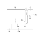
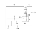
- a gap S2 is generated between the inner punch shoulder portion 32c and the container shoulder portion 41c as shown in FIGS. 13A and 13B during the second step. Then, as shown in FIGS.
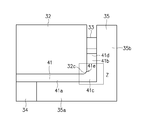
- the material of the bottomed cylindrical container 41 protrudes into the gap S2, and a fold 41e is generated inside the container shoulder 41c. Therefore, in the first step, it is necessary to carry out the thickening process until the container shoulder 41c is formed in a right angle.
- the bottomed cylindrical container 21 may be made of various known materials that can be plastically processed, such as steel, aluminum, a metal such as a trunk, or an alloy thereof. Moreover, although it demonstrated that the cylindrical container 21 with a bottom was shape
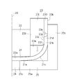
- the outer punch 23 is formed with the step groove portion 23c that is connected to the press surface portion 23a via the R-shaped punch shoulder portion 23f, and the bottom surface portion 23e of the step groove portion 23c.
- annular punch which pushes in the container opening end 21d of the cylindrical container 21 with a bottom was demonstrated, this invention is not limited to this. As shown in FIG.
- annular first outer punch 23I is disposed along the outer periphery of the inner punch 22 and has an R-shaped punch shoulder 23f on the outer edge in a direction perpendicular to the central axis 20 of the press surface portion 23a.
- annular second outer punch 23O that is arranged along the outer periphery of the first outer punch 23I and that pushes in the container opening end 21d of the bottomed cylindrical container 21.
- the outer punch 23 is lowered while the inner punch 22, the knockout 24, and the die 25 are fixed, so that the container shoulder portion 21c is formed into a right angle while increasing the thickness.
- the present invention is not limited to this. That is, in the first step, the outer punch 23 may be fixed and the inner punch 22, the knockout 24, and the die 25 may be raised to form the container shoulder portion 21c in a right angle while increasing the thickness.
- the inner punch 22, the knockout 24, and the die 25 may be raised while lowering the outer punch 23, thereby forming the container shoulder portion 21c in a right-angle shape while increasing the thickness.
- the outer side wall 33b is increased by lowering the outer punch 33 while the inner punch 32, the knockout 34, and the die 35 are fixed. It is not limited. That is, in the second step, the container side wall 21b may be increased by raising the inner punch 32, the knockout 34, and the die 35 with the outer punch 33 fixed. Further, the container side wall portion 21b may be increased by raising the inner punch 32, the knockout 34, and the die 35 while lowering the outer punch 33.
- each tool may be reversed.
- the knockouts 24 and 34 are provided.
- the knockouts 24 and 34 may be omitted.
- the hole 25a of the die 25 may be omitted, and the entire container bottom 21a may be supported by the die 25.
- the hole 35c of the die 35 may be omitted, and the entire container bottom 31a may be supported by the die 35.
- the bottomed cylindrical container after the first step or the second step may be removed from the dies 25 and 35 using, for example, a lifting machine.
- the present invention can be used to mold a cylindrical container with a bottom, which is a part that rotates and transmits torque, such as a drum or a hub used in an automatic transmission of an automobile.
Landscapes
- Engineering & Computer Science (AREA)
- Mechanical Engineering (AREA)
- Shaping Metal By Deep-Drawing, Or The Like (AREA)
- Forging (AREA)
Abstract
Description
しかしながら、従来方法では、外パンチ13で容器開口端11dをダイ底部14a側に押し込む途中で、図1に点線で示すように板厚方向に変形して、容器肩部11cの内側が内パンチ12のパンチ肩部から離れてしまうことがある。この場合、図2に示すように、容器肩部11cの内側に、表面が折れ込んで重なるようにして形成される皺状の疵(本願では折れ込み疵と呼ぶ)11dが発生するという問題がある。
特許文献2には、加圧ローラを用いて容器肩部を直角状に増肉する成形方法が開示されているが、この成形方法には、加圧ローラ等の特殊な装置が必要となる。
特許文献3には、座屈による欠陥を防止するために、あらかじめカップ状に成形された中間品の縦壁をダイとパンチでしごき加工し、隅部内周近傍の縦壁に肉溜まりを形成させ、該肉溜まりをパンチで押圧して該肉溜まりの肉を隅部外周の角部に移動させることによって隅部外周の角出しを行う成形方法が開示されている。しかしながら、この成形方法では、角出しの前段において、しごき加工して肉溜まりを形成するという特殊な加工が必要となる。
特許文献4には、円筒カップの角部を増肉させ、底面と壁部を直角に成形する際に表面が重なった疵のない成形法を提供するために、押えパンチと押えパンチの外周状に配置されるとともに、前記押えパンチに対して相対的に軸心方向に移動可能な据え込みパンチとダイスを備える金型を用いて、深絞り成形したカップを押えパンチの上に置き、押えパンチ及び据え込みパンチを押し上げて成形する際に、押えパンチ及び据え込みパンチをそれぞれの全ストロークの0.5倍以上0.7倍以下まで押し(第1の工程)、引き続き、押えパンチのみを押えパンチの全ストロークの0.8倍以上0.9倍以下まで押し(第2の工程)、引き続き、押えパンチ及び据え込みパンチをそれぞれの全ストロークまで押込み(第3の工程)、成形する成形方法が開示されている。しかしながら、この成形方法では、押えパンチ及び据え込みパンチを第1~第3の工程に移動させる必要があり、通常の複動プレス機では、3工程を要する。また、第1~第3の工程を1つのプレス機にて連続して行うには、高価な複動サーボプレス機が必要である。
[1] 容器底部、容器側壁部、及び前記容器底部と前記容器側壁部とを繋ぐ湾曲した容器肩部を有する底付き円筒容器を被加工材とする底付き円筒容器の成形方法であって、
互いに中心軸が同軸上に配置される、
内パンチと、
前記内パンチの外周に沿って配置され、プレス面部の前記中心軸に直交する方向の外縁部にR状のパンチ肩部を有する環状の第1の外パンチと、
前記第1の外パンチの外周に沿って配置され、前記底付き円筒容器の容器開口端を押し込む環状の第2の外パンチと、
ダイ底部及び前記ダイ底部の外縁部に垂直に接続するダイ側壁部を有し、前記内パンチ、前記第1の外パンチ及び前記第2の外パンチに対向配置されるダイと、を用いて、
前記内パンチと前記ダイとで前記容器底部を狭持した状態で、かつ前記第1の外パンチの側壁部と前記ダイの前記ダイ側壁部とで前記容器開口端を拘束した状態で、前記第1の外パンチ及び前記第2の外パンチを前記ダイの前記ダイ底部に向かって相対移動させることで、前記容器肩部を増肉するとともに直角状に成形し、かつ前記容器側壁部を前記中心軸に沿った方向に直線状に成形する工程を有することを特徴とする底付き円筒容器の成形方法。
[2] 前記第1の外パンチ及び前記第2の外パンチは、前記プレス面部に前記R状のパンチ肩部を介して連設する段差溝部が形成され、前記段差溝部の底面部で前記底付き円筒容器の容器開口端を押し込むようにした一の環状のパンチとして構成されることを特徴とする[1]に記載の底付き円筒容器の成形方法。
[3] 前記R状のパンチ肩部が前記容器肩部に接触するのと同時又はそれ以降に、前記第2の外パンチが前記容器開口端に当接する押し込むことを特徴とする[1]又は[2]に記載の底付き円筒容器の成形方法。
[4] 前記工程による成形後の前記底付き円筒容器の前記容器側壁部を板厚方向に増肉する後工程を有し、
前記後工程は、
互いに中心軸が同軸上に配置される、
増肉用内パンチと、
前記増肉用内パンチの外周に沿って配置される環状の増肉用外パンチと、
ダイ底部及び前記ダイ底部の外縁部に垂直に接続するダイ側壁部を有し、前記増肉用内パンチ及び前記増肉用外パンチに対向配置される増肉用ダイと、を用いて、
前記増肉用内パンチと前記増肉用ダイとで前記容器底部を狭持した状態で、前記増肉用内パンチと前記増肉用ダイの前記ダイ側壁部との隙間であって前記容器側壁部の板厚より大きい隙間に配置される前記増肉用外パンチを前記増肉用ダイの前記ダイ底部に向かって相対移動させることで、前記容器側壁部を据え込んで板厚方向に増肉することを特徴とする[1]に記載の底付き円筒容器の成形方法。
[5] 前記増肉用内パンチのパンチ肩部の形状が、前記第1工程における前記R状のパンチ肩部の形状と同等であることを特徴とする[4]に記載の底付き円筒容器の成形方法。
本実施形態に係る底付き円筒容器の成形方法では、第1プレス金型を用いて、底付き円筒容器の容器肩部を増肉するとともに直角状に成形し、かつ容器側壁部を直線状に成形する第1工程と、第1工程後に、第2のプレス金型を用いて、容器側壁部を板厚方向に増肉する第2工程とを有する。
図3は、実施形態に係る第1工程の成形前の金型(第1プレス金型)及び底付き円筒容器を示す断面図である。なお、第1プレス金型及び後述する第2プレス金型の側断面は軸対象であるため、中心軸から片側部分のみを示す。他の図面においても、同様である。
第1工程において、プレス機は、ダイ25上に載置された底付き円筒容器21に対して、内パンチ22を下降させて容器底部21aを内パンチ22とダイ25とにより狭持し、この状態を維持しながら外パンチ23を下降させる。
図4に示すように、外パンチ23をさらに下降させると、パンチ肩部23fが容器肩部21cに接触し、容器肩部21c及び容器側壁部21bを下方に変形させる。なお、容器底部21aを内パンチ22とダイ25とにより予め狭持しておくと説明したが、パンチ肩部23fが容器肩部21cに接触するときに容器底部21aが狭持されればよい。すなわち、パンチ肩部23fが容器肩部21cに接触するのと同時又はその直前に、容器底部21aを内パンチ22とダイ25とにより狭持するようなタイミングとしてもよい。
図9は、実施形態に係る第2工程の成形前の金型(第2プレス金型)及び底付き円筒容器を示す断面図である。
第2工程におけるプレス機の成形対象(被加工材)は、第1工程による成形後の底付き円筒容器であり、以下では、第1工程による成形後の底付き円筒容器の符号を31とし、底付き円筒容器31の各部を容器底部31a、容器側壁部31b、容器肩部31c、容器開口端31dと記す。
第2工程において、プレス機は、ダイ35上に載置された底付き円筒容器31に対して、内パンチ32を下降させて容器底部31aを内パンチ32とダイ35とにより狭持し、この状態を維持しながら外パンチ33を下降させる。
この場合、第2工程の途中で、図13A、図13Bに示すように、内パンチ肩部32cと容器肩部41cとの間に隙間S2が生じる。そして、この隙間S2に、図14A、図14B、図15A及び図15Bに示すように、底付き円筒容器41の素材が張り出し、容器肩部41cの内側に折れ込み疵41eが発生する。したがって、第1工程では、容器肩部41cが直角状に成形されるまで増肉処理を実施する必要がある。
また、底付き円筒容器21は絞り加工により事前に成形されると説明したが、例えば第1工程の前工程として、第1プレス金型の例えばダイ25を利用して、平板の素材から底付き円筒容器21を成形するようにしてもよい。
(変形例1)
上述の実施形態では、第1プレス金型において、外パンチ23が、プレス面部23aにR状のパンチ肩部23fを介して連設する段差溝部23cが形成され、段差溝部23cの底面部23eで底付き円筒容器21の容器開口端21dを押し込む単一の環状のパンチとして構成される例を説明したが、本発明はこれに限るものではない。図16に示すように、内パンチ22の外周に沿って配置され、プレス面部23aの中心軸20に直交する方向の外縁部にR状のパンチ肩部23fを有する環状の第1の外パンチ23Iと、第1の外パンチ23Iの外周に沿って配置され、底付き円筒容器21の容器開口端21dを押し込むための環状の第2の外パンチ23Oとに分割するような形態でもよい。ただし、外パンチ23を一のパンチとして構成する方が、昇降機構が一つ済むことからも好適である。
上述の実施形態では、第1工程において、内パンチ22、ノックアウト24及びダイ25を固定した状態で、外パンチ23を下降させることで、容器肩部21cを増肉しながら直角状に成形したが、本発明はこれに限るものではない。すなわち、第1工程において、外パンチ23を固定し、内パンチ22、ノックアウト24及びダイ25を上昇させることにより、容器肩部21cを増肉しながら直角状に成形してもよい。また、外パンチ23を下降させながら、内パンチ22、ノックアウト24及びダイ25を上昇させることにより、容器肩部21cを増肉しながら直角状に成形してもよい。
上述の実施形態では、第2工程において、内パンチ32、ノックアウト34及びダイ35を固定した状態で、外パンチ33を下降させることで、容器側壁部21bを増肉したが、本発明はこれに限るものではない。すなわち、第2工程において、外パンチ33を固定した状態で、内パンチ32、ノックアウト34及びダイ35を上昇させることで、容器側壁部21bを増肉してもよい。また、外パンチ33を下降させながら、内パンチ32、ノックアウト34及びダイ35を上昇させることで、容器側壁部21bを増肉してもよい。
上述の実施形態において、各工具の上下を反対にしてもよい。また、上述の実施形態では、ノックアウト24、34を設けたが、ノックアウト24、34は省略することもできる。この場合、ダイ25の孔部25aを省略して、容器底部21aの全体をダイ25で支持してもよい。また、ダイ35の孔部35cを省略して、容器底部31aの全体をダイ35で支持してもよい。第1工程後又は第2工程後の底付き円筒容器は、例えば、引き上げ機を用いてダイ25、35から取り外してもよい。
Claims (5)
- 容器底部、容器側壁部、及び前記容器底部と前記容器側壁部とを繋ぐ湾曲した容器肩部を有する底付き円筒容器を被加工材とする底付き円筒容器の成形方法であって、
互いに中心軸が同軸上に配置される、
内パンチと、
前記内パンチの外周に沿って配置され、プレス面部の前記中心軸に直交する方向の外縁部にR状のパンチ肩部を有する環状の第1の外パンチと、
前記第1の外パンチの外周に沿って配置され、前記底付き円筒容器の容器開口端を押し込む環状の第2の外パンチと、
ダイ底部及び前記ダイ底部の外縁部に垂直に接続するダイ側壁部を有し、前記内パンチ、前記第1の外パンチ及び前記第2の外パンチに対向配置されるダイと、を用いて、
前記内パンチと前記ダイとで前記容器底部を狭持した状態で、かつ前記第1の外パンチの側壁部と前記ダイの前記ダイ側壁部とで前記容器開口端を拘束した状態で、前記第1の外パンチ及び前記第2の外パンチを前記ダイの前記ダイ底部に向かって相対移動させることで、前記容器肩部を増肉するとともに直角状に成形し、かつ前記容器側壁部を前記中心軸に沿った方向に直線状に成形する工程を有することを特徴とする底付き円筒容器の成形方法。 - 前記第1の外パンチ及び前記第2の外パンチは、前記プレス面部に前記R状のパンチ肩部を介して連設する段差溝部が形成され、前記段差溝部の底面部で前記底付き円筒容器の容器開口端を押し込む単一の環状のパンチとして構成されることを特徴とする請求項1に記載の底付き円筒容器の成形方法。
- 前記R状のパンチ肩部が前記容器肩部に接触するのと同時又はそれ以降に、前記第2の外パンチが前記容器開口端に当接する押し込むことを特徴とする請求項1又は2に記載の底付き円筒容器の成形方法。
- 前記工程による成形後の前記底付き円筒容器の前記容器側壁部を板厚方向に増肉する後工程を有し、
前記後工程は、
互いに中心軸が同軸上に配置される、
増肉用内パンチと、
前記増肉用内パンチの外周に沿って配置される環状の増肉用外パンチと、
ダイ底部及び前記ダイ底部の外縁部に垂直に接続するダイ側壁部を有し、前記増肉用内パンチ及び前記増肉用外パンチに対向配置される増肉用ダイと、を用いて、
前記増肉用内パンチと前記増肉用ダイとで前記容器底部を狭持した状態で、前記増肉用内パンチと前記増肉用ダイの前記ダイ側壁部との隙間であって前記容器側壁部の板厚より大きい隙間に配置される前記増肉用外パンチを前記増肉用ダイの前記ダイ底部に向かって相対移動させることで、前記容器側壁部を据え込んで板厚方向に増肉することを特徴とする請求項1に記載の底付き円筒容器の成形方法。 - 前記増肉用内パンチのパンチ肩部の形状が、前記第1工程における前記R状のパンチ肩部の形状と同等であることを特徴とする請求項4に記載の底付き円筒容器の成形方法。
Priority Applications (3)
| Application Number | Priority Date | Filing Date | Title |
|---|---|---|---|
| JP2015550617A JP6024833B2 (ja) | 2013-11-29 | 2014-10-27 | 底付き円筒容器の成形方法 |
| KR1020167008284A KR101787925B1 (ko) | 2013-11-29 | 2014-10-27 | 바닥이 있는 원통 용기의 성형 방법 |
| CN201480058807.9A CN105682823B (zh) | 2013-11-29 | 2014-10-27 | 带底圆筒容器的成形方法 |
Applications Claiming Priority (2)
| Application Number | Priority Date | Filing Date | Title |
|---|---|---|---|
| JP2013248246 | 2013-11-29 | ||
| JP2013-248246 | 2013-11-29 |
Publications (1)
| Publication Number | Publication Date |
|---|---|
| WO2015079846A1 true WO2015079846A1 (ja) | 2015-06-04 |
Family
ID=53198795
Family Applications (1)
| Application Number | Title | Priority Date | Filing Date |
|---|---|---|---|
| PCT/JP2014/078507 Ceased WO2015079846A1 (ja) | 2013-11-29 | 2014-10-27 | 底付き円筒容器の成形方法 |
Country Status (4)
| Country | Link |
|---|---|
| JP (1) | JP6024833B2 (ja) |
| KR (1) | KR101787925B1 (ja) |
| CN (1) | CN105682823B (ja) |
| WO (1) | WO2015079846A1 (ja) |
Cited By (2)
| Publication number | Priority date | Publication date | Assignee | Title |
|---|---|---|---|---|
| CN114273592A (zh) * | 2021-12-23 | 2022-04-05 | 湘潭大学 | 一种圆筒件不等厚侧壁局部增厚成形方法及模具 |
| CN114733952A (zh) * | 2022-03-21 | 2022-07-12 | 深圳市长盈精密技术股份有限公司 | 屏蔽件的成型方法及其连续模模具 |
Families Citing this family (5)
| Publication number | Priority date | Publication date | Assignee | Title |
|---|---|---|---|---|
| CN106424181B (zh) * | 2016-09-29 | 2019-07-23 | Oppo广东移动通信有限公司 | 一种壳体加工方法、模具、壳体及包含该壳体的电子装置 |
| DE102017007892A1 (de) * | 2017-08-19 | 2019-02-21 | Diehl Metall Stiftung & Co. Kg | Verfahren zur Herstellung eines Synchronrings und zugehöriger Synchronring |
| CN109604434A (zh) * | 2018-11-15 | 2019-04-12 | 歌尔股份有限公司 | 一种金属件的成型工艺 |
| CN113649504A (zh) * | 2020-05-12 | 2021-11-16 | 巨腾国际控股有限公司 | 金属件冲压侧墙锻厚制程 |
| JP7566406B2 (ja) * | 2020-11-16 | 2024-10-15 | エルジー エナジー ソリューション リミテッド | パウチケース製造装置およびパウチケース製造方法 |
Citations (5)
| Publication number | Priority date | Publication date | Assignee | Title |
|---|---|---|---|---|
| JPH06218442A (ja) * | 1993-01-27 | 1994-08-09 | Yutaka Giken Co Ltd | 増肉プレス加工方法 |
| JPH09327749A (ja) * | 1996-06-07 | 1997-12-22 | Aida Eng Ltd | カップ状部材の角出し成形方法 |
| JP2000024745A (ja) * | 1998-07-08 | 2000-01-25 | Toyota Motor Corp | 増肉プレス加工方法 |
| JP2005349433A (ja) * | 2004-06-10 | 2005-12-22 | Unipres Corp | プレス成形品の成形方法及び成形装置 |
| DE102007013174A1 (de) * | 2007-03-20 | 2008-09-25 | Bpw Bergische Achsen Kg | Verfahren zum Herstellen eines aus gegeneinander gesetzten Profilen bestehenden Achskörpers |
Family Cites Families (3)
| Publication number | Priority date | Publication date | Assignee | Title |
|---|---|---|---|---|
| JPH09295088A (ja) * | 1996-03-04 | 1997-11-18 | Matsushita Electric Ind Co Ltd | 有底円筒状体およびその製造方法 |
| TWI494177B (zh) * | 2011-06-30 | 2015-08-01 | Nippon Steel & Sumitomo Metal Corp | 壓製成形方法 |
| CN202174152U (zh) * | 2011-07-05 | 2012-03-28 | 四川德力铁道科技有限公司 | 一种冲头装置 |
-
2014
- 2014-10-27 KR KR1020167008284A patent/KR101787925B1/ko active Active
- 2014-10-27 CN CN201480058807.9A patent/CN105682823B/zh active Active
- 2014-10-27 JP JP2015550617A patent/JP6024833B2/ja active Active
- 2014-10-27 WO PCT/JP2014/078507 patent/WO2015079846A1/ja not_active Ceased
Patent Citations (5)
| Publication number | Priority date | Publication date | Assignee | Title |
|---|---|---|---|---|
| JPH06218442A (ja) * | 1993-01-27 | 1994-08-09 | Yutaka Giken Co Ltd | 増肉プレス加工方法 |
| JPH09327749A (ja) * | 1996-06-07 | 1997-12-22 | Aida Eng Ltd | カップ状部材の角出し成形方法 |
| JP2000024745A (ja) * | 1998-07-08 | 2000-01-25 | Toyota Motor Corp | 増肉プレス加工方法 |
| JP2005349433A (ja) * | 2004-06-10 | 2005-12-22 | Unipres Corp | プレス成形品の成形方法及び成形装置 |
| DE102007013174A1 (de) * | 2007-03-20 | 2008-09-25 | Bpw Bergische Achsen Kg | Verfahren zum Herstellen eines aus gegeneinander gesetzten Profilen bestehenden Achskörpers |
Cited By (2)
| Publication number | Priority date | Publication date | Assignee | Title |
|---|---|---|---|---|
| CN114273592A (zh) * | 2021-12-23 | 2022-04-05 | 湘潭大学 | 一种圆筒件不等厚侧壁局部增厚成形方法及模具 |
| CN114733952A (zh) * | 2022-03-21 | 2022-07-12 | 深圳市长盈精密技术股份有限公司 | 屏蔽件的成型方法及其连续模模具 |
Also Published As
| Publication number | Publication date |
|---|---|
| CN105682823B (zh) | 2017-08-29 |
| CN105682823A (zh) | 2016-06-15 |
| JP6024833B2 (ja) | 2016-11-16 |
| KR20160047569A (ko) | 2016-05-02 |
| KR101787925B1 (ko) | 2017-10-18 |
| JPWO2015079846A1 (ja) | 2017-03-16 |
Similar Documents
| Publication | Publication Date | Title |
|---|---|---|
| JP6024833B2 (ja) | 底付き円筒容器の成形方法 | |
| JP5610104B1 (ja) | プレス加工方法及び底付容器 | |
| JP5626500B1 (ja) | プレス成形方法 | |
| CN104105557B (zh) | 冲压零件的成形方法 | |
| US9669448B2 (en) | Tool and method for producing stamped parts | |
| CN111601978B (zh) | 齿形部件的制造方法、齿形部件以及齿形部件的加工装置 | |
| CN104114296B (zh) | 冲压成型方法 | |
| JP2013035059A (ja) | プレス成形品と、その製造方法及び製造装置 | |
| JP4379414B2 (ja) | カップ状部品の成形方法及び成形装置 | |
| CN110814179A (zh) | 内环形零圆角凸起坯料的制备方法 | |
| US9266160B2 (en) | Method for forming an undercut and method for manufacturing a formed article having an undercut | |
| JP5626501B1 (ja) | ボス付き円筒容器の成形方法 | |
| US7131311B1 (en) | Method of and apparatus for forming forging blank | |
| JP2014091146A (ja) | 円筒容器の部分増肉方法 | |
| JP4619055B2 (ja) | 歯形形成部を有する部材の製造方法 | |
| JP2006064124A (ja) | クラッチハウジング及びその製造方法 | |
| CA3033691C (en) | Method for chipless production of a rotationally symmetrical body from a circular sheet metal blank | |
| JP2005155857A (ja) | クラッチハウジングの製造方法 | |
| JP7169891B2 (ja) | 加工装置、加工方法 | |
| JP7437214B2 (ja) | かしめ部材の成形方法 | |
| JP2005201384A (ja) | クラッチドラムの製造方法及びクラッチドラム | |
| JPH11247883A (ja) | クラッチリフターカムプレート | |
| JP2011218430A (ja) | 鋼板の円筒絞り成形方法 |
Legal Events
| Date | Code | Title | Description |
|---|---|---|---|
| 121 | Ep: the epo has been informed by wipo that ep was designated in this application |
Ref document number: 14866526 Country of ref document: EP Kind code of ref document: A1 |
|
| ENP | Entry into the national phase |
Ref document number: 2015550617 Country of ref document: JP Kind code of ref document: A |
|
| ENP | Entry into the national phase |
Ref document number: 20167008284 Country of ref document: KR Kind code of ref document: A |
|
| WWE | Wipo information: entry into national phase |
Ref document number: IDP00201603254 Country of ref document: ID |
|
| NENP | Non-entry into the national phase |
Ref country code: DE |
|
| 122 | Ep: pct application non-entry in european phase |
Ref document number: 14866526 Country of ref document: EP Kind code of ref document: A1 |