WO2015079726A1 - 無線通信装置および無線通信方法 - Google Patents
無線通信装置および無線通信方法 Download PDFInfo
- Publication number
- WO2015079726A1 WO2015079726A1 PCT/JP2014/063569 JP2014063569W WO2015079726A1 WO 2015079726 A1 WO2015079726 A1 WO 2015079726A1 JP 2014063569 W JP2014063569 W JP 2014063569W WO 2015079726 A1 WO2015079726 A1 WO 2015079726A1
- Authority
- WO
- WIPO (PCT)
- Prior art keywords
- index
- antennas
- propagation path
- wireless communication
- weighting factor
- Prior art date
- Legal status (The legal status is an assumption and is not a legal conclusion. Google has not performed a legal analysis and makes no representation as to the accuracy of the status listed.)
- Ceased
Links
Images




Classifications
-
- H—ELECTRICITY
- H04—ELECTRIC COMMUNICATION TECHNIQUE
- H04B—TRANSMISSION
- H04B7/00—Radio transmission systems, i.e. using radiation field
- H04B7/02—Diversity systems; Multi-antenna system, i.e. transmission or reception using multiple antennas
- H04B7/04—Diversity systems; Multi-antenna system, i.e. transmission or reception using multiple antennas using two or more spaced independent antennas
- H04B7/06—Diversity systems; Multi-antenna system, i.e. transmission or reception using multiple antennas using two or more spaced independent antennas at the transmitting station
- H04B7/0613—Diversity systems; Multi-antenna system, i.e. transmission or reception using multiple antennas using two or more spaced independent antennas at the transmitting station using simultaneous transmission
- H04B7/0615—Diversity systems; Multi-antenna system, i.e. transmission or reception using multiple antennas using two or more spaced independent antennas at the transmitting station using simultaneous transmission of weighted versions of same signal
- H04B7/0617—Diversity systems; Multi-antenna system, i.e. transmission or reception using multiple antennas using two or more spaced independent antennas at the transmitting station using simultaneous transmission of weighted versions of same signal for beam forming
-
- H—ELECTRICITY
- H04—ELECTRIC COMMUNICATION TECHNIQUE
- H04B—TRANSMISSION
- H04B7/00—Radio transmission systems, i.e. using radiation field
- H04B7/02—Diversity systems; Multi-antenna system, i.e. transmission or reception using multiple antennas
- H04B7/04—Diversity systems; Multi-antenna system, i.e. transmission or reception using multiple antennas using two or more spaced independent antennas
- H04B7/0413—MIMO systems
-
- H—ELECTRICITY
- H04—ELECTRIC COMMUNICATION TECHNIQUE
- H04L—TRANSMISSION OF DIGITAL INFORMATION, e.g. TELEGRAPHIC COMMUNICATION
- H04L5/00—Arrangements affording multiple use of the transmission path
- H04L5/0001—Arrangements for dividing the transmission path
- H04L5/0003—Two-dimensional division
- H04L5/0005—Time-frequency
- H04L5/0007—Time-frequency the frequencies being orthogonal, e.g. OFDM(A) or DMT
-
- H—ELECTRICITY
- H04—ELECTRIC COMMUNICATION TECHNIQUE
- H04L—TRANSMISSION OF DIGITAL INFORMATION, e.g. TELEGRAPHIC COMMUNICATION
- H04L27/00—Modulated-carrier systems
- H04L27/26—Systems using multi-frequency codes
- H04L27/2601—Multicarrier modulation systems
- H04L27/2647—Arrangements specific to the receiver only
Definitions
- the present invention relates to a wireless communication device used in a wireless communication system and a wireless communication method thereof.
- radio transmission technologies using a plurality of antennas have been studied.
- One of them is an adaptive array antenna technology that adaptively controls the directivity formed by a plurality of antennas by adjusting the amplitude and phase of a signal processed by each antenna. If the amplitude and phase values are set based on the state of the propagation path, it is possible to radiate power intensively in the direction of good propagation path quality and improve communication quality.
- the degree of concentration of power radiated in a specific direction can be increased by narrowing the directivity beam width.
- Information on the propagation path is necessary for the formation of directivity, but there are two ways to acquire this information with a transmitter.
- Whichever method is used there is a time difference between the estimation of the propagation path state and the transmission using the directivity based on the estimation result. If the direction with good propagation path quality fluctuates during this time difference, there will be a deviation between the main lobe direction of the directivity formed during transmission and the direction with good propagation path quality. Communication quality deteriorates compared to the case where directivity can be formed based on the state of the road.
- the direction deviation does not fit in the beam width, and the directivity side lobe or null tends to be directed in the direction with good propagation path quality, resulting in a large amount of degradation in communication quality.
- Cheap As a countermeasure, a method of increasing the estimation frequency of the state of the propagation path and using information about the latest propagation path as much as possible can be considered, but this is not preferable because the calculation amount increases.
- Patent Document 1 In order to suppress deterioration in communication quality due to fluctuations in the direction of good propagation path quality without increasing the estimation frequency of the propagation path state, in Patent Document 1, it is based on the degree of fluctuation in received power of signals exchanged between the transceivers. A method for controlling the number of antennas to be used has been studied. In this method, when the degree of fluctuation in received power is large, it is determined that the fluctuation in the direction with good propagation path quality is large, and the number of antennas to be used is reduced. By reducing the number of antennas, the degree of power concentration in a specific direction is reduced, but the beam width of directivity is widened, so that a great deterioration in communication quality due to a change in the direction of good propagation path quality can be avoided.
- an object of the present invention is to accurately estimate fluctuations in the direction of good propagation path quality and ideally reduce the amount of communication quality degradation when directivity can be formed based on the state of the propagation path during transmission.
- An object of the present invention is to provide a wireless communication device and a wireless communication method thereof.
- a wireless communication apparatus having a plurality of antennas, A propagation path information acquisition unit for acquiring information about a propagation path between other wireless communication devices; Using the information, an index calculation unit that calculates an index related to the angular spread of the propagation path; A weighting factor generating unit that generates a weighting factor corresponding to each of the plurality of antennas using the information and the index; A weight coefficient multiplication unit that multiplies the signal processed by each of the plurality of antennas by the weight coefficient corresponding to the antenna that processes the signal.
- a wireless communication method includes: A wireless communication method in a wireless communication device having a plurality of antennas, Get information about the propagation path between other wireless communication devices, Using the information, calculate an index related to the angular spread of the propagation path, Using the information and the indicator, generate a weighting factor corresponding to each of the plurality of antennas, The signal processed by each of the plurality of antennas is multiplied by the weight coefficient corresponding to the antenna that processes the signal.
- 6 is a flowchart for explaining an example of a reception operation of the radio base station in the first embodiment of the present invention.
- 5 is a flowchart for explaining an example of a transmission operation of a radio base station in the first embodiment of the present invention. It is a flowchart for demonstrating an example of operation
- wireless communication system described in each of the following embodiments corresponds to the OFDM (Orthogonal Frequency Division Multiplexing) method, but the present invention can also be applied to wireless communication systems compatible with other communication methods. is there.
- FIG. 1 is a configuration diagram illustrating a wireless communication system according to a first embodiment of the present invention.
- the radio communication system in the present embodiment includes a radio base station 100 and a radio terminal 200.
- the radio base station 100 and the radio terminal 200 are provided with antennas 101-1 to 101-M and antennas 201-1 to 201-N, respectively.
- M is an integer of 2 or more
- N is an integer of 1 or more
- the radio base station 100 controls the directivity formed by the antennas 101-1 to 101-M when transmitting a signal addressed to the radio terminal 200 according to the state of the propagation path with the radio terminal 200. .
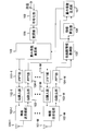
- FIG. 2 is a block diagram showing a functional configuration of the radio base station 100 in the present embodiment.
- the radio base station 100 in this embodiment includes an antenna 101-1 to 101-M, radio transceivers 102-1 to 102-M, and a guard interval (GI) guard removal unit 103.
- GI guard interval
- FFT fast Fourier transform
- a channel information acquisition unit 105 an index calculation unit 106
- a weight coefficient generation unit 107 a code Conversion section 108
- modulation section 109 modulation section
- weight coefficient multiplication section 110 inverse fast Fourier transform
- IFFT inverse fast Fourier transform
- Each of the antennas 101-1 to 101-M receives a radio frequency band signal transmitted by the radio terminal 200.
- Each of radio transmitting / receiving sections 102-1 to 102-M corresponds to each of antennas 101-1 to 101-M, and converts a received signal, which is a signal received by the corresponding antenna, into a baseband signal.
- Each of GI removal sections 103-1 to 103-M corresponds to each of radio transmission / reception sections 102-1 to 102-M, and from the received signal converted into a baseband signal by the corresponding radio transmission / reception section. Remove GI.
- Each of the FFT units 104-1 to 104-M corresponds to each of the GI removal units 103-1 to 103-M, and performs FFT on the reception signal from which the GI has been removed by the corresponding GI removal unit.
- the received signal is converted into a frequency domain signal.
- the propagation path information acquisition unit 105 uses the plurality of received signals converted into frequency domain signals by each of the FFT units 104-1 to 104-M, and is a radio that is a radio base station 100 and other radio communication devices.
- the propagation path information which is information related to the propagation path with the terminal 200, is acquired.
- the propagation path information is, for example, the frequency response of the propagation path between each of the antennas 101-1 to 101-M of the radio base station 100 and each of the antennas 201-1 to 201-N of the radio terminal 200.
- a method of acquiring propagation path information a first method in which the radio base station 100 estimates a propagation path state, and a second method in which the radio base station 100 receives a propagation path state estimated by the radio terminal 200, There is.
- An appropriate method is used in consideration of the amount of calculation required for acquiring the propagation path information and the accuracy of the propagation path information.
- the index calculation unit 106 uses the propagation path information acquired by the propagation path information acquisition unit 105 to calculate an index related to the angular spread of the propagation path. It is assumed that the index is a value that can be calculated with a smaller amount of calculation than the angular spread of the propagation path itself, not the angular spread of the propagation path itself. A more detailed description of the index will be described later.
- the weighting factor generation unit 107 uses the propagation path information acquired by the propagation path information acquisition unit 105 and the index calculated by the index calculation unit 106 to calculate a weighting coefficient corresponding to each of the antennas 101-1 to 101-M. Generate. A detailed description of the weighting coefficient generation method will be described later.
- the encoding unit 108 encodes transmission data addressed to the wireless terminal 200.
- the encoding method is not particularly limited.
- the modulation unit 109 modulates the transmission data encoded by the encoding unit 108.
- the modulation scheme is assumed to be a digital modulation scheme such as phase modulation (PSK: Phase Shift Keying) or quadrature amplitude modulation (QAM: Quadrature Amplitude Modulation).
- PSK Phase Shift Keying
- QAM Quadrature Amplitude Modulation
- Weight coefficient multiplication section 110 duplicates the modulation signal generated by modulation section 109 to generate a signal to be processed by each of antennas 101-1 to 101-M, and then generates a weight coefficient for each of the signals. Multiplying the weighting coefficient corresponding to each of the antennas 101-1 to 101-M generated by the unit 107 is performed.
- Each of IFFT sections 111-1 to 111 -M corresponds to each of antennas 101-1 to 101 -M, and among the transmission signals multiplied by the weighting coefficient by weighting coefficient multiplication section 110, the corresponding antenna is used. IFFT is performed on the transmission signal to be processed.
- Each of the GI insertion units 112-1 to 112-M corresponds to each of the IFFT units 111-1 to 111-M, and inserts a GI into the transmission signal subjected to IFFT in the corresponding IFFT unit.
- Radio transmission / reception units 102-1 to 102-M correspond to each of GI insertion units 112-1 to 112-M, and the transmission signal into which the GI has been inserted by the corresponding GI insertion unit is converted into a signal in the radio frequency band. Convert.
- Each of the antennas 101-1 to 101-M transmits a transmission signal converted into a signal of a radio frequency band by a radio transmission / reception unit corresponding to itself.
- FIG. 3 is a flowchart for explaining an example of a reception operation in the radio base station 100.
- each of the antennas 101-1 to 101-M of the radio base station 100 receives a radio frequency band signal transmitted from each of the antennas 201-1 to 201-N of the radio terminal 200, and receives the signal.
- the signal is output to the wireless transmission / reception unit corresponding to itself (step S301).
- Each of the radio transmission / reception units 102-1 to 102-M receives a reception signal from an antenna corresponding to itself, converts the reception signal into a baseband signal, and outputs the signal to a GI removal unit corresponding to itself ( Step S302).
- Each of the GI removal units 103-1 to 103-M receives a reception signal from the wireless transmission / reception unit corresponding to itself, removes the GI from the reception signal, and converts the reception signal from which the GI has been removed into an FFT corresponding to itself. (Step S303).
- Each of the FFT units 104-1 to 104-M receives a received signal from the GI removing unit corresponding to itself, performs FFT on the received signal, and transmits the received signal subjected to the FFT to the propagation path information acquiring unit 105. (Step S304).
- the propagation path information acquisition unit 105 receives a reception signal from each of the FFT units 104-1 to 104-M, and acquires propagation path information using the reception signal. Then, the propagation path information acquisition unit 105 outputs the acquired propagation path information to the index calculation unit 106 and the weight coefficient generation unit 107 (step S305).
- the index calculation unit 106 receives the propagation path information from the propagation path information acquisition unit 105, and calculates the index using the propagation path information. Then, the index calculation unit 106 outputs the calculated index to the weight coefficient generation unit 107 (step S306).
- the weight coefficient generation unit 107 receives propagation path information from the propagation path information acquisition unit 105 and receives an index from the index calculation unit 106. Then, weight coefficient generation section 107 generates a plurality of weight coefficients corresponding to each of antennas 101-1 to 101-M using the received propagation path information and index, and multiplies the plurality of weight coefficients by the weight coefficient.
- the data is output to the unit 110 (step S307), and the receiving operation is terminated.
- FIG. 4 is a flowchart for explaining an example of the transmission operation in the radio base station 100.
- the encoding unit 108 receives transmission data addressed to the radio terminal 200, encodes the transmission data, and outputs the encoded transmission data to the modulation unit 109 (step S401).
- Modulation section 109 receives transmission data from encoding section 108, modulates the transmission data, and outputs the modulated transmission data to weighting coefficient multiplication section 110 (step S402).
- the weighting factor multiplication unit 110 receives the modulation signal from the modulation unit 109 and receives the weighting factor output from the weighting factor generation unit 107 in step S307 of FIG.
- Weight coefficient multiplication section 110 duplicates the modulated signal to generate a transmission signal to be processed by each of antennas 101-1 to 101-M, and corresponds to the antenna that processes the transmission signal for each of the transmission signals. Multiply by the weighting factor. Then, the weighting factor multiplier 110 outputs each of the transmission signals multiplied by the weighting factor to the IFFT unit corresponding to the antenna that processes the transmission signal (step S403).
- Each of IFFT sections 111-1 to 111-M accepts a transmission signal from weight coefficient multiplication section 110, performs IFFT on the transmission signal, and transmits the transmission signal subjected to the IFFT to a GI insertion section corresponding to itself. (Step S404).
- Each of GI insertion sections 112-1 to 112-M receives a transmission signal from IFFT sections 111-1 to 111-M corresponding to itself, inserts a GI into the transmission signal, and transmits a transmission signal into which the GI is inserted. And output to the wireless transceiver corresponding to itself (step S405).
- Radio transmission / reception units 102-1 to 102-M receive transmission signals from GI insertion units 112-1 to 112-M corresponding to the radio transmission / reception units 102-1 to 102-M, convert the transmission signals into radio frequency band signals, and transmit the radio frequency band signals.
- the signal is output to the antenna corresponding to itself (step S406).
- Each of antennas 101-1 to 101-M receives a radio frequency band signal from radio transceivers 102-1 to 102-M corresponding to itself, transmits the signal (step S407), and ends the transmission process. .
- the index calculation unit 106 obtains a correlation between arbitrary antennas 101-1 to 101-M of the radio base station 100 using the propagation path information, and calculates an index based on the correlation. Specifically, assuming that the frequency response of the propagation path between the antenna 101-m of the radio base station 100 and the antenna 201-n of the radio terminal 200 is h n, m , the index calculation unit 106 represents the following equation (1) The index ⁇ is calculated from
- ⁇ m is a predetermined integer greater than or equal to 1 and less than M.
- the second term on the right side of Equation (1) corresponds to a correlation between antennas 10 m apart from antennas 101-1 to 101-M of radio base station 100.
- the index ⁇ calculated by the equation (1) is 0 or more and 1 or less.
- the index calculation unit 106 determines the frequency of the propagation path between the antennas 101-1 to 101-M of the radio base station 100 and the antennas 201-1 to 201-N of the radio terminal 200 based on the propagation path information.
- a matrix having a response as a component is constructed, an eigenvalue of a product of the matrix and the Hermitian transpose of the matrix is obtained, and an index is calculated based on the eigenvalue.
- an N ⁇ M ′ matrix whose n ⁇ m element has a frequency response h n, m is H
- the index calculation unit 106 has an eigenvalue ⁇ of the product of the matrix H and the Hermitian transpose of the matrix H.
- the index ⁇ is calculated from the following equation (2) using i (1 ⁇ i ⁇ N).
- the eigenvalues lambda i satisfies ⁇ 1 ⁇ ⁇ 2 ⁇ ... ⁇ ⁇ N.
- the index according to the equation (2) can be calculated only when N is 2 or more.
- M ′ corresponds to the number of antennas contributing to the formation of directivity, and is an integer of 2 or more and M or less. Further, the value of M ′ need not be limited to one, and the index calculation unit 106 may calculate a plurality of indices corresponding to each of the plurality of M ′.
- the elements of the matrix H are frequency responses corresponding to the antennas 101-1 to 101-M ′ of the radio base station 100 in the above example, but the frequency responses corresponding to M ′ antennas arranged in succession. If it is.
- the index calculated by Expression (2) is 0 or more and 1 or less.
- the index calculation unit 106 performs propagation between the antennas 101-1 to 101-M of the radio base station 100 for each of the antennas 201-1 to 201-N of the radio terminal 200 based on the propagation path information.
- a vector having the frequency response of the road as an element is obtained, and an index is calculated based on an angle formed between the vectors.
- the index calculation unit 106 calculates the index ⁇ from the following expression (3), where h n is an M′-dimensional vector whose mth element is the frequency response h n, m .
- Equation 3 the subscript n ′ is
- M ′ corresponds to the number of antennas contributing to the formation of directivity, and is an integer of 2 or more and M or less, like the index calculated from the equation (2). . Further, the value of M ′ need not be limited to one, and the index calculation unit 106 may calculate an index corresponding to each of the plurality of M ′.
- the elements of the vector h n are frequency responses corresponding to the antennas 101-1 to 101-M ′ of the radio base station 100 in the above example, but the frequencies corresponding to M ′ antennas arranged in succession. Any response is acceptable. Further, the index calculated by the expression (3) is 0 or more and less than 1.
- the index is calculated based on the propagation path information acquired at a certain time, that is, the instantaneous propagation path state.
- the propagation path state fluctuates drastically, it is considered more appropriate to generate the weighting factor from the temporally averaged index than the index based on the instantaneous propagation path state.
- the index calculation unit 106 displays the index at time i.
- the index described above can be calculated with subcarriers that can acquire the frequency response of the propagation path. For this reason, when an index related to the angular spread of the propagation path can be calculated for a plurality of subcarriers, the index calculation unit 106 calculates an average value or maximum value of the indexes for the plurality of subcarriers as an index. May be.
- FIG. 5 is a flowchart for explaining a specific example of the operation of the weighting factor generator 107.
- the weight coefficient generation unit 107 first determines the number M (0) of antennas having a weight coefficient of 0 using the index calculated by the index calculation unit 106 (step S501). At this time, the weight coefficient generation unit 107 increases the value of M (0) as the angular spread of the propagation path increases.
- the weight coefficient generation section 107 constructs a propagation path matrix so that elements of ( MM (0) ) antennas excluding the antenna whose weight coefficient is 0 are continuously arranged.
- the weighting factor generation unit 107 generates a weighting factor used when transmitting the signal addressed to the wireless terminal 200 using the propagation path matrix constructed in step S502 (step S503), and ends the process.
- the weight coefficient generation unit 107 determines the number M (0) of antennas having a weight coefficient of 0 using one index. Specifically, the index [rho, if the maximum value of M (0) was M (0) max, the weighting coefficient generation unit 107 determines M a (0) from the following equation (6). It is assumed that M (0) max is predetermined.
- the weight coefficient generation unit 107 determines the number M (0) of antennas having a weight coefficient of 0 using a plurality of indices.
- a plurality of indices means a plurality of indices calculated for each number of antennas that contribute to the formation of directivity using Expression (2) or (3).
- the index when the number of antennas contributing to the formation of directivity is (Mm (0) ) is
- the weight coefficient generation unit 107 sets the minimum m (0) that satisfies the following expression (7) when m (0) is changed from 0 to M ⁇ 2.
- the number of antennas M (0) with a weighting factor of 0 is determined.
- the weight coefficient generation unit 107 limits M (0) according to the propagation path information so that the received signal power at the radio terminal 200 does not become too small. For example, the weight coefficient generation unit 107 sets the maximum m (0) satisfying the following equation (8) when m (0) is changed from 0 to M ⁇ 2, and the number of antennas with the weight coefficient being 0. Determined as the upper limit of M (0) .
- Equation (8) h n, m is the frequency response of the propagation path between the antenna 101- m of the radio base station 100 and the antenna 201-n of the radio terminal 200, and ⁇ is a predetermined threshold value. It is.
- the antennas having a weighting factor of 0 are antennas 101- (MM (0) +1) to 101-M, and N ⁇ (N ⁇ ( MM (0) )
- the element of the n-th row and the m-th column of the matrix H is assumed to be h n, m .
- the weight coefficient generation unit 107 first performs singular value decomposition of the matrix H as in the following Expression (9).
- U is an N-dimensional unitary matrix having the left singular vector of the matrix H as a column vector
- ⁇ is N ⁇ (M ⁇ , whose diagonal element is a singular value and whose off-diagonal element is zero.
- M (0) matrix
- V is a (MM (0) ) dimensional unitary matrix having the right singular vector of matrix H as a column vector.
- the weight coefficient generation unit 107 uses the right singular vector v 1 corresponding to the maximum singular value for the M-dimensional weight coefficient vector w having the weight coefficient corresponding to each antenna as an element, and the following equation (10) Seek like.
- the right singular vector v 1 can also be derived from the eigenvalue decomposition of the product of the matrix H H and the matrix H.
- the weight coefficient generation unit 107 uses the vector h n ′ having the maximum norm in the vector h n (1 ⁇ n ⁇ N) to calculate the weight coefficient vector w using the following equation (12). )
- the weighting factor corresponding to each antenna 101-1 to 101-M of the radio base station 100 is based on the index related to the angular spread of the propagation path. Is generated. For this reason, the directivity can be formed by accurately estimating the fluctuation in the direction of good propagation path quality, and the amount of communication quality degradation with respect to the case where the ideal directivity is formed can be reduced.
- the index is calculated based on the correlation between the antennas 101-1 to 101-M of the radio base station 100, it is possible to accurately estimate the fluctuation in the direction of good propagation path quality. .
- the index is calculated based on the eigenvalue of the product of the matrix having the frequency response of the propagation path between the radio base station 100 and the radio terminal 200 as a component and the Hermitian transpose of the matrix, It is possible to accurately estimate fluctuations in the direction of good road quality.
- the frequency response of the propagation path between the antennas 101-1 to 101-M of the radio base station 100 constructed for each of the antennas 201-1 to 201-N of the radio terminal 200 is used as an element. Since the index is calculated based on the angle formed between the vectors to be performed, it is possible to accurately estimate the fluctuation in the direction of good propagation path quality.
- an index related to the angular spread of the propagation path averaged over time, or an index related to the angular spread of the propagation path averaged in frequency is calculated. Therefore, it is possible to estimate the fluctuation in the good direction of the propagation path quality with higher accuracy.
- the beam width of the directivity formed by the antennas 101-1 to 101-M of the radio base station 100 is adjusted based on the index, so that the ideal directivity is formed.
- the amount of communication quality degradation can be reduced.
- the number of weight coefficients corresponding to the index is set to 0, and the directivity beam width formed by the antennas 101-1 to 101-M of the radio base station 100 is adjusted.
- the beam width can be adjusted.
- the greater the angular spread of the propagation path the more the weighting factor is set to 0. Therefore, it is possible to adjust the beam width to be suitable for fluctuations in the direction of good propagation path quality.
- the upper limit of the number of weighting factors set to 0 is determined based on the propagation path information, it is possible to suppress the reception signal power at the radio terminal 200 from becoming too small.
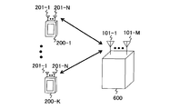
- FIG. 6 is a configuration diagram illustrating a wireless communication system according to the second embodiment of the present invention.
- the same components as those in FIG. 1 are denoted by the same reference numerals, and the description thereof is omitted.
- the radio communication system according to the present embodiment illustrated in FIG. 6 includes a radio base station 600 instead of the radio base station 100 as compared with the radio communication system according to the first embodiment illustrated in FIG. Is different in that there are multiple.
- FIG. 6 there are K wireless terminals 200, and the K wireless terminals 200 are referred to as wireless terminals 200-1 to 200-K, respectively.
- FIG. 7 is a block diagram showing a functional configuration of the radio base station 600 in the present embodiment.
- the same components as those in FIG. 2 are denoted by the same reference numerals, and the description thereof is omitted.
- the radio base station 600 illustrated in FIG. 7 includes a weight coefficient generation unit 601 instead of the weight coefficient generation unit 107, as compared with the radio base station 100 in the first embodiment illustrated in FIG. 602 is newly provided, a plurality of encoding units 108 and modulation units 109 are provided, and a weighting factor multiplication unit 603 is provided instead of the weighting factor multiplication unit 110.
- a weight coefficient generation unit 601 instead of the weight coefficient generation unit 107, as compared with the radio base station 100 in the first embodiment illustrated in FIG. 602 is newly provided, a plurality of encoding units 108 and modulation units 109 are provided, and a weighting factor multiplication unit 603 is provided instead of the weighting factor multiplication unit 110.
- Q encoding units 108 and modulation units 109 there are Q encoding units 108 and modulation units 109, and the Q encoding units 108 and modulation units 109 are respectively encoded units 108-1 to 108-Q and modulation units 109-1. ⁇ 109
- the weight coefficient generation unit 601 determines the number L of data blocks to be spatially multiplexed based on the index calculated by the index calculation unit 106. However, L is Q or less.
- the data block construction unit 602 constructs L data blocks determined by the weight coefficient generation unit 601 from a plurality of transmission data for the wireless terminals 200-1 to 200-K.
- Each of modulation units 109-1 to 109-Q corresponds to each of encoding units 108 to 108-Q, and L modulation units 109-1 to 109- of modulation units 109-1 to 109-Q are included. L modulates the data block encoded by the corresponding encoding unit.
- Weighting factor multiplication section 603 duplicates the modulation signal corresponding to each data block generated by modulation sections 109-1 to 109-L by the number M of antennas, and for the (L ⁇ M) modulation signals. The weight coefficient generated by the weight coefficient generation unit 107 is multiplied. Then, weight coefficient multiplication section 603 adds up the corresponding L modulated modulation signals for each of antennas 101-1 to 101-M.
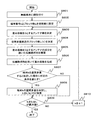
- FIG. 8 is a flowchart for explaining an example of the operation of the weighting factor generator 601.
- the weighting factor generation unit 601 uses the radio terminals 200-1 to 200-based on the propagation path information, the frequency at which radio resources are allocated to the radio terminals 200-1 to 200-K, and the like. Priorities are given to 200-K (step S801). Here, it is assumed that weighting factor generation section 601 assigns terminal numbers as priorities to each of wireless terminals 200-1 to 200-K in the order of preferential data transmission.
- the weight coefficient generation unit 601 sets the initial value 1 having the highest priority as the terminal number k, and sets the initial value 0 as the number L of data blocks to be spatially multiplexed (step S802).
- the weight coefficient generation unit 601 uses the index calculated by the index calculation unit 106 to transmit a signal addressed to the wireless terminal having the terminal number k, and the number of antennas M (0) with a weight coefficient of 0. (K) is determined (step S803).
- a method for determining M (0) (k) a method similar to the method for determining the number of antennas M (0) in which the weighting factor is 0 in the first embodiment can be used.
- the weighting factor generation unit 601 uses the propagation path information acquired by the propagation path information acquisition unit 105 and the number M (0) (k) of antennas having a weighting factor of 0 determined in step S803, The number L (k) of data blocks for transmitting a signal addressed to the wireless terminal with terminal number k is determined (step S804). For example, when the maximum value of the number of data blocks is L max , the weight coefficient generation unit 601 obtains L (k) from the following equation (13).
- the weight coefficient generation unit 601 limits the number of data blocks based on the channel quality. May be. Further, the maximum value L max of the number of data blocks is, for example, the number Q of the modulation unit 109 and the encoding unit 108.
- the weighting factor generation unit 601 constructs a propagation path matrix excluding the antenna component whose weighting factor is 0 (step S805).
- the weight coefficient generation unit 601 includes (MM (0) (k)) antenna elements continuously excluding the antenna whose weight coefficient is 0, and L (k) elements.
- a propagation path matrix is constructed so as not to overlap between data blocks.
- the weighting coefficient generation unit 601 uses the propagation path matrix constructed in step S805 to transmit an M-dimensional weighting coefficient vector w (k, j) (used when transmitting each data block to the wireless terminal having the terminal number k. 1 ⁇ j ⁇ L (k)) is generated (step S806).
- the weight coefficient generation unit 601 generates an M-dimensional weight coefficient vector w (k, j) using the right singular vector obtained from the singular value decomposition of the channel matrix.
- the weighting factor generation unit 601 uses the propagation path information and the weighting factor vector to determine whether or not a predetermined condition is satisfied when it is assumed that the signal addressed to the wireless terminal having the terminal number k is spatially multiplexed. Is determined (step S807).
- the predetermined condition is, for example, that the communication quality corresponding to each of the data block already determined to be spatially multiplexed and the data block addressed to the wireless terminal having the terminal number k exceeds a predetermined threshold value. is there.
- the terminal number of the wireless terminal corresponding to the data block that has already been determined to be spatially multiplexed and the terminal number k are collectively i
- the wireless terminal data block j ′ of the terminal number i ′ The communication quality is ⁇ (i ′, j ′), the threshold is ⁇ th, and the elements of n rows and m columns are between the antenna 101-m of the radio base station 600 and the antenna 201-n of the radio terminal 200-i ′.
- the predetermined condition can be expressed as the following equation (14).
- the weight coefficient generation unit 601 determines to perform spatial multiplexing transmission of the data block addressed to the wireless terminal having the terminal number k, and sets the number L of data blocks to L ( k) is added (step S808), and then it is determined whether the terminal number k or the number of data blocks L is the maximum value (step S809).
- step S807 when the predetermined condition is not satisfied (NO in step S807), the weight coefficient generation unit 601 performs step S809 without performing the process of step S808.
- step S809 If the terminal number k and the number of data blocks L are not the maximum values (NO in step S809), the weight coefficient generation unit 601 adds 1 to the terminal number (step S810), and returns to the process of step S803.
- the weight coefficient generation unit 601 ends the process.
- the antenna of the radio base station is composed of an antenna for vertical polarization and an antenna for horizontal polarization, and the angular spread of the propagation path for each polarization is increased.
- a weighting coefficient for generating a signal to be processed by each antenna is generated.
- the radio communication system and the radio base station in the present embodiment have the same configurations as the radio communication system and the radio base station 100 in the first embodiment shown in FIGS. 1 and 2, respectively.
- the antennas 101-1 to 101-M in the radio base station 100 are divided into vertical polarization antennas and horizontal polarization antennas.
- the index calculation unit 106 and the weight coefficient generation unit 107 Processing is performed in consideration of the angular spread of the propagation path for each of the horizontally polarized waves.
- the index calculation unit 106 uses the propagation path information acquired by the propagation path information acquisition unit 105 to calculate an index for each of the vertical polarization component and the horizontal polarization component. For the calculation of the index, any one of formulas (1), (2), and (3) may be used as in the first embodiment. At this time, the index calculation unit 106 uses the frequency response corresponding to the antenna for vertical polarization when calculating the index for the vertical polarization component, and calculates the horizontal response when calculating the index for the horizontal polarization component. The frequency response corresponding to the antenna for polarization is used.
- the weight coefficient generation unit 107 generates a weight coefficient based on the index for each polarization component. At this time, the weighting factor generation unit 107 may generate the weighting factor by performing an operation similar to the operation described with reference to FIG. 5, but the number of antennas having a weighting factor of 0 is determined for each polarization component. In the propagation path matrix, antenna elements whose weighting factors are not set to 0 are continuously arranged in each polarization antenna.
- signals processed by each antenna are used in consideration of the angular spread of the propagation path with respect to each direction using antennas arranged two-dimensionally in the horizontal direction and the vertical direction.
- a weighting factor for multiplying is generated.
- the radio communication system and the radio base station in the present embodiment have the same configurations as the radio communication system and the radio base station in the first embodiment shown in FIGS. 1 and 2, respectively.
- the antennas 101-1 to 101-M in the radio base station of the embodiment are two-dimensionally arranged, and the index calculation unit 106 and the weight coefficient generation unit 107 perform processing based on the indexes for the horizontal direction and the vertical direction, respectively. .
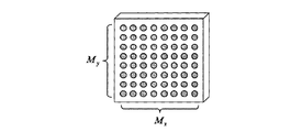
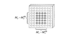
- FIG. 9 is a diagram showing the configuration of the antenna of this embodiment.
- the index calculation unit 106 calculates an index for each of the horizontal direction and the vertical direction based on the propagation path information.
- the index calculation unit 106 may use any one of the formulas (1), (2), and (3) shown in the first embodiment.
- the index calculation unit 106 calculates the index for the horizontal direction from the correlation between the antennas separated in the horizontal direction, and calculates the index for the vertical direction from the correlation between the antennas separated in the vertical direction. .
- the index calculation unit 106 calculates the index for the horizontal direction from the frequency response corresponding to the antenna that is continuous in the horizontal direction, and sets the index for the vertical direction in the vertical direction. Calculated from frequency response corresponding to continuous antennas.
- the weighting factor generation unit 107 generates a weighting factor using indices for each of the horizontal direction and the vertical direction. At this time, the weight coefficient generation unit 107 may generate the weight coefficient in the same manner as the operation of the first embodiment described with reference to FIG. 5, but the number of antennas having a weight coefficient of 0 is the horizontal direction and Antenna components that are determined for each of the vertical directions and whose weighting factor is not set to 0 in the propagation path matrix are arranged continuously in each of the horizontal and vertical directions as shown in FIG. However, in FIG. 10, M x (0) and M y (0) is the number of each antenna to 0 the weighting factor for the horizontal and vertical directions.
- Appendix 1 A wireless communication device having a plurality of antennas, A propagation path information acquisition unit for acquiring information about a propagation path between other wireless communication devices; Using the information, an index calculation unit that calculates an index related to the angular spread of the propagation path; A weighting factor generating unit that generates a weighting factor corresponding to each of the plurality of antennas using the information and the index; A wireless communication apparatus comprising: a weight coefficient multiplication unit that multiplies a signal processed by each of the plurality of antennas by the weight coefficient corresponding to the antenna that processes the signal.
- Appendix 2 The wireless communication apparatus according to appendix 1, wherein the index calculation unit obtains a correlation between arbitrary antennas of the plurality of antennas using the information, and calculates the index based on the correlation.
- the index calculation unit obtains an eigenvalue of a product of a matrix having a frequency response of the propagation path as an element and a Hermitian transpose of the matrix using the information, and calculates the index based on the eigenvalue.
- the wireless communication device according to 1.
- the index calculation unit obtains a vector having the frequency response of the propagation path as an element for each antenna included in the other wireless communication device using the information, and based on an angle formed between the vectors, the index
- the wireless communication apparatus according to appendix 1, wherein:
- the index calculation unit calculates, as the index, an index related to the angular spread of the propagation path averaged over time, or an index related to the angular spread of the propagation path averaged in frequency.
- the wireless communication device according to any one of appendices 1 to 4.
- Appendix 6 The radio according to any one of appendices 1 to 5, wherein the weighting factor generation unit generates the weighting factor so that a beam width of directivity formed by the plurality of antennas corresponds to the index. Communication device.
- the weighting factor generation unit sets the number of the weighting factors according to the index to 0, and uses the information to generate a weighting factor corresponding to an antenna whose weighting factor is not 0. Wireless communication device.
- Appendix 8 The wireless communication device according to appendix 7, wherein the weighting factor generation unit increases the number of the weighting factors set to 0 as the angular spread of the propagation path increases using the index.
- Appendix 9 The wireless communication device according to appendix 7 or 8, wherein the weighting factor generation unit determines an upper limit of the number of weighting factors to be set to 0 using the information.
- the weight coefficient generation unit determines the number of data blocks to be spatially multiplexed using the index, The wireless communication device according to any one of appendices 1 to 9, wherein the weighting factor multiplication unit processes a signal corresponding to the data block to be spatially multiplexed.
- Appendix 11 The wireless communication device according to appendix 10, wherein the weighting factor generation unit increases the number of the data blocks as the angular spread of the propagation path increases using the index.
- Appendix 12 The plurality of antennas include a vertically polarized antenna and a horizontally polarized antenna, The wireless communication apparatus according to any one of appendices 1 to 11, wherein the index calculation unit calculates the index corresponding to each of vertical polarization and horizontal polarization.
- Appendix 13 The plurality of antennas are two-dimensionally arranged in a first direction and a second direction, The wireless communication device according to any one of appendices 1 to 12, wherein the index calculation unit calculates the index corresponding to each of the first direction and the second direction.
- Appendix 14 A wireless communication method in a wireless communication device having a plurality of antennas, Get information about the propagation path between other wireless communication devices, Using the information, calculate an index related to the angular spread of the propagation path, Using the information and the indicator, generate a weighting factor corresponding to each of the plurality of antennas, A wireless communication method, wherein a signal processed by each of the plurality of antennas is multiplied by the weighting factor corresponding to the antenna processing the signal.
Landscapes
- Engineering & Computer Science (AREA)
- Signal Processing (AREA)
- Computer Networks & Wireless Communication (AREA)
- Radio Transmission System (AREA)
- Mobile Radio Communication Systems (AREA)
Abstract
Description
複数のアンテナを備えた無線通信装置であって、
他の無線通信装置との間の伝搬路に関する情報を取得する伝搬路情報取得部と、
前記情報を用いて、前記伝搬路の角度広がりに関連する指標を算出する指標算出部と、
前記情報および前記指標を用いて、前記複数のアンテナの各々に対応する重み係数を生成する重み係数生成部と、
前記複数のアンテナの各々で処理する信号に対して、当該信号を処理するアンテナに対応する前記重み係数を乗算する重み係数乗算部と、を有する。
複数のアンテナを備えた無線通信装置における無線通信方法であって、
他の無線通信装置との間の伝搬路に関する情報を取得し、
前記情報を用いて、前記伝搬路の角度広がりに関連する指標を算出し、
前記情報および前記指標を用いて、前記複数のアンテナの各々に対応する重み係数を生成し、
前記複数のアンテナの各々で処理する信号に対して、当該信号を処理するアンテナに対応する前記重み係数を乗算する。
(1.1)構成の説明
図1は、本発明の第1の実施形態における無線通信システムを示す構成図である。図1に示すように、本実施形態における無線通信システムは、無線基地局100と、無線端末200とを有する。
図3は、無線基地局100における受信動作の一例を説明するためのフローチャートである。
以下では、指標算出部106が算出する伝搬路の角度広がりに関連する指標の具体例を説明する。なお、以下の各例では、伝搬路の角度広がりが大きいほど、指標も大きくなる。






図5は、重み係数生成部107の動作の具体例を説明するためのフローチャートである。









以上説明したように本実施形態によれば、伝搬路の角度広がりに関連する指標に基づいて、無線基地局100の各アンテナ101-1~101-Mに対応する重み係数が生成される。このため、伝搬路品質の良好な方向の変動を精度良く見積もって指向性を形成でき、理想的な指向性を形成した場合に対する通信品質の劣化量を小さくできる。
本発明の第2実施形態では、複数のデータブロックを空間多重伝送する無線通信システムについて説明する。
図6は、本発明の第2の実施形態における無線通信システムを示す構成図である。なお、図6において、図1と同様の構成には同じ符号を付し、その説明を省略する。
図8は、重み係数生成部601の動作の一例を説明するためのフローチャートである。


重み係数生成部601は、処理を終了する。
以上説明したように、本実施形態によれば、指標に応じて複数のデータブロックが空間多重伝送されるので、第1の実施形態の効果に加えて、通信速度を向上することができる。
本発明の第3の実施形態では、無線基地局のアンテナが垂直偏波用のアンテナと水平偏波用のアンテナから構成され、各偏波に対する伝搬路の角度広がりを考慮して、各アンテナで処理する信号に乗算する重み係数を生成する。
本実施形態における無線通信システムおよび無線基地局は、それぞれ図1および図2に示した第1の実施形態における無線通信システムおよび無線基地局100と同様の構成を有するが、無線基地局100におけるアンテナ101-1~101-Mは、垂直偏波用のアンテナと水平偏波用のアンテナとに分かれており、指標算出部106および重み係数生成部107は、垂直偏波と水平偏波の各々に対する伝搬路の角度広がりを考慮して処理を行う。
以上説明したように、本実施形態によれば、垂直偏波と水平偏波の各々に対する指標が算出されるので、垂直偏波と水平偏波の各々に対する伝搬路の角度広がりを考慮して、各アンテナで処理する信号に乗算する重み係数を生成することができる。したがって、垂直偏波用と水平偏波用から構成されるアンテナを用いる環境において、理想的な指向性を形成した場合に対する通信品質の劣化量を小さくできる。
本発明の第4実施形態では、水平方向と垂直方向の2次元に配置したアンテナを用い、各方向に対する伝搬路の角度広がりを考慮して、各アンテナで処理する信号に乗算する重み係数を生成する。
本実施形態における無線通信システムおよび無線基地局は、それぞれ図1および図2に示した第1の実施形態における無線通信システムおよび無線基地局と同様の構成を有するが、本実施形態の無線基地局におけるアンテナ101-1~101-Mは、2次元に配置され、指標算出部106および重み係数生成部107は、水平方向および垂直方向の各々に対する指標に基づいて処理を行う。
以上説明したように、本実施形態によれば、水平方向と垂直方向の各々に対する指標が算出されるので、水平方向と垂直方向の各々に対する伝搬路の角度広がりを考慮して、各アンテナで処理する信号に乗算する重み係数を生成することができる。したがって、水平方向と垂直方向の2次元方向に配置されたアンテナを用いる環境において、理想的な指向性を形成した場合に対する通信品質の劣化量を小さくできる。
複数のアンテナを備えた無線通信装置であって、
他の無線通信装置との間の伝搬路に関する情報を取得する伝搬路情報取得部と、
前記情報を用いて、前記伝搬路の角度広がりに関連する指標を算出する指標算出部と、
前記情報および前記指標を用いて、前記複数のアンテナの各々に対応する重み係数を生成する重み係数生成部と、
前記複数のアンテナの各々で処理する信号に対して、当該信号を処理するアンテナに対応する前記重み係数を乗算する重み係数乗算部と、を有する無線通信装置。
前記指標算出部は、前記情報を用いて、前記複数のアンテナにおける任意のアンテナ間の相関を求め、当該相関に基づいて、前記指標を算出する、付記1に記載の無線通信装置。
前記指標算出部は、前記情報を用いて、前記伝搬路の周波数応答を要素とする行列と当該行列のエルミート転置との積の固有値を求め、当該固有値に基づいて、前記指標を算出する、付記1に記載の無線通信装置。
前記指標算出部は、前記情報を用いて、前記伝搬路の周波数応答を要素とするベクトルを前記他の無線通信装置が備えるアンテナごとに求め、前記ベクトルの間の成す角に基づいて、前記指標を算出する、付記1に記載の無線通信装置。
前記指標算出部は、前記指標として、時間的に平均化された前記伝搬路の角度広がりに関連する指標、または、周波数的に平均化された前記伝搬路の角度広がりに関連する指標を算出する、付記1ないし4のいずれか1項に記載の無線通信装置。
前記重み係数生成部は、前記複数のアンテナにより形成される指向性のビーム幅が、前記指標に対応するように、前記重み係数を生成する、付記1ないし5のいずれか1項に記載の無線通信装置。
前記重み係数生成部は、前記指標に応じた数の前記重み係数を0に設定し、前記情報を用いて、前記重み係数が0でないアンテナに対応する重み係数を生成する、付記6に記載の無線通信装置。
前記重み係数生成部は、前記指標を用いて、前記伝搬路の角度広がりが大きいほど、0に設定する前記重み係数の数を多くする、付記7に記載の無線通信装置。
前記重み係数生成部は、前記情報を用いて、0に設定する前記重み係数の数の上限を決定する、付記7または8に記載の無線通信装置。
前記重み係数生成部は、前記指標を用いて、空間多重伝送するデータブロックの数を決定し、
前記重み係数乗算部は、前記空間多重伝送するデータブロックに対応する信号を処理する、付記1ないし9のいずれか1項に記載の無線通信装置。
前記重み係数生成部は、前記指標を用いて、前記伝搬路の角度広がりが大きいほど、前記データブロックの数を多くする、付記10に記載の無線通信装置。
前記複数のアンテナは、垂直偏波用のアンテナと水平偏波用のアンテナとを含み、
前記指標算出部は、垂直偏波および水平偏波の各々に対応する前記指標を算出する、付記1ないし11のいずれか1項に記載の無線通信装置。
前記複数のアンテナは、第1の方向および第2の方向の2次元に配置され、
前記指標算出部は、前記第1の方向および第2の方向の各々に対応する前記指標を算出する、付記1ないし12のいずれか1項に記載の無線通信装置。
複数のアンテナを備えた無線通信装置における無線通信方法であって、
他の無線通信装置との間の伝搬路に関する情報を取得し、
前記情報を用いて、前記伝搬路の角度広がりに関連する指標を算出し、
前記情報および前記指標を用いて、前記複数のアンテナの各々に対応する重み係数を生成し、
前記複数のアンテナの各々で処理する信号に対して、当該信号を処理するアンテナに対応する前記重み係数を乗算する、無線通信方法。
101-1~101-M、201-1~201-N アンテナ
102-1~102-M 無線送受信部
103-1~103-M ガードインターバル除去部
104-1~104-M 高速フーリエ変換部
105 伝搬路情報取得部
106 指標算出部
107、601 重み係数生成部
108、108-1~108-Q 符号化部
109、109-1~109-Q 変調部
110、603 重み係数乗算部
111-1~111-M 逆高速フーリエ変換部
112-1~112-M ガードインターバル挿入部
200、200-1~200-K 無線端末
602 データブロック構築部
Claims (10)
- 複数のアンテナを備えた無線通信装置であって、
他の無線通信装置との間の伝搬路に関する情報を取得する伝搬路情報取得部と、
前記情報を用いて、前記伝搬路の角度広がりに関連する指標を算出する指標算出部と、
前記情報および前記指標を用いて、前記複数のアンテナの各々に対応する重み係数を生成する重み係数生成部と、
前記複数のアンテナの各々で処理する信号に対して、当該信号を処理するアンテナに対応する前記重み係数を乗算する重み係数乗算部と、を有する無線通信装置。 - 前記指標算出部は、前記情報を用いて、前記複数のアンテナにおける任意のアンテナ間の相関を求め、当該相関に基づいて、前記指標を算出する、請求項1に記載の無線通信装置。
- 前記指標算出部は、前記情報を用いて、前記伝搬路の周波数応答を要素とする行列と当該行列のエルミート転置との積の固有値を求め、当該固有値に基づいて、前記指標を算出する、請求項1に記載の無線通信装置。
- 前記指標算出部は、前記情報を用いて、前記伝搬路の周波数応答を要素とするベクトルを前記他の無線通信装置が備えるアンテナごとに求め、前記ベクトルの間の成す角に基づいて、前記指標を算出する、請求項1に記載の無線通信装置。
- 前記重み係数生成部は、前記複数のアンテナにより形成される指向性のビーム幅が、前記指標に対応するように、前記重み係数を生成する、請求項1ないし4のいずれか1項に記載の無線通信装置。
- 前記重み係数生成部は、前記指標に応じた数の前記重み係数を0に設定し、前記情報を用いて、前記重み係数が0でないアンテナに対応する重み係数を生成する、請求項5に記載の無線通信装置。
- 前記重み係数生成部は、前記指標を用いて、空間多重伝送するデータブロックの数を決定し、
前記重み係数乗算部は、前記空間多重伝送するデータブロックに対応する信号を処理する、請求項1ないし6のいずれか1項に記載の無線通信装置。 - 前記複数のアンテナは、垂直偏波用のアンテナと水平偏波用のアンテナとを含み、
前記指標算出部は、垂直偏波および水平偏波の各々に対応する前記指標を算出する、請求項1ないし7のいずれか1項に記載の無線通信装置。 - 前記複数のアンテナは、第1の方向および第2の方向の2次元に配置され、
前記指標算出部は、前記第1の方向および第2の方向の各々に対応する前記指標を算出する、請求項1ないし8のいずれか1項に記載の無線通信装置。 - 複数のアンテナを備えた無線通信装置における無線通信方法であって、
他の無線通信装置との間の伝搬路に関する情報を取得し、
前記情報を用いて、前記伝搬路の角度広がりに関連する指標を算出し、
前記情報および前記指標を用いて、前記複数のアンテナの各々に対応する重み係数を生成し、
前記複数のアンテナの各々で処理する信号に対して、当該信号を処理するアンテナに対応する前記重み係数を乗算する、無線通信方法。
Priority Applications (2)
| Application Number | Priority Date | Filing Date | Title |
|---|---|---|---|
| JP2015550580A JPWO2015079726A1 (ja) | 2013-11-29 | 2014-05-22 | 無線通信装置および無線通信方法 |
| US15/031,798 US20160248495A1 (en) | 2013-11-29 | 2014-05-22 | Radio Communication Apparatus and Radio Communication Method |
Applications Claiming Priority (2)
| Application Number | Priority Date | Filing Date | Title |
|---|---|---|---|
| JP2013247676 | 2013-11-29 | ||
| JP2013-247676 | 2013-11-29 |
Publications (1)
| Publication Number | Publication Date |
|---|---|
| WO2015079726A1 true WO2015079726A1 (ja) | 2015-06-04 |
Family
ID=53198684
Family Applications (1)
| Application Number | Title | Priority Date | Filing Date |
|---|---|---|---|
| PCT/JP2014/063569 Ceased WO2015079726A1 (ja) | 2013-11-29 | 2014-05-22 | 無線通信装置および無線通信方法 |
Country Status (3)
| Country | Link |
|---|---|
| US (1) | US20160248495A1 (ja) |
| JP (1) | JPWO2015079726A1 (ja) |
| WO (1) | WO2015079726A1 (ja) |
Cited By (1)
| Publication number | Priority date | Publication date | Assignee | Title |
|---|---|---|---|---|
| WO2023162184A1 (ja) * | 2022-02-25 | 2023-08-31 | 日本電信電話株式会社 | 無線通信方法、分散アンテナシステム及び無線通信装置 |
Families Citing this family (2)
| Publication number | Priority date | Publication date | Assignee | Title |
|---|---|---|---|---|
| WO2016108483A1 (ko) * | 2014-12-30 | 2016-07-07 | 엘지전자(주) | 무선 통신 시스템에서 채널 추정을 수행하기 위한 방법 및 이를 위한 장치 |
| JP7762357B2 (ja) * | 2021-09-03 | 2025-10-30 | 日本電気株式会社 | 無線受信装置及びその方法 |
Citations (4)
| Publication number | Priority date | Publication date | Assignee | Title |
|---|---|---|---|---|
| JP2002026806A (ja) * | 2000-05-24 | 2002-01-25 | Lucent Technol Inc | マクロセルにサービスする基地局、マクロセル内のマイクロセルにサービスする方法 |
| JP2002368663A (ja) * | 2001-06-05 | 2002-12-20 | Matsushita Electric Ind Co Ltd | 適応アンテナ装置 |
| JP2007274251A (ja) * | 2006-03-31 | 2007-10-18 | Kddi Corp | アレーアンテナ送信装置 |
| JP2008278076A (ja) * | 2007-04-26 | 2008-11-13 | Kyocera Corp | 無線通信装置 |
Family Cites Families (3)
| Publication number | Priority date | Publication date | Assignee | Title |
|---|---|---|---|---|
| JP3895228B2 (ja) * | 2002-05-07 | 2007-03-22 | 松下電器産業株式会社 | 無線通信装置および到来方向推定方法 |
| EP2169888A1 (en) * | 2008-09-30 | 2010-03-31 | NTT DoCoMo Inc. | A three dimensional pilot aided radio channel estimator |
| US8467363B2 (en) * | 2011-08-17 | 2013-06-18 | CBF Networks, Inc. | Intelligent backhaul radio and antenna system |
-
2014
- 2014-05-22 JP JP2015550580A patent/JPWO2015079726A1/ja active Pending
- 2014-05-22 US US15/031,798 patent/US20160248495A1/en not_active Abandoned
- 2014-05-22 WO PCT/JP2014/063569 patent/WO2015079726A1/ja not_active Ceased
Patent Citations (4)
| Publication number | Priority date | Publication date | Assignee | Title |
|---|---|---|---|---|
| JP2002026806A (ja) * | 2000-05-24 | 2002-01-25 | Lucent Technol Inc | マクロセルにサービスする基地局、マクロセル内のマイクロセルにサービスする方法 |
| JP2002368663A (ja) * | 2001-06-05 | 2002-12-20 | Matsushita Electric Ind Co Ltd | 適応アンテナ装置 |
| JP2007274251A (ja) * | 2006-03-31 | 2007-10-18 | Kddi Corp | アレーアンテナ送信装置 |
| JP2008278076A (ja) * | 2007-04-26 | 2008-11-13 | Kyocera Corp | 無線通信装置 |
Non-Patent Citations (1)
| Title |
|---|
| MANATO SHIMIZU ET AL.: "Performance Evaluation of Clustering Size Control Scheme Using Frequency Correlation in the Presence of Angular Spread for OFDM Adaptive Array Antenna", PROCEEDINGS OF THE SOCIETY CONFERENCE OF IEICE, 30 August 2011 (2011-08-30) * |
Cited By (2)
| Publication number | Priority date | Publication date | Assignee | Title |
|---|---|---|---|---|
| WO2023162184A1 (ja) * | 2022-02-25 | 2023-08-31 | 日本電信電話株式会社 | 無線通信方法、分散アンテナシステム及び無線通信装置 |
| JPWO2023162184A1 (ja) * | 2022-02-25 | 2023-08-31 |
Also Published As
| Publication number | Publication date |
|---|---|
| JPWO2015079726A1 (ja) | 2017-03-16 |
| US20160248495A1 (en) | 2016-08-25 |
Similar Documents
| Publication | Publication Date | Title |
|---|---|---|
| CN110518961B (zh) | 大规模mimo卫星移动通信方法及系统 | |
| EP2652885B1 (en) | Beamforming method, apparatus for polarized antenna array and radio communication device and system thereof | |
| US11228363B2 (en) | OAM multiplexing communication system and inter-mode interference elimination method | |
| JP5230766B2 (ja) | 到来方向推定装置及び到来方向推定方法 | |
| EP2515451B1 (en) | Data transmission method and system for cooperative multiple input multiple output beam-forming | |
| JP2011244475A (ja) | 無線通信装置及び無線通信方法 | |
| JP2004120536A (ja) | 適応アンテナ無線通信装置 | |
| US11616663B2 (en) | Method and apparatus of parameter tracking for CSI estimation | |
| JPWO2019172412A1 (ja) | 無線装置及びチャネル予測方法 | |
| CN117616702A (zh) | 稳健的端口选择 | |
| JP4459254B2 (ja) | 無線通信装置 | |
| EP3360265B1 (en) | Channel condition estimation | |
| WO2015079726A1 (ja) | 無線通信装置および無線通信方法 | |
| JP2010157805A (ja) | 送信装置および送受信方法 | |
| CN102082594B (zh) | 波束形成方法、装置和发射系统 | |
| JP4001880B2 (ja) | 空間多重伝送装置 | |
| JP4040588B2 (ja) | 空間多重伝送用送信装置 | |
| CN102315873B (zh) | 一种交叉极化天线系统接收合并方法及装置 | |
| JP5350128B2 (ja) | 空間分割多重装置および空間分割多元接続装置 | |
| JP5121754B2 (ja) | 無線通信方法、受信用基地局、及び中継局 | |
| JP2007036403A (ja) | 空間多重送信装置および送信方法 | |
| JP2008312228A (ja) | 適応アンテナ無線通信装置及び適応アンテナ無線通信方法 | |
| CN103179569A (zh) | 通信中数据中继的方法和中继设备 | |
| JP2010283757A (ja) | 無線送信装置、無線受信装置、無線通信システム、無線送信方法、無線受信方法および無線通信方法 |
Legal Events
| Date | Code | Title | Description |
|---|---|---|---|
| 121 | Ep: the epo has been informed by wipo that ep was designated in this application |
Ref document number: 14865092 Country of ref document: EP Kind code of ref document: A1 |
|
| WWE | Wipo information: entry into national phase |
Ref document number: 15031798 Country of ref document: US |
|
| ENP | Entry into the national phase |
Ref document number: 2015550580 Country of ref document: JP Kind code of ref document: A |
|
| NENP | Non-entry into the national phase |
Ref country code: DE |
|
| 122 | Ep: pct application non-entry in european phase |
Ref document number: 14865092 Country of ref document: EP Kind code of ref document: A1 |